EP4397887A1 - Drive device - Google Patents
Drive device Download PDFInfo
- Publication number
- EP4397887A1 EP4397887A1 EP22907328.3A EP22907328A EP4397887A1 EP 4397887 A1 EP4397887 A1 EP 4397887A1 EP 22907328 A EP22907328 A EP 22907328A EP 4397887 A1 EP4397887 A1 EP 4397887A1
- Authority
- EP
- European Patent Office
- Prior art keywords
- bearing
- groove
- case
- axial direction
- oil
- Prior art date
- Legal status (The legal status is an assumption and is not a legal conclusion. Google has not performed a legal analysis and makes no representation as to the accuracy of the status listed.)
- Withdrawn
Links
Images




Classifications
-
- F—MECHANICAL ENGINEERING; LIGHTING; HEATING; WEAPONS; BLASTING
- F16—ENGINEERING ELEMENTS AND UNITS; GENERAL MEASURES FOR PRODUCING AND MAINTAINING EFFECTIVE FUNCTIONING OF MACHINES OR INSTALLATIONS; THERMAL INSULATION IN GENERAL
- F16C—SHAFTS; FLEXIBLE SHAFTS; ELEMENTS OR CRANKSHAFT MECHANISMS; ROTARY BODIES OTHER THAN GEARING ELEMENTS; BEARINGS
- F16C33/00—Parts of bearings; Special methods for making bearings or parts thereof
- F16C33/30—Parts of ball or roller bearings
- F16C33/58—Raceways; Race rings
-
- F—MECHANICAL ENGINEERING; LIGHTING; HEATING; WEAPONS; BLASTING
- F16—ENGINEERING ELEMENTS AND UNITS; GENERAL MEASURES FOR PRODUCING AND MAINTAINING EFFECTIVE FUNCTIONING OF MACHINES OR INSTALLATIONS; THERMAL INSULATION IN GENERAL
- F16C—SHAFTS; FLEXIBLE SHAFTS; ELEMENTS OR CRANKSHAFT MECHANISMS; ROTARY BODIES OTHER THAN GEARING ELEMENTS; BEARINGS
- F16C33/00—Parts of bearings; Special methods for making bearings or parts thereof
- F16C33/30—Parts of ball or roller bearings
- F16C33/66—Special parts or details in view of lubrication
- F16C33/6637—Special parts or details in view of lubrication with liquid lubricant
- F16C33/6681—Details of distribution or circulation inside the bearing, e.g. grooves on the cage or passages in the rolling elements
-
- F—MECHANICAL ENGINEERING; LIGHTING; HEATING; WEAPONS; BLASTING
- F16—ENGINEERING ELEMENTS AND UNITS; GENERAL MEASURES FOR PRODUCING AND MAINTAINING EFFECTIVE FUNCTIONING OF MACHINES OR INSTALLATIONS; THERMAL INSULATION IN GENERAL
- F16C—SHAFTS; FLEXIBLE SHAFTS; ELEMENTS OR CRANKSHAFT MECHANISMS; ROTARY BODIES OTHER THAN GEARING ELEMENTS; BEARINGS
- F16C19/00—Bearings with rolling contact, for exclusively rotary movement
- F16C19/02—Bearings with rolling contact, for exclusively rotary movement with bearing balls essentially of the same size in one or more circular rows
- F16C19/04—Bearings with rolling contact, for exclusively rotary movement with bearing balls essentially of the same size in one or more circular rows for radial load mainly
- F16C19/06—Bearings with rolling contact, for exclusively rotary movement with bearing balls essentially of the same size in one or more circular rows for radial load mainly with a single row or balls
-
- F—MECHANICAL ENGINEERING; LIGHTING; HEATING; WEAPONS; BLASTING
- F16—ENGINEERING ELEMENTS AND UNITS; GENERAL MEASURES FOR PRODUCING AND MAINTAINING EFFECTIVE FUNCTIONING OF MACHINES OR INSTALLATIONS; THERMAL INSULATION IN GENERAL
- F16C—SHAFTS; FLEXIBLE SHAFTS; ELEMENTS OR CRANKSHAFT MECHANISMS; ROTARY BODIES OTHER THAN GEARING ELEMENTS; BEARINGS
- F16C33/00—Parts of bearings; Special methods for making bearings or parts thereof
- F16C33/30—Parts of ball or roller bearings
- F16C33/58—Raceways; Race rings
- F16C33/583—Details of specific parts of races
- F16C33/586—Details of specific parts of races outside the space between the races, e.g. end faces or bore of inner ring
-
- F—MECHANICAL ENGINEERING; LIGHTING; HEATING; WEAPONS; BLASTING
- F16—ENGINEERING ELEMENTS AND UNITS; GENERAL MEASURES FOR PRODUCING AND MAINTAINING EFFECTIVE FUNCTIONING OF MACHINES OR INSTALLATIONS; THERMAL INSULATION IN GENERAL
- F16C—SHAFTS; FLEXIBLE SHAFTS; ELEMENTS OR CRANKSHAFT MECHANISMS; ROTARY BODIES OTHER THAN GEARING ELEMENTS; BEARINGS
- F16C33/00—Parts of bearings; Special methods for making bearings or parts thereof
- F16C33/30—Parts of ball or roller bearings
- F16C33/66—Special parts or details in view of lubrication
-
- F—MECHANICAL ENGINEERING; LIGHTING; HEATING; WEAPONS; BLASTING
- F16—ENGINEERING ELEMENTS AND UNITS; GENERAL MEASURES FOR PRODUCING AND MAINTAINING EFFECTIVE FUNCTIONING OF MACHINES OR INSTALLATIONS; THERMAL INSULATION IN GENERAL
- F16C—SHAFTS; FLEXIBLE SHAFTS; ELEMENTS OR CRANKSHAFT MECHANISMS; ROTARY BODIES OTHER THAN GEARING ELEMENTS; BEARINGS
- F16C33/00—Parts of bearings; Special methods for making bearings or parts thereof
- F16C33/30—Parts of ball or roller bearings
- F16C33/66—Special parts or details in view of lubrication
- F16C33/6637—Special parts or details in view of lubrication with liquid lubricant
- F16C33/6659—Details of supply of the liquid to the bearing, e.g. passages or nozzles
-
- F—MECHANICAL ENGINEERING; LIGHTING; HEATING; WEAPONS; BLASTING
- F16—ENGINEERING ELEMENTS AND UNITS; GENERAL MEASURES FOR PRODUCING AND MAINTAINING EFFECTIVE FUNCTIONING OF MACHINES OR INSTALLATIONS; THERMAL INSULATION IN GENERAL
- F16C—SHAFTS; FLEXIBLE SHAFTS; ELEMENTS OR CRANKSHAFT MECHANISMS; ROTARY BODIES OTHER THAN GEARING ELEMENTS; BEARINGS
- F16C33/00—Parts of bearings; Special methods for making bearings or parts thereof
- F16C33/30—Parts of ball or roller bearings
- F16C33/66—Special parts or details in view of lubrication
- F16C33/6637—Special parts or details in view of lubrication with liquid lubricant
- F16C33/6659—Details of supply of the liquid to the bearing, e.g. passages or nozzles
- F16C33/6677—Details of supply of the liquid to the bearing, e.g. passages or nozzles from radial inside, e.g. via a passage through the shaft and/or inner ring
-
- F—MECHANICAL ENGINEERING; LIGHTING; HEATING; WEAPONS; BLASTING
- F16—ENGINEERING ELEMENTS AND UNITS; GENERAL MEASURES FOR PRODUCING AND MAINTAINING EFFECTIVE FUNCTIONING OF MACHINES OR INSTALLATIONS; THERMAL INSULATION IN GENERAL
- F16C—SHAFTS; FLEXIBLE SHAFTS; ELEMENTS OR CRANKSHAFT MECHANISMS; ROTARY BODIES OTHER THAN GEARING ELEMENTS; BEARINGS
- F16C35/00—Rigid support of bearing units; Housings, e.g. caps, covers
- F16C35/04—Rigid support of bearing units; Housings, e.g. caps, covers in the case of ball or roller bearings
- F16C35/06—Mounting or dismounting of ball or roller bearings; Fixing them onto shaft or in housing
- F16C35/067—Fixing them in a housing
-
- F—MECHANICAL ENGINEERING; LIGHTING; HEATING; WEAPONS; BLASTING
- F16—ENGINEERING ELEMENTS AND UNITS; GENERAL MEASURES FOR PRODUCING AND MAINTAINING EFFECTIVE FUNCTIONING OF MACHINES OR INSTALLATIONS; THERMAL INSULATION IN GENERAL
- F16H—GEARING
- F16H57/00—General details of gearing
- F16H57/04—Features relating to lubrication or cooling or heating
-
- F—MECHANICAL ENGINEERING; LIGHTING; HEATING; WEAPONS; BLASTING
- F16—ENGINEERING ELEMENTS AND UNITS; GENERAL MEASURES FOR PRODUCING AND MAINTAINING EFFECTIVE FUNCTIONING OF MACHINES OR INSTALLATIONS; THERMAL INSULATION IN GENERAL
- F16H—GEARING
- F16H57/00—General details of gearing
- F16H57/04—Features relating to lubrication or cooling or heating
- F16H57/0467—Elements of gearings to be lubricated, cooled or heated
- F16H57/0469—Bearings or seals
- F16H57/0471—Bearing
Definitions
- the present disclosure relates to a drive device.
- Patent Document 1 Japanese Unexamined Patent Application Publication No. 2019-129608 ( JP 2019-129608 A )
- One aspect provides a drive device including a stationary member, a bearing, and a rotary member drivingly connected to a driving source and supported by the stationary member via the bearing so as to be rotatable about an axis.
- the rotary member is press-fitted to the bearing and the bearing is fitted to the stationary member.
- One or more grooves through which oil passes are formed on a surface of the bearing that faces the stationary member in a radial direction or on a surface of the stationary member that faces the bearing in the radial direction.
- the groove extends in an axial direction and in a circumferential direction about the axis, and is open on at least one side out of both sides of the bearing in the axial direction.
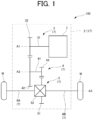
- FIG. 1 is a skeleton diagram of the vehicle drive system 100 including a rotary electric machine 1 and a power transmission mechanism 7.
- the input member 3 includes an input shaft 31 and an input gear 32.
- the input shaft 31 is a rotary member that rotates about a first axis A1.
- the input gear 32 is a gear that transmits a rotational torque (driving force) from the rotary electric machine 1 to the counter gear mechanism 4.
- the input gear 32 is provided to the input shaft 31 of the input member 3 so as to rotate integrally with the input shaft 31 of the input member 3.
- the second counter gear 43 is an output element of the counter gear mechanism 4.
- the second counter gear 43 has, for example, a smaller diameter than the first counter gear 42.
- the second counter gear 43 is provided to the counter shaft 41 so as to rotate integrally with the counter shaft 41.
- the rotary electric machine 1 thus drives the wheels W via the power transmission mechanism 7.
- other speed reducing mechanisms such as a planetary gear mechanism may be used.
- the case 2 and various components in the case 2 constitute the vehicle drive device 17 according to the present embodiment. Part or all of either or both of the left and right output members 6A, 6B need not essentially be housed in the case 2.
- the states of the groove 96 when the outer race 91 of the bearing 90 rotates relative to the case 2 are represented by reference numerals 96(1) to 96(4).
- the numerals 96(1) to 96(4) correspond to positions in chronological order.
- oil is transported from one side in the axial direction (Y2 side in FIG. 5 ) to the other side in the axial direction (Y1 side in FIG. 5 ) by the groove 96 (see arrow 300 in FIG. 5 ) as can be seen from changes in the groove 96 represented by 96(1) to 96(4).
- FIG. 10 is an explanatory diagram of preferred groove dispositions.
- FIG. 10 shows two variations (grooves 96A, 96B) as modifications of the groove 96. That is, the groove 96A is formed on the outer peripheral surface of an outer race 91A of a bearing 90A according to a first modification, and the groove 96B is formed on the outer peripheral surface of an outer race 91B of a bearing 90B according to a second modification.
- the configuration in which the grooves 96B are formed at a relatively high density as in the outer race 91B of the bearing 90B can be advantageous in that the suppliable amount of oil can be increased (and the coefficient of friction can be reduced accordingly).
- the contact area between the outer race 91B and the case 2 is reduced, which is disadvantageous in that the surface pressure increases.
- the groove on the outer peripheral surface of the outer race be formed, like the grooves 96A of the bearing 90A, so as to intersect a virtual line parallel to the axial direction on the outer peripheral surface of the outer race one time or less at each circumferential position.
- FIG. 10 shows a virtual line L800 at one circumferential position. In this case, the virtual line L800 intersects the groove 96A of the bearing 90A only once, but intersects the grooves 96B of the bearing 90B twice.
- intersection means cross-shaped intersection. Therefore, in a case of a virtual line L801 shown for the bearing 90A in FIG. 10 (virtual line L801 at another circumferential position), the virtual line L801 does not "intersect” the groove 96A though it is just in contact with the axial end (end on the Y1 side) of the groove 96A of the bearing 90A. In this respect, also in the case of the groove 96 according to the embodiment described above, the virtual line (not shown) in contact with one axial end of the groove 96 is in contact with the other axial end of the groove 96. Therefore, the number of times of intersection is one or less.
- the width of the groove 96D in a direction perpendicular to the longitudinal direction increases at both axial ends.
- a portion of the groove 96D on the near side is shown in black.
- the change from the width w0 to the width w1 in the groove 96D is realized in a gradual manner, but may be realized in a stepwise manner. That is, an angle ⁇ shown in FIG. 12 may be about 90 degrees.
- the corner related to the angle ⁇ shown in FIG. 12 may be rounded.
- the corner related to an angle ⁇ shown in FIG. 12 may be rounded.
Landscapes
- Engineering & Computer Science (AREA)
- General Engineering & Computer Science (AREA)
- Mechanical Engineering (AREA)
- Rolling Contact Bearings (AREA)
- General Details Of Gearings (AREA)
Abstract
Description
- The present disclosure relates to a drive device.
- There is known a lubrication circuit in which oil stored in a case is pumped up by an oil pump and the pumped oil is supplied to a power transmission mechanism to lubricate the power transmission mechanism (including bearings).
- Patent Document 1:
Japanese Unexamined Patent Application Publication No. 2019-129608 JP 2019-129608 A - However, the above related art does not have a mechanism for appropriately supplying oil from the oil pump to the surface of a bearing that faces the case in a radial direction and on which the bearing can slide relative to the case (e.g., in a case of clearance fit, a surface on a clearance fit side). Therefore, when creeping in which the bearing rotates relative to the case has occurred and the bearing comes into contact with the case, a relatively high radial load is applied to the case and the case may be worn.
- In one aspect, the present disclosure has an object to reduce the wear of a case due to creeping by providing a mechanism for appropriately supplying oil from an oil pump to the surface of a bearing.
- One aspect provides a drive device including a stationary member, a bearing, and a rotary member drivingly connected to a driving source and supported by the stationary member via the bearing so as to be rotatable about an axis. The rotary member is press-fitted to the bearing and the bearing is fitted to the stationary member. One or more grooves through which oil passes are formed on a surface of the bearing that faces the stationary member in a radial direction or on a surface of the stationary member that faces the bearing in the radial direction. The groove extends in an axial direction and in a circumferential direction about the axis, and is open on at least one side out of both sides of the bearing in the axial direction.
- In one aspect, according to the present disclosure, it is possible to reduce the wear of the case due to creeping by providing the mechanism for appropriately supplying oil from the oil pump to the surface of the bearing.
-
- [
FIG. 1] FIG. 1 is a skeleton diagram of a vehicle drive system including a rotary electric machine and a power transmission mechanism. - [
FIG. 2] FIG. 2 is an explanatory diagram of a bearing structure suitable for a vehicle drive device according to the present embodiment. - [
FIG. 3] FIG. 3 is an explanatory diagram of a groove formed on the outer peripheral surface of an outer race. - [
FIG. 4] FIG. 4 is an explanatory diagram of variations of a round shape of the bottom of the groove. - [
FIG. 5] FIG. 5 is an explanatory diagram of how oil is transported by the groove of the present embodiment. - [
FIG. 6] FIG. 6 is a diagram showing states when creeping in which a bearing rotates relative to a case has occurred. - [
FIG. 7] FIG. 7 is an explanatory diagram of a relationship between a torque generated in a direction in which the outer race rotates relative to the case and a torque generated in a direction in which the rotation of the outer race relative to the case is stopped. - [
FIG. 8] FIG. 8 is an explanatory diagram of variation characteristics of the torques according to a comparative example. - [
FIG. 9] FIG. 9 is an explanatory diagram of variation characteristics of the torques according to the present embodiment. - [
FIG. 10] FIG. 10 is an explanatory diagram of preferred groove dispositions according to a first modification and a second modification. - [
FIG. 11] FIG. 11 is an explanatory diagram of a groove formed on the outer peripheral surface of an outer race of a bearing according to a third modification. - [
FIG. 12] FIG. 12 is an enlarged view of a portion Q2 inFIG. 11 . - [
FIG. 13] FIG. 13 is a sectional view taken along line Q3-Q3 inFIG. 12 . - [
FIG. 14] FIG. 14 is a diagram corresponding toFIG. 12 in a case of a configuration without an oil reservoir. - [
FIG. 15] FIG. 15 is an explanatory diagram of a groove formed on the outer peripheral surface of an outer race of a bearing according to a fourth modification. - [
FIG. 16] FIG. 16 is an explanatory diagram of a groove formed on the outer peripheral surface of an outer race of a bearing according to a fifth modification. - [
FIG. 17] FIG. 17 is an explanatory diagram of a groove formed on the inner peripheral surface (surface that faces an outer race in a radial direction) of a case according to a sixth modification. - Embodiments will be described in detail below with reference to the accompanying drawings. The dimensional ratios in the drawings are merely illustrative, and are not limited to these. The shapes etc. in the drawings may be partially exaggerated for convenience of description.
- Hereinafter, a
vehicle drive system 100 to which avehicle drive device 17 according to the present embodiment is suitably applicable will be described first, and then a bearing structure of thevehicle drive device 17 according to the present embodiment will be described. -
FIG. 1 is a skeleton diagram of thevehicle drive system 100 including a rotaryelectric machine 1 and apower transmission mechanism 7. - In the example shown in
FIG. 1 , thevehicle drive system 100 includes the rotaryelectric machine 1 serving as a driving source of the vehicle and thepower transmission mechanism 7 provided in a power transmission path connecting the rotaryelectric machine 1 and wheels W. Thepower transmission mechanism 7 includes aninput member 3, acounter gear mechanism 4, adifferential gear mechanism 5, and left andright output members - The
input member 3 includes aninput shaft 31 and aninput gear 32. Theinput shaft 31 is a rotary member that rotates about a first axis A1. Theinput gear 32 is a gear that transmits a rotational torque (driving force) from the rotaryelectric machine 1 to thecounter gear mechanism 4. Theinput gear 32 is provided to theinput shaft 31 of theinput member 3 so as to rotate integrally with theinput shaft 31 of theinput member 3. - The
counter gear mechanism 4 is disposed between theinput member 3 and thedifferential gear mechanism 5 in the power transmission path. Thecounter gear mechanism 4 includes acounter shaft 41, afirst counter gear 42, and asecond counter gear 43. - The
counter shaft 41 is a rotary member that rotates about a second axis A2. The second axis A2 extends parallel to the first axis A1. Thefirst counter gear 42 is an input element of thecounter gear mechanism 4. Thefirst counter gear 42 meshes with theinput gear 32 of theinput member 3. Thefirst counter gear 42 is connected to thecounter shaft 41 so as to rotate integrally with thecounter shaft 41. - The
second counter gear 43 is an output element of thecounter gear mechanism 4. In the present embodiment, thesecond counter gear 43 has, for example, a smaller diameter than thefirst counter gear 42. Thesecond counter gear 43 is provided to thecounter shaft 41 so as to rotate integrally with thecounter shaft 41. - The
differential gear mechanism 5 is disposed on a third axis A3 serving as a rotation axis of thedifferential gear mechanism 5. The third axis A3 extends parallel to the first axis A1. Thedifferential gear mechanism 5 distributes the driving force transmitted from the rotaryelectric machine 1 side to the left andright output members differential gear mechanism 5 includes adifferential input gear 51, and thedifferential input gear 51 meshes with thesecond counter gear 43 of thecounter gear mechanism 4. Thedifferential gear mechanism 5 includes adifferential case 52, and thedifferential case 52 houses a pinion shaft, pinion gears, left and right side gears, etc. The left and right side gears are connected to the left andright output members right output members - The left and
right output members right output members differential gear mechanism 5 to the wheel W. The left andright output members - The rotary
electric machine 1 thus drives the wheels W via thepower transmission mechanism 7. In other embodiments, other speed reducing mechanisms such as a planetary gear mechanism may be used. - In the
vehicle drive system 100 shown inFIG. 1 , thecase 2 and various components in thecase 2 constitute thevehicle drive device 17 according to the present embodiment. Part or all of either or both of the left andright output members case 2. - The
vehicle drive device 17 according to the present embodiment is applicable not only to thevehicle drive system 100 having the specific configuration shown inFIG. 1 but also to various vehicle drive systems. Thevehicle drive device 17 is applicable to any vehicle drive system as long as it includes at least one rotary member drivingly connected to the wheels W so as to transmit power from the driving source (e.g., the rotaryelectric machine 1 or an engine) to the wheels W.. - Next, a characteristic configuration of the
vehicle drive device 17 according to the present embodiment will be described with reference toFIG. 2 and subsequent figures. -
FIG. 2 is an explanatory diagram of abearing structure 9 suitable for thevehicle drive device 17 according to the present embodiment, and is a schematic diagram viewed in an axial direction. InFIG. 2 , an X direction is defined as a direction perpendicular to the first axis A1, and an X1 side and an X2 side are defined along the X direction. The X direction may substantially correspond to, for example, the horizontal direction. - In the following, the bearing
structure 9 will be described taking an example in which it is applied to abearing 90 that rotatably supports theinput shaft 31 shown inFIG. 1 , but thebearing structure 9 may also be applied to other bearings (not shown) that rotatably support other rotary members in thevehicle drive device 17. - The
input shaft 31 that is a rotary member is press-fitted (tightly fitted) to thebearing 90, and thebearing 90 is fitted to thecase 2 that is a stationary member with a clearance. That is, in thebearing 90, anouter race 91 is fitted to a shaft hole of thecase 2 with a clearance, and theinput shaft 31 is press-fitted to a radially inner side of aninner race 92. In the example shown inFIG. 2 , thebearing 90 is a ball bearing, but may be another type of rolling bearing using rollers etc. Hereinafter, the surface of thebearing 90 that faces thecase 2 in the radial direction will also be referred to as "outer peripheral surface of theouter race 91". -
FIG. 3 is an explanatory diagram of agroove 96 formed on the outer peripheral surface of theouter race 91, and is a diagram showing thebearing 90 in a side view (viewed in the X direction from the X2 side) while part of thecase 2 inFIG. 2 (on the X2 side with respect to a line L200 inFIG. 2 ) and theinput shaft 31 are omitted.FIG. 3 schematically shows the other part of thecase 2 inFIG. 2 (on the X1 side with respect to the line L200 inFIG. 2 ). InFIG. 3 , a Y direction is defined as a direction parallel to the first axis A1, and a Y1 side and a Y2 side are defined along the Y direction. InFIG. 3 (the same applies toFIG. 5 etc. described later), oil is schematically shown as a hatchedarea 80.FIG. 4 is an explanatory diagram of variations of a round shape of the bottom of thegroove 96, and is a sectional view taken along line Q1-Q1 inFIG. 3 . - In the present embodiment, the
groove 96 through which oil passes is formed on the outer peripheral surface of theouter race 91 in the bearing 90 (surface that faces thecase 2 in the radial direction). Thegroove 96 may have a sectional shape with roundness at a bottom 960A, 960B, 960C as shown inFIG. 4. FIG. 4 schematically shows the sectional shape of thegroove 96.FIG. 4 schematically shows three types ofbottom groove 96. When the bottom 960A, 960B, 960C has such roundness, stress concentration at the bottom of thegroove 96 can be prevented, and thebearing 90 having thegroove 96 can be downsized. - The
groove 96 has a helical shape about an axis extending from one axial end of thebearing 90 to the other axial end, and is open in the axial direction at both the axial ends of thebearing 90. InFIG. 3 , thegroove 96 is schematically shown as a single line (dashed line on the X1 side at the back). -
FIG. 5 is an explanatory diagram of how oil is transported by thegroove 96 of the present embodiment, and is a diagram corresponding toFIG. 3 and illustrating a flow of oil along thegroove 96. - In
FIG. 5 , the states of thegroove 96 when theouter race 91 of thebearing 90 rotates relative to thecase 2 are represented by reference numerals 96(1) to 96(4). The numerals 96(1) to 96(4) correspond to positions in chronological order. When theouter race 91 of thebearing 90 rotates relative to thecase 2, oil is transported from one side in the axial direction (Y2 side inFIG. 5 ) to the other side in the axial direction (Y1 side inFIG. 5 ) by the groove 96 (seearrow 300 inFIG. 5 ) as can be seen from changes in thegroove 96 represented by 96(1) to 96(4). At this time, the helix direction of thegroove 96 is set such that oil in a space SP1 on one side of the bearing 90 in the axial direction (Y2 side inFIG. 5 ) is sent to the other side of the bearing 90 in the axial direction (Y1 side inFIG. 5 ) when theinput shaft 31 rotates in a rotation direction in conjunction with forward movement of the vehicle. With the axial oil flow through thegroove 96, the oil can appropriately be supplied between theouter race 91 of thebearing 90 and thecase 2 in the radial direction. Thus, the coefficient of friction between theouter race 91 of thebearing 90 and thecase 2 can be reduced effectively. Further effects related to this will be described later with reference toFIGS. 6 to 8 . - To secure an appropriate amount of oil to be supplied between the
outer race 91 of thebearing 90 and thecase 2 in the radial direction, it is preferable to provide anoil passage 36 through which oil is supplied to the space SP1 that is adjacent from one side in the axial direction (Y2 side inFIG. 5 ) with respect to thebearing 90. Thus, the oil supplied to the space SP1 can efficiently be supplied between theouter race 91 of thebearing 90 and thecase 2 in the radial direction. Part or all of theoil passage 36 may be formed in thecase 2 or may be formed in a tubular member separate from thecase 2. - According to the present embodiment, as described above, the oil can be transported from one side of the bearing 90 (Y2 side in
FIG. 5 ) to the other side (Y1 side inFIG. 5 ) by thegroove 96. Thus, it is possible to eliminate an oil passage with the same function. For example, in a configuration in which a rotor shaft (not shown) of the rotaryelectric machine 1 is made hollow to form an axial oil passage, oil from the axial oil passage can be supplied to thepower transmission mechanism 7 side (e.g., various lubrication target elements disposed in a space on thepower transmission mechanism 7 side in the case 2) via thebearing 90. - Next, the effects of the oil supplied as described above between the
outer race 91 of thebearing 90 and thecase 2 in the radial direction by thegroove 96 of the present embodiment will be described with reference toFIGS. 6 to 8 . - First, the main cause of wear of the
case 2 will be described with reference toFIG. 6. FIG. 6 is a diagram showing states S400 to S404 when creeping in which thebearing 90 rotates relative to thecase 2 has occurred. InFIG. 6 , arrows R91, R92 represent a rotation state and a rotation direction.FIG. 7 is an explanatory diagram of a relationship between a torque T1 generated in a direction in which theouter race 91 rotates relative to the case 2 (rotates clockwise in this case) and a torque T2 generated in a direction in which the rotation of theouter race 91 relative to the case 2 (clockwise rotation in this case) is stopped.FIG. 8 is a characteristic diagram according to a comparative example, andFIG. 9 is a characteristic diagram according to the present embodiment.FIGS. 8 and 9 show variation characteristics of the torques T1, T2 according to the comparative example and the present embodiment with the horizontal axis representing a rotation speed of theinner race 92 of thebearing 90 and the vertical axis representing a torque. The comparative example differs from the bearing 90 of the present embodiment in that thegroove 96 is not provided. - In state S400, the
outer race 91 of thebearing 90 is rotating relative to thecase 2, but the load is low and the rotation speed is high. Since the load applied between thecase 2 and theouter race 91 is low, no significant wear occurs. - In state S402 in which the load is high (see F4) and the rotation speed is low, the relatively high load (radial load F4) is generated due to solid contact of the
outer race 91 of the bearing 90 with the case 2 (see mark C400). Significant wear is likely to occur. When theouter race 91 of thebearing 90 comes into solid contact with thecase 2, the rotation of theouter race 91 relative to thecase 2 is stopped (see state S404), and then the state returns to state S400. When the transition from state S400 to state S404 is repeated, state S402 is repeated and the wear of thecase 2 is likely to progress. - State S402 and subsequent state S404 occur when the torque T1 (see
FIG. 7 ) is lower than the torque T2 (seeFIG. 7 ). That is, when torque T1 > torque T2, theouter race 91 continues to rotate (i.e., so-called co-rotation creeping occurs). If the coefficient of friction contributing to the torque T2 (coefficient of friction between thecase 2 and the outer race 91) can be reduced, the torque T2 can be reduced and the relationship of torque T1 > torque T2 can be achieved easily. - In this respect, unlike the bearing 90 of the present embodiment, as shown in
FIG. 8 , the relationship of torque T1 > torque T2 does not hold in a low rotation range (inFIG. 8 , a range equal to or lower than a rotation speed α) in the comparative example without thegroove 96. Therefore, state S402 and subsequent state S404 are likely to occur. Therefore, in the comparative example, state S402 is repeated and the wear of thecase 2 is likely to progress. - According to the present embodiment, as described above, the oil passing through the
groove 96 can reduce the coefficient of friction (coefficient of friction between thecase 2 and the outer race 91) contributing to the torque T2. Therefore, the relationship of torque T1 > torque T2 is easily maintained even in the low rotation range as shown inFIG. 9 . Thus, according to the present embodiment, the wear of thecase 2 can effectively be reduced by maintaining the relationship of torque T1 > torque T2 with the oil passing through thegroove 96. - Next, modifications of the
groove 96 will be described with reference toFIG. 10 and subsequent figures. -
FIG. 10 is an explanatory diagram of preferred groove dispositions.FIG. 10 shows two variations (grooves groove 96. That is, thegroove 96A is formed on the outer peripheral surface of anouter race 91A of abearing 90A according to a first modification, and thegroove 96B is formed on the outer peripheral surface of anouter race 91B of a bearing 90B according to a second modification. - Regarding both the
grooves groove 96 in the embodiment described above. Each of thegrooves groove 96 of the embodiment described above, but similarly has a helical shape. - Similarly to the
groove 96 according to the embodiment described above, the oil in the space SP1 can be sent to the other side of thebearings FIG. 10 ) through thegrooves input shaft 31 in the rotation direction in conjunction with forward movement of the vehicle. With the axial oil flow through thegrooves outer races bearings case 2 in the radial direction. Thus, the coefficient of friction between theouter races bearings case 2 can be reduced effectively. - The configuration in which the
grooves 96B are formed at a relatively high density as in theouter race 91B of the bearing 90B can be advantageous in that the suppliable amount of oil can be increased (and the coefficient of friction can be reduced accordingly). However, the contact area between theouter race 91B and thecase 2 is reduced, which is disadvantageous in that the surface pressure increases. - Therefore, it is preferable that the groove on the outer peripheral surface of the outer race be formed, like the
grooves 96A of the bearing 90A, so as to intersect a virtual line parallel to the axial direction on the outer peripheral surface of the outer race one time or less at each circumferential position.FIG. 10 shows a virtual line L800 at one circumferential position. In this case, the virtual line L800 intersects thegroove 96A of the bearing 90A only once, but intersects thegrooves 96B of the bearing 90B twice. - The term "intersect" means cross-shaped intersection. Therefore, in a case of a virtual line L801 shown for the
bearing 90A inFIG. 10 (virtual line L801 at another circumferential position), the virtual line L801 does not "intersect" thegroove 96A though it is just in contact with the axial end (end on the Y1 side) of thegroove 96A of thebearing 90A. In this respect, also in the case of thegroove 96 according to the embodiment described above, the virtual line (not shown) in contact with one axial end of thegroove 96 is in contact with the other axial end of thegroove 96. Therefore, the number of times of intersection is one or less. - By appropriately disposing the groove on the outer peripheral surface of the outer race in this way, it is possible to maximize the contact area between the outer race and the
case 2 while securing the necessary amount of oil supplied by the groove. By increasing the contact area between the outer race and thecase 2, the surface pressure can be reduced. Therefore, the outer race can be downsized (the radial thickness can be reduced). -
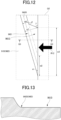
FIG. 11 is an explanatory diagram of agroove 96D formed on the outer peripheral surface of anouter race 91D of abearing 90D according to a third modification, and is a diagram in a side view similar to that ofFIG. 3 (viewed in the X direction from the X2 side).FIG. 12 is an enlarged view of a portion Q2 inFIG. 11 .FIG. 13 is a sectional view taken along line Q3-Q3 inFIG. 12 .FIG. 14 is a diagram corresponding toFIG. 12 in a case of a configuration without anoil reservoir 961D. - In the example shown in
FIGS. 11 to 13 , the width of thegroove 96D in a direction perpendicular to the longitudinal direction increases at both axial ends. InFIG. 11 , a portion of thegroove 96D on the near side is shown in black. - Specifically, as schematically shown in
FIG. 12 , the width of thegroove 96D in the direction perpendicular to the longitudinal direction is a width w0 in a normal section, and is a significantly larger width w1 than the width w0 at the end. As a result, thegroove 96D has an opening width w3 (= w1 / sinα) that is significantly larger than an opening width w2 (= w0 / sinα) in a case where thegroove 96D is open with the width w0. - According to the example shown in
FIGS. 11 to 13 , thegroove 96D has the relatively large opening width w3. Therefore, theoil reservoir 961D having a relatively large capacity can be formed at the end. Thus, the oil can efficiently be supplied into thegroove 96D (see arrow R12 inFIG. 12 ), and the oil transport function of thegroove 96D can be enhanced efficiently. - According to the example shown in
FIGS. 11 to 13 , the portion of the end of theouter race 91D that is adjacent to thegroove 96D can function as theoil reservoir 961D. Therefore, it is possible to reduce wear on thecase 2 side that may occur when theoil reservoir 961D is not provided. - Specifically, as shown in
FIG. 14 , when theoil reservoir 961D is not provided, aportion 912 of the axial end of theouter race 91D that is adjacent to thegroove 96 is tapered at the circumferential end. Therefore, a relatively high surface pressure may be applied to thecase 2 in contact with theportion 912. Such a relatively high surface pressure may accelerate the wear of thecase 2. - In this respect, according to the present embodiment, the
oil reservoir 961D that is not in contact with thecase 2 is formed in place of theportion 912 as described above. For example, theoil reservoir 961D may be formed by cutting theportion 912. Thus, it is possible to prevent a relatively high surface pressure from being applied to thecase 2. As a result, the wear on thecase 2 side caused by the axial end of theouter race 91D can be reduced effectively. - In the example shown in
FIGS. 11 to 13 , a bottom 960D of thegroove 96D is the bottom 960A described above with reference toFIG. 4 except for the section where theoil reservoir 961D is formed, but may be the bottom 960B, 960C. - In the example shown in
FIGS. 11 to 13 , theoil reservoirs 961D are formed at both axial ends of onegroove 96D, but theoil reservoir 961D may be formed only at one end (e.g., the end on the Y2 side). - In the example shown in
FIGS. 11 to 13 , the change from the width w0 to the width w1 in thegroove 96D is realized in a gradual manner, but may be realized in a stepwise manner. That is, an angle β shown inFIG. 12 may be about 90 degrees. The corner related to the angle β shown inFIG. 12 may be rounded. Similarly, the corner related to an angle γ shown inFIG. 12 may be rounded. - In the example shown in
FIGS. 11 to 13 , onegroove 96D is formed, but a plurality ofsimilar grooves 96D may be formed as described above with reference toFIG. 10 . Even in the case where the plurality ofsimilar grooves 96D is formed, an oil reservoir like theoil reservoir 961D described above with reference toFIGS. 11 to 13 may be formed. In the case where the plurality ofgrooves 96D is formed, the oil reservoir may be formed for each of the plurality ofgrooves 96D or may be formed in common for part or all of two or more of the plurality ofgrooves 96D. -
FIG. 15 is an explanatory diagram of agroove 96E formed on the outer peripheral surface of anouter race 91E of abearing 90E according to a fourth modification, and is a diagram in a side view similar to that ofFIG. 3 (viewed in the X direction from the X2 side). - The
groove 96E according to the present modification differs from thegroove 96 according to the embodiment described above in that it is open only on one axial end side (Y2 side). Specifically, thegroove 96E extends in the axial direction and in the circumferential direction about the axis, but returns to the Y2 side without being open in the axial direction at the end face of theouter race 91E on the Y1 side, and is open in the axial direction at the end face of theouter race 91E on the Y2 side. - Even in such a modification, the wear of the
case 2 can effectively be reduced as in the embodiment described above though the oil cannot efficiently be transported to the Y1 side via thegroove 96E. Thegroove 96E according to the present modification extends from the opening (inlet) on the Y2 side to the Y1 side and then returns to the Y2 side to open, thereby forming a loop once. However, thegroove 96E may extend to form loops twice or more. A plurality ofgrooves 96E may be formed in such a manner that a plurality of sets of inlets and outlets is formed on the Y2 side. In the present modification as well, an oil reservoir like theoil reservoir 961D described above with reference toFIGS. 11 to 13 may be formed. In the case where the plurality ofgrooves 96E is formed, the oil reservoir may be formed for each of the plurality ofgrooves 96E or may be formed in common for part or all of two or more of the plurality ofgrooves 96E. -
FIG. 16 is an explanatory diagram of agroove 96F formed on the outer peripheral surface of anouter race 91F of abearing 90F according to a fifth modification, and is a diagram in a side view similar to that ofFIG. 3 (viewed in the X direction from the X2 side). - The
outer race 91F according to the present modification differs from theouter race 91 according to the embodiment described above in that thegroove 96F is added. - Oil can be transported through the
groove 96F in a direction opposite to that of thegroove 96. Specifically, the oil can be sent from the Y1 side to the Y2 side through thegroove 96F when theinput shaft 31 rotates in the rotation direction in conjunction with forward movement of the vehicle. - Even with such a modification, the same effects as in the embodiment described above can be obtained. A plurality of
grooves 96F according to the present modification may be formed as described above with reference toFIG. 10 . In the present modification as well, an oil reservoir like theoil reservoir 961D described above with reference toFIGS. 11 to 13 may be formed. In the case where the plurality ofgrooves 96F is formed, the oil reservoir may be formed for each of the plurality ofgrooves 96F or may be formed in common for part or all of two or more of the plurality ofgrooves 96F. -
FIG. 17 is an explanatory diagram of agroove 96G formed on the inner peripheral surface (surface that faces theouter race 91 in the radial direction) of acase 2G according to a sixth modification, and is a schematic plan view of the developed inner peripheral surface of thecase 2G. An L direction shown inFIG. 17 corresponds to the circumferential direction. AlthoughFIG. 17 shows explanatory dashed lines representing the connection of thegroove 96G, the dashed lines are not lines representing thegroove 96G itself. A range SC1 shown inFIG. 17 schematically shows an axial range in which thebearing 90 extends. - In the present modification, the
groove 96G has a shape of a single helix and is formed in the axial range in which thebearing 90 extends (see the range SC1). That is, thehelical groove 96G faces theouter race 91 of thebearing 90 over the entire axial length of theouter race 91. InFIG. 17 , thegroove 96G extends beyond the bearing 90 on both axial sides of thebearing 90, and is therefore open on both the axial sides of thebearing 90. Also in the present modification, when thebearing 90 rotates along with the rotation of theinput shaft 31 as described above with reference toFIG. 6 (see S400), theouter race 91 rotates relative to thecase 2G. At this time, the oil in thegroove 96G flows in the axial direction along thehelical groove 96G by the friction between theouter race 91 and the oil in thegroove 96G. Such an axial oil flow is also facilitated by a relatively high oil viscosity. - Even with the present modification, the same effects as in the embodiment described above are obtained. That is, as described above, the oil passing through the
groove 96G can reduce the coefficient of friction (coefficient of friction between thecase 2G and the outer race 91). Therefore, the relationship of torque T1 > torque T2 is easily maintained even in the low rotation range as described above with reference toFIG. 9 . Thus, according to the present modification as well, the wear of thecase 2G can effectively be reduced by maintaining the relationship of torque T1 > torque T2 with the oil passing through thegroove 96G. - Also in the present modification, the helix direction of the
groove 96G may be set such that the oil in the space SP1 (seeFIG. 3 ) is sent to the Y1 side when theinput shaft 31 rotates in the rotation direction in conjunction with forward movement of the vehicle. With the axial oil flow through thegroove 96G, the coefficient of friction between theouter race 91 of thebearing 90 and thecase 2G can be reduced effectively. - Although the present modification relates to the
case 2G that may be used together with thebearing 90 having thegroove 96 described above, thecase 2G can also be suitably combined with a bearing without thegroove 96 described above. That is, in the present modification, thegroove 96 in thebearing 90 may be omitted. - In the present modification, the
groove 96G extends beyond the bearing 90 on both the axial sides of thebearing 90 to open on both the axial sides of thebearing 90, but thegroove 96G is not limited thereto. That is, thegroove 96G may be formed to open only on the Y2 side in the same concept as that of thegroove 96E described above with reference toFIG. 15 . - Although the embodiments are described in detail above, the present disclosure is not limited to the specific embodiments, and various modifications and changes can be made within the scope of the claims. It is also possible to combine all or some of the constituent elements according to the embodiments described above.
- For example, in the embodiment described above (and the other modifications as well; the same applies hereinafter), the
outer race 91 is fitted to thecase 2 with a clearance, but the present disclosure is not limited to this. That is, theouter race 91 is fitted to the stationary member with a clearance in the embodiment described above, but theinner race 92 may be fitted to the stationary member with a clearance. In this case, a groove similar to thegroove 96 described above may be formed on the inner peripheral surface of the inner race 92 (surface that faces the stationary member in the radial direction). - In the embodiment described above, the
outer race 91 is fitted to thecase 2 with a clearance, but the present disclosure is not limited to this. For example, theouter race 91 may be fitted to thecase 2 by transition fit or interference fit. In this case as well, the wear of thecase 2 can be reduced by forming thesimilar groove 96 in theouter race 91. - Although the embodiment described above is applied to the vehicle drive device that drives the wheels, it can also be applied to a vehicle drive device that transmits a driving force to an on-vehicle component other than wheels, or a drive device for purposes other than a vehicle. For example, the embodiment described above may be applied to a bearing structure related to a rotary member that is drivingly connected to an actuator in a variable valve timing mechanism or an electric oil pump. As described above, the embodiment described above is applicable to any power transmission mechanism, and may be applied to an AMT (Automated Manual Transmission).
- 17 ... vehicle drive device (drive device), 2 ... case (stationary member), 90, 90A-90F ... bearing, 31 ... input shaft (rotary member), 96, 96A-96G ... groove, 960A, 960B, 960C, 960D ... bottom, 36 ... oil passage, SP1 ... space, L800, L801 ... virtual line, W ... wheel
Claims (6)
- A drive device comprising:a stationary member;a bearing; anda rotary member drivingly connected to a driving source and supported by the stationary member via the bearing so as to be rotatable about an axis, whereinthe rotary member is press-fitted to the bearing and the bearing is fitted to the stationary member,one or more grooves through which oil passes are formed on a surface of the bearing that faces the stationary member in a radial direction or on a surface of the stationary member that faces the bearing in the radial direction, andthe groove extends in an axial direction and in a circumferential direction about the axis, and is open on at least one side out of both sides of the bearing in the axial direction.
- The drive device according to claim 1, wherein:the rotary member is drivingly connected to a wheel so as to transmit power from the driving source to the wheel;the drive device further includes an oil passage through which oil is supplied to a space that is adjacent from the one side of the bearing in the axial direction;the groove is open on the one side of the bearing in the axial direction so as to communicate with the space, and is open on the other side of the bearing in the axial direction; andthe groove is formed so as to send the oil supplied to the space from the one side of the bearing to the other side of the bearing in the axial direction when the rotary member rotates in a rotation direction in conjunction with forward movement of a vehicle.
- The drive device according to claim 1 or 2, wherein the groove has a sectional shape with a rounded bottom.
- The drive device according to any one of claims 1 to 3, wherein the groove is formed so as to intersect a virtual line parallel to the axial direction on the surface one time or less at each circumferential position about the axis.
- The drive device according to any one of claims 1 to 4, wherein the groove is formed in the bearing, has a helical shape about an axis extending from one end of the bearing in the axial direction to the other end of the bearing in the axial direction, and is open in the axial direction on both end faces of the bearing in the axial direction.
- The drive device according to any one of claims 1 to 5, wherein the groove is formed in the bearing, and a groove width in a direction perpendicular to a longitudinal direction increases at an end on the at least one side out of the both sides of the bearing in the axial direction.
Applications Claiming Priority (2)
| Application Number | Priority Date | Filing Date | Title |
|---|---|---|---|
| JP2021203764 | 2021-12-15 | ||
| PCT/JP2022/045184 WO2023112801A1 (en) | 2021-12-15 | 2022-12-07 | Drive device |
Publications (1)
| Publication Number | Publication Date |
|---|---|
| EP4397887A1 true EP4397887A1 (en) | 2024-07-10 |
Family
ID=86774627
Family Applications (1)
| Application Number | Title | Priority Date | Filing Date |
|---|---|---|---|
| EP22907328.3A Withdrawn EP4397887A1 (en) | 2021-12-15 | 2022-12-07 | Drive device |
Country Status (5)
| Country | Link |
|---|---|
| US (1) | US20240418218A1 (en) |
| EP (1) | EP4397887A1 (en) |
| JP (1) | JPWO2023112801A1 (en) |
| CN (1) | CN118302618A (en) |
| WO (1) | WO2023112801A1 (en) |
Family Cites Families (5)
| Publication number | Priority date | Publication date | Assignee | Title |
|---|---|---|---|---|
| JPH06133488A (en) * | 1992-10-13 | 1994-05-13 | Mitsubishi Electric Corp | Bearing device of rotating machine |
| JP2017053420A (en) * | 2015-09-09 | 2017-03-16 | 株式会社ジェイテクト | Rolling bearing |
| JP2019129608A (en) | 2018-01-24 | 2019-08-01 | トヨタ自動車株式会社 | Vehicle drive |
| US10612595B2 (en) * | 2018-08-13 | 2020-04-07 | Schaeffler Technologies AG & Co. KG | Lubrication groove for deep groove ball bearing |
| JP2020034076A (en) * | 2018-08-29 | 2020-03-05 | トヨタ自動車株式会社 | Power transmission device for vehicle |
-
2022
- 2022-12-07 EP EP22907328.3A patent/EP4397887A1/en not_active Withdrawn
- 2022-12-07 WO PCT/JP2022/045184 patent/WO2023112801A1/en not_active Ceased
- 2022-12-07 US US18/700,537 patent/US20240418218A1/en not_active Abandoned
- 2022-12-07 JP JP2023567728A patent/JPWO2023112801A1/ja active Pending
- 2022-12-07 CN CN202280077860.8A patent/CN118302618A/en active Pending
Also Published As
| Publication number | Publication date |
|---|---|
| WO2023112801A1 (en) | 2023-06-22 |
| CN118302618A (en) | 2024-07-05 |
| US20240418218A1 (en) | 2024-12-19 |
| JPWO2023112801A1 (en) | 2023-06-22 |
Similar Documents
| Publication | Publication Date | Title |
|---|---|---|
| US6406399B1 (en) | Planetary traction drive transmission | |
| US8323140B2 (en) | Reduction gear transmission | |
| US8939044B2 (en) | Retainer made of synthetic resin for use in a deep groove ball bearing; deep groove ball bearing; and gear support device | |
| US20120223606A1 (en) | Eccentric Magnetic Gear System Based on Repulsion | |
| US8739931B2 (en) | Lubricating structure of differential gear unit | |
| CN101260929B (en) | Vehicle planetary gear device | |
| US12546362B2 (en) | Transmission | |
| CN102639885A (en) | Spacer for radial needle bearing | |
| US20160160983A1 (en) | Differential device | |
| CN112762145B (en) | Eccentric swing type reduction gear | |
| US8545358B2 (en) | Gear transmission | |
| US10359099B1 (en) | Cycloidal differential | |
| US20190383372A1 (en) | Power take-off drive gear thrust load canceling | |
| JPH07317885A (en) | Rotational support device for planetary gears | |
| US20240418218A1 (en) | Drive device | |
| US6520041B2 (en) | Three parallel shaft type automatic transmission | |
| US6929578B1 (en) | Planetary gear carrier assembly | |
| JP4828847B2 (en) | Differential equipment | |
| EP1522768A2 (en) | Differential gearing for vehicle | |
| JPH07208586A (en) | Lubrication device for automatic transmission for vehicles | |
| US12044304B2 (en) | Differential with lubrication ports | |
| JP2007064365A (en) | Simple planetary gear mechanism planetary gear device and its series | |
| KR102159796B1 (en) | Driving apparatus for electric vehicle | |
| CN120175807A (en) | Reduction mechanism and vehicle | |
| SOE et al. | Design and strength analysis of the reverse-speed spur gear in the gearbox for the Toyota light truck |
Legal Events
| Date | Code | Title | Description |
|---|---|---|---|
| STAA | Information on the status of an ep patent application or granted ep patent |
Free format text: STATUS: THE INTERNATIONAL PUBLICATION HAS BEEN MADE |
|
| PUAI | Public reference made under article 153(3) epc to a published international application that has entered the european phase |
Free format text: ORIGINAL CODE: 0009012 |
|
| STAA | Information on the status of an ep patent application or granted ep patent |
Free format text: STATUS: REQUEST FOR EXAMINATION WAS MADE |
|
| 17P | Request for examination filed |
Effective date: 20240405 |
|
| AK | Designated contracting states |
Kind code of ref document: A1 Designated state(s): AL AT BE BG CH CY CZ DE DK EE ES FI FR GB GR HR HU IE IS IT LI LT LU LV MC ME MK MT NL NO PL PT RO RS SE SI SK SM TR |
|
| STAA | Information on the status of an ep patent application or granted ep patent |
Free format text: STATUS: THE APPLICATION HAS BEEN WITHDRAWN |
|
| 18W | Application withdrawn |
Effective date: 20241009 |