EP4397881A1 - Brake dust collector - Google Patents
Brake dust collector Download PDFInfo
- Publication number
- EP4397881A1 EP4397881A1 EP23197035.1A EP23197035A EP4397881A1 EP 4397881 A1 EP4397881 A1 EP 4397881A1 EP 23197035 A EP23197035 A EP 23197035A EP 4397881 A1 EP4397881 A1 EP 4397881A1
- Authority
- EP
- European Patent Office
- Prior art keywords
- main
- sub
- dust collector
- fastening
- housing
- Prior art date
- Legal status (The legal status is an assumption and is not a legal conclusion. Google has not performed a legal analysis and makes no representation as to the accuracy of the status listed.)
- Granted
Links
Images




Classifications
-
- F—MECHANICAL ENGINEERING; LIGHTING; HEATING; WEAPONS; BLASTING
- F16—ENGINEERING ELEMENTS AND UNITS; GENERAL MEASURES FOR PRODUCING AND MAINTAINING EFFECTIVE FUNCTIONING OF MACHINES OR INSTALLATIONS; THERMAL INSULATION IN GENERAL
- F16D—COUPLINGS FOR TRANSMITTING ROTATION; CLUTCHES; BRAKES
- F16D65/00—Parts or details
- F16D65/0031—Devices for retaining friction material debris, e.g. dust collectors or filters
-
- B—PERFORMING OPERATIONS; TRANSPORTING
- B01—PHYSICAL OR CHEMICAL PROCESSES OR APPARATUS IN GENERAL
- B01D—SEPARATION
- B01D46/00—Filters or filtering processes specially modified for separating dispersed particles from gases or vapours
- B01D46/0002—Casings; Housings; Frame constructions
- B01D46/0004—Details of removable closures, lids, caps or filter heads
-
- B—PERFORMING OPERATIONS; TRANSPORTING
- B01—PHYSICAL OR CHEMICAL PROCESSES OR APPARATUS IN GENERAL
- B01D—SEPARATION
- B01D46/00—Filters or filtering processes specially modified for separating dispersed particles from gases or vapours
- B01D46/0002—Casings; Housings; Frame constructions
- B01D46/0005—Mounting of filtering elements within casings, housings or frames
-
- B—PERFORMING OPERATIONS; TRANSPORTING
- B01—PHYSICAL OR CHEMICAL PROCESSES OR APPARATUS IN GENERAL
- B01D—SEPARATION
- B01D46/00—Filters or filtering processes specially modified for separating dispersed particles from gases or vapours
- B01D46/0002—Casings; Housings; Frame constructions
- B01D46/0013—Modules
-
- B—PERFORMING OPERATIONS; TRANSPORTING
- B01—PHYSICAL OR CHEMICAL PROCESSES OR APPARATUS IN GENERAL
- B01D—SEPARATION
- B01D46/00—Filters or filtering processes specially modified for separating dispersed particles from gases or vapours
- B01D46/10—Particle separators, e.g. dust precipitators, using filter plates, sheets or pads having plane surfaces
-
- B—PERFORMING OPERATIONS; TRANSPORTING
- B01—PHYSICAL OR CHEMICAL PROCESSES OR APPARATUS IN GENERAL
- B01D—SEPARATION
- B01D46/00—Filters or filtering processes specially modified for separating dispersed particles from gases or vapours
- B01D46/56—Filters or filtering processes specially modified for separating dispersed particles from gases or vapours with multiple filtering elements, characterised by their mutual disposition
-
- F—MECHANICAL ENGINEERING; LIGHTING; HEATING; WEAPONS; BLASTING
- F16—ENGINEERING ELEMENTS AND UNITS; GENERAL MEASURES FOR PRODUCING AND MAINTAINING EFFECTIVE FUNCTIONING OF MACHINES OR INSTALLATIONS; THERMAL INSULATION IN GENERAL
- F16D—COUPLINGS FOR TRANSMITTING ROTATION; CLUTCHES; BRAKES
- F16D55/00—Brakes with substantially-radial braking surfaces pressed together in axial direction, e.g. disc brakes
- F16D55/02—Brakes with substantially-radial braking surfaces pressed together in axial direction, e.g. disc brakes with axially-movable discs or pads pressed against axially-located rotating members
- F16D55/22—Brakes with substantially-radial braking surfaces pressed together in axial direction, e.g. disc brakes with axially-movable discs or pads pressed against axially-located rotating members by clamping an axially-located rotating disc between movable braking members, e.g. movable brake discs or brake pads
- F16D55/228—Brakes with substantially-radial braking surfaces pressed together in axial direction, e.g. disc brakes with axially-movable discs or pads pressed against axially-located rotating members by clamping an axially-located rotating disc between movable braking members, e.g. movable brake discs or brake pads with a separate actuating member for each side
-
- B—PERFORMING OPERATIONS; TRANSPORTING
- B01—PHYSICAL OR CHEMICAL PROCESSES OR APPARATUS IN GENERAL
- B01D—SEPARATION
- B01D2265/00—Casings, housings or mounting for filters specially adapted for separating dispersed particles from gases or vapours
- B01D2265/02—Non-permanent measures for connecting different parts of the filter
Definitions
- the present invention relates to a brake dust collector, and more particularly, to a brake dust collector fastened to a trailing portion of a housing and capable of not only collecting dust generated by friction between a brake pad and a disc but also improving stiffness of the housing.
- pollutants emitted from vehicles may be largely classified into pollutants emitted from an exhaust system and pollutants emitted from a non-exhaust system.
- the pollutants emitted from the exhaust system are pollutants contained in exhaust gas, which is generated when an engine of a vehicle is driven, and are already subject to regulations, while the pollutants emitted from the non-exhaust system are expected to be subject to corresponding regulations.
- dust generated due to abrasion caused by a frictional force between a brake pad and a disc during vehicle braking contains a large number of harmful substances, so that a method for minimizing the dust is required in line with the fact that regulations on harmful dust and fine dust are gradually tightening.
- a fixed-type caliper brake including a monoblock caliper usually provides relatively stable braking power even in high-speed repetition
- vehicle models to which the fixed-type caliper brake is applied are relatively high-performance vehicles and a large amount of dust is generated between discs and brake pads, and thus a method of reducing the emission of dust is required all the more urgently.
- a conventional dust collector is provided as a separate device for dust collection on one side of a caliper housing, which reduces aesthetics and also reduces maintainability because the device body should be removed from the vehicle to clean or replace the filter.
- the present invention provides brake dust collector in accordance with claim 1.
- a brake dust collector includes a pair of brake pads that are respectively disposed on both sides of a disc rotating together with a wheel and are in close contact with or separated from the disc, e.g., according to a forward and backward movement of a piston, a housing having the brake pads embedded therein and provided to cover at least a part of the disc, a main fastening portion having a main fastening hole formed to penetrate a trailing portion of the housing in a radial direction, and a main filter module including a main filter provided in the main fastening hole and a main filter cover through which at least one main flow hole is formed to penetrate and which supports the main filter, and the main filter module is provided to be detachable from the main fastening portion.
- the brake dust collector is capable of improving maintainability of a filter by forming a filter module to be detachable.
- the brake dust collector is capable of reinforcing stiffness of a housing itself and also preventing the deterioration in aesthetics of a caliper due to a filter module since the filter module is formed to be detachable from a portion formed to extend to a trailing portion side of the housing.
- the brake dust collector is capable of facilitating management of a filter by enabling the filter to be cleansed by washing liquid and the like even in a state where a filter module is mounted, since the main flow hole allows water to flow towards the main filter.
- the main filter module may be bolted to the main fastening portion.
- the main fastening portion may further include a fastening bracket formed to protrude in the radial direction and a fastening hole formed to penetrate the fastening bracket in a forward and backward direction of the brake pads so that a bolt member passes therethrough, and the main filter module and the fastening bracket may be bolted with the bolt member in the forward and backward direction of the brake pads.
- the main filter may be made of a metal with corrosion resistance such as, for example, stainless steel.
- the main filter cover may be mounted with an end side at a predetermined space from the housing or the main fastening portion.
- the main filter cover may be positioned such that a gap extends between an edge of the main filter cover and at least a part of the main fastening portion, e.g., to allow passage of air therethrough.
- the main filter cover may include an outer circumferential portion formed in a direction parallel to an outer circumferential surface of the disc and a pair of planar portions disposed in a direction parallel to both side surfaces of the disc, and the main flow hole may be formed to penetrate at least one of the outer circumferential portion or the pair of planar portions.
- the housing may be formed as a monoblock.
- a brake dust collector includes a pair of brake pads that are respectively disposed on both sides of a disc rotating together with a wheel and are in close contact with or separated from the disc according to a forward and backward movement of a piston, a housing having the brake pads embedded therein and provided to cover at least a part of the disc, a main fastening portion having a main fastening hole formed to penetrate a trailing portion of the housing in a radial direction, a main filter module provided to be detachable from the main fastening portion and including a main filter provided in the main fastening hole and a main filter cover through which at least one main flow hole is formed to penetrate and which supports the main filter, a sub fastening portion having a sub fastening hole formed to penetrate a window of the housing in the radial direction, and a sub filter module provided to be detachable from the sub fastening portion and provided as a sub filter provided in the sub fastening hole, and a sub filter
- the main filter module and the sub filter module may be bolted to the main fastening portion and the sub fastening portion, respectively.
- the sub filter cover may further include a rib formed to protrude from an outer surface and a fastening hole formed to penetrate the rib so that a bolt member passes therethrough, and the sub filter module and the rib may be coupled to each other as the bolt member penetrates the fastening hole and is bolted to the housing or the sub fastening portion.
- the main filter cover may include an outer circumferential portion formed in a direction parallel to an outer circumferential surface of the disc and a pair of planar portions disposed in a direction parallel to both sides of the disc, and the main flow hole may be formed to penetrate at least one of the outer circumferential portion or the pair of planar portions.
- a brake dust collector includes a brake pad 100, a housing 200, and a main filter module 300.
- the brake pad 100 includes a piston 110, a guide pin 120, and a pad spring 130 disposed on both sides of a disc D.
- the disc D rotates together with a wheel, and the brake pad 100 is movable into close contact with or to be separated from both sides of the disc D by means of the piston 110.
- the brake pad 100 When the brake pad 100 is in contact with the disc D, it provides a braking force to the disc D.
- the pad spring 130 may be a leaf spring where a plurality of bent portions are formed.
- the pad spring 130 is installed on each of both ends of the brake pad 100 to cover a part of the guide pin 120 and support a lower part of the brake pad 100.
- the pad spring 130 not only supports the brake pad 100, but also enables the smooth forward and backward movement of the brake pad 100.
- the housing 200 may be formed in various structures including a monoblock type where the leading portion 210, the trailing portion 220, and the window 230 are integrally formed.
- a bush structure (not illustrated) may be applied to a location corresponding to the fastening bracket 221b in order to bolt the main filter cover 320 to the fastening bracket 221b.
- the main filter cover 320 may be mounted to the housing 200, in particular, detachably mounted to the housing 200.
- the main filter cover 320 may be mounted to the main fastening portion 221.
- the main filter cover 320 may be mounted such that an end side of the main filter cover 320 is positioned at a predetermined distance from the housing 200 or the main fastening portion 221.
- the main filter cover 320 may be positioned such that a gap extends between an edge of the main filter cover 320 and at least a part of the main fastening portion 221, as schematically shown in Fig. 2 .
- a predetermined gap may be formed so that each of the upper and lower ends does not come into close contact with the main fastening portion 220.
- the main filter module 300 may be easily detached from the housing 200, and the main filter 310 may also be cleansed by high-pressure washing liquid flowing into the main flow holes 321, while the main filter module 300 is mounted on the housing 200.
- the stiffness of the housing 200 may be further improved since the trailing portion 220 is formed to extend to mount the main filter module 300 and the main filter module 300 is bolted thereto.
- FIG. 3 is an exploded perspective view illustrating a further brake dust collector.
- FIG. 4 is a perspective view illustrating a state where the brake dust collector is coupled.
- FIG. 5 is a side view illustrating a state where the brake dust collector is coupled.
- the brake dust collector may further include a sub filter module 400 and has the same or similar configuration to the above-described embodiment.
- a sub fastening portion 231 detachable from the sub filter module 400 is additionally formed by including a sub fastening hole 231a formed to penetrate to the side of the disc D in the window 230. That is, the window 230 of the housing 200 includes the sub fastening hole 231a through which the disc D is exposed.
- the brake pad 100 may be installed in the housing 200 more easily since the sub fastening hole 231a is formed above the brake pad 100 embedded or accommodated in the housing 200.
- the sub fastening hole 231a is formed on a circumferential position corresponding to the position of the brake pad 100.
- the sub filter module 400 includes a sub filter 410, which covers the sub fastening hole 231a and has a cover shape corresponding to the shape of the window 230.
- the sub filter module 400 also includes a sub filter cover 420 configured to support and protect the sub filter 410.
- the sub filter 410 may be made of a corrosion-resistant metal or heat-resistant metal material to minimize deformation due to an external force.
- the sub filter 410 may be made of stainless steel.
- the brake dust collector described above can prevent decline of filter efficiency by enabling a filter to be cleansed by washing liquid and the like even in a state where a filter module is mounted.
- the brake dust collector described above can further improve heat dissipation performance in exhausting heat caused by friction between a disc and a brake pad to the outside of a housing.
Landscapes
- Engineering & Computer Science (AREA)
- General Engineering & Computer Science (AREA)
- Chemical & Material Sciences (AREA)
- Chemical Kinetics & Catalysis (AREA)
- Mechanical Engineering (AREA)
- Braking Arrangements (AREA)
Abstract
Description
- The present invention relates to a brake dust collector, and more particularly, to a brake dust collector fastened to a trailing portion of a housing and capable of not only collecting dust generated by friction between a brake pad and a disc but also improving stiffness of the housing.
- As the importance of environmental protection is emphasized, environmental friendliness has become a big issue in the automobile industry, and regulations on pollutants emitted from automobiles are also being continuously strengthened.
- Meanwhile, pollutants emitted from vehicles may be largely classified into pollutants emitted from an exhaust system and pollutants emitted from a non-exhaust system. The pollutants emitted from the exhaust system are pollutants contained in exhaust gas, which is generated when an engine of a vehicle is driven, and are already subject to regulations, while the pollutants emitted from the non-exhaust system are expected to be subject to corresponding regulations.
- Specifically, among the pollutants emitted from the non-exhaust system, dust generated due to abrasion caused by a frictional force between a brake pad and a disc during vehicle braking contains a large number of harmful substances, so that a method for minimizing the dust is required in line with the fact that regulations on harmful dust and fine dust are gradually tightening.
- In addition, since a fixed-type caliper brake including a monoblock caliper usually provides relatively stable braking power even in high-speed repetition, vehicle models to which the fixed-type caliper brake is applied are relatively high-performance vehicles and a large amount of dust is generated between discs and brake pads, and thus a method of reducing the emission of dust is required all the more urgently.
- Meanwhile, in order to meet the requirement, a conventional dust collector is provided as a separate device for dust collection on one side of a caliper housing, which reduces aesthetics and also reduces maintainability because the device body should be removed from the vehicle to clean or replace the filter.
- It is one of the objects of the present invention to provide a brake dust collector capable of effectively reducing dust that is generated by a friction force between a disc and a brake pad and discharged to the outside of a housing.
- To this end, the present invention provides brake dust collector in accordance with claim 1.
- Advantageous embodiments will be set forth in the dependent claims, in the description which follows and in the drawings.
- In accordance with the present invention, a brake dust collector includes a pair of brake pads that are respectively disposed on both sides of a disc rotating together with a wheel and are in close contact with or separated from the disc, e.g., according to a forward and backward movement of a piston, a housing having the brake pads embedded therein and provided to cover at least a part of the disc, a main fastening portion having a main fastening hole formed to penetrate a trailing portion of the housing in a radial direction, and a main filter module including a main filter provided in the main fastening hole and a main filter cover through which at least one main flow hole is formed to penetrate and which supports the main filter, and the main filter module is provided to be detachable from the main fastening portion.
- Since the main filter module is detachably mounted to the main fastening portion, the brake dust collector is capable of improving maintainability of a filter by forming a filter module to be detachable.
- It is another advantage of the present invention that the brake dust collector is capable of reinforcing stiffness of a housing itself and also preventing the deterioration in aesthetics of a caliper due to a filter module since the filter module is formed to be detachable from a portion formed to extend to a trailing portion side of the housing.
- It is yet another advantage of the present invention that the brake dust collector is capable of facilitating management of a filter by enabling the filter to be cleansed by washing liquid and the like even in a state where a filter module is mounted, since the main flow hole allows water to flow towards the main filter.
- The main filter module may be bolted to the main fastening portion.
- The main fastening portion may further include a fastening bracket formed to protrude in the radial direction and a fastening hole formed to penetrate the fastening bracket in a forward and backward direction of the brake pads so that a bolt member passes therethrough, and the main filter module and the fastening bracket may be bolted with the bolt member in the forward and backward direction of the brake pads.
- The main filter may be made of a metal with corrosion resistance such as, for example, stainless steel.
- The main filter cover may be mounted with an end side at a predetermined space from the housing or the main fastening portion. For example, the main filter cover may be positioned such that a gap extends between an edge of the main filter cover and at least a part of the main fastening portion, e.g., to allow passage of air therethrough.
- The main filter cover may include an outer circumferential portion formed in a direction parallel to an outer circumferential surface of the disc and a pair of planar portions disposed in a direction parallel to both side surfaces of the disc, and the main flow hole may be formed to penetrate at least one of the outer circumferential portion or the pair of planar portions.
- In addition, the housing may be formed as a monoblock.
- Meanwhile, in accordance with another embodiment of the present invention, a brake dust collector includes a pair of brake pads that are respectively disposed on both sides of a disc rotating together with a wheel and are in close contact with or separated from the disc according to a forward and backward movement of a piston, a housing having the brake pads embedded therein and provided to cover at least a part of the disc, a main fastening portion having a main fastening hole formed to penetrate a trailing portion of the housing in a radial direction, a main filter module provided to be detachable from the main fastening portion and including a main filter provided in the main fastening hole and a main filter cover through which at least one main flow hole is formed to penetrate and which supports the main filter, a sub fastening portion having a sub fastening hole formed to penetrate a window of the housing in the radial direction, and a sub filter module provided to be detachable from the sub fastening portion and provided as a sub filter provided in the sub fastening hole, and a sub filter cover configured to support the sub filter.
- It is an advantage of this embodiment that the brake dust collector may improve filter efficiency and extending filter life by providing the sub filter module on the window side.
- The main filter module and the sub filter module may be bolted to the main fastening portion and the sub fastening portion, respectively.
- The main fastening portion may further include a fastening bracket formed to protrude in the radial direction and a fastening hole formed to penetrate the fastening bracket in a forward and backward direction of the brake pads so that a bolt member passes therethrough, and the main filter module and the fastening bracket may be bolted with the bolt member in the forward and backward direction of the brake pads.
- The sub filter cover may further include a rib formed to protrude from an outer surface and a fastening hole formed to penetrate the rib so that a bolt member passes therethrough, and the sub filter module and the rib may be coupled to each other as the bolt member penetrates the fastening hole and is bolted to the housing or the sub fastening portion.
- Each of the main filter and the sub filter may be made of a metal with corrosion resistance and/or heat resistance such as, for example, stainless steel..
- The main filter cover may be mounted with an end side at a predetermined space from the housing or the main fastening portion. For example, the main filter cover may be positioned such that a gap extends between an edge of the main filter cover and at least a part of the main fastening portion, e.g., to allow passage of air therethrough.
- The sub filter cover may be mounted with an end side at a predetermined space from the housing or the sub fastening portion. In particular, a bottom surface of the sub filter cover that faces the housing, i.e., the sub fastening portion, may be comprise one or more portions that are positioned spaced to the housing or the sub fastening portion, for example, to allow air to pass therebetween.
- The sub filter cover may further include a flow passage formed to be recessed on a bottom surface and formed to extend from a leading portion to a trailing portion. It is an advantage of providing the flow passage that heat dissipation performance in exhausting heat caused by friction between a disc and a brake pad to the outside of a housing can be further improved.
- The main filter cover may include an outer circumferential portion formed in a direction parallel to an outer circumferential surface of the disc and a pair of planar portions disposed in a direction parallel to both sides of the disc, and the main flow hole may be formed to penetrate at least one of the outer circumferential portion or the pair of planar portions.
- The main flow hole provided in the outer circumferential portion may be formed to be tilted downward from an inner side to an outer side of the main filter cover. Thereby, the brake dust collector is capable of collecting dust through a tangential air flow generated by rotation of a disc without a separate flow control element for dust guide. Generally, the central axes of the main flow hole may be inclined so that a non-perpendicular angle exists between the central axis and a tangent to the circumferential surface of the disc at a position where the central axis intersects the circumferential surface of the disc. Optionally, the central axis of the main flow hole may be inclined in a direction away from the leading portion. In other words, an angle at a side of the central axis facing the trailing portion may be smaller than 90°, while an angle at a side of the central axis facing the leading
portion 210 may be greater than 90°. - The housing may be formed as a monoblock.
- These and/or other aspects of the invention will become apparent and more readily appreciated from the following description of the embodiments, taken in conjunction with the accompanying drawings of which:
-
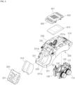
FIG. 1 is an exploded perspective view illustrating a brake dust collector in accordance with one embodiment of the present invention; -
FIG. 2 is a view illustrating a state where the brake dust collector in accordance with one embodiment of the present invention is assembled; -
FIG. 3 is an exploded perspective view illustrating a brake dust collector in accordance with another embodiment of the present invention; -
FIG. 4 is a perspective view illustrating a state where the brake dust collector in accordance with another embodiment of the present invention is assembled; and -
FIG. 5 is a side view illustrating a state where the brake dust collector in accordance with another embodiment of the present invention is assembled. - Hereinafter, embodiments of the present invention will be described in detail with reference to the accompanying drawings. The following embodiments are provided to fully convey the present invention to a person having ordinary skill in the art. The present invention is not limited to the embodiments shown herein but may be embodied in other forms. The drawings may omit the illustration of parts not related to the description in order to clarify the present invention, and slightly exaggerate the size of the components to help understanding.
-
FIG. 1 is an exploded perspective view illustrating a brake dust, andFIG. 2 is a view illustrating a state where the brake dust collector is coupled. - Referring to
FIGS. 1 and2 , a brake dust collector includes abrake pad 100, ahousing 200, and amain filter module 300. - More specifically, the
brake pad 100 includes apiston 110, aguide pin 120, and apad spring 130 disposed on both sides of a disc D. The disc D rotates together with a wheel, and thebrake pad 100 is movable into close contact with or to be separated from both sides of the disc D by means of thepiston 110. When thebrake pad 100 is in contact with the disc D, it provides a braking force to the disc D. - Herein, the
piston 110 may move thebrake pad 100 in a forward direction and a backward direction, that is, towards and away from the disc D. In this regard, various methods including a hydraulic method or an electromechanical method may be employed, and althoughFIG. 1 illustrates that thepiston 110 is coupled to thebrake pad 100, thepiston 110 may be installed by being inserted into a groove provided inside thehousing 200. - In addition, the
guide pin 120 is coupled to thebrake pad 100 by penetrating both the upper sides of thebrake pad 100. Theguide pin 120 is longitudinally placed in the forward and backward direction of thebrake pad 100, and thus guides the forward and backward movement of thebrake pad 100. - In addition, although the
guide pin 120 is illustrated to be coupled to thebrake pad 100 inFIG. 1 , theguide pin 120 may be actually formed, as illustrated inFIG. 2 , with one end penetrating thehousing 200 and supported inside thehousing 200 and the other end supported by being exposed to the outside of thehousing 200. - Herein, the
guide pin 120 may be fixed by a fastener such as afixing clip 121 to be prevented from being separated from thehousing 200. - In addition, the
pad spring 130 may be a leaf spring where a plurality of bent portions are formed. Thepad spring 130 is installed on each of both ends of thebrake pad 100 to cover a part of theguide pin 120 and support a lower part of thebrake pad 100. Thus, thepad spring 130 not only supports thebrake pad 100, but also enables the smooth forward and backward movement of thebrake pad 100. - Meanwhile, the
brake pad 100 is not limited to the above-described configuration and structure but may apply various methods of providing a braking force to the disc D by simultaneously being in close contact with or separated from both sides of the disc D. - In addition, the
brake pad 100 may apply brake structures with various response types. - Meanwhile, the
housing 200 has a cover shape capable of covering a part of the disc D, while thebrake pad 100 is installed on an inner side or accommodated in thehousing 200. and thehousing 200 includes a first or leadingportion 210 formed on one side, a second or trailingportion 220 formed on the other side, and awindow 230 formed between the leadingportion 210 and the trailingportion 220. For example, thehousing 200 may be formed in an arc shape extending along a circumferential direction, wherein the leadingportion 210 is formed in a first end region of thehousing 200 with respect to the circumferential direction, and the trailing portion is formed in an opposite second end region of thehousing 200 with respect to the circumferential direction. - In addition, the
housing 200 may be formed in various structures including a monoblock type where the leadingportion 210, the trailingportion 220, and thewindow 230 are integrally formed. - More specifically, if the disc D rotates in a predefined rotation direction, e.g., in the counterclockwise direction, as illustrated in
FIG. 2 , a point on the circumference of the disc D enters thehousing 200 at the leadingportion 210, passes thewindow 230, and exits thehousing 200 at the trailingportion 220. In the view illustrated inFIG. 2 , the leadingportion 210 and the trailingportion 220 are on the right side and the left side, respectively, and thewindow 230 is formed between the leadingportion 210 and the trailingportion 220. - In the example of
FIG. 2 , the trailingportion 220 is formed to extend in a lower left direction. Generally, the trailingportion 220 includes amain fastening portion 221 to which themain filter module 300 is fastened. - The
main fastening portion 220 includes amain fastening hole 221a, which is formed to penetrate toward the disc D, and afastening bracket 221b for mounting themain filter module 300. As shown inFig. 1 , themain fastening hole 221a forms an opening in the trailingportion 220 exposing the disc D. - In addition, although the
fastening bracket 221b may be embodied in various shapes, when thehousing 200 is mounted in a vehicle and the like, thefastening bracket 221b may be formed on one side, in particular, a lateral side of themain fastening hole 221a in order to be prevented from exposure to the outside. - Meanwhile, the
main filter module 300 includes amain filter 310, which covers themain fastening hole 221a and has a cover shape corresponding to a shape of the trailingportion 220. Amain filter cover 320 may be configured to support and protect themain filter 310. - In addition, although various known materials are applicable, the
main filter 310 may be made of a corrosion-resistant metal material and/or heat resistant metal material to minimize deformation due to an external force. For example, themain filter 310 may be made of stainless steel. - In addition, the
main filter cover 320 includes a multiple number of main flow holes 321, which are formed on an overall surface. Themain filter cover 320 may be formed of a metal material to protect and support themain filter 310. Themain filter cover 320 may, for example, have substantially an arc shape. As exemplarily shown inFIGS. 1 and2 , themain filter cover 320 may include an outer circumferential portion, which may, for example, be arc shaped, and planar portions protruding from the outer circumferential portion, wherein the planar portions extend parallel to each other and transverse to the outer circumferential portion. When mounted to thehousing 200, the outer circumferential portion extends parallel to an outer circumferential surface of the disc D, and the planar portions extend in a direction parallel to both side surfaces of the disc D. - Herein, the main flow holes 321 may be formed to have a sufficient area so that various fluids can smoothly pass therethrough.
- In addition, when the main flow holes 321 are formed in an outer circumferential portion that is a surface located on an outer circumferential surface of the disc D, the main flow holes 321 may be formed to be tilted downward from the inner side to the outer side. That is, assuming that an inner surface of the outer circumferential portion and an outer surface of outer circumferential portion are parallel, a central axis of the main flow holes 321 extends non-perpendicular to the inner and outer surface of the outer circumferential portion. More generally, the central axes of the main flow holes 321 may be inclined so that a non-perpendicular angle exists between the respective central axis and a tangent to the circumferential surface of the disc D at a position where the central axis intersects the circumferential surface of the disc D. In particular, the central axes of the main flow holes 321 may be inclined in a direction away from the leading
portion 210. In other words, an angle at a side of the central axis facing the trailingportion 220 may be smaller than 90°, while an angle at a side of the central axis facing the leadingportion 210 may be greater than 90°.Therefore, the main flow holes 321 may correspond to a direction of an air flow generated by the rotation of the disc D so that heat generated by the braking operation may be discharged more effectively. - In addition, a bush structure (not illustrated) may be applied to a location corresponding to the
fastening bracket 221b in order to bolt themain filter cover 320 to thefastening bracket 221b. Generally, themain filter cover 320 may be mounted to thehousing 200, in particular, detachably mounted to thehousing 200. For example, as shown inFIG. 2 , themain filter cover 320 may be mounted to themain fastening portion 221. Irrespective of how themain filter cover 320 is fixed, themain filter cover 320 may be mounted such that an end side of themain filter cover 320 is positioned at a predetermined distance from thehousing 200 or themain fastening portion 221. For example, themain filter cover 320 may be positioned such that a gap extends between an edge of themain filter cover 320 and at least a part of themain fastening portion 221, as schematically shown inFig. 2 . - In addition, in order to sufficiently discharge heat generated by friction between the
brake pad 100 and the disc D to the outside, when themain filter module 300 is mounted on themain fastening portion 220, a predetermined gap may be formed so that each of the upper and lower ends does not come into close contact with themain fastening portion 220. - Accordingly, in the brake dust collector, the
main filter module 300 may be easily detached from thehousing 200, and themain filter 310 may also be cleansed by high-pressure washing liquid flowing into the main flow holes 321, while themain filter module 300 is mounted on thehousing 200. - In addition, in the brake dust collector, since the
main filter module 300 is mounted on the side of the trailingportion 220, although a separate air flow control element is omitted as illustrated inFIG. 2 , the air flow generated by the rotation of the disc D effectively guides dust, which is generated by friction between thebrake pad 100 and the disc D, to the inner side of themain filter 310, so that dust collection efficiency may be improved. - In addition, in the brake dust collector, the stiffness of the
housing 200 may be further improved since the trailingportion 220 is formed to extend to mount themain filter module 300 and themain filter module 300 is bolted thereto. - Meanwhile,
FIG. 3 is an exploded perspective view illustrating a further brake dust collector.FIG. 4 is a perspective view illustrating a state where the brake dust collector is coupled.FIG. 5 is a side view illustrating a state where the brake dust collector is coupled. - Referring to
FIGS. 3 to 5 , the brake dust collector may further include asub filter module 400 and has the same or similar configuration to the above-described embodiment. - To this end, in the
housing 200, asub fastening portion 231 detachable from thesub filter module 400 is additionally formed by including asub fastening hole 231a formed to penetrate to the side of the disc D in thewindow 230. That is, thewindow 230 of thehousing 200 includes thesub fastening hole 231a through which the disc D is exposed. - More specifically, as illustrated in
FIG. 3 , thebrake pad 100 may be installed in thehousing 200 more easily since thesub fastening hole 231a is formed above thebrake pad 100 embedded or accommodated in thehousing 200. In other words, thesub fastening hole 231a is formed on a circumferential position corresponding to the position of thebrake pad 100. - Meanwhile, the
sub filter module 400 includes asub filter 410, which covers thesub fastening hole 231a and has a cover shape corresponding to the shape of thewindow 230. Thesub filter module 400 also includes asub filter cover 420 configured to support and protect thesub filter 410. - Herein, although various known materials are applicable, the
sub filter 410 may be made of a corrosion-resistant metal or heat-resistant metal material to minimize deformation due to an external force. For example, thesub filter 410 may be made of stainless steel. - In addition, the
sub filter cover 420 includes a multiple number of sub flow holes 421 formed on an overall surface and aflow passage 422. Thesub filter cover 420 is formed on a lower side to extend to be recessed in a direction from the leadingportion 210 to the trailingportion 220. Thesub filter cover 420 is formed of a metal material to protect and support thesub filter 410, and may be bolted to thesub fastening portion 231. - Herein, the sub flow holes 421 may be formed to have a sufficient area so that various fluids can pass through smoothly. For example, the sub flow holes 421 may be in the form of longitudinal slits extending substantially along the circumferential direction of the
housing 200, as shown inFIG. 4 . As further shown inFIG. 4 , theoptional flow passage 422 may be defined by a recess or formed in a surface of thesub filter cover 420 facing thewindow 230, e.g., in a bottom surface of thesub filter cover 422. Generally, thesub filter cover 420 may be mounted with at least part of the bottom surface of thesub filter cover 420 at predetermined distance from thehousing 200 or thesub fastening portion 231. - In addition, through the
flow passage 422, thesub filter module 400 does not completely close thesub fastening hole 231a but forms a predetermined gap on the side of the leadingportion 210 and on the side of the trailingportion 220. As a result, the heat dissipation performance may be further improved for heat generated during friction between thebrake pad 100 and the disc D. - Accordingly, as illustrated in
FIG. 5 , the brake dust collector may reduce dust generated by friction between thebrake pad 100 and the disc D more effectively through themain filter module 300 and thesub filter module 400. - In addition, in the brake dust collector, the
main filter module 300 and thesub filter module 400 may be easily detached from thehousing 200, and themain filter 310 and thesub filter 410 may also be cleansed by high-pressure washing liquid flowing into the main flow holes 321 and the sub flow holes 421, while themain filter module 300 and thesub filter module 400 are mounted on thehousing 200, so that filter life extension and efficiency improvement may be expected. - A brake dust collector in accordance with the present invention can effectively collect dust that is generated by a friction force between a disc and a brake pad and discharged to the outside of a housing.
- The brake dust collector described above can collect dust through a tangential air flow generated by rotation of a disc without a separate flow control element for dust guide.
- The brake dust collector described above can improve maintainability by forming a filter module to be detachable.
- The brake dust collector described above can not only reinforce stiffness of a housing itself but also prevent the deterioration in aesthetics due to a filter module since the filter module is formed to be detachable from a portion formed to extend to a trailing portion side of the housing.
- The brake dust collector described above can improve filter efficiency and extend filter life by providing an additional filter module on a window side.
- The brake dust collector described above can prevent decline of filter efficiency by enabling a filter to be cleansed by washing liquid and the like even in a state where a filter module is mounted.
the brake dust collector described above can further improve heat dissipation performance in exhausting heat caused by friction between a disc and a brake pad to the outside of a housing. - Although a few embodiments of the present invention have been shown and described, it would be appreciated by those skilled in the art that changes may be made in these embodiments without departing from the scope of the invention which is defined in the claims.
Claims (14)
- A brake dust collector comprising:a pair of brake pads (100) that are respectively disposed on both sides of a disc (D) configured to rotate together with a wheel, the pair of brake pads (100) being movable into contact with or to be separated from the disc (D);a housing (200) accommodating the brake pads (100) and being configured to cover at least a part of the disc (D);a main fastening portion (221) having a main fastening hole (221a) formed to penetrate a trailing portion of the housing (200) in a radial direction; anda main filter module (300) including a main filter (310) provided in the main fastening hole (221a) and a main filter cover (320) through which at least one main flow hole (321) is formed to penetrate and which is configured to support the main filter (310),wherein the main filter module (300) is configured to be detachable from the main fastening portion (221).
- The brake dust collector of claim 1, wherein the main filter module (300) is bolted to the main fastening portion (221).
- The brake dust collector of claim 2, wherein the main fastening portion (221) further comprises:a fastening bracket (221b) formed to protrude in the radial direction; anda fastening hole formed to penetrate the fastening bracket (221b) in a direction transverse to the disc (D),wherein the main filter module (300) and the fastening bracket (221b) are bolted with a bolt passing through the fastening hole of the fastening bracket (221b).
- The brake dust collector of any one of the preceding claims, wherein the main filter (310) is made of a metal with corrosion resistance and heat resistance.
- The brake dust collector of any one of the preceding claims, wherein the main filter cover (320) is mounted such that an end side of the main filter cover (320) is positioned at a predetermined distance from the housing (200) or the main fastening portion (221).
- The brake dust collector of any one of the preceding claims, wherein the main filter cover (320) comprises an outer circumferential portion formed in a direction parallel to an outer circumferential surface of the disc (D) and a pair of planar portions disposed in a direction parallel to both side surfaces of the disc (D), and
the main flow hole (321) is formed to penetrate at least one of the outer circumferential portion or the pair of planar portions. - The brake dust collector of claim 6, wherein the main flow hole (321) is provided in the outer circumferential portion and is formed to be inclined such that a non-perpendicular angle exists between a central axis of the main flow hole (321) and a tangent to the outer circumferential surface of the disc (D).
- The brake dust collector of any one of the preceding claims, wherein the housing (200) is formed as a monoblock.
- A brake dust collector of any one of the preceding claims, further comprising:a sub fastening portion (231) having a sub fastening hole (231a) formed to penetrate a window (230) of the housing (200) in the radial direction; anda sub filter module (400) provided to be detachable from the sub fastening portion (231) and including a sub filter (410) provided in the sub fastening hole (231a) and a sub filter cover (420) configured to support the sub filter (410).
- The brake dust collector of claim 9, wherein the sub filter module (400) is bolted to the sub fastening portion (231).
- The brake dust collector of claim 9 or 10, wherein the sub filter cover (420) further comprises a rib formed to protrude from an outer surface and a fastening hole formed to penetrate the rib, and
the sub filter module (400) and the rib are coupled to each other and the sub filter module (400) is bolted to the housing (200) or the sub fastening portion (231) by a bolt member penetrating the fastening hole formed in the rib. - The brake dust collector of any one of claims 9 to 11, wherein the sub filter (410) is made of a metal with corrosion resistance and heat resistance.
- The brake dust collector of any one of claims 9 to 12, wherein the sub filter cover (420) is mounted with at least a part of a bottom surface at a predetermined space from the housing (200) or the sub fastening portion (231).
- The brake dust collector of claim 13, wherein the sub filter cover (420) comprises a flow passage (422) formed to be recessed on the bottom surface and formed to extend from a leading portion to a trailing portion of the sub filter cover (420).
Applications Claiming Priority (1)
| Application Number | Priority Date | Filing Date | Title |
|---|---|---|---|
| KR1020230002867A KR20240111146A (en) | 2023-01-09 | 2023-01-09 | Brake dust collector |
Publications (2)
| Publication Number | Publication Date |
|---|---|
| EP4397881A1 true EP4397881A1 (en) | 2024-07-10 |
| EP4397881B1 EP4397881B1 (en) | 2025-01-29 |
Family
ID=88021118
Family Applications (1)
| Application Number | Title | Priority Date | Filing Date |
|---|---|---|---|
| EP23197035.1A Active EP4397881B1 (en) | 2023-01-09 | 2023-09-13 | Brake dust collector |
Country Status (3)
| Country | Link |
|---|---|
| US (1) | US20240229877A1 (en) |
| EP (1) | EP4397881B1 (en) |
| KR (1) | KR20240111146A (en) |
Cited By (1)
| Publication number | Priority date | Publication date | Assignee | Title |
|---|---|---|---|---|
| WO2026057220A1 (en) * | 2024-09-11 | 2026-03-19 | Kb Intellectual Property Gmbh & Co. Kg | Brake carrier for a disc brake |
Families Citing this family (1)
| Publication number | Priority date | Publication date | Assignee | Title |
|---|---|---|---|---|
| DE102024118205A1 (en) * | 2024-06-27 | 2025-12-31 | Hengst Se | Brake dust filter for a disc brake |
Citations (8)
| Publication number | Priority date | Publication date | Assignee | Title |
|---|---|---|---|---|
| DE8428099U1 (en) * | 1984-09-24 | 1985-01-03 | Lucas Industries P.L.C., Birmingham, West Midlands | PARTIAL DISC BRAKE FOR VEHICLES |
| US20090071767A1 (en) * | 2007-08-10 | 2009-03-19 | Richard Arnold Bass | Disc brake caliper body and a disc brake caliper comprising such a body |
| US20100065387A1 (en) * | 2006-11-03 | 2010-03-18 | Konstantinos Tsiberidis | Brake dust collecting device |
| US20170198772A1 (en) * | 2016-01-13 | 2017-07-13 | Tallano Technologie | Particle Trapping Brake Assembly With Deflector |
| US20180031059A1 (en) * | 2016-07-29 | 2018-02-01 | Joseph Gelb | Brake Pad Waste Collector |
| KR102112358B1 (en) * | 2018-08-07 | 2020-05-18 | 서한산업(주) | Dust Collecting Apparatus for Brake Disc |
| DE102020118880A1 (en) * | 2020-07-16 | 2022-01-20 | Mann+Hummel Gmbh | Caliper bracket, disc brake assembly, use of a caliper bracket and method of directing air |
| DE102021102775A1 (en) * | 2021-02-05 | 2022-08-11 | Mann+Hummel Gmbh | Filter housing of a brake dust particle filter for a brake disc assembly |
Family Cites Families (6)
| Publication number | Priority date | Publication date | Assignee | Title |
|---|---|---|---|---|
| US20070000740A1 (en) | 2005-04-11 | 2007-01-04 | Simon Raab | Brake pad dust collector or diverter |
| DE102017008423A1 (en) | 2017-09-08 | 2019-03-14 | Mann+Hummel Gmbh | Brake dust particle filter and disc brake assembly with a brake dust particulate filter |
| DE102018127039A1 (en) | 2018-10-30 | 2020-04-30 | Mann+Hummel Gmbh | Brake dust particle filter, brake caliper and disc brake assembly |
| KR102538298B1 (en) | 2020-12-29 | 2023-05-30 | 한국세라믹기술원 | Dust collecting apparatus for capturing dust generated in break apparatus of transportation means and manufacturing method of dust collecting apparatus |
| JP7542727B2 (en) | 2021-04-13 | 2024-08-30 | 日立Astemo株式会社 | Disc brake |
| DE102021114797B4 (en) | 2021-06-09 | 2024-11-07 | Mann+Hummel Gmbh | brake dust particle filter with a filter insert |
-
2023
- 2023-01-09 KR KR1020230002867A patent/KR20240111146A/en active Pending
- 2023-09-13 EP EP23197035.1A patent/EP4397881B1/en active Active
- 2023-10-17 US US18/380,811 patent/US20240229877A1/en active Pending
Patent Citations (8)
| Publication number | Priority date | Publication date | Assignee | Title |
|---|---|---|---|---|
| DE8428099U1 (en) * | 1984-09-24 | 1985-01-03 | Lucas Industries P.L.C., Birmingham, West Midlands | PARTIAL DISC BRAKE FOR VEHICLES |
| US20100065387A1 (en) * | 2006-11-03 | 2010-03-18 | Konstantinos Tsiberidis | Brake dust collecting device |
| US20090071767A1 (en) * | 2007-08-10 | 2009-03-19 | Richard Arnold Bass | Disc brake caliper body and a disc brake caliper comprising such a body |
| US20170198772A1 (en) * | 2016-01-13 | 2017-07-13 | Tallano Technologie | Particle Trapping Brake Assembly With Deflector |
| US20180031059A1 (en) * | 2016-07-29 | 2018-02-01 | Joseph Gelb | Brake Pad Waste Collector |
| KR102112358B1 (en) * | 2018-08-07 | 2020-05-18 | 서한산업(주) | Dust Collecting Apparatus for Brake Disc |
| DE102020118880A1 (en) * | 2020-07-16 | 2022-01-20 | Mann+Hummel Gmbh | Caliper bracket, disc brake assembly, use of a caliper bracket and method of directing air |
| DE102021102775A1 (en) * | 2021-02-05 | 2022-08-11 | Mann+Hummel Gmbh | Filter housing of a brake dust particle filter for a brake disc assembly |
Cited By (1)
| Publication number | Priority date | Publication date | Assignee | Title |
|---|---|---|---|---|
| WO2026057220A1 (en) * | 2024-09-11 | 2026-03-19 | Kb Intellectual Property Gmbh & Co. Kg | Brake carrier for a disc brake |
Also Published As
| Publication number | Publication date |
|---|---|
| KR20240111146A (en) | 2024-07-16 |
| EP4397881B1 (en) | 2025-01-29 |
| US20240229877A1 (en) | 2024-07-11 |
Similar Documents
| Publication | Publication Date | Title |
|---|---|---|
| EP4397881B1 (en) | Brake dust collector | |
| US4485897A (en) | Disc brake system | |
| KR102815391B1 (en) | Braking system with centrifugal suction in the grooves of the lining | |
| CN105570358B (en) | Protective device for brake disc | |
| EP3470700A1 (en) | Disc brake device | |
| RU2317453C2 (en) | Protective shield for disk brake and disk brake unit | |
| KR20240111157A (en) | Brake dust collector | |
| KR20210143210A (en) | Brake system with air blown into grooves in the lining | |
| JP2005172226A (en) | Structure of brake dust cover of automobile | |
| KR20230039600A (en) | Brake caliper support, disc brake assembly, use of brake caliper support, and air guiding method | |
| JPH07332406A (en) | Disc brake | |
| US20250012333A1 (en) | Disc brake arrangement and brake dust particle filter | |
| EP4397879A1 (en) | Brake dust collector | |
| US20240240680A1 (en) | Caliper brake | |
| EP4480764A1 (en) | Brake dust collector | |
| KR20240178627A (en) | Brake dust collector | |
| EP4481223B1 (en) | Vehicle brake assembly configured for collecting brake dust | |
| EP4495448A1 (en) | Brake caliper | |
| KR20240178618A (en) | Brake dust collector | |
| JP2002250382A (en) | Disc brake cooling system | |
| KR102959461B1 (en) | Dust removal system for drum brake | |
| KR20250028085A (en) | Brake dust collector | |
| HK40055151B (en) | Braking system with centrifugal suction in the groove of the lining | |
| JPS5857528A (en) | disc brake | |
| HK40055151A (en) | Braking system with centrifugal suction in the groove of the lining |
Legal Events
| Date | Code | Title | Description |
|---|---|---|---|
| PUAI | Public reference made under article 153(3) epc to a published international application that has entered the european phase |
Free format text: ORIGINAL CODE: 0009012 |
|
| STAA | Information on the status of an ep patent application or granted ep patent |
Free format text: STATUS: REQUEST FOR EXAMINATION WAS MADE |
|
| 17P | Request for examination filed |
Effective date: 20230913 |
|
| AK | Designated contracting states |
Kind code of ref document: A1 Designated state(s): AL AT BE BG CH CY CZ DE DK EE ES FI FR GB GR HR HU IE IS IT LI LT LU LV MC ME MK MT NL NO PL PT RO RS SE SI SK SM TR |
|
| GRAP | Despatch of communication of intention to grant a patent |
Free format text: ORIGINAL CODE: EPIDOSNIGR1 |
|
| STAA | Information on the status of an ep patent application or granted ep patent |
Free format text: STATUS: GRANT OF PATENT IS INTENDED |
|
| INTG | Intention to grant announced |
Effective date: 20241021 |
|
| GRAS | Grant fee paid |
Free format text: ORIGINAL CODE: EPIDOSNIGR3 |
|
| GRAA | (expected) grant |
Free format text: ORIGINAL CODE: 0009210 |
|
| STAA | Information on the status of an ep patent application or granted ep patent |
Free format text: STATUS: THE PATENT HAS BEEN GRANTED |
|
| AK | Designated contracting states |
Kind code of ref document: B1 Designated state(s): AL AT BE BG CH CY CZ DE DK EE ES FI FR GB GR HR HU IE IS IT LI LT LU LV MC ME MK MT NL NO PL PT RO RS SE SI SK SM TR |
|
| REG | Reference to a national code |
Ref country code: GB Ref legal event code: FG4D |
|
| REG | Reference to a national code |
Ref country code: CH Ref legal event code: EP |
|
| REG | Reference to a national code |
Ref country code: DE Ref legal event code: R096 Ref document number: 602023001901 Country of ref document: DE |
|
| REG | Reference to a national code |
Ref country code: IE Ref legal event code: FG4D |
|
| REG | Reference to a national code |
Ref country code: NL Ref legal event code: MP Effective date: 20250129 |
|
| PG25 | Lapsed in a contracting state [announced via postgrant information from national office to epo] |
Ref country code: NL Free format text: LAPSE BECAUSE OF FAILURE TO SUBMIT A TRANSLATION OF THE DESCRIPTION OR TO PAY THE FEE WITHIN THE PRESCRIBED TIME-LIMIT Effective date: 20250129 |
|
| PG25 | Lapsed in a contracting state [announced via postgrant information from national office to epo] |
Ref country code: RS Free format text: LAPSE BECAUSE OF FAILURE TO SUBMIT A TRANSLATION OF THE DESCRIPTION OR TO PAY THE FEE WITHIN THE PRESCRIBED TIME-LIMIT Effective date: 20250429 |
|
| PG25 | Lapsed in a contracting state [announced via postgrant information from national office to epo] |
Ref country code: FI Free format text: LAPSE BECAUSE OF FAILURE TO SUBMIT A TRANSLATION OF THE DESCRIPTION OR TO PAY THE FEE WITHIN THE PRESCRIBED TIME-LIMIT Effective date: 20250129 |
|
| PG25 | Lapsed in a contracting state [announced via postgrant information from national office to epo] |
Ref country code: PL Free format text: LAPSE BECAUSE OF FAILURE TO SUBMIT A TRANSLATION OF THE DESCRIPTION OR TO PAY THE FEE WITHIN THE PRESCRIBED TIME-LIMIT Effective date: 20250129 |
|
| PG25 | Lapsed in a contracting state [announced via postgrant information from national office to epo] |
Ref country code: ES Free format text: LAPSE BECAUSE OF FAILURE TO SUBMIT A TRANSLATION OF THE DESCRIPTION OR TO PAY THE FEE WITHIN THE PRESCRIBED TIME-LIMIT Effective date: 20250129 |
|
| REG | Reference to a national code |
Ref country code: LT Ref legal event code: MG9D |
|
| PG25 | Lapsed in a contracting state [announced via postgrant information from national office to epo] |
Ref country code: IS Free format text: LAPSE BECAUSE OF FAILURE TO SUBMIT A TRANSLATION OF THE DESCRIPTION OR TO PAY THE FEE WITHIN THE PRESCRIBED TIME-LIMIT Effective date: 20250529 Ref country code: NO Free format text: LAPSE BECAUSE OF FAILURE TO SUBMIT A TRANSLATION OF THE DESCRIPTION OR TO PAY THE FEE WITHIN THE PRESCRIBED TIME-LIMIT Effective date: 20250429 |
|
| REG | Reference to a national code |
Ref country code: AT Ref legal event code: MK05 Ref document number: 1763713 Country of ref document: AT Kind code of ref document: T Effective date: 20250129 |
|
| PG25 | Lapsed in a contracting state [announced via postgrant information from national office to epo] |
Ref country code: HR Free format text: LAPSE BECAUSE OF FAILURE TO SUBMIT A TRANSLATION OF THE DESCRIPTION OR TO PAY THE FEE WITHIN THE PRESCRIBED TIME-LIMIT Effective date: 20250129 |
|
| PG25 | Lapsed in a contracting state [announced via postgrant information from national office to epo] |
Ref country code: PT Free format text: LAPSE BECAUSE OF FAILURE TO SUBMIT A TRANSLATION OF THE DESCRIPTION OR TO PAY THE FEE WITHIN THE PRESCRIBED TIME-LIMIT Effective date: 20250529 Ref country code: LV Free format text: LAPSE BECAUSE OF FAILURE TO SUBMIT A TRANSLATION OF THE DESCRIPTION OR TO PAY THE FEE WITHIN THE PRESCRIBED TIME-LIMIT Effective date: 20250129 |
|
| PG25 | Lapsed in a contracting state [announced via postgrant information from national office to epo] |
Ref country code: BG Free format text: LAPSE BECAUSE OF FAILURE TO SUBMIT A TRANSLATION OF THE DESCRIPTION OR TO PAY THE FEE WITHIN THE PRESCRIBED TIME-LIMIT Effective date: 20250129 Ref country code: GR Free format text: LAPSE BECAUSE OF FAILURE TO SUBMIT A TRANSLATION OF THE DESCRIPTION OR TO PAY THE FEE WITHIN THE PRESCRIBED TIME-LIMIT Effective date: 20250430 |
|
| PG25 | Lapsed in a contracting state [announced via postgrant information from national office to epo] |
Ref country code: AT Free format text: LAPSE BECAUSE OF FAILURE TO SUBMIT A TRANSLATION OF THE DESCRIPTION OR TO PAY THE FEE WITHIN THE PRESCRIBED TIME-LIMIT Effective date: 20250129 |
|
| PG25 | Lapsed in a contracting state [announced via postgrant information from national office to epo] |
Ref country code: SE Free format text: LAPSE BECAUSE OF FAILURE TO SUBMIT A TRANSLATION OF THE DESCRIPTION OR TO PAY THE FEE WITHIN THE PRESCRIBED TIME-LIMIT Effective date: 20250129 |
|
| PG25 | Lapsed in a contracting state [announced via postgrant information from national office to epo] |
Ref country code: SM Free format text: LAPSE BECAUSE OF FAILURE TO SUBMIT A TRANSLATION OF THE DESCRIPTION OR TO PAY THE FEE WITHIN THE PRESCRIBED TIME-LIMIT Effective date: 20250129 |
|
| PG25 | Lapsed in a contracting state [announced via postgrant information from national office to epo] |
Ref country code: DK Free format text: LAPSE BECAUSE OF FAILURE TO SUBMIT A TRANSLATION OF THE DESCRIPTION OR TO PAY THE FEE WITHIN THE PRESCRIBED TIME-LIMIT Effective date: 20250129 |
|
| PGFP | Annual fee paid to national office [announced via postgrant information from national office to epo] |
Ref country code: DE Payment date: 20250609 Year of fee payment: 3 |
|
| PG25 | Lapsed in a contracting state [announced via postgrant information from national office to epo] |
Ref country code: IT Free format text: LAPSE BECAUSE OF FAILURE TO SUBMIT A TRANSLATION OF THE DESCRIPTION OR TO PAY THE FEE WITHIN THE PRESCRIBED TIME-LIMIT Effective date: 20250129 |
|
| REG | Reference to a national code |
Ref country code: DE Ref legal event code: R026 Ref document number: 602023001901 Country of ref document: DE |
|
| PG25 | Lapsed in a contracting state [announced via postgrant information from national office to epo] |
Ref country code: EE Free format text: LAPSE BECAUSE OF FAILURE TO SUBMIT A TRANSLATION OF THE DESCRIPTION OR TO PAY THE FEE WITHIN THE PRESCRIBED TIME-LIMIT Effective date: 20250129 Ref country code: CZ Free format text: LAPSE BECAUSE OF FAILURE TO SUBMIT A TRANSLATION OF THE DESCRIPTION OR TO PAY THE FEE WITHIN THE PRESCRIBED TIME-LIMIT Effective date: 20250129 |
|
| PG25 | Lapsed in a contracting state [announced via postgrant information from national office to epo] |
Ref country code: RO Free format text: LAPSE BECAUSE OF FAILURE TO SUBMIT A TRANSLATION OF THE DESCRIPTION OR TO PAY THE FEE WITHIN THE PRESCRIBED TIME-LIMIT Effective date: 20250129 |
|
| PLBI | Opposition filed |
Free format text: ORIGINAL CODE: 0009260 |
|
| PG25 | Lapsed in a contracting state [announced via postgrant information from national office to epo] |
Ref country code: SK Free format text: LAPSE BECAUSE OF FAILURE TO SUBMIT A TRANSLATION OF THE DESCRIPTION OR TO PAY THE FEE WITHIN THE PRESCRIBED TIME-LIMIT Effective date: 20250129 |
|
| REG | Reference to a national code |
Ref country code: CH Ref legal event code: L10 Free format text: ST27 STATUS EVENT CODE: U-0-0-L10-L00 (AS PROVIDED BY THE NATIONAL OFFICE) Effective date: 20251029 |
|
| PLAX | Notice of opposition and request to file observation + time limit sent |
Free format text: ORIGINAL CODE: EPIDOSNOBS2 |
|
| 26 | Opposition filed |
Opponent name: VRI-PATENT MONITORING ASSOCIATION Effective date: 20251017 |
|
| PLBB | Reply of patent proprietor to notice(s) of opposition received |
Free format text: ORIGINAL CODE: EPIDOSNOBS3 |
|
| PLAB | Opposition data, opponent's data or that of the opponent's representative modified |
Free format text: ORIGINAL CODE: 0009299OPPO |
|
| REG | Reference to a national code |
Ref country code: CH Ref legal event code: L10 Free format text: ST27 STATUS EVENT CODE: U-0-0-L10-L00 (AS PROVIDED BY THE NATIONAL OFFICE) Effective date: 20260402 |
|
| R26 | Opposition filed (corrected) |
Opponent name: VRI-PATENT MONITORING ASSOCIATION Effective date: 20251017 |