EP4397879A1 - Brake dust collector - Google Patents
Brake dust collector Download PDFInfo
- Publication number
- EP4397879A1 EP4397879A1 EP23190525.8A EP23190525A EP4397879A1 EP 4397879 A1 EP4397879 A1 EP 4397879A1 EP 23190525 A EP23190525 A EP 23190525A EP 4397879 A1 EP4397879 A1 EP 4397879A1
- Authority
- EP
- European Patent Office
- Prior art keywords
- pad
- brake
- filter module
- dust collector
- housing
- Prior art date
- Legal status (The legal status is an assumption and is not a legal conclusion. Google has not performed a legal analysis and makes no representation as to the accuracy of the status listed.)
- Granted
Links
Images



Classifications
-
- F—MECHANICAL ENGINEERING; LIGHTING; HEATING; WEAPONS; BLASTING
- F16—ENGINEERING ELEMENTS AND UNITS; GENERAL MEASURES FOR PRODUCING AND MAINTAINING EFFECTIVE FUNCTIONING OF MACHINES OR INSTALLATIONS; THERMAL INSULATION IN GENERAL
- F16D—COUPLINGS FOR TRANSMITTING ROTATION; CLUTCHES; BRAKES
- F16D65/00—Parts or details
- F16D65/0031—Devices for retaining friction material debris, e.g. dust collectors or filters
-
- B—PERFORMING OPERATIONS; TRANSPORTING
- B01—PHYSICAL OR CHEMICAL PROCESSES OR APPARATUS IN GENERAL
- B01D—SEPARATION
- B01D46/00—Filters or filtering processes specially modified for separating dispersed particles from gases or vapours
- B01D46/0002—Casings; Housings; Frame constructions
- B01D46/0005—Mounting of filtering elements within casings, housings or frames
-
- B—PERFORMING OPERATIONS; TRANSPORTING
- B01—PHYSICAL OR CHEMICAL PROCESSES OR APPARATUS IN GENERAL
- B01D—SEPARATION
- B01D46/00—Filters or filtering processes specially modified for separating dispersed particles from gases or vapours
- B01D46/0002—Casings; Housings; Frame constructions
- B01D46/0013—Modules
-
- B—PERFORMING OPERATIONS; TRANSPORTING
- B01—PHYSICAL OR CHEMICAL PROCESSES OR APPARATUS IN GENERAL
- B01D—SEPARATION
- B01D46/00—Filters or filtering processes specially modified for separating dispersed particles from gases or vapours
- B01D46/10—Particle separators, e.g. dust precipitators, using filter plates, sheets or pads having plane surfaces
-
- F—MECHANICAL ENGINEERING; LIGHTING; HEATING; WEAPONS; BLASTING
- F16—ENGINEERING ELEMENTS AND UNITS; GENERAL MEASURES FOR PRODUCING AND MAINTAINING EFFECTIVE FUNCTIONING OF MACHINES OR INSTALLATIONS; THERMAL INSULATION IN GENERAL
- F16D—COUPLINGS FOR TRANSMITTING ROTATION; CLUTCHES; BRAKES
- F16D55/00—Brakes with substantially-radial braking surfaces pressed together in axial direction, e.g. disc brakes
- F16D55/02—Brakes with substantially-radial braking surfaces pressed together in axial direction, e.g. disc brakes with axially-movable discs or pads pressed against axially-located rotating members
- F16D55/22—Brakes with substantially-radial braking surfaces pressed together in axial direction, e.g. disc brakes with axially-movable discs or pads pressed against axially-located rotating members by clamping an axially-located rotating disc between movable braking members, e.g. movable brake discs or brake pads
- F16D55/224—Brakes with substantially-radial braking surfaces pressed together in axial direction, e.g. disc brakes with axially-movable discs or pads pressed against axially-located rotating members by clamping an axially-located rotating disc between movable braking members, e.g. movable brake discs or brake pads with a common actuating member for the braking members
- F16D55/225—Brakes with substantially-radial braking surfaces pressed together in axial direction, e.g. disc brakes with axially-movable discs or pads pressed against axially-located rotating members by clamping an axially-located rotating disc between movable braking members, e.g. movable brake discs or brake pads with a common actuating member for the braking members the braking members being brake pads
- F16D55/226—Brakes with substantially-radial braking surfaces pressed together in axial direction, e.g. disc brakes with axially-movable discs or pads pressed against axially-located rotating members by clamping an axially-located rotating disc between movable braking members, e.g. movable brake discs or brake pads with a common actuating member for the braking members the braking members being brake pads in which the common actuating member is moved axially, e.g. floating caliper disc brakes
- F16D55/2265—Brakes with substantially-radial braking surfaces pressed together in axial direction, e.g. disc brakes with axially-movable discs or pads pressed against axially-located rotating members by clamping an axially-located rotating disc between movable braking members, e.g. movable brake discs or brake pads with a common actuating member for the braking members the braking members being brake pads in which the common actuating member is moved axially, e.g. floating caliper disc brakes the axial movement being guided by one or more pins engaging bores in the brake support or the brake housing
- F16D55/227—Brakes with substantially-radial braking surfaces pressed together in axial direction, e.g. disc brakes with axially-movable discs or pads pressed against axially-located rotating members by clamping an axially-located rotating disc between movable braking members, e.g. movable brake discs or brake pads with a common actuating member for the braking members the braking members being brake pads in which the common actuating member is moved axially, e.g. floating caliper disc brakes the axial movement being guided by one or more pins engaging bores in the brake support or the brake housing by two or more pins
Definitions
- Embodiments of the present disclosure relate to a brake dust collector, and more particularly, to a brake dust collector for collecting dust caused by friction between a brake pad and a disc during a braking operation.
- pollutants emitted from vehicles may be largely classified into pollutants emitted from an exhaust system and pollutants emitted from a non-exhaust system.
- the pollutants emitted from the exhaust system are pollutants contained in exhaust gas, which is generated when an engine of a vehicle is driven, and are already subject to regulations, while the pollutants emitted from the non-exhaust system are expected to be subject to corresponding regulations.
- a fixed-type caliper brake including a monoblock caliper usually provides relatively stable braking power even in high-speed repetition
- vehicle models to which the fixed-type caliper brake is applied are relatively high-performance vehicles and a large amount of dust is generated between discs and brake pads, and thus a method of reducing the dust is required all the more urgently.
- the conventional dust collector is provided as a separate device for dust collection on one side of a caliper housing, which reduces aesthetics and also reduces maintainability because the device body should be removed from the vehicle to clean or replace the filter.
- a brake dust collector capable of effectively collecting dust that is generated by friction between a disc and a brake pad and discharged to the outside of a housing.
- a brake dust collector includes: a pad module including a pair of brake pads that are respectively disposed on both sides of a disc rotating together with a wheel and are in close contact with or separated from the disc according to a forward and backward movement of a piston; a housing provided to cover a part of the disc by forming a pad module seat provided between a leading portion and a trailing portion and to which the pad module is coupled, and filter module seats at inner sides of the leading portion and the trailing portion, respectively; and a filter module fixed to each of the filter module seats by a fastening member that penetrates and fastens from one side to the other side of the housing.
- the pad module may further include: pad springs provided between both ends of the brake pad and the pad module seat; a shim pad provided between the brake pad and the piston; and guide pins provided in guide holes formed at both sides of an upper portion of the brake pad and configured to guide the forward and backward movement of the brake pad.
- the piston may be installed in a piston insertion portion provided on the pad module seat, and the shim pad may be fastened to the brake pad.
- the housing may further include an exposure groove provided at an end of each of the leading portion and the trailing portion so that one end of the filter module is partially exposed.
- the filter module may be fixed to the filter module seat with an end of the pad module being spaced at a predetermined interval from the pad spring or may be fixed to the filter module seat with an end of the pad module being supported by the pad spring.
- the filter module may include fastening member through holes, which are penetrated by the fastening members at both ends, and may be fixed to the pad module seat by the fastening member fastening through a fastening member fastening hole provided on the pad module seat and the fastening member through hole.
- the fastening member may be provided with a bolt penetrating the fastening member fastening hole on one side and a nut fastened to the bolt exposed to the fastening member fastening hole on the other side.
- the filter module may include a filter made of metal with corrosion resistance and heat resistance.
- the housing may be provided as a monoblock further including at least one or more heat dissipation holes that are provided as a heat exhaust passage and a fluid flow passage, respectively, in the leading portion and the trailing portion.
- a brake dust collector includes: a pad module including a pair of brake pads that are respectively disposed on both sides of a disc rotating together with a wheel and are in close contact with or separated from the disc according to a forward and backward movement of a piston; a housing provided to cover a part of the disc by forming a pad module seat provided between a leading portion and a trailing portion and to which the pad module is coupled, and a filter module seat at an inner side of the trailing portion; and a filter module fixed to the filter module seat by a fastening member penetrating and fastening from one side to the other side of the housing through a fastening member fastening hole provided on the filter module seat.
- the housing may further include an exposure groove provided at an end of the trailing portion so that one end of the filter module is partially exposed.
- the housing may be provided as a monoblock further including at least one or more heat dissipation holes that are provided as a heat exhaust passage and a fluid flow passage on the filter module seat.
- the filter module may be fixed to the filter module seat at a predetermined interval from the pad module.
- the brake pad 110 includes a backplate provided on a side of the piston 130 and a friction layer provided to touch the disc D.
- the backplate and the friction layer may be integrally formed.
- the brake pad 110 includes a guide hole 111 penetrated by the guide pin 150 on both sides of an upper portion.
- the guide pin 150 includes a fixing member fastening hole 152 provided at a head 151 and a fixing member 153 such as a fixing pin and the like, which is inserted into the fixing member fastening hole 152 and prevents the guide pin 150 from being separated from the brake pad 110 and the housing 200.
- the housing 200 further includes the pad module seat 210 provided between the leading portion 201 and the trailing portion 202 to enable the pad module 100 to be inserted into the housing 200, filter module seats 220 formed to extend from both sides of an upper portion of the pad module seat 210 toward the leading portion 201 and the trailing portion 202, and fastening member fastening holes 230 provided at both ends of each of the filter module seats 220.
- a brake dust collector in accordance with another embodiment of the present disclosure may be provided with the filter module 300 in only one of the leading portion 201 or the trailing portion 202.
- the filter module 300 since the typical air flow generated by the rotation of the disc D is induced from the leading portion 201 to the trailing portion 202, the filter module 300 may be more advantageously provided in the trailing portion 202 than in the leading portion 201.
- the filter module seat 220, the exposure groove 221, and the fastening member fastening hole 230 which are intended to fasten the filter module 300 to the housing 200, may be provided on a side of the trailing portion 202, and may be omitted on a side of the leading portion 201.
- the brake dust collector in accordance with the present embodiment may further minimize stiffness degradation of the housing 200 caused by the filter module 300.
- a brake dust collector in accordance with the present embodiment can improve dust collection efficiency due to a filter module provided in each of a leading portion and a trailing portion.
- a brake dust collector in accordance with the present embodiment can collect dust through a tangential air flow generated by rotation of a disc without a separate flow control element for dust induction.
- a brake dust collector in accordance with the present embodiment can omit a device for dust collection separately from a housing and thus prevent decline of aesthetics.
- a brake dust collector in accordance with the present embodiment can minimize stiffness degradation of a housing caused by a filter module inserted into the housing.
Landscapes
- Engineering & Computer Science (AREA)
- General Engineering & Computer Science (AREA)
- Chemical & Material Sciences (AREA)
- Chemical Kinetics & Catalysis (AREA)
- Mechanical Engineering (AREA)
- Braking Arrangements (AREA)
Abstract
Description
- This application claims the benefit of
Korean Patent Application No. 10-2023-0002907, filed on January 9, 2023 - Embodiments of the present disclosure relate to a brake dust collector, and more particularly, to a brake dust collector for collecting dust caused by friction between a brake pad and a disc during a braking operation.
- As the importance of environmental protection is emphasized, environmental friendliness has become a big issue in the automobile industry, and regulations on pollutants emitted from automobiles are also being continuously strengthened.
- Meanwhile, pollutants emitted from vehicles may be largely classified into pollutants emitted from an exhaust system and pollutants emitted from a non-exhaust system. The pollutants emitted from the exhaust system are pollutants contained in exhaust gas, which is generated when an engine of a vehicle is driven, and are already subject to regulations, while the pollutants emitted from the non-exhaust system are expected to be subject to corresponding regulations.
- Specifically, among the pollutants emitted from the non-exhaust system, dust generated due to abrasion caused by a frictional force between a brake pad and a disc during vehicle braking contains a large amount of harmful substances, so that a method for minimizing the dust is required in line with the fact that regulations on harmful dust and fine dust are gradually tightening.
- In addition, since a fixed-type caliper brake including a monoblock caliper usually provides relatively stable braking power even in high-speed repetition, vehicle models to which the fixed-type caliper brake is applied are relatively high-performance vehicles and a large amount of dust is generated between discs and brake pads, and thus a method of reducing the dust is required all the more urgently.
- Meanwhile, in order to meet the requirement, the conventional dust collector is provided as a separate device for dust collection on one side of a caliper housing, which reduces aesthetics and also reduces maintainability because the device body should be removed from the vehicle to clean or replace the filter.
- Therefore, it is an aspect of the present disclosure to provide a brake dust collector capable of effectively collecting dust that is generated by friction between a disc and a brake pad and discharged to the outside of a housing.
- It is another aspect of the present disclosure to provide a brake dust collector capable of improving dust collection efficiency by filter modules provided in a leading portion and a trailing portion, respectively.
- It is still another aspect of the present disclosure to provide a brake dust collector capable of facilitating management of a filter module by enabling the filter module to be cleansed by washing liquid and the like even in a state where the filter module is mounted on a housing.
- It is yet another aspect of the present disclosure to provide a brake dust collector capable of collecting dust through a tangential air flow generated by rotation of a disc without a separate flow control element for dust induction.
- It is yet another aspect of the present disclosure to provide a brake dust collector capable of preventing deterioration in aesthetics by omitting a device for dust collection provided separately from a housing.
- It is yet another aspect of the present disclosure to provide a brake dust collector capable of minimizing stiffness degradation of a housing caused by a filter module inserted into the housing.
- Additional aspects of the disclosure will be set forth in part in the description which follows and, in part, will be obvious from the description, or may be learned by practice of the disclosure.
- In accordance with one embodiment of the present disclosure, a brake dust collector includes: a pad module including a pair of brake pads that are respectively disposed on both sides of a disc rotating together with a wheel and are in close contact with or separated from the disc according to a forward and backward movement of a piston; a housing provided to cover a part of the disc by forming a pad module seat provided between a leading portion and a trailing portion and to which the pad module is coupled, and filter module seats at inner sides of the leading portion and the trailing portion, respectively; and a filter module fixed to each of the filter module seats by a fastening member that penetrates and fastens from one side to the other side of the housing.
- The pad module may further include: pad springs provided between both ends of the brake pad and the pad module seat; a shim pad provided between the brake pad and the piston; and guide pins provided in guide holes formed at both sides of an upper portion of the brake pad and configured to guide the forward and backward movement of the brake pad.
- Each of the pad springs may include: a guide pin locking portion provided in an upper center part and locked to a center part of the guide pin; a housing locking portion provided at an upper end and locked to the housing; and pad supports provided on both sides of a lower end of the brake pad and configured to support each side of the lower end of the brake pad.
- The housing may further include: pad module exposure portions provided on both ends of the pad module seat to penetrate upwards, respectively; and a pad spring support provided at the pad module exposure portion and configured to seat the housing locking portion.
- The piston may be installed in a piston insertion portion provided on the pad module seat, and the shim pad may be fastened to the brake pad.
- The guide pin may include a fixing member fastening hole provided at a head side; and a fixing member inserted into the fixing member fastening hole to prevent the guide pin from being separated from the housing and the brake pad, and may be coupled to a guide pin fastening hole provided in the pad module seat and the guide hole.
- The housing may further include an exposure groove provided at an end of each of the leading portion and the trailing portion so that one end of the filter module is partially exposed.
- The filter module may be fixed to the filter module seat with an end of the pad module being spaced at a predetermined interval from the pad spring or may be fixed to the filter module seat with an end of the pad module being supported by the pad spring.
- The filter module may include fastening member through holes, which are penetrated by the fastening members at both ends, and may be fixed to the pad module seat by the fastening member fastening through a fastening member fastening hole provided on the pad module seat and the fastening member through hole.
- The fastening member may be provided with a bolt penetrating the fastening member fastening hole on one side and a nut fastened to the bolt exposed to the fastening member fastening hole on the other side.
- The filter module may include a filter made of metal with corrosion resistance and heat resistance.
- The housing may be provided as a monoblock further including at least one or more heat dissipation holes that are provided as a heat exhaust passage and a fluid flow passage, respectively, in the leading portion and the trailing portion.
- In accordance with another embodiment of the present disclosure, a brake dust collector includes: a pad module including a pair of brake pads that are respectively disposed on both sides of a disc rotating together with a wheel and are in close contact with or separated from the disc according to a forward and backward movement of a piston; a housing provided to cover a part of the disc by forming a pad module seat provided between a leading portion and a trailing portion and to which the pad module is coupled, and a filter module seat at an inner side of the trailing portion; and a filter module fixed to the filter module seat by a fastening member penetrating and fastening from one side to the other side of the housing through a fastening member fastening hole provided on the filter module seat.
- The housing may further include an exposure groove provided at an end of the trailing portion so that one end of the filter module is partially exposed.
- The housing may be provided as a monoblock further including at least one or more heat dissipation holes that are provided as a heat exhaust passage and a fluid flow passage on the filter module seat.
- The filter module may include a filter made of metal with corrosion resistance and heat resistance.
- The fastening member may be provided with a bolt penetrating the fastening member fastening hole on one side, and a nut fastened to the bolt exposed to the fastening member fastening hole on the other side.
- The filter module may be fixed to the filter module seat at a predetermined interval from the pad module.
- These and/or other aspects of the disclosure will become apparent and more readily appreciated from the following description of the embodiments, taken in conjunction with the accompanying drawings of which:
-
FIG. 1 is an exploded perspective view of a brake dust collector in accordance with one embodiment of the present disclosure; -
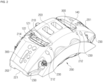
FIG. 2 is a perspective view of the brake dust collector in accordance with one embodiment of the present disclosure; -
FIG. 3 is a bottom perspective view illustrating the brake dust collector in accordance with one embodiment of the present disclosure; -
FIG. 4 is a sectional view illustrating a housing cross section of the brake dust collector in accordance with one embodiment of the present disclosure; -
FIG. 5 is a sectional view of the brake dust collector in accordance with one embodiment of the present disclosure; and -
FIGS. 6A and6B are sectional views illustrating a thickness of a conventional brake housing in which a filter module is omitted, and a thickness of a housing with a filter module in the brake dust collector in accordance with one embodiment of the present disclosure. - Hereinafter, embodiments of the present disclosure will be described in detail with reference to the accompanying drawings. The following embodiment is provided to fully convey the spirit of the present disclosure to a person having ordinary skill in the art to which the present disclosure belongs. The present disclosure is not limited to the embodiment shown herein but may be embodied in other forms. The drawings may omit the illustration of parts not related to the description in order to clarify the present invention, and slightly exaggerate the size of the components to help understanding.
-
FIG. 1 is an exploded perspective view of a brake dust collector in accordance with one embodiment of the present disclosure, andFIGS. 2 and3 are perspective views each illustrating a state where the brake dust collector in accordance with one embodiment of the present disclosure is coupled. In addition,FIG. 4 is a sectional view illustrating a housing cross section of the brake dust collector in accordance with one embodiment of the present disclosure, andFIG. 5 is a sectional view illustrating a cross section of the brake dust collector in accordance with one embodiment of the present disclosure. In addition,FIGS. 6A and6B are sectional views illustrating a thickness of a conventional brake housing in which a filter module is omitted, and a thickness of a housing with a filter module in the brake dust collector in accordance with one embodiment of the present disclosure. - Referring to
FIGS. 1 to 6 , a brake dust collector in accordance with one embodiment of the present disclosure includes apad module 100, ahousing 200 in which thepad module 100 is embedded, and afilter module 300 coupled to each of a leadingportion 201 and atrailing portion 202 of thehousing 200. - More specifically, the
pad module 100 includes a pair ofbrake pads 110 that are respectively disposed on both sides of a disc D rotating together with a wheel and are in close contact with or separated from the disc D according to a forward and backward movement of apiston 130, apad spring 120 provided between both ends of thebrake pads 110 and thehousing 200 to facilitate the forward and backward movement of thebrake pads 110, ashim pad 140 provided between thebrake pad 110 and thepiston 130 to prevent noise and vibration which occur during the forward and backward movement of thepiston 130, and aguide pin 150 configured to guide the forward and backward movement of thebrake pad 110. - The
brake pad 110 includes a backplate provided on a side of thepiston 130 and a friction layer provided to touch the disc D. Herein, the backplate and the friction layer may be integrally formed. In addition, thebrake pad 110 includes aguide hole 111 penetrated by theguide pin 150 on both sides of an upper portion. - The
pad spring 120, which is a leaf spring, includes a guidepin locking portion 121 provided in an upper center part and locked to a center part of theguide pin 150, ahousing locking portion 122 provided at an upper end and locked to thehousing 200, and apad support 123 provided at a lower end and configured to support a lower end of thebrake pad 110, and facilitates the forward and backward movement of thebrake pad 110 by preventing vibration during the forward and backward movement of thebrake pad 110. Herein, the guidepin locking portion 121, thehousing locking portion 122, and thepad support 123 may each be provided by bending a corresponding part of the leaf spring. - As described above, the
piston 130 is a device of advancing and retreating thebrake pad 110, and althoughFIG. 1 illustrates that thepiston 130 is coupled to thebrake pad 110, thepiston 130 may be installed into apiston insertion portion 211 in advance, which is provided at an inner side of thehousing 200, when thepad module 100 and thehousing 200 are coupled. In addition, various methods such as a hydraulic method, a mechanical method, and the like may be applied to thepiston 130. - The
shim pad 140 is a plate for preventing noise, vibration, and the like, which are caused by the forward and backward movement of thebrake pad 110, and is fastened to thebrake pad 110 to be provided between thebrake pad 110 and thepiston 130. To this end, theshim pad 140 includes at least one bent portion that can be fixed to thebrake pads 110 at an upper portion and a lower portion, respectively. Accordingly, when thepad module 100 is coupled to apad module seat 210, theshim pad 140 is located at the side of thepiston 130 which is inserted into thepiston insertion portion 211. - The
guide pin 150 includes a fixingmember fastening hole 152 provided at ahead 151 and a fixingmember 153 such as a fixing pin and the like, which is inserted into the fixingmember fastening hole 152 and prevents theguide pin 150 from being separated from thebrake pad 110 and thehousing 200. - Meanwhile, as illustrated in
FIG. 4 , thehousing 200 includes a plurality of heat dissipation holes 203 provided all over the surface, which includes the leadingportion 201 and the trailingportion 202, as a fluid flow passage, which exhausts heat caused by friction between thebrake pads 110 and the disc D to the outside of thehousing 200 and induces a fluid flow generated according to rotation of the disc D to thefilter module 300, and ahousing fastening portion 204 provided at one side of thehousing 200 to fasten thehousing 200 to a car body and the like. - Accordingly, the brake dust collector in accordance with the present embodiment may collect dust through a tangential air flow generated by rotation of a disc without a separate flow control element for dust induction.
- More specifically, the
housing 200 further includes thepad module seat 210 provided between the leadingportion 201 and the trailingportion 202 to enable thepad module 100 to be inserted into thehousing 200,filter module seats 220 formed to extend from both sides of an upper portion of thepad module seat 210 toward the leadingportion 201 and the trailingportion 202, and fastening member fastening holes 230 provided at both ends of each of the filter module seats 220. - In addition, the
housing 200 may be provided as a monoblock which is formed as an integral type to improve marketability through design. - The
pad module seat 210 includes apiston insertion portion 211 provided on thepad module seat 210 and in which thepiston 130 is inserted and installed, a guidepin fastening hole 212 provided so that theguide pin 150 may be penetrated and fastened from one side to the other side of thehousing 200, a padmodule exposure portion 213 formed to penetrate from an upper side to a lower side at both ends of thepad module seat 210; and apad spring support 214 provided at the padmodule exposure portion 213 to enable thehousing locking portion 122 to be supported. - Herein, the guide
pin fastening hole 212 may be formed in the padmodule exposure portion 213 to enable theguide pin 150, which penetrates the guidepin fastening hole 212 and theguide hole 111 through the padmodule exposure portion 213, to be identified at the upper side of thehousing 200. - The
filter module seat 220 has an overall arc shape and is formed to extend from one end of each of the leadingportion 201 and the trailingportion 202 to the padmodule exposure portion 213. In addition, as illustrated inFIG. 3 , thefilter module seat 220 includes anexposure groove 221 provided at one end of each of the leadingportion 201 and the trailingportion 202 to facilitate mounting of thepad module 100 and checking whether thepad module 100 is mounted. - The fastening
member fastening hole 230 is formed to penetrate from one side to the other side of thehousing 200 at both ends of thefilter module seat 220 so that thefilter module 300 is fixed to thefilter module seat 220. Herein, the fasteningmember fastening hole 230 may be provided as a hole to which processing such as tapping for fastening a bolt or the like, which may cause a decrease in stiffness of thehousing 200, is not applied. - Meanwhile, the
filter module 300 is a filter that collects dust generated by friction between the disc D and thebrake pad 110, and maintains its shape even against high-pressured washing liquid flowing through theheat dissipation hole 203 for cleaning, and may be provided using a metal material with excellent corrosion resistance and heat resistance. - Accordingly, the brake dust collector in accordance with the present embodiment may enable the
filter module 300 to be cleansed by washing liquid and the like even in a state in which thefilter module 300 is mounted on thehousing 200. - In addition, the
filter module 300 includes, when being coupled to thefilter module seat 220, a fastening member throughhole 310 provided at a position corresponding to the fasteningmember fastening hole 230, and afastening member 320 that fixes thefilter module 300 from thehousing 200. - Herein, the
fastening member 320 may be provided with a bolt penetrating the fasteningmember fastening hole 230 on one side and a nut fastened to the bolt exposed on the fasteningmember fastening hole 230 on the other side, and thus may serve as a fastening member of thehousing 200 and thefilter module 300 and a stiffness reinforcing member of thehousing 200, and various other means may be applied. - Accordingly, the brake dust collector in accordance with one embodiment of the present disclosure may minimize stiffness degradation of the
housing 200, which occurs since a thickness D2 of thehousing 200 due to thefilter module 300 as illustrated inFIG. 6B is thinner than a thickness D1 of theconventional housing 200 without the filter module as illustrated inFIG. 6A , by thefastening member 320. - In addition, when the
filter module 300 is inserted into thefilter module seat 230, an end of thepad module 100 is supported by thepad spring 120 so that excessive insertion may be prevented. - In addition, when the
filter module 300 is fixed to thefilter module seat 220 by thefastening member 320, for the smooth forward and backward movement of thebrake pads 110, thefilter module 300 may be provided to be spaced apart from thepad spring 120 at predetermined intervals. - Meanwhile, although not illustrated, a brake dust collector in accordance with another embodiment of the present disclosure may be provided with the
filter module 300 in only one of the leadingportion 201 or the trailingportion 202. Herein, since the typical air flow generated by the rotation of the disc D is induced from the leadingportion 201 to the trailingportion 202, thefilter module 300 may be more advantageously provided in the trailingportion 202 than in the leadingportion 201. - In addition, as described above, when the
filter module 300 is provided in the trailingportion 202, thefilter module seat 220, theexposure groove 221, and the fasteningmember fastening hole 230, which are intended to fasten thefilter module 300 to thehousing 200, may be provided on a side of the trailingportion 202, and may be omitted on a side of the leadingportion 201. - Accordingly, the brake dust collector in accordance with the present embodiment may further minimize stiffness degradation of the
housing 200 caused by thefilter module 300. - In addition, when the
filter module 300 is fixed to thefilter module seat 220 by thefastening member 320, for the smooth forward and backward movement of thebrake pads 110, thefilter module 300 may be provided to be spaced apart from thepad module 100 at predetermined intervals. - Accordingly, the brake dust collector in accordance with one embodiment of the present disclosure may add a dust collection function without significant change in design compared to a conventional monoblock caliper brake without a dust collection function, and thus may minimize stiffness degradation of the housing.
- A brake dust collector in accordance with the present embodiment can effectively collect dust generated by friction between a disc and a brake pad and discharged to the outside of a housing.
- A brake dust collector in accordance with the present embodiment can improve dust collection efficiency due to a filter module provided in each of a leading portion and a trailing portion.
- A brake dust collector in accordance with the present embodiment can facilitate management of a filter module by enabling the filter module to be cleansed by washing liquid and the like even in a state in which the filter module is mounted on a housing.
- A brake dust collector in accordance with the present embodiment can collect dust through a tangential air flow generated by rotation of a disc without a separate flow control element for dust induction.
- A brake dust collector in accordance with the present embodiment can omit a device for dust collection separately from a housing and thus prevent decline of aesthetics.
- A brake dust collector in accordance with the present embodiment can minimize stiffness degradation of a housing caused by a filter module inserted into the housing.
- Although a few embodiments of the present disclosure have been shown and described, it would be appreciated by those skilled in the art that changes may be made in these embodiments without departing from the principles and spirit of the disclosure, the scope of which is defined in the claims and their equivalents.
Claims (15)
- A brake dust collector comprising:a pad module including a pair of brake pads that are respectively disposed on both sides of a disc rotating together with a wheel and are in close contact with or separated from the disc according to a forward and backward movement of a piston;a housing provided to cover a part of the disc by forming a pad module seat provided between a leading portion and a trailing portion and to which the pad module is coupled, and filter module seats at inner sides of the leading portion and the trailing portion, respectively; anda filter module fixed to each of the filter module seats by a fastening member that penetrates and fastens from one side to the other side of the housing.
- The brake dust collector of claim 1, wherein the pad module further comprises:pad springs provided between both ends of the brake pad and the pad module seat;a shim pad provided between the brake pad and the piston; andguide pins provided in guide holes formed at both sides of an upper portion of the brake pad and configured to guide the forward and backward movement of the brake pad.
- The brake dust collector of claim 2, wherein each of the pad springs comprises:a guide pin locking portion provided in an upper center part and locked to a center part of the guide pin;a housing locking portion provided at an upper end and locked to the housing; andpad supports provided on both sides of a lower end of the brake pad and configured to support each side of the lower end of the brake pad.
- The brake dust collector of claim 3, wherein the housing further comprises:pad module exposure portions provided on both ends of the pad module seat to penetrate upwards, respectively; anda pad spring support provided at the pad module exposure portion and configured to seat the housing locking portion.
- The brake dust collector of claim 2, wherein the guide pin comprises:a fixing member fastening hole provided at a head side; anda fixing member inserted into the fixing member fastening hole to prevent the guide pin from being separated from the housing and the brake pad, andthe guide pin is coupled through a guide pin fastening hole provided in the pad module seat and the guide hole.
- The brake dust collector of claim 1, wherein the housing further comprises an exposure groove provided at an end of each of the leading portion and the trailing portion so that one end of the filter module is partially exposed.
- The brake dust collector according to any one of the preceding claims, wherein the filter module is fixed to the filter module seat with an end of the pad module being spaced at a predetermined interval from the pad spring.
- The brake dust collector according to any one of the preceding claims, wherein the filter module is fixed to the filter module seat with an end of the pad module being supported by the pad spring.
- The brake dust collector according to any one of the preceding claims, wherein the filter module comprises fastening member through holes, which are penetrated by the fastening members at both ends, and is fixed to the pad module seat by the fastening member fastening through a fastening member fastening hole provided in the pad module seat and the fastening member through hole.
- The brake dust collector according to any one of the preceding claims, wherein the housing is provided as a monoblock further including at least one or more heat dissipation holes that are provided as a heat exhaust passage and a fluid flow passage, respectively, in the leading portion and the trailing portion.
- A brake dust collector comprising:a pad module including a pair of brake pads that are respectively disposed on both sides of a disc rotating together with a wheel and are in close contact with or separated from the disc according to a forward and backward movement of a piston;a housing provided to cover a part of the disc by forming a pad module seat provided between a leading portion and a trailing portion and to which the pad module is coupled, and a filter module seat at an inner side of the trailing portion; anda filter module fixed to the filter module seat by a fastening member penetrating and fastening from one side to the other side of the housing through a fastening member fastening hole provided in the filter module seat.
- The brake dust collector of claim 11, wherein the housing further comprises an exposure groove provided at an end of the trailing portion so that one end of the filter module is partially exposed.
- The brake dust collector of any one of claims 11 to 12, wherein the housing is provided as a monoblock further including at least one or more heat dissipation holes that are provided as a heat exhaust passage and a fluid flow passage on the filter module seat.
- The brake dust collector of claim 11, wherein the fastening member is provided with:a bolt penetrating the fastening member fastening hole on one side; anda nut fastened to the bolt exposed to the fastening member fastening hole on the other side.
- The brake dust collector of any one of claims 11 to 13, wherein the filter module is fixed to the filter module seat at a predetermined interval from the pad module.
Applications Claiming Priority (1)
| Application Number | Priority Date | Filing Date | Title |
|---|---|---|---|
| KR1020230002907A KR20240111167A (en) | 2023-01-09 | 2023-01-09 | Brake dust collector |
Publications (2)
| Publication Number | Publication Date |
|---|---|
| EP4397879A1 true EP4397879A1 (en) | 2024-07-10 |
| EP4397879B1 EP4397879B1 (en) | 2024-12-11 |
Family
ID=87567368
Family Applications (1)
| Application Number | Title | Priority Date | Filing Date |
|---|---|---|---|
| EP23190525.8A Active EP4397879B1 (en) | 2023-01-09 | 2023-08-09 | Brake dust collector |
Country Status (3)
| Country | Link |
|---|---|
| US (1) | US20240229876A1 (en) |
| EP (1) | EP4397879B1 (en) |
| KR (1) | KR20240111167A (en) |
Citations (6)
| Publication number | Priority date | Publication date | Assignee | Title |
|---|---|---|---|---|
| US20100065387A1 (en) * | 2006-11-03 | 2010-03-18 | Konstantinos Tsiberidis | Brake dust collecting device |
| US20140054120A1 (en) * | 2012-08-27 | 2014-02-27 | Mann+Hummel Gmbh | Brake Dust Collector for Motor Vehicles |
| US20180031059A1 (en) * | 2016-07-29 | 2018-02-01 | Joseph Gelb | Brake Pad Waste Collector |
| DE102020111811A1 (en) * | 2020-04-30 | 2021-11-04 | Mann+Hummel Gmbh | Brake dust particle filter, disc brake assembly and use of a brake dust particle filter |
| DE102020126890A1 (en) * | 2020-10-13 | 2022-04-14 | Mann+Hummel Gmbh | Disc brake device, vehicle and brake pad |
| KR20220163108A (en) * | 2021-06-02 | 2022-12-09 | 현대모비스 주식회사 | Brake apparatus for vehicle |
Family Cites Families (4)
| Publication number | Priority date | Publication date | Assignee | Title |
|---|---|---|---|---|
| CA2645460C (en) | 2008-11-28 | 2015-12-29 | Ray Arbesman | Piston-side brake shim |
| KR102538298B1 (en) | 2020-12-29 | 2023-05-30 | 한국세라믹기술원 | Dust collecting apparatus for capturing dust generated in break apparatus of transportation means and manufacturing method of dust collecting apparatus |
| JP7542727B2 (en) | 2021-04-13 | 2024-08-30 | 日立Astemo株式会社 | Disc brake |
| DE102021114797B4 (en) | 2021-06-09 | 2024-11-07 | Mann+Hummel Gmbh | brake dust particle filter with a filter insert |
-
2023
- 2023-01-09 KR KR1020230002907A patent/KR20240111167A/en active Pending
- 2023-08-09 EP EP23190525.8A patent/EP4397879B1/en active Active
- 2023-08-22 US US18/236,594 patent/US20240229876A1/en active Pending
Patent Citations (6)
| Publication number | Priority date | Publication date | Assignee | Title |
|---|---|---|---|---|
| US20100065387A1 (en) * | 2006-11-03 | 2010-03-18 | Konstantinos Tsiberidis | Brake dust collecting device |
| US20140054120A1 (en) * | 2012-08-27 | 2014-02-27 | Mann+Hummel Gmbh | Brake Dust Collector for Motor Vehicles |
| US20180031059A1 (en) * | 2016-07-29 | 2018-02-01 | Joseph Gelb | Brake Pad Waste Collector |
| DE102020111811A1 (en) * | 2020-04-30 | 2021-11-04 | Mann+Hummel Gmbh | Brake dust particle filter, disc brake assembly and use of a brake dust particle filter |
| DE102020126890A1 (en) * | 2020-10-13 | 2022-04-14 | Mann+Hummel Gmbh | Disc brake device, vehicle and brake pad |
| KR20220163108A (en) * | 2021-06-02 | 2022-12-09 | 현대모비스 주식회사 | Brake apparatus for vehicle |
Also Published As
| Publication number | Publication date |
|---|---|
| EP4397879B1 (en) | 2024-12-11 |
| KR20240111167A (en) | 2024-07-16 |
| US20240229876A1 (en) | 2024-07-11 |
Similar Documents
| Publication | Publication Date | Title |
|---|---|---|
| CN100365312C (en) | Laminated shim for disc brake and pad unit having same | |
| CN103797265B (en) | Disc brakes and brake linings for motor vehicles | |
| US4180148A (en) | Anti-rattle spring member for a disc brake pad | |
| US20240229877A1 (en) | Brake dust collector | |
| JPH08200409A (en) | Disc brake | |
| JPH05193466A (en) | Spot type disc brake | |
| US20100051393A1 (en) | Brake pad clip with integrated pad return spring and wear indicator | |
| US20240229875A1 (en) | Brake dust collector | |
| CN101035997A (en) | Friction element and disc brake | |
| CN113124073B (en) | Pin boss metal piece for pad, pad for disc brake, and disc brake device | |
| KR20210143211A (en) | Braking system with centrifugal suction in the groove of the lining | |
| JP2004501321A (en) | Disc brakes for vehicles | |
| CN107061562A (en) | The brake lining and brake lining holding meanss of disk brake | |
| US20240229876A1 (en) | Brake dust collector | |
| JP3409130B2 (en) | Disc brake | |
| JPH05256331A (en) | Disc brake | |
| CN116215726A (en) | Brake pad for bicycle | |
| CN108431444A (en) | Pad assembly for caliper body | |
| EP1571074A1 (en) | Disk Brake | |
| US20240240680A1 (en) | Caliper brake | |
| US20160017943A1 (en) | Drum brake shoe | |
| US20250146547A1 (en) | Disc Brake for a Utility Vehicle, and Brake Lining for a Disc Brake | |
| JP2000145841A (en) | Disc brake | |
| JP2002250382A (en) | Disc brake cooling system | |
| KR20250028085A (en) | Brake dust collector |
Legal Events
| Date | Code | Title | Description |
|---|---|---|---|
| PUAI | Public reference made under article 153(3) epc to a published international application that has entered the european phase |
Free format text: ORIGINAL CODE: 0009012 |
|
| STAA | Information on the status of an ep patent application or granted ep patent |
Free format text: STATUS: REQUEST FOR EXAMINATION WAS MADE |
|
| 17P | Request for examination filed |
Effective date: 20230809 |
|
| AK | Designated contracting states |
Kind code of ref document: A1 Designated state(s): AL AT BE BG CH CY CZ DE DK EE ES FI FR GB GR HR HU IE IS IT LI LT LU LV MC ME MK MT NL NO PL PT RO RS SE SI SK SM TR |
|
| GRAP | Despatch of communication of intention to grant a patent |
Free format text: ORIGINAL CODE: EPIDOSNIGR1 |
|
| STAA | Information on the status of an ep patent application or granted ep patent |
Free format text: STATUS: GRANT OF PATENT IS INTENDED |
|
| INTG | Intention to grant announced |
Effective date: 20240923 |
|
| GRAS | Grant fee paid |
Free format text: ORIGINAL CODE: EPIDOSNIGR3 |
|
| GRAA | (expected) grant |
Free format text: ORIGINAL CODE: 0009210 |
|
| STAA | Information on the status of an ep patent application or granted ep patent |
Free format text: STATUS: THE PATENT HAS BEEN GRANTED |
|
| AK | Designated contracting states |
Kind code of ref document: B1 Designated state(s): AL AT BE BG CH CY CZ DE DK EE ES FI FR GB GR HR HU IE IS IT LI LT LU LV MC ME MK MT NL NO PL PT RO RS SE SI SK SM TR |
|
| REG | Reference to a national code |
Ref country code: GB Ref legal event code: FG4D |
|
| REG | Reference to a national code |
Ref country code: CH Ref legal event code: EP |
|
| REG | Reference to a national code |
Ref country code: IE Ref legal event code: FG4D |
|
| REG | Reference to a national code |
Ref country code: DE Ref legal event code: R096 Ref document number: 602023001325 Country of ref document: DE |
|
| REG | Reference to a national code |
Ref country code: LT Ref legal event code: MG9D |
|
| PG25 | Lapsed in a contracting state [announced via postgrant information from national office to epo] |
Ref country code: HR Free format text: LAPSE BECAUSE OF FAILURE TO SUBMIT A TRANSLATION OF THE DESCRIPTION OR TO PAY THE FEE WITHIN THE PRESCRIBED TIME-LIMIT Effective date: 20241211 |
|
| PG25 | Lapsed in a contracting state [announced via postgrant information from national office to epo] |
Ref country code: FI Free format text: LAPSE BECAUSE OF FAILURE TO SUBMIT A TRANSLATION OF THE DESCRIPTION OR TO PAY THE FEE WITHIN THE PRESCRIBED TIME-LIMIT Effective date: 20241211 |
|
| PG25 | Lapsed in a contracting state [announced via postgrant information from national office to epo] |
Ref country code: BG Free format text: LAPSE BECAUSE OF FAILURE TO SUBMIT A TRANSLATION OF THE DESCRIPTION OR TO PAY THE FEE WITHIN THE PRESCRIBED TIME-LIMIT Effective date: 20241211 |
|
| REG | Reference to a national code |
Ref country code: NL Ref legal event code: MP Effective date: 20241211 |
|
| PG25 | Lapsed in a contracting state [announced via postgrant information from national office to epo] |
Ref country code: ES Free format text: LAPSE BECAUSE OF FAILURE TO SUBMIT A TRANSLATION OF THE DESCRIPTION OR TO PAY THE FEE WITHIN THE PRESCRIBED TIME-LIMIT Effective date: 20241211 |
|
| PG25 | Lapsed in a contracting state [announced via postgrant information from national office to epo] |
Ref country code: NO Free format text: LAPSE BECAUSE OF FAILURE TO SUBMIT A TRANSLATION OF THE DESCRIPTION OR TO PAY THE FEE WITHIN THE PRESCRIBED TIME-LIMIT Effective date: 20250311 |
|
| PG25 | Lapsed in a contracting state [announced via postgrant information from national office to epo] |
Ref country code: LV Free format text: LAPSE BECAUSE OF FAILURE TO SUBMIT A TRANSLATION OF THE DESCRIPTION OR TO PAY THE FEE WITHIN THE PRESCRIBED TIME-LIMIT Effective date: 20241211 Ref country code: GR Free format text: LAPSE BECAUSE OF FAILURE TO SUBMIT A TRANSLATION OF THE DESCRIPTION OR TO PAY THE FEE WITHIN THE PRESCRIBED TIME-LIMIT Effective date: 20250312 |
|
| PG25 | Lapsed in a contracting state [announced via postgrant information from national office to epo] |
Ref country code: RS Free format text: LAPSE BECAUSE OF FAILURE TO SUBMIT A TRANSLATION OF THE DESCRIPTION OR TO PAY THE FEE WITHIN THE PRESCRIBED TIME-LIMIT Effective date: 20250311 |
|
| PG25 | Lapsed in a contracting state [announced via postgrant information from national office to epo] |
Ref country code: NL Free format text: LAPSE BECAUSE OF FAILURE TO SUBMIT A TRANSLATION OF THE DESCRIPTION OR TO PAY THE FEE WITHIN THE PRESCRIBED TIME-LIMIT Effective date: 20241211 |
|
| REG | Reference to a national code |
Ref country code: AT Ref legal event code: MK05 Ref document number: 1750579 Country of ref document: AT Kind code of ref document: T Effective date: 20241211 |
|
| PG25 | Lapsed in a contracting state [announced via postgrant information from national office to epo] |
Ref country code: SM Free format text: LAPSE BECAUSE OF FAILURE TO SUBMIT A TRANSLATION OF THE DESCRIPTION OR TO PAY THE FEE WITHIN THE PRESCRIBED TIME-LIMIT Effective date: 20241211 |
|
| PG25 | Lapsed in a contracting state [announced via postgrant information from national office to epo] |
Ref country code: PL Free format text: LAPSE BECAUSE OF FAILURE TO SUBMIT A TRANSLATION OF THE DESCRIPTION OR TO PAY THE FEE WITHIN THE PRESCRIBED TIME-LIMIT Effective date: 20241211 |
|
| PG25 | Lapsed in a contracting state [announced via postgrant information from national office to epo] |
Ref country code: IS Free format text: LAPSE BECAUSE OF FAILURE TO SUBMIT A TRANSLATION OF THE DESCRIPTION OR TO PAY THE FEE WITHIN THE PRESCRIBED TIME-LIMIT Effective date: 20250411 |
|
| PG25 | Lapsed in a contracting state [announced via postgrant information from national office to epo] |
Ref country code: PT Free format text: LAPSE BECAUSE OF FAILURE TO SUBMIT A TRANSLATION OF THE DESCRIPTION OR TO PAY THE FEE WITHIN THE PRESCRIBED TIME-LIMIT Effective date: 20250411 |
|
| PG25 | Lapsed in a contracting state [announced via postgrant information from national office to epo] |
Ref country code: EE Free format text: LAPSE BECAUSE OF FAILURE TO SUBMIT A TRANSLATION OF THE DESCRIPTION OR TO PAY THE FEE WITHIN THE PRESCRIBED TIME-LIMIT Effective date: 20241211 |
|
| PG25 | Lapsed in a contracting state [announced via postgrant information from national office to epo] |
Ref country code: AT Free format text: LAPSE BECAUSE OF FAILURE TO SUBMIT A TRANSLATION OF THE DESCRIPTION OR TO PAY THE FEE WITHIN THE PRESCRIBED TIME-LIMIT Effective date: 20241211 Ref country code: RO Free format text: LAPSE BECAUSE OF FAILURE TO SUBMIT A TRANSLATION OF THE DESCRIPTION OR TO PAY THE FEE WITHIN THE PRESCRIBED TIME-LIMIT Effective date: 20241211 |
|
| PG25 | Lapsed in a contracting state [announced via postgrant information from national office to epo] |
Ref country code: SK Free format text: LAPSE BECAUSE OF FAILURE TO SUBMIT A TRANSLATION OF THE DESCRIPTION OR TO PAY THE FEE WITHIN THE PRESCRIBED TIME-LIMIT Effective date: 20241211 |
|
| PG25 | Lapsed in a contracting state [announced via postgrant information from national office to epo] |
Ref country code: CZ Free format text: LAPSE BECAUSE OF FAILURE TO SUBMIT A TRANSLATION OF THE DESCRIPTION OR TO PAY THE FEE WITHIN THE PRESCRIBED TIME-LIMIT Effective date: 20241211 |
|
| PG25 | Lapsed in a contracting state [announced via postgrant information from national office to epo] |
Ref country code: IT Free format text: LAPSE BECAUSE OF FAILURE TO SUBMIT A TRANSLATION OF THE DESCRIPTION OR TO PAY THE FEE WITHIN THE PRESCRIBED TIME-LIMIT Effective date: 20241211 |
|
| PG25 | Lapsed in a contracting state [announced via postgrant information from national office to epo] |
Ref country code: SE Free format text: LAPSE BECAUSE OF FAILURE TO SUBMIT A TRANSLATION OF THE DESCRIPTION OR TO PAY THE FEE WITHIN THE PRESCRIBED TIME-LIMIT Effective date: 20241211 |
|
| REG | Reference to a national code |
Ref country code: DE Ref legal event code: R026 Ref document number: 602023001325 Country of ref document: DE |
|
| PLBI | Opposition filed |
Free format text: ORIGINAL CODE: 0009260 |
|
| PLAX | Notice of opposition and request to file observation + time limit sent |
Free format text: ORIGINAL CODE: EPIDOSNOBS2 |
|
| PG25 | Lapsed in a contracting state [announced via postgrant information from national office to epo] |
Ref country code: DK Free format text: LAPSE BECAUSE OF FAILURE TO SUBMIT A TRANSLATION OF THE DESCRIPTION OR TO PAY THE FEE WITHIN THE PRESCRIBED TIME-LIMIT Effective date: 20241211 |
|
| PGFP | Annual fee paid to national office [announced via postgrant information from national office to epo] |
Ref country code: DE Payment date: 20250609 Year of fee payment: 3 |
|
| 26 | Opposition filed |
Opponent name: VRI-PATENT MONITORING ASSOCIATION Effective date: 20250910 |
|
| PLBB | Reply of patent proprietor to notice(s) of opposition received |
Free format text: ORIGINAL CODE: EPIDOSNOBS3 |
|
| PLAB | Opposition data, opponent's data or that of the opponent's representative modified |
Free format text: ORIGINAL CODE: 0009299OPPO |
|
| PG25 | Lapsed in a contracting state [announced via postgrant information from national office to epo] |
Ref country code: MC Free format text: LAPSE BECAUSE OF FAILURE TO SUBMIT A TRANSLATION OF THE DESCRIPTION OR TO PAY THE FEE WITHIN THE PRESCRIBED TIME-LIMIT Effective date: 20241211 |
|
| REG | Reference to a national code |
Ref country code: CH Ref legal event code: L10 Free format text: ST27 STATUS EVENT CODE: U-0-0-L10-L00 (AS PROVIDED BY THE NATIONAL OFFICE) Effective date: 20260402 |
|
| PG25 | Lapsed in a contracting state [announced via postgrant information from national office to epo] |
Ref country code: LU Free format text: LAPSE BECAUSE OF NON-PAYMENT OF DUE FEES Effective date: 20250809 |
|
| R26 | Opposition filed (corrected) |
Opponent name: VRI-PATENT MONITORING ASSOCIATION Effective date: 20250910 |