EP4397868A1 - Riveted assembly, battery, electric device, and assembling method and apparatus for riveted assembly - Google Patents
Riveted assembly, battery, electric device, and assembling method and apparatus for riveted assembly Download PDFInfo
- Publication number
- EP4397868A1 EP4397868A1 EP22927923.7A EP22927923A EP4397868A1 EP 4397868 A1 EP4397868 A1 EP 4397868A1 EP 22927923 A EP22927923 A EP 22927923A EP 4397868 A1 EP4397868 A1 EP 4397868A1
- Authority
- EP
- European Patent Office
- Prior art keywords
- wall
- rivet body
- riveting
- weak
- limiting
- Prior art date
- Legal status (The legal status is an assumption and is not a legal conclusion. Google has not performed a legal analysis and makes no representation as to the accuracy of the status listed.)
- Pending
Links
Images


Classifications
-
- F—MECHANICAL ENGINEERING; LIGHTING; HEATING; WEAPONS; BLASTING
- F16—ENGINEERING ELEMENTS AND UNITS; GENERAL MEASURES FOR PRODUCING AND MAINTAINING EFFECTIVE FUNCTIONING OF MACHINES OR INSTALLATIONS; THERMAL INSULATION IN GENERAL
- F16B—DEVICES FOR FASTENING OR SECURING CONSTRUCTIONAL ELEMENTS OR MACHINE PARTS TOGETHER, e.g. NAILS, BOLTS, CIRCLIPS, CLAMPS, CLIPS OR WEDGES; JOINTS OR JOINTING
- F16B19/00—Bolts without screw-thread; Pins, including deformable elements; Rivets
- F16B19/04—Rivets; Spigots or the like fastened by riveting
- F16B19/08—Hollow rivets; Multi-part rivets
- F16B19/10—Hollow rivets; Multi-part rivets fastened by expanding mechanically
- F16B19/1027—Multi-part rivets
- F16B19/1036—Blind rivets
-
- B—PERFORMING OPERATIONS; TRANSPORTING
- B62—LAND VEHICLES FOR TRAVELLING OTHERWISE THAN ON RAILS
- B62D—MOTOR VEHICLES; TRAILERS
- B62D27/00—Connections between superstructure or understructure sub-units
- B62D27/02—Connections between superstructure or understructure sub-units rigid
- B62D27/023—Assembly of structural joints
-
- H—ELECTRICITY
- H01—ELECTRIC ELEMENTS
- H01M—PROCESSES OR MEANS, e.g. BATTERIES, FOR THE DIRECT CONVERSION OF CHEMICAL ENERGY INTO ELECTRICAL ENERGY
- H01M50/00—Constructional details or processes of manufacture of the non-active parts of electrochemical cells other than fuel cells, e.g. hybrid cells
- H01M50/20—Mountings; Secondary casings or frames; Racks, modules or packs; Suspension devices; Shock absorbers; Transport or carrying devices; Holders
- H01M50/262—Mountings; Secondary casings or frames; Racks, modules or packs; Suspension devices; Shock absorbers; Transport or carrying devices; Holders with fastening means, e.g. locks
-
- B—PERFORMING OPERATIONS; TRANSPORTING
- B60—VEHICLES IN GENERAL
- B60K—ARRANGEMENT OR MOUNTING OF PROPULSION UNITS OR OF TRANSMISSIONS IN VEHICLES; ARRANGEMENT OR MOUNTING OF PLURAL DIVERSE PRIME-MOVERS IN VEHICLES; AUXILIARY DRIVES FOR VEHICLES; INSTRUMENTATION OR DASHBOARDS FOR VEHICLES; ARRANGEMENTS IN CONNECTION WITH COOLING, AIR INTAKE, GAS EXHAUST OR FUEL SUPPLY OF PROPULSION UNITS IN VEHICLES
- B60K1/00—Arrangement or mounting of electrical propulsion units
- B60K1/04—Arrangement or mounting of electrical propulsion units of the electric storage means for propulsion
- B60K2001/0405—Arrangement or mounting of electrical propulsion units of the electric storage means for propulsion characterised by their position
- B60K2001/0438—Arrangement under the floor
-
- B—PERFORMING OPERATIONS; TRANSPORTING
- B62—LAND VEHICLES FOR TRAVELLING OTHERWISE THAN ON RAILS
- B62D—MOTOR VEHICLES; TRAILERS
- B62D25/00—Superstructure or monocoque structure sub-units; Parts or details thereof not otherwise provided for
- B62D25/20—Floors or bottom sub-units
-
- F—MECHANICAL ENGINEERING; LIGHTING; HEATING; WEAPONS; BLASTING
- F16—ENGINEERING ELEMENTS AND UNITS; GENERAL MEASURES FOR PRODUCING AND MAINTAINING EFFECTIVE FUNCTIONING OF MACHINES OR INSTALLATIONS; THERMAL INSULATION IN GENERAL
- F16B—DEVICES FOR FASTENING OR SECURING CONSTRUCTIONAL ELEMENTS OR MACHINE PARTS TOGETHER, e.g. NAILS, BOLTS, CIRCLIPS, CLAMPS, CLIPS OR WEDGES; JOINTS OR JOINTING
- F16B5/00—Joining sheets or plates, e.g. panels, to one another or to strips or bars parallel to them
- F16B5/04—Joining sheets or plates, e.g. panels, to one another or to strips or bars parallel to them by means of riveting
-
- H—ELECTRICITY
- H01—ELECTRIC ELEMENTS
- H01M—PROCESSES OR MEANS, e.g. BATTERIES, FOR THE DIRECT CONVERSION OF CHEMICAL ENERGY INTO ELECTRICAL ENERGY
- H01M2220/00—Batteries for particular applications
- H01M2220/20—Batteries in motive systems, e.g. vehicle, ship, plane
-
- H—ELECTRICITY
- H01—ELECTRIC ELEMENTS
- H01M—PROCESSES OR MEANS, e.g. BATTERIES, FOR THE DIRECT CONVERSION OF CHEMICAL ENERGY INTO ELECTRICAL ENERGY
- H01M50/00—Constructional details or processes of manufacture of the non-active parts of electrochemical cells other than fuel cells, e.g. hybrid cells
- H01M50/20—Mountings; Secondary casings or frames; Racks, modules or packs; Suspension devices; Shock absorbers; Transport or carrying devices; Holders
- H01M50/204—Racks, modules or packs for multiple batteries or multiple cells
- H01M50/207—Racks, modules or packs for multiple batteries or multiple cells characterised by their shape
- H01M50/213—Racks, modules or packs for multiple batteries or multiple cells characterised by their shape adapted for cells having curved cross-section, e.g. round or elliptic
-
- H—ELECTRICITY
- H01—ELECTRIC ELEMENTS
- H01M—PROCESSES OR MEANS, e.g. BATTERIES, FOR THE DIRECT CONVERSION OF CHEMICAL ENERGY INTO ELECTRICAL ENERGY
- H01M50/00—Constructional details or processes of manufacture of the non-active parts of electrochemical cells other than fuel cells, e.g. hybrid cells
- H01M50/20—Mountings; Secondary casings or frames; Racks, modules or packs; Suspension devices; Shock absorbers; Transport or carrying devices; Holders
- H01M50/249—Mountings; Secondary casings or frames; Racks, modules or packs; Suspension devices; Shock absorbers; Transport or carrying devices; Holders specially adapted for aircraft or vehicles, e.g. cars or trains
-
- Y—GENERAL TAGGING OF NEW TECHNOLOGICAL DEVELOPMENTS; GENERAL TAGGING OF CROSS-SECTIONAL TECHNOLOGIES SPANNING OVER SEVERAL SECTIONS OF THE IPC; TECHNICAL SUBJECTS COVERED BY FORMER USPC CROSS-REFERENCE ART COLLECTIONS [XRACs] AND DIGESTS
- Y02—TECHNOLOGIES OR APPLICATIONS FOR MITIGATION OR ADAPTATION AGAINST CLIMATE CHANGE
- Y02E—REDUCTION OF GREENHOUSE GAS [GHG] EMISSIONS, RELATED TO ENERGY GENERATION, TRANSMISSION OR DISTRIBUTION
- Y02E60/00—Enabling technologies; Technologies with a potential or indirect contribution to GHG emissions mitigation
- Y02E60/10—Energy storage using batteries
Definitions
- the battery generally includes a box body and a battery cell, and the battery cell is accommodated in the box body.
- a mounting bracket is disposed in the box body to limit the battery cell in the box body, so as to improve the stability of the battery cell in the box body.
- the connection stability between the mounting bracket and the box body is also one of the important factors affecting the stability of the battery cell in the box body. Therefore, how to improve the connection stability between the box body and the mounting bracket is an urgent problem to be solved in the field of battery technologies.
- an embodiment of the present application provides a riveting assembly, including a first member, a second member and a riveting piece; the first member has a first connecting portion; the second member has a first hollow portion, and the second member has a first wall and a second wall opposed to each other; the riveting piece includes a rivet body, the rivet body is configured to sequentially pass through the first wall, the first hollow portion, the second wall and the first connecting portion, and the first connecting portion is located on one side of the second wall facing away from the first wall; wherein in an axial direction of the rivet body, the rivet body has a first weak portion and a first limiting portion which are disposed at intervals, and the first weak portion is configured to protrude in a radial direction of the rivet body when the rivet body is stressed in the axial direction of the rivet body, so as to form a second limiting portion located in the first hollow portion, so that the first connecting portion and the second wall are connected between the first limiting portion and the second limiting portion.
- the riveting piece can stretch into the first hollow portion and limit and lock the second wall and the first connecting portion in the first hollow portion, thereby reducing a risk of relative shaking of the first member and the second member due to a gap between the second wall and the first connecting portion, and improving the connection stability between the first member and the second member. Moreover, the riveting piece can stretch into a relatively concealed space to realize locking, such as stretching into the first hollow portion, so that an application range of the riveting piece is wider.
- the stiffness of the first weak portion is smaller than the stiffness of the second weak portion, in a process of axially applying force to the rivet body, the first weak portion will deform prior to the second weak portion, and a distance between the first weak portion and the rivet body in a direction approaching from the first weak portion to the second weak portion remains unchanged during the force application process, which facilitates the deformation of the first weak portion of the rivet body into the second limiting portion by press riveting, thereby facilitating rivet of the first member and the second member through the riveting piece.
- the riveting portion is used to cooperate with the pull riveting tool that passes through the second hollow portion, so as to facilitate axially applying force on the rivet body. Moreover, the riveting tool penetrates into the second hollow portion to cooperate with the riveting portion, and no additional riveting space is required to be set.
- a stiffness of the third weak portion is greater than the stiffness of the second weak portion.
- a wall thickness of the third weak portion is greater than the wall thickness of the second weak portion, so that the stiffness of the third weak portion is greater than the stiffness of the second weak portion.
- the battery includes the battery box provided by the above embodiment, so that a connection relationship between a box body of the battery box and the mounting bracket is stable, thereby improving mounting stability of the battery cell in the battery box.
- the riveting piece can stretch into the first hollow portion and limit and lock the second wall and the first connecting portion in the first hollow portion, thereby reducing a risk of relative shaking of the first member and the second member due to a gap between the second wall and the first connecting portion, and improving the connection stability between the first member and the second member.
- the riveting piece can stretch into a relatively concealed space to realize locking, such as stretching into the first hollow portion, so that an application range of the riveting piece is wider.
- the assembling method of the riveting assembly further includes: performing pull riveting on the riveting piece, so that the second weak portion protrudes in the radial direction of the rivet body to form the first limiting portion.
- one end of the rivet body in a direction approaching from the first weak portion to the first limiting portion will move toward a direction close to the first connecting portion, by performing pull riveting on the riveting piece, it is possible to adapt to the movement of the end of the rivet body, thereby ensuring that the second weak portion deforms into the reliable first limiting portion.
- the riveting assembly further includes a third member.
- the assembling method of the riveting assembly further includes: providing the third member and positioning the third member on one side of the first wall facing away from the second wall.
- the riveting piece further includes a flange portion, the flange portion is connected to one end of the rivet body and located on one side of the third member facing away from the first wall, the rivet body further includes a third weak portion, the third weak portion is disposed close to the flange portion relative to the first weak portion.
- the third limiting portion fills the gap between the first wall and the third member or the third limiting portion and the flange portion jointly limit the first wall and the third member, both of which can reduce the risk of shaking of the first wall and the third member in the axial direction of the rivet body, thereby improving the mounting stability of the first wall and the third member.
- Icons 1000-Vehicle; 100-Battery; 10-Riveting assembly; 11-First member; 111-Accommodating space; 1111-Subspace; 1112-Opening; 112-First connecting portion; 113-First contour portion; 114-First bottom plate portion; 115-First reinforcing rib; 116-First supporting portion; 1161-First abutting portion; 12-Second member; 121-First hollow portion; 122-First wall; 123-Second wall; 124-First insertion hole; 13-Riveting piece; 131-Rivet body; 1311-First weak portion; 1312-Firstlimiting portion; 1312a-First limiting surface; 1312b-First guide surface; 1313-Second limiting portion; 1314-Second weak portion; 1315-Second hollow portion; 1316-Body portion; 13161-First groove; 13162-Second groove; 13163-Third groove; 1317-Riveting portion; 13
- the power battery is used in energy storage power source systems such as hydraulic, thermal, wind and solar power stations, in electric vehicles such as an electric bicycle, an electric motorcycle and an electric car, in military equipment and aerospace, and many other fields. With the continuous expansion of the application field of the power battery, the market quantity demand is also constantly expanding.
- Nut 15 has threaded hole 151, first protruding portion 152 and a deformation portion, nut 15 is provided with first protruding portion 152 at its opening end, and a diameter of first protruding portion 152 is greater than an outer diameter of nut 15.
- One end of nut 15 facing away from first protruding portion 152 passes through first connecting portion 112 of first member 11, and first protruding portion 152 is located on one side of first connecting portion 112 facing second wall 123.
- a deforming portion of nut 15 protrudes in a radial direction of nut 15 by pull riveting or press riveting to form second protruding portion 153, second protruding portion 153 is located on one side of first connecting portion 112 facing away from second wall 123, and first protruding portion 152 and second protruding portion 153 abut against two sides of first connecting portion 112 respectively, so that nut 15 is fixed to first connecting portion 112.
- Riveting piece 13 includes rivet body 131 and flange portion 132, and flange portion 132 is disposed at one axial end of rivet body 131. After nut 15 is fixed on first connecting portion 112, rivet body 131 sequentially passes through third member 14, first wall 122, first hollow portion 121, second wall 123 and first connecting portion 112, to make flange portion 132 be located on one side of third member 14 facing away from first wall 122. An end of rivet body 131 facing away from flange portion 132 is screwed into threaded hole 151 of nut 15. Therefore, nut 15, rivet body 131 and flange portion 132 together limit second member 12 between third member 14 and first connecting portion 112.
- riveting piece 13 can stretch into first hollow portion 121 and limit and lock second wall 123 and first connecting portion 112 in first hollow portion 121, thereby reducing a risk of relative shaking of first member 11 and second member 12 due to a gap between second wall 123 and first connecting portion 112, and improving the connection stability between first member 11 and second member 12. Moreover, riveting piece 13 can stretch into a relatively concealed space to realize locking, such as stretching into first hollow portion 121, so that an application range of riveting piece 13 is wider.
- Riveting assembly 10 disclosed in the embodiment of the present application may be used, but not limited to, in a battery, and electrical apparatus such as a vehicle, a ship, or an aircraft.
- the battery disclosed in the present application can be used to form a power supply system of the electrical equipment. In this way, it is beneficial to have a stable connection relationship between the box body of the battery box and the mounting bracket, thereby improving the mounting stability of the battery cell in the box body.
- Riveting assembly 10 described in the embodiment of the present application is suitable for battery 100, and electrical equipment using battery 100.
- a related structure of riveting assembly 10 is illustrated by taking riveting assembly 10 used in the battery box of battery 100 as an example.
- the electrical equipment may be a vehicle, a mobile phone, portable equipment, a laptop computer, a ship, a spacecraft, an electric toy, an electric tool, and the like.
- the vehicle may be a fuel vehicle, a gas vehicle or a new energy vehicle.
- the new energy vehicle may be an all-electric vehicle, a hybrid electric vehicle, an extended-range electric vehicle, or the like.
- the spacecraft includes an airplane, a rocket, a space shuttle, a spaceship, and the like.
- the electric toy includes a fixed or mobile electric toy, such as a game console, an electric car toy, an electric ship toy and an electric aircraft toy.
- the electric tool includes a metal cutting electric tool, a grinding electric tool, an assembly electric tool and a railway electric tool, such as an electric drill, an electric grinder, an electric wrench, an electric screwdriver, an electric hammer, an impact drill, a concrete vibrator and an electric planer.
- a metal cutting electric tool such as an electric drill, an electric grinder, an electric wrench, an electric screwdriver, an electric hammer, an impact drill, a concrete vibrator and an electric planer.
- vehicle 1000 For the convenience of illustration, the following embodiments take vehicle 1000 as an example to illustrate.
- first weak portion 1311 Since one end of rivet body 131 abuts against first abutting portion 1161, it is convenient to serve as a supporting point for press riveting. If the deformation of second weak portion 1314 is realized by press riveting, then along with the deformation of second weak portion 1314, first weak portion 1311 gradually moves towards the direction close to second wall 123, so that first weak portion 1311 is no longer located on one side of second wall 123 facing away from first connecting portion 112, and cannot play a limiting role on one side of second wall 123 facing away from first connecting portion 112 after deformation.
- first weak portion 1311 deforms into second limiting portion 1313 by press riveting, and then second weak portion deforms into first limiting portion 1312 by pull riveting.
- first weak portion 1311 and second weak portion 1314 may also be realized by pull riveting.
- the stiffness of second weak portion 1314 is smaller than the stiffness of third weak portion 1318, which facilitates the manufacture and molding of rivet body 131 of riveting piece 13.
- third groove 13163 may also be disposed on the outer surface of rivet body 131, or third grooves 13163 may be disposed on both the inner surface and the outer surface of rivet body 131, and third grooves 13163 on the inner surface and the outer surface of rivet body 131 are oppositely disposed.
- Second grooves 13162 may be a closed structure extending in the circumferential direction of rivet body 131
- third grooves 13163 may be a closed structure extending in the circumferential direction of rivet body 131.
- riveting assembly 10 is a battery box
- first member 11 is formed with accommodating space 111 for battery cell 20
- second member 12 is accommodated in accommodating space 111
- second member 12 is used to divide accommodating space 111 into subspace 1111 for accommodating battery cell 20.
- Riveting piece 13 of the battery box can stretch into first hollow portion 121 and limit and lock second wall 123 and first connecting portion 112 in first hollow portion 121, thereby reducing a risk of relative shaking of first member 11 and second member 12 due to gap 16 between second wall 123 and first connecting portion 112, improving the connection stability between the box body and the mounting bracket, and improving mounting stability of battery cell 20 mounted in subspace 1111.
- An embodiment of the present application further provides battery 100, including battery cell 20 and the battery box provided by the above embodiments.
- Battery cell 20 is accommodated in accommodating space 111 of first member 11 of the battery box, and is located in subspace 1111 defined by first member 11 and second member 12.
- Battery 100 includes the battery box provided by the above embodiment, so that the connection relationship between a box body of the battery box and a mounting bracket is stable, thereby improving mounting stability of battery cell 20 in the battery box.
- An embodiment of the present application provides electrical equipment, including battery 100 provided by the above embodiments.
- an embodiment of the present application provides an assembling method of riveting assembly 10, including:
- first member 11 has first connecting portion 112
- second member 12 has first hollow portion 121
- second member 12 has first wall 122 and second wall 123 opposed to each other, and first connecting portion 112 is located on one side of second wall 123 facing away from first wall 122
- riveting piece 13 includes rivet body 131, and in an axial direction of rivet body 131, rivet body 131 has first weak portion 1311 and first limiting portion 1312 which are disposed at intervals;
- step S200 when rivet body 131 sequentially passes through first wall 122, second wall 123, and first connecting portion 112, one end of riveting portion 1317 of rivet body 131 abuts against first abutting portion 1161 of first supporting portion 116, first weak portion 1311 is located on one side of second wall 123 facing away from first connecting portion 112, and first limiting portion 1312 is located on one side of first connecting portion 112 facing away from second wall 123. Taking an abutting position of rivet body 131 and first abutting portion 1161 as a supporting force point, first weak portion 1311 deforms into second limiting portion 1313 by performing press riveting on rivet body 131.
- a limiting space is formed between first limiting portion 1312 and second limiting portion 1313 to lock second wall 123 and first connecting portion 112 so as to realize the connection between first member 11 and second member 12. Therefore, this method makes riveting piece 13 be able to stretch into first hollow portion 121 and limit and lock second wall 123 and first connecting portion 112 in first hollow portion 121, thereby reducing a risk of relative shaking of first member 11 and second member 12 due to gap 16 between second wall 123 and first connecting portion 112, and improving the connection stability between first member 11 and second member 12. Moreover, riveting piece 13 can stretch into a relatively concealed space to realize locking, such as stretching into first hollow portion 121, so that an application range of riveting piece 13 is wider.
- rivet body 131 is further provided with second weak portion 1314.
- the assembling method of riveting assembly 10 further includes:
- step S200 after rivet body 131 sequentially passes through first wall 122, second wall 123, and first connecting portion 112, second weak portion 1314 is located on one side of first connecting portion 112 facing away from second wall 123.
- step S300 is executed, that is, after first weak portion 1311 deforms into second limiting portion 1313 by press riveting
- step S400 is executed, a pull riveting tool is inserted into second hollow portion 1315 of rivet body 131, and cooperates with riveting portion 1317, the pull riveting tool is used to perform pull riveting on rivet body 131, so that second weak portion 1314 deforms into first limiting portion 1312.
- riveting assembly 10 further includes third member 14.
- the assembling method of riveting assembly 10 further includes: S500, providing third member 14, and positioning third member 14 on one side of first wall 122 facing away from second wall 123.
- Riveting piece 13 further includes flange portion 132, flange portion 132 is connected to one end of rivet body 131 and is located on one side of third member 14 facing away from first wall 122, rivet body 131 further includes third weak portion 1318, and third weak portion 1318 is disposed closer to flange portion 132 relative to first weak portion 1311.
- the assembling method of riveting assembly 10 further includes: S600, performing press riveting on riveting piece 13, so that third weak portion 1318 protrudes in the radial direction of rivet body 131 to form third limiting portion 1319, and third limiting portion 1319 is configured to fill gap 16 between first wall 122 and third member 14, or third limiting portion 1319 is configured to cooperate with flange portion 132 to connect third member 14 and first wall 122 between flange portion 132 and third limiting portion 1319.
- step S500 one end of third member 14 is connected to second member 12, and a part of second member 12 extends to one side of first wall 122 facing away from second wall 123.
- step S200 rivet body 131 sequentially passes through third member 14, first wall 122, second wall 123 and first connecting portion 112, and flange portion 132 is located on one side of third member 14 facing away from first wall 122.
- Step S600 is executed after step S400, because first weak portion 1311 and second weak portion 1314 respectively deforms into second limiting portion 1313 and first limiting portion 1312, second limiting portion 1313 and second wall 123 abut against each other to be capable of serving as a supporting force point for deforming third weak portion 1318 by press riveting.
- Third limiting portion 1319 fills gap 16 between first wall 122 and third member 14 or third limiting portion 1319 and flange portion 132 jointly limit first wall 122 and third member 14, both of which can reduce the risk of shaking of first wall 122 and third member 14 in the axial direction of rivet body 131, thereby improving the mounting stability of first wall 122 and third member 14.
- an embodiment of the present application further provides assembling equipment 2000 of a riveting assembly.
- Assembling equipment 2000 of the riveting assembly includes a providing apparatus 2100 and an assembling apparatus 2200.
- the providing apparatus 2100 is configured to provide first member 11, second member 12 and riveting piece 13; first member 11 has first connecting portion 112; second member 12 has first hollow portion 121, second member 12 has first wall 122 and second wall 123 opposed to each other, and first connecting portion 112 is location on one side of second wall 123 facing away from first wall 122;
- riveting piece 13 includes rivet body 131, and in an axial direction of rivet body 131, rivet body 131 has first weak portion 1311 and first limiting portion 1312 which are disposed at intervals; and assembling apparatus 2200 is configured to sequentially pass rivet body 131 through first wall 122, first hollow portion 121, second wall 123 and first connecting portion 112, and apply force in an axial direction of rivet body 131, so that first weak portion 1311 protrudes in a radial direction of rivet
- Riveting assembly 10 includes first member 11, second member 12, riveting piece 13 and third member 14.
- First member 11 has first connecting portion 112.
- Second member 12 has first hollow portion 121
- second member 12 has first wall 122 and second wall 123 opposed to each other
- first connecting portion 112 is located on one side of second wall 123 facing away from first wall 122
- third member 14 and first member 11 extend to one side of first wall 122 facing away from second wall 123.
- Riveting piece 13 includes rivet body 131 and flange portion 132.
- Rivet body 131 includes body portion 1316 and riveting portion 1317.
- Riveting portion 1317 is connected to one end of body portion 1316
- flange portion 132 is connected to one end of body portion 1316 facing away from riveting portion 1317.
- Body portion 1316 of rivet body 131 is sequentially provided with third weak portion 1318, first weak portion 1311 and second weak portion 1314 in a direction approaching from flange portion 132 to riveting portion 1317.
- a stiffness of third weak portion 1318 is greater than a stiffness of second weak portion 1314.
- the stiffness of second weak portion 1314 is greater than a stiffness of first weak portion 1311.
- Rivet body 131 sequentially passes through third member 14, first wall 122, first hollow portion 121, second wall 123 and first connecting portion 112, so that first weak portion 1311 is located in first hollow portion 121 and located on one side of second wall 123 facing away from first connecting portion 112, and second weak portion 1314 is located on one side of first connecting portion 112 facing away from second wall 123.
- Press riveting is performed on riveting piece 13 first, so that first weak portion 1311 protrudes in a radial direction of rivet body 131 to deform into second limiting portion 1313, and then a pull riveting tool is inserted into second hollow portion 1315 of rivet body 131, and is in threaded fit with riveting portion 1317.
- Pull riveting is performed on riveting piece 13 through the pull riveting tool, so that second weak portion 1314 protrudes in the radial direction of rivet body 131 and deforms into first limiting portion 1312.
- First limiting portion 1312 and second limiting portion 1313 jointly limit and lock second wall 123 and first connecting portion, so as to realize the connection between first member 11 and second member 12.
- riveting piece 13 After performing press riveting on riveting piece 13 to make third weak portion 1318 protrude in the radial direction of rivet body 131 to deform into third limiting portion 1319, the third limiting portion 1319 fills gap 16 between first wall 122 and third member 14 or third limiting portion 1319 and flange portion 132 together limit first wall 122 and third member 14. Therefore, riveting piece 13 can connect first member 11, second member 12 and third member 14 into a whole, thereby reducing a risk of movement of second member 12 relative to the first member 11, and improving the connection stability between first member 11 and second member 12.
- riveting piece 13 can stretch into first hollow portion 121 and limit and lock second wall 123 and first connecting portion 112 in first hollow portion 121, thereby reducing a risk of relative shaking of first member 11 and second member 12 due to a gap between second wall 123 and first connecting portion 112, and improving the connection stability between first member 11 and second member 12. Moreover, riveting piece 13 can stretch into a relatively concealed space to realize locking, such as stretching into first hollow portion 121, so that an application range of riveting piece 13 is wider.
Landscapes
- Chemical & Material Sciences (AREA)
- Engineering & Computer Science (AREA)
- Chemical Kinetics & Catalysis (AREA)
- Electrochemistry (AREA)
- General Chemical & Material Sciences (AREA)
- Mechanical Engineering (AREA)
- General Engineering & Computer Science (AREA)
- Aviation & Aerospace Engineering (AREA)
- Combustion & Propulsion (AREA)
- Transportation (AREA)
- Insertion Pins And Rivets (AREA)
Abstract
Description
- The present application relates to the technical field of batteries, in particular to a riveting assembly, a battery, electrical equipment, and assembling method and equipment of the riveting assembly.
- At present, lithium-ion batteries are generally used in vehicles. As a rechargeable battery, the lithium-ion batteries have advantages of small size, high energy density, high power density, many cycle times and long storage time.
- The battery generally includes a box body and a battery cell, and the battery cell is accommodated in the box body. In order to improve stability of the battery cell in the box body, a mounting bracket is disposed in the box body to limit the battery cell in the box body, so as to improve the stability of the battery cell in the box body. The connection stability between the mounting bracket and the box body is also one of the important factors affecting the stability of the battery cell in the box body. Therefore, how to improve the connection stability between the box body and the mounting bracket is an urgent problem to be solved in the field of battery technologies.
- An embodiment of the present application provides a riveting assembly, a battery box, a battery, electrical equipment, and an assembly method and equipment of the riveting assembly, so as to improve connection stability between a box body and a mounting bracket.
- In the first aspect, an embodiment of the present application provides a riveting assembly, including a first member, a second member and a riveting piece; the first member has a first connecting portion; the second member has a first hollow portion, and the second member has a first wall and a second wall opposed to each other; the riveting piece includes a rivet body, the rivet body is configured to sequentially pass through the first wall, the first hollow portion, the second wall and the first connecting portion, and the first connecting portion is located on one side of the second wall facing away from the first wall; wherein in an axial direction of the rivet body, the rivet body has a first weak portion and a first limiting portion which are disposed at intervals, and the first weak portion is configured to protrude in a radial direction of the rivet body when the rivet body is stressed in the axial direction of the rivet body, so as to form a second limiting portion located in the first hollow portion, so that the first connecting portion and the second wall are connected between the first limiting portion and the second limiting portion.
- In the above technical solution, the rivet body of the riveting piece can sequentially pass through the first wall, the first hollow portion, the second wall and the first connecting portion, so that the first weak portion is located in the first hollow portion, and the first limiting portion is located on one side of the first connecting portion facing away from the second wall. By axially applying force to the rivet body, the first weak portion protrudes in the radial direction of the rivet body to form the second limiting portion, a limiting space is formed between the first limiting portion and the second limiting portion, so as to lock the second wall and the first connecting portion, thereby realizing the connection between the first member and the second member. Therefore, the riveting piece can stretch into the first hollow portion and limit and lock the second wall and the first connecting portion in the first hollow portion, thereby reducing a risk of relative shaking of the first member and the second member due to a gap between the second wall and the first connecting portion, and improving the connection stability between the first member and the second member. Moreover, the riveting piece can stretch into a relatively concealed space to realize locking, such as stretching into the first hollow portion, so that an application range of the riveting piece is wider.
- In some embodiments of the first aspect of the present application, the rivet body is further provided with a second weak portion, and the second weak portion is configured to protrude in the radial direction of the rivet body when the rivet body is stressed in the axial direction of the rivet body, so as to form the first limiting portion.
- In the above technical solution, the first limiting portion is formed by protruding and deforming of the second weak portion in the radial direction of the rivet body after the rivet body is axially stressed. Before the second weak portion deforms, the second weak portion has a small size in the radial direction of the rivet body, which facilitates the rivet body to pass through the first wall, the first hollow portion, the second wall and the first connecting portion, and facilitates the formation of the first limiting portion on one side of the first connecting portion facing away from the second wall so as to play a limiting role on the first connecting portion.
- In some embodiments of the first aspect of the present application, a stiffness of the first weak portion is smaller than a stiffness of the second weak portion.
- In the above technical solution, the stiffness of the first weak portion is smaller than the stiffness of the second weak portion, in a process of axially applying force to the rivet body, the first weak portion will deform prior to the second weak portion, and a distance between the first weak portion and the rivet body in a direction approaching from the first weak portion to the second weak portion remains unchanged during the force application process, which facilitates the deformation of the first weak portion of the rivet body into the second limiting portion by press riveting, thereby facilitating rivet of the first member and the second member through the riveting piece.
- In some embodiments of the first aspect of the present application, a wall thickness of the first weak portion is smaller than a wall thickness of the second weak portion, so that the stiffness of the first weak portion is smaller than the stiffness of the second weak portion.
- In the above technical solution, by setting the wall thickness of the first weak portion to be smaller than the wall thickness of the second weak portion, the stiffness of the first weak portion is smaller than the stiffness of the second weak portion, which facilitates the manufacture and molding of the rivet body of the riveting piece.
- In some embodiments of the first aspect of the present application, the rivet body includes a body portion and a riveting portion, the first weak portion and the first limiting portion are both disposed on the body portion, and the riveting portion is connected to the body portion and located on one side of the first limiting portion facing away from the first weak portion; and the rivet body has a second hollow portion, and the riveting portion is used to cooperate with a pull riveting tool that passes through the second hollow portion.
- In the above technical solution, the riveting portion is used to cooperate with the pull riveting tool that passes through the second hollow portion, so as to facilitate axially applying force on the rivet body. Moreover, the riveting tool penetrates into the second hollow portion to cooperate with the riveting portion, and no additional riveting space is required to be set.
- In some embodiments of the first aspect of the present application, the riveting portion is provided with an internal thread for connecting with the pull riveting tool.
- In the above technical solution, the internal thread of the riveting portion is in threaded fit with an external thread of the pull riveting tool, so that the connection between the riveting portion and the pull riveting tool is more convenient.
- In some embodiments of the first aspect of the present application, the riveting assembly further includes a third member, and the third member is located on one side of the first wall facing away from the second wall; and the riveting piece further includes a flange portion, and the flange portion is connected to one end of the rivet body and is located on one side of the third member facing away from the first wall.
- In the above technical solution, the third member is located on one side of the first wall facing away from the second wall, and the third member can play a limiting role on the second member on one side of the first wall facing away from the second wall; and the flange portion of the riveting piece is located on one side of the third member facing away from the first wall, the flange portion can play a limiting role on the third member, and the cooperation between the flange portion and the first limiting portion can limit the second member between the third member and the first connecting portion of the first member, thereby improving the connection stability between the first member and the second member.
- In some embodiments of the first aspect of the present application, the rivet body further includes a third weak portion, the thir weak portion is configured to protrude in the radial direction of the rivet body when the rivet body is stressed in the axial direction, so as to form a third limiting portion, and the third limiting portion is configured to fill a gap between the first wall and the third member.
- In the above technical solution, the third weak portion deforms to form a third limiting portion, and the third limiting portion fills the gap between the first wall and the third member, so that the possibility of movement of the third member and the first wall in the axial direction of the rivet body is small, and the stability of the connection among the first member, the second member and the third member is improved.
- In some embodiments of the first aspect of the present application, the rivet body further has a third weak portion, and the third weak portion is configured to protrude in the radial direction of the rivet body when the rivet body is stressed in the axial direction, so as to form the third limiting portion, so that the third member and the first wall are connected between the flange portion and the third limiting portion.
- In the above technical solution, the third weak portion deforms to form the third limiting portion, and the first wall and the third member are limited between the first limiting portion and the flange portion, which is conducive to maintaining a fixed relative position relationship between the first wall and the third member, thereby improving the connection stability of the first wall and the third member.
- In some embodiments of the first aspect of the present application, a stiffness of the third weak portion is greater than the stiffness of the second weak portion.
- In the above technical solution, the stiffness of the second weak portion is smaller than the stiffness of the third weak portion, in a process of axially applying force to the rivet body, the second weak portion will deform prior to the third weak portion, so that the second limiting portion formed by deforming of the first weak portion is limited on one side of the second wall facing away from the first connecting portion, and the second limiting portion can abut against one side of the second wall facing away from the first connecting portion, and can provide support for press riveting of the riveting piece, thereby facilitating the press riveting of the riveting piece to make the third weak portion deform into the third limiting portion.
- In some embodiments of the first aspect of the present application, a wall thickness of the third weak portion is greater than the wall thickness of the second weak portion, so that the stiffness of the third weak portion is greater than the stiffness of the second weak portion.
- In the above technical solution, by setting the wall thickness of the second weak portion to be smaller than the wall thickness of the third weak portion, the stiffness of the second weak portion is smaller than the stiffness of the third weak portion, which facilitates the manufacture and molding of the rivet body of the riveting piece.
- In some embodiments of the first aspect of the present application, the rivet body has a second hollow portion, an inner surface of the rivet body is provided with a first groove, and the rivet body forms the first weak portion in an area of the first groove.
- In the above technical solution, the inner surface of the rivet body is provided with the first groove, so that the wall thickness of the area of the first groove is smaller than a wall thickness of other non-weak portions of the rivet body, so that the area of the first groove correspondingly forms the first weak portion, and a forming mode of the first weak portion is simple, thereby reducing the manufacturing difficulty of the riveting piece.
- In some embodiments of the first aspect of the present application, the first groove is a closed structure extending in a circumferential direction of the rivet body.
- In the above technical solution, the first groove is the closed structure extending in the circumferential direction of the rivet body, then the first weak portion can protrude along the periphery and form the closed second limiting portion extending in the circumferential direction of the rivet body, which can better play a limiting role on the second wall.
- In some embodiments of the first aspect of the present application, the riveting assembly is a battery box, the first member is formed with an accommodating space for a battery cell, the second member is accommodated in the accommodating space, and the second member is used to divide the accommodating space into a subspace accommodating the battery cell.
- In the above technical solution, the first member is the box body of the battery box, the second memberis the mounting bracket of the battery box, the riveting piece of the battery box can stretch into the first hollow portion and limit and lock the second wall and the first connecting portion in the first hollow portion, thereby reducing the risk of relative shaking of the first member and the second member due to the gap between the second wall and the first connecting portion, namely, improving the connection stability between the box body and the mounting bracket, thereby improving the mounting stability of the battery cell mounted in the subspace.
- In a third aspect, an embodiment of the present application provide a battery, including a battery cell and a battery box provided by the above embodiment.
- In the above technical solution, the battery includes the battery box provided by the above embodiment, so that a connection relationship between a box body of the battery box and the mounting bracket is stable, thereby improving mounting stability of the battery cell in the battery box.
- In a third aspect, an embodiment of the present application provides electrical equipment, including the battery provided by the embodiment of the third aspect.
- In a fourth aspect, an embodiment of the present application provides an assembling method of a riveting assembly, including:
- providing a first member, a second member and a riveting piece, wherein the first member has a first connecting portion; the second member has a first hollow portion, the second member has a first wall and a second wall opposed to each other, and the first connecting portion is located on one side of the second wall facing away from the first wall; and the riveting piece includes a rivet body, and in an axial direction of the rivet body, the rivet body has a first weak portion and a first limiting portion which are disposed at intervals;
- passing the rivet body sequentially through the first wall, the first hollow portion, the second wall and the first connecting portion; and
- performing press riveting on the riveting piece, so that the first weak portion protrudes in a radial direction of the rivet body to form a second limiting portion, and thus the first connecting portion and the second wall are connected between the first limiting portion and the second limiting portion.
- In the above technical solution, the rivet body of the riveting piece sequentially passes through the first wall, the first hollow portion, the second wall and the first connecting portion, so that the first weak portion is located in the first hollow portion, and the first limiting portion is located on one side of the first connecting portion facing away from the second wall. By performing press riveting on the rivet body, the first weak portion protrudes in the radial direction of the rivet body to form the second limiting portion, a limiting space is formed between the first limiting portion and the second limiting portion, so as to lock the second wall and the first connecting portion, thereby realizing the connection between the first member and the second member. Therefore, through the method, the riveting piece can stretch into the first hollow portion and limit and lock the second wall and the first connecting portion in the first hollow portion, thereby reducing a risk of relative shaking of the first member and the second member due to a gap between the second wall and the first connecting portion, and improving the connection stability between the first member and the second member. Moreover, the riveting piece can stretch into a relatively concealed space to realize locking, such as stretching into the first hollow portion, so that an application range of the riveting piece is wider.
- In some embodiments of the fifth aspect of the present application, the rivet body is further provided with a second weak portion.
- The assembling method of the riveting assembly further includes:
performing pull riveting on the riveting piece, so that the second weak portion protrudes in the radial direction of the rivet body to form the first limiting portion. - In the above technical solution, in a process that the second weak portion deforms to form the first limiting portion, one end of the rivet body in a direction approaching from the first weak portion to the first limiting portion will move toward a direction close to the first connecting portion, by performing pull riveting on the riveting piece, it is possible to adapt to the movement of the end of the rivet body, thereby ensuring that the second weak portion deforms into the reliable first limiting portion.
- In some embodiments of the fifth aspect of the present application, the riveting assembly further includes a third member.
- The assembling method of the riveting assembly further includes:
providing the third member and positioning the third member on one side of the first wall facing away from the second wall. - The riveting piece further includes a flange portion, the flange portion is connected to one end of the rivet body and located on one side of the third member facing away from the first wall, the rivet body further includes a third weak portion, the third weak portion is disposed close to the flange portion relative to the first weak portion.
- The assembling method of the riveting assembly further includes:
performing press riveting on the riveting piece, so that the third weak portion protrudes in the radial direction of the rivet body to form a third limiting portion, wherein the third limiting portion is configured to fill a gap between the first wall and the third member, or the third limiting portion is configured to cooperate with the flange portion to connect the third member and the first wall between the flange portion and the third limiting portion. - In the above technical solution, by performing press riveting on the riveting piece, it is convenient for a riveting tool to apply an axial force to the riveting piece, thereby improving the assembling convenience and assembling efficiency. The third limiting portion fills the gap between the first wall and the third member or the third limiting portion and the flange portion jointly limit the first wall and the third member, both of which can reduce the risk of shaking of the first wall and the third member in the axial direction of the rivet body, thereby improving the mounting stability of the first wall and the third member.
- In a fifth aspect, an embodiment of the present application provides assembling equipment of a riveting assembly, including a providing apparatus and an assembling apparatus, wherein the providing apparatus is configured to provide a first member, a second member and a riveting piece; the first member has a first connecting portion; the second member has a first hollow portion, the second member has a first wall and a second wall opposed to each other, and the first connecting portion is located on one side of the second wall facing away from the first wall; the riveting piece includes a rivet body, and in an axial direction of the rivet body, the rivet body has a first weak portion and a first limiting portion which are disposed at intervals; the assembling apparatus is configured to sequentially pass the rivet body through the first wall, the first hollow portion, the second wall and the first connecting portion, and apply force in an axial direction of the rivet body, so that the first weak portion protrudes in a radial direction of the rivet body to form a first limiting portion, and the first connecting portion and the second wall are connected between the first limiting portion and the second limiting portion.
- To more clearly describe the technical solutions of the embodiments of the present application, the drawings to be used in the embodiments will be briefly introduced below, and it should be understood that the following drawings only show some embodiments of the present application, and therefore should not be considered as limiting the scope of the present application. For those of ordinary skills in the art, other relevant drawings may also be obtained based on these drawings without creative efforts.
-
Fig. 1 is a simplified structural view of an existing battery box; -
Fig. 2 is a schematic structural diagram of a vehicle provided by some embodiments of the present application; -
Fig. 3 is a schematic structural diagram of a battery provided by some embodiments of the present application; -
Fig. 4 is a schematic structural diagram of a riveting assembly provided by some embodiments of the present application; -
Fig. 5 is an enlarged view of a position I inFig. 4 ; -
Fig. 6 is a partial sectional view of a riveting assembly provided by some embodiments of the present application (a first weak portion, a second weak portion and a third weak portion do not deform along a radial convex portion of a rivet body); -
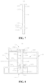
Fig. 7 is a schematic structural diagram of a riveting piece provided by some other embodiments of the present application; -
Fig. 8 is a sectional view of a riveting assembly provided by some embodiments of the present application (a first weak portion deforms into a second limiting portion); -
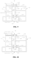
Fig. 9 is a sectional view of a riveting assembly provided by some embodiments of the present application (a first weak portion deforms into a second limiting portion, and a second weak portion deforms into a first limiting portion); -
Fig. 10 is a sectional view of a riveting assembly provided by some embodiments of the present application (a third limiting portion fills a gap between a first wall and a third member); -
Fig. 11 is a sectional view of a riveting assembly provided by some embodiments of the present application (there is no gap between a first wall and a third member, and a third weak portion does not deform into a third limiting portion); -
Fig. 12 is a sectional view of a riveting assembly provided by some embodiments of the present application (a third weak portion deforms into a third limiting portion and is located on one side of a first wall facing away from a third member); -
Fig. 13 is a schematic structural diagram of a riveting piece provided by some embodiments of the present application; -
Fig. 14 is a flowchart of an assembling method of a riveting assembly provided by some embodiments of the present application; and -
Fig. 15 is a schematic structural diagram of assembling equipment of a riveting assembly provided by some embodiments of the present application. - Icons: 1000-Vehicle; 100-Battery; 10-Riveting assembly; 11-First member; 111-Accommodating space; 1111-Subspace; 1112-Opening; 112-First connecting portion; 113-First contour portion; 114-First bottom plate portion; 115-First reinforcing rib; 116-First supporting portion; 1161-First abutting portion; 12-Second member; 121-First hollow portion; 122-First wall; 123-Second wall; 124-First insertion hole; 13-Riveting piece; 131-Rivet body; 1311-First weak portion; 1312-Firstlimiting portion; 1312a-First limiting surface; 1312b-First guide surface; 1313-Second limiting portion; 1314-Second weak portion; 1315-Second hollow portion; 1316-Body portion; 13161-First groove; 13162-Second groove; 13163-Third groove; 1317-Riveting portion; 1318-Third weak portion; 1319-Third limiting portion; 132-Flange portion; 14-Third member; 141-Second insertion hole; 15-Nut; 151-Threaded hole; 152-First protruding portion; 153-Second protruding portion; 16-Gap; 20-Battery cell; 30-Box cover; 200-Controller; 300-Motor; 2000-Assembling equipment of riveting assembly; 2100-Providing apparatus; 2200-Assembling apparatus.
- For the objects, technical solutions and advantages of the embodiments of the present application to be clearer, the technical solutions in the embodiments of the present application will be clearly and completely described below in conjunction with the drawings in the embodiments of the present application, and it is apparent that the described embodiments are a part of the embodiments of the present application rather than all the embodiments. The assembly of the embodiments of the present application generally described and illustrated in the drawings herein can be arranged and designed in a variety of different configurations.
- Accordingly, the following detailed description of the embodiments of the present application provided in the drawings is not intended to limit the scope of the claimed present application, but merely represents selected embodiments of the present application. Based on the embodiments in the present application, all other embodiments obtained by those of ordinary skill in the art without creative effort fall within the protection scope of the present application.
- It should be noted that in case of no conflicts, the embodiments in the present application and the features in the embodiments may be combined with each other.
- It should be noted that like numerals and letters denote similar items in the following drawings, therefore, once an item is defined in one drawing, it does not require further definition and explanation in subsequent drawings.
- In the description of the embodiments of the present application, it should be noted that the indication of orientation or positional relationship is orientation or positional relationship shown based on drawings, or is the orientation or positional relationship commonly placed during the use of the product of the present application, or is the orientation or positional relationship commonly understood by those skilled in the art. It is only for the convenience of describing the present application and simplifying the description, rather than indicating or implying that the apparatus or component referred to must have a specific orientation, or be constructed and operated in a specific orientation, therefore it cannot be understood as a limitation on the present application. In addition, terms "first", "second" and "third" are used to distinguish description only, and cannot be construed as indicating or implying relative importance.
- At present, from the perspective of the development of the market situation, a power battery is more and more widely used. The power battery is used in energy storage power source systems such as hydraulic, thermal, wind and solar power stations, in electric vehicles such as an electric bicycle, an electric motorcycle and an electric car, in military equipment and aerospace, and many other fields. With the continuous expansion of the application field of the power battery, the market quantity demand is also constantly expanding.
- As shown in
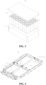
Fig. 1 , a battery box of an existing battery includesfirst member 11,second member 12 andthird member 14.First member 11 has first connectingportion 112, andfirst member 11 is formed withaccommodating space 111 for accommodatingbattery cell 20.Second member 12 is mounted inaccommodating space 111 and connected withfirst member 11, andsecond member 12 is used to divideaccommodating space 111 intosubspace 1111 for accommodatingbattery cell 20.First member 11 has first connectingportion 112,second member 12 has firsthollow portion 121 and is formed withfirst wall 122 andsecond wall 123 which are arranged oppositely, and first connectingportion 112 offirst member 11 is located on one side ofsecond wall 123 facing away fromfirst wall 122. Third member is connected withfirst member 11, and a part ofthird member 14 extends to one side offirst wall 122 facing away fromsecond wall 123. -
Battery 100 further includes a riveting member, and the riveting member is used for connectingfirst member 11,second member 12 andthird member 14 as a whole. The riveting member includesriveting piece 13 and nut 15. - Nut 15 has threaded
hole 151, first protrudingportion 152 and a deformation portion, nut 15 is provided with first protrudingportion 152 at its opening end, and a diameter of first protrudingportion 152 is greater than an outer diameter of nut 15. One end of nut 15 facing away from first protrudingportion 152 passes through first connectingportion 112 offirst member 11, and first protrudingportion 152 is located on one side of first connectingportion 112 facingsecond wall 123. A deforming portion of nut 15 protrudes in a radial direction of nut 15 by pull riveting or press riveting to form second protrudingportion 153, second protrudingportion 153 is located on one side of first connectingportion 112 facing away fromsecond wall 123, and first protrudingportion 152 and second protrudingportion 153 abut against two sides of first connectingportion 112 respectively, so that nut 15 is fixed to first connectingportion 112. -
Riveting piece 13 includesrivet body 131 andflange portion 132, andflange portion 132 is disposed at one axial end ofrivet body 131. After nut 15 is fixed on first connectingportion 112,rivet body 131 sequentially passes throughthird member 14,first wall 122, firsthollow portion 121,second wall 123 and first connectingportion 112, to makeflange portion 132 be located on one side ofthird member 14 facing away fromfirst wall 122. An end ofrivet body 131 facing away fromflange portion 132 is screwed into threadedhole 151 of nut 15. Therefore, nut 15,rivet body 131 andflange portion 132 together limitsecond member 12 betweenthird member 14 and first connectingportion 112. - An inventor found that since
second member 12 has firsthollow portion 121, nut 15 cannot form a limiting portion on one side ofsecond wall 123 facing away from first connectingportion 112, nor can it form limiting on one side offirst wall 122 facing away from a connecting piece, resulting in a risk of movement ofsecond member 12 betweenthird member 14 and first connectingportion 112. And after a long time of use, a screw connection relationship betweenrivet body 131 and nut 15 will fail, thus resulting in failure of a connection relationship betweenfirst member 11,second member 12 andthird member 14. - Based on the above considerations, in order to alleviate a problem that
second member 12 may move relative tofirst member 11, connection stability betweenfirst member 11 andsecond member 12 is improved. After in-depth research, the inventor relates toriveting assembly 10.Riveting assembly 10 includesfirst member 11 andsecond member 12, andfirst member 11 has first connectingportion 112;second member 12 has firsthollow portion 121, andsecond member 12 hasfirst wall 122 andsecond wall 123 opposed to each other; and rivetbody 131 ofriveting piece 13 is provided with first limitingportion 1312 and firstweak portion 1311 at intervals. -
Rivet body 131 ofriveting piece 13 sequentially passes throughfirst wall 122, firsthollow portion 121,second wall 123 and first connectingportion 112, so that firstweak portion 1311 is located in firsthollow portion 121, and first limitingportion 1312 is located on one side of first connectingportion 112 facing away fromsecond wall 123. By axially applying force to rivetbody 131, firstweak portion 1311 protrudes in the radial direction ofrivet body 131 to form second limitingportion 1313, a limiting space is formed between first limitingportion 1312 and second limitingportion 1313, so as to locksecond wall 123 and first connectingportion 112, thereby realizing the connection betweenfirst member 11 andsecond member 12. - Therefore,
riveting piece 13 can stretch into firsthollow portion 121 and limit and locksecond wall 123 and first connectingportion 112 in firsthollow portion 121, thereby reducing a risk of relative shaking offirst member 11 andsecond member 12 due to a gap betweensecond wall 123 and first connectingportion 112, and improving the connection stability betweenfirst member 11 andsecond member 12. Moreover,riveting piece 13 can stretch into a relatively concealed space to realize locking, such as stretching into firsthollow portion 121, so that an application range ofriveting piece 13 is wider. -
Riveting assembly 10 disclosed in the embodiment of the present application may be used, but not limited to, in a battery, and electrical apparatus such as a vehicle, a ship, or an aircraft. The battery disclosed in the present application can be used to form a power supply system of the electrical equipment. In this way, it is beneficial to have a stable connection relationship between the box body of the battery box and the mounting bracket, thereby improving the mounting stability of the battery cell in the box body. -
Riveting assembly 10 described in the embodiment of the present application is suitable forbattery 100, and electricalequipment using battery 100. Hereinafter, a related structure ofriveting assembly 10 is illustrated by takingriveting assembly 10 used in the battery box ofbattery 100 as an example. - The electrical equipment may be a vehicle, a mobile phone, portable equipment, a laptop computer, a ship, a spacecraft, an electric toy, an electric tool, and the like. The vehicle may be a fuel vehicle, a gas vehicle or a new energy vehicle. The new energy vehicle may be an all-electric vehicle, a hybrid electric vehicle, an extended-range electric vehicle, or the like. The spacecraft includes an airplane, a rocket, a space shuttle, a spaceship, and the like. The electric toy includes a fixed or mobile electric toy, such as a game console, an electric car toy, an electric ship toy and an electric aircraft toy. The electric tool includes a metal cutting electric tool, a grinding electric tool, an assembly electric tool and a railway electric tool, such as an electric drill, an electric grinder, an electric wrench, an electric screwdriver, an electric hammer, an impact drill, a concrete vibrator and an electric planer. The above electrical equipment is not specially limited in the embodiment of the present application.
- For the convenience of illustration, the following embodiments take
vehicle 1000 as an example to illustrate. - Please refer to
Fig. 2 ,vehicle 1000 is internally provided withbattery 100, andbattery 100 may be disposed at the bottom or head or tail ofvehicle 1000.Battery 100 may be used topower vehicle 1000. For example,battery 100 may be used as an operating power supply ofvehicle 1000. -
Vehicle 1000 may further includecontroller 200 andmotor 300, andcontroller 200 is used to controlbattery 100 topower motor 300, for example, used for meeting a working power demand during starting, navigating and traveling ofvehicle 1000. - In some embodiments of the present application,
battery 100 not only may serve as an operating power supply ofvehicle 1000, but also may serve as a driving power supply ofvehicle 1000, thus replacing or partially replacing fuel or natural gas to provide driving power forvehicle 1000. - Please refer to
Fig. 2 ,Fig. 3, and Fig. 4 . Thebattery 100 includes ariveting assembly 10 and abattery cell 20. Theriveting assembly 10 includes afirst member 11, asecond member 12, and ariveting member 13. Thefirst member 11 is formed to accommodate a battery cell. Theaccommodating space 111 of thebody 20.Second member 12 is accommodated inaccommodating space 111, andsecond member 12 is used to divideaccommodating space 111 into a plurality ofsubspaces 1111 for accommodatingbattery cells 20.Riveting piece 13 is used for rivetingfirst member 11 andsecond member 12 to form an integral structure. -
Accommodating space 111 hasopening 1112, and the battery box further includesbox cover 30 for coveringopening 1112 offirst member 11.Box cover 30 andfirst member 11 jointly define a closed space for accommodatingbattery cells 20 in the closed space. Of course, in order to improve the sealing performance of the battery box, a connected position betweenfirst member 11 and box cover 30 may be sealed by a sealing member (not shown in the figure), and the sealing member may be a sealing ring, a sealant, and the like. -
First member 11 and box cover 30 may be in various shapes, such as a cuboid and a cylinder.Box cover 30 may be a hollow structure with one side open to form an accommodating cavity for accommodatingbattery cell 20. The opening side of thebox cover 30 is disposed on an opening side offirst member 11. The accommodating cavity andaccommodating space 111 jointly define a closed space. Of course,box cover 30 may also be a plate structure, and box cover 30 covers the opening side offirst member 11 to form the box body with the closed space. - There may be one or
more battery cells 20 inbattery 100. If there are the plurality ofbattery cells 20, and the plurality ofbattery cells 20 may be in series connection or parallel connection or in parallel-series connection, wherein the parallel-series connection means that the plurality ofbattery cells 20 are connected in both series and parallel. The plurality ofbattery cells 20 may be directly connected in series, in parallel, or in a parallel-series connection together, and then a whole of the plurality ofbattery cells 20 is accommodated infirst member 11. Of course, it is also possible that the plurality ofbattery cells 20 are connected in series, in parallel, or in a parallel-series connection to form a battery module, and then the plurality of battery modules are connected in series, in parallel or in a parallel-series connection to form a whole, and accommodated infirst member 11.Battery cell 20 may be in a shape of a cylinder, a flat body, a cuboid or others.Fig. 3 exemplarily shows a case wherebattery cell 20 is a cylinder. - In some embodiments,
battery 100 may further include a busbar component (not shown in the figure), and the plurality ofbattery cells 20 may be electrically connected through the busbar component to achieve series, parallel, or parallel-series connection of the plurality ofbattery cells 20. - A structure of
battery cell 20 may refer to the related art, for example,battery cell 20 may include a case, an electrode assembly and an end cover assembly. The case has an opening, the electrode assembly is accommodated in the case, and the end cover assembly is used to cover the opening. - The case may be in various shapes, such as a cylinder and a cuboid. The shape of the case may be determined according to a specific shape of the electrode assembly. For example, if the electrode assembly is a cylindrical structure, the case may be selected as a cylindrical structure; and if the electrode assembly is a cuboid structure, the case may be selected as a cuboid structure.
- The case may also be made of various materials, such as copper, iron, aluminum, stainless steel and an aluminum alloy, which is not particularly limited in the embodiments of the present application.
- The electrode assembly may include a positive electrode plate (not shown in the figure), a negative electrode plate (not shown in the figure) and a separator (not shown in the figure). The electrode assembly may be a wound-type structure formed by winding the positive electrode plate, the separator and the negative electrode plate, or may be a stacked-type structure formed by stacking the positive electrode plate, the separator, and the negative electrode plate. The electrode assembly further include a positive tab (not shown in the figure) and a negative tab (not shown in the figure), It may be a positive electrode current collector not coated with a positive electrode active material layer in the positive electrode plate as the positive tab, or a negative electrode current collector not coated with a negative electrode active material layer in the negative electrode plate as the negative tab.
- The end cover assembly is used to cover the opening of the case to form a closed mounting space (not shown in the figure), and the mounting space is used to accommodate the electrode assembly. The mounting space is further used to accommodate electrolyte, such as an electrolytic solution. The end cover assembly serves as a part for outputting electrical energy of the electrode assembly. An electrode terminal in the end cover assembly is used to be electrically connected with the electrode assembly, that is, the electrode terminal is electrically connected with the tab of the electrode assembly. For example, the electrode terminal and the tab are connected through a current collecting member, so as to realize an electrical connection between the electrode terminal and the tab.
- As shown in
Fig. 4 ,Fig. 5 and Fig. 6 , In some embodiments,riveting assembly 10 includesfirst member 11,second member 12 andriveting piece 13;first member 11 has first connectingportion 112;second member 12 has girsthollow portion 121, andsecond member 12 hasfirst wall 122 andsecond wall 123 opposed to each other;riveting piece 13 includesrivet body 131,rivet body 131 is configured to sequentially pass throughfirst wall 122, firsthollow portion 121,second wall 123 and first connectingportion 112, and first connectingportion 112 is located on one side ofsecond wall 123 facing away fromfirst wall 122; wherein in an axial direction ofrivet body 131,rivet body 131 has firstweak portion 1311 and first limitingportion 1312 which are disposed at intervals, firstweak portion 1311 is configured to protrude in a radial direction ofrivet body 131 whenrivet body 131 is stressed in the axial direction ofrivet body 131, so as to form second limitingportion 1313 located in firsthollow portion 121, so that first connectingportion 112 andsecond wall 123 are connected between first limitingportion 1312 and second limitingportion 1313. -
First member 11 further hasfirst contour portion 113 and firstbottom plate portion 114,first contour portion 113 is disposed around firstbottom plate portion 114, andfirst contour portion 113 and firstbottom plate portion 114 jointly defineaccommodating space 111 offirst member 11.First member 11 is the box body.Second member 12 is the mounting bracket. -
First contour portion 113 is a hollow structure, which can reduce the weight offirst member 11. A plurality of first reinforcingribs 115 arranged at intervals are disposed infirst contour portion 113, which can enhance a strength and stiffness offirst contour portion 113 and improve a damage resistance and deformation resistance offirst contour portion 113. Certainly,first contour portion 113 may also be a solid structure. -
First member 11 further includes first supportingportion 116, and first supportingportion 116 is connected to an inner side offirst contour portion 113 and located inaccommodating space 111. First supportingportion 116 may be a hollow structure to reduce the weight offirst member 11. Certainly, first supportingportion 116 may also be a solid structure.Fig. 6 shows a case where first supportingportion 116 is a hollow structure. Wherein a wall of first supportingportion 116 facing opening 1112 of accommodatingspace 111 is first connectingportion 112. One end ofsecond member 12 is located on one side of first connectingportion 112 facing opening 1112 of accommodatingspace 111 and is supported by first connectingportion 112. First supportingportion 116 further has first abuttingportion 1161 disposed opposite to first connectingportion 112. -
Second member 12 has firsthollow portion 121, andfirst wall 122 andsecond wall 123 are respectively located on two opposite sides of firsthollow portion 121.First wall 122 is farther away from first connectingportion 112 thansecond wall 123, andsecond wall 123 and first connectingportion 112 are stacked and abut against each other. Under the action ofriveting piece 13,second wall 123 and first connectingportion 112 are limited and locked in a stacking direction.Second wall 123 and first connectingportion 112 are locked, which means thatriveting piece 13 keeps first connectingportion 112 andsecond wall 123 in a state of abutting against each other in the stacking direction. -
First wall 122,second wall 123 and first limitingportion 1312 are provided with first insertion holes 124 arranged coaxially.Rivet body 131 is configured to sequentially pass throughfirst wall 122, firsthollow portion 121,second wall 123 and first connectingportion 112, which means thatrivet body 131 is inserted from one side offirst wall 122 facing away fromsecond wall 123 and sequentially pass throughfirst insertion hole 124 offirst wall 122, firsthollow portion 121,first insertion hole 124 ofsecond wall 123 andfirst insertion hole 124 of first connectingportion 112. Afterrivet body 131 passes through first connectingportion 112, one end ofrivet body 131 is displaced into first supportingportion 116 and abuts against one side of first abuttingportion 1161 facing first connectingportion 112. - First limiting
portion 1312 is located on one side of first connectingportion 112 facing away fromsecond wall 123, in other words, first limitingportion 1312 is located in first supportingportion 116. First limitingportion 1312 is limited on one side of first connectingportion 112 facing away fromsecond wall 123, so as to limit the separation and limitation ofrivet body 131 in a direction approaching fromsecond wall 123 tofirst wall 122. - First
weak portion 1311 is located on one side ofsecond wall 123 facing away from first connectingportion 112, in other words, firstweak portion 1311 is located in firsthollow portion 121. After axially applying force to rivetbody 131 in the axial direction ofrivet body 131, firstweak portion 1311 protrudes in the radial direction ofrivet body 131 to form second limitingportion 1313, and second limitingportion 1313 is limited on one side ofsecond wall 123 facing away from first connectingportion 112, so as to limitrivet body 131 from moving in a direction approaching fromfirst wall 122 tosecond wall 123. First limitingportion 1312 and second limitingportion 1313 jointly keep first connectingportion 112 andsecond wall 123 in a state of abutting against each other, so thatfirst member 11 andsecond member 12 are connected as a whole byriveting piece 13. - Applying force to rivet
body 131 to deform firstweak portion 1311 into second limitingportion 1313 may be realized by pull riveting or press riveting. Stiffness of firstweak portion 1311 is smaller than stiffness of other non-weak portions ofrivet body 131, so that firstweak portion 1311 is prone to being deformed whenrivet body 131 is subjected to an axial force. - Therefore,
riveting piece 13 ofriveting assembly 10 can stretch into firsthollow portion 121 and limit and locksecond wall 123 and first connectingportion 112 in firsthollow portion 121, thereby reducing a risk of relative shaking offirst member 11 andsecond member 12 due to a gap betweensecond wall 123 and first connectingportion 112, improving the connection stability betweenfirst member 11 andsecond member 12, and improving mounting stability of the box body and mounting bracket of the battery box. A size of firstweak portion 1311 in a radial direction ofrivet body 131 before deformation is smaller than a size after deformation, so thatrivet body 131 can stretch into a relatively concealed space to realize locking, such as stretching into firsthollow portion 121, so that an application range ofriveting piece 13 is wider. - There are many ways to form first limiting
portion 1312. For example, as shown inFig. 7 , first limitingportion 1312 is disposed on an outer peripheral surface ofrivet body 131 and protrudes from the outer peripheral surface ofrivet body 131 in the radial direction ofrivet body 131. First limitingportion 1312 is an elastic member. First limitingportion 1312 has first limiting surface 1312a and first guidingsurface 1312b, first limiting surface 1312a is located on one side of first limitingportion 1312 facing firstweak portion 1311, and first guidingsurface 1312b is located on one side of first limitingportion 1312 facing away from firstweak portion 1311. Before the deformation of first limitingportion 1312, first limiting surface 1312a is a plane parallel to the radial direction ofrivet body 131, and first guidingsurface 1312b is an inclined plane gradually approaching first limiting surface 1312a in a direction of approaching from a central axis ofrivet body 131 to the outer peripheral surface ofrivet body 131. In a process that rivetbody 131 is inserted into eachfirst insertion hole 124, a hole wall offirst insertion hole 124 extrudes first guidingsurface 1312b, so as to drive first limitingportion 1312 to deform relative to rivetbody 131, and an outer diameter of deformed first limitingportion 1312 is the same as a hole diameter offirst insertion hole 124, so that first limitingportion 1312 can pass through eachfirst insertion hole 124 smoothly. After first limitingportion 1312 is separated from the hole wall offirst insertion hole 124, first limitingportion 1312 returns to its original shape, so that first limiting surface 1312 a is parallel to the radial direction ofrivet body 131. - For another embodiment, as shown in
Fig. 6 ,Fig. 8 , andFig. 9 ,rivet body 131 is further provided with secondweak portion 1314, and secondweak portion 1314 is configured to protrude in the radial direction ofrivet body 131 whenrivet body 131 is stressed in the axial direction ofrivet body 131, so as to form first limitingportion 1312. - Axially applying force to rivet
body 131 to make secondweak portion 1314 protrude in the radial direction ofrivet body 131 to form first limitingportion 1312, may refer to apply axial force to rivetbody 131 by means of pull riveting or press riveting. Stiffness of secondweak portion 1314 is smaller than stiffness of other non-weak portions ofrivet body 131, so that secondweak portion 1314 is prone to being deformed whenrivet body 131 is subjected to the axial force. - Before deformation, the outer diameter of second
weak portion 1314 is relatively small, which can ensure thatrivet body 131 is inserted into eachfirst insertion hole 124 in the direction approaching fromfirst wall 122 tosecond wall 123, and is located in on one side of first connectingportion 112 facing away fromsecond wall 123, that is, ensure thatrivet body 131 sequentially passes throughfirst wall 122, the first hollow portion,second wall 123 and first connectingportion 112. After the secondweak portion 1314 is deformed to form the first limitingportion 1312, the outer diameter of the first limitingportion 1312 increases and is larger than the diameter of thefirst insertion hole 124 of the first connectingportion 112, so that the first limitingportion 1312 can function as a stop on the side of the first connectingportion 112 away from thesecond wall 123. - Since one end of
rivet body 131 abuts against first abuttingportion 1161, it is convenient to serve as a supporting point for press riveting. If the deformation of secondweak portion 1314 is realized by press riveting, then along with the deformation of secondweak portion 1314, firstweak portion 1311 gradually moves towards the direction close tosecond wall 123, so that firstweak portion 1311 is no longer located on one side ofsecond wall 123 facing away from first connectingportion 112, and cannot play a limiting role on one side ofsecond wall 123 facing away from first connectingportion 112 after deformation. - Based on this, in some embodiments, the stiffness of first
weak portion 1311 is smaller than the stiffness of secondweak portion 1314. - When
rivet body 131 and first abuttingportion 1161 abut against each other to serve as a supporting point, firstweak portion 1311 deforms into second limitingportion 1313 by press riveting, and then second weak portion deforms into first limitingportion 1312 by pull riveting. Of course, in other embodiments, the deformation of firstweak portion 1311 and secondweak portion 1314 may also be realized by pull riveting. - The stiffness of first
weak portion 1311 is smaller than the stiffness of secondweak portion 1314, in a process of axially applying force to rivetbody 131, firstweak portion 1311 will deform prior to secondweak portion 1314, and a distance between firstweak portion 1311 and rivetbody 131 in a direction approaching from firstweak portion 1311 to secondweak portion 1314 remains unchanged during the force application process, which facilitates the deformation of firstweak portion 1311 ofrivet body 131 into second limitingportion 1313 by press riveting, thereby facilitating rivet offirst member 11 andsecond member 12 throughriveting piece 13. - Multiple ways may be adopted to realize that the stiffness of first
weak portion 1311 is smaller than the stiffness of secondweak portion 1314. In some embodiments, a wall thickness of firstweak portion 1311 is smaller than a wall thickness of secondweak portion 1314, so that the stiffness of firstweak portion 1311 is smaller than the stiffness of secondweak portion 1314. - In this embodiment,
rivet body 131 has secondhollow portion 1315. In the axial direction ofrivet body 131, secondhollow portion 1315 penetrates through two axial ends ofrivet body 131, so that a riveting tool penetrates from secondhollow portion 1315 to axially apply force to rivetbody 131. - Both first
weak portion 1311 and secondweak portion 1314 are parts that forms the wall ofrivet body 131. The wall thickness of firstweak portion 1311 and the wall thickness of secondweak portion 1314 both refer to the sizes of firstweak portion 1311 and secondweak portion 1314 in the radial direction ofrivet body 131 before deformation. Both the wall thickness of firstweak portion 1311 and the wall thickness of secondweak portion 1314 are smaller than the wall thickness of other non-weak portions ofrivet body 131. - In some other embodiments, it is also possible to make the stiffness of the material used for first
weak portion 1311 and secondweak portion 1314 is smaller than the stiffness of the materials of other non-weak portions ofrivet body 131 by changing the materials of firstweak portion 1311 and secondweak portion 1314. Moreover, the stiffness of the material of firstweak portion 1311 is smaller than the stiffness of the material of secondweak portion 1314. - By setting the wall thickness of first
weak portion 1311 to be smaller than the wall thickness of secondweak portion 1314, the stiffness of firstweak portion 1311 is smaller than the stiffness of secondweak portion 1314, which facilitates the manufacture and molding ofrivet body 131 ofriveting piece 13. - In order to facilitate performing pull riveting on
rivet body 131, please continue to refer toFig. 8 andFig. 9 , In some embodiments,rivet body 131 includesbody portion 1316 andriveting portion 1317, firstweak portion 1311 and first limitingportion 1312 are both disposed onbody portion 1316, andriveting portion 1317 is connected tobody portion 1316 and is located on one side of first limitingportion 1312 facing away from firstweak portion 1311; and rivetbody 131 has secondhollow portion 1315, andriveting portion 1317 is used for cooperating with the pull riveting tool passing through secondhollow portion 1315. -
Riveting portion 1317 is located on one side of first limitingportion 1312 facing away from firstweak portion 1311, and one end ofriveting portion 1317 abuts against first abuttingportion 1161, so that secondweak portion 1314 ofrivet body 131 deforms through pull riveting. Secondhollow portion 1315 penetrates throughbody portion 1316 andriveting portion 1317, andriveting portion 1317 is used to cooperate with a pull riveting tool passing through secondhollow portion 1315, so as to axially apply the force to rivetbody 131. Moreover, the riveting tool penetrates into secondhollow portion 1315 to cooperate withriveting portion 1317, and no additional riveting space is required to be set. - There are many ways for
riveting portion 1317 to cooperate with the pull riveting tool. In some embodiments,riveting portion 1317 is provided with an internal thread (not shown in the figure) for being connected with the pull riveting tool (not shown in the figure). - The internal thread is disposed in second
hollow portion 1315 and located on an inner surface ofriveting portion 1317. The part where the pull riveting tool penetrates into secondhollow portion 1315 is provided with an external thread, and the external thread is in threaded fit with the internal thread ofriveting portion 1317 to realize the connection betweenriveting portion 1317 and the pull riveting tool. - In some other embodiments,
riveting portion 1317 and the pull riveting tool may also be matched in other ways. For example, the inner surface ofriveting portion 1317 is provided with a first snap-fit portion (not shown in the figure), and the pull riveting tool is provided with a second snap-fit portion (not shown in the figure) for being in snap fit with the first snap-fit portion. The first snap-fit portion may be a concave portion, and the second snap-fit portion may be a protrusion that can be snapped into the concave portion. - The internal thread of
riveting portion 1317 is in threaded fit with the external thread of the pull riveting tool, so that the connection betweenriveting portion 1317 and the pull riveting tool is more convenient. - Please continue to refer to
Fig. 8 andFig. 9 , In some embodiments,riveting assembly 10 further includesthird member 14, andthird member 14 is located on one side offirst wall 122 facing away fromsecond wall 123; andriveting portion 13 further includesflange portion 132, andflange portion 132 is connected to one end ofrivet body 131 and is located on one side ofthird member 14 facing away fromfirst wall 122. - One end of
third member 14 is fixed withfirst member 11, andthird member 14 extends to one side offirst wall 122 facing away fromsecond wall 123. A part wherethird member 14 extends to one side offirst wall 122 facing away fromsecond wall 123 is provided withsecond insertion hole 141, andsecond insertion hole 141 is coaxial withfirst insertion hole 124 onfirst wall 122.Rivet body 131 sequentially pass throughsecond insertion hole 141 ofthird member 14,first insertion hole 124 offirst wall 122,first insertion hole 124 ofsecond wall 123 and an insertion hole of first connectingportion 112.Flange portion 132 is connected to one end ofbody portion 1316 facing away fromriveting portion 1317, and is located on one side ofthird member 14 facing away fromfirst wall 122. The outer diameter offlange portion 132 is greater than the hole diameter ofsecond insertion hole 141, so thatflange portion 132 cannot pass throughsecond insertion hole 141. -
Third member 14 is located on one side offirst wall 122 facing away fromsecond wall 123, andthird member 14 can play a limiting role onsecond member 12 on one side offirst wall 122 facing away fromsecond wall 123.Flange portion 132 ofriveting piece 13 is located on one side ofthird member 14 facing away fromfirst wall 122, the outer diameter offlange portion 132 is greater than the outer diameter ofsecond insertion hole 141,flange portion 132 can play a limiting role onthird member 14, and the cooperation betweenflange portion 132 and first limitingportion 1312 can limitsecond member 12 betweenthird member 14 and first connectingportion 112 offirst member 11, and can improve the connection stability betweenfirst member 11 andsecond member 12. - In some cases, there is no abutment between
first wall 122 andthird member 14 in the axial direction ofrivet body 131 but there isgap 16, which leads to a risk of shaking betweensecond member 12 andthird member 14. - Based on this, please continue to refer to
Fig. 9 and Fig. 10 , In some embodiments,rivet body 131 further includes thirdweak portion 1318, the thirdweak portion 1318 is configured to protrude in the radial direction ofrivet body 131 whenrivet body 131 is stressed in the axial direction to form third limitingportion 1319, and third limitingportion 1319 is configured to fillgap 16 betweenfirst wall 122 andthird member 14. - Filling
gap 16 betweenfirst wall 122 andthird member 14 by third limitingportion 1319 may be completely filled, that is, the size of third limitingportion 1319 in the axial direction ofrivet body 131 is the same as the size ofgap 16 betweenfirst wall 122 andthird member 14 in the axial direction ofrivet body 131. Fillinggap 16 betweenfirst wall 122 andthird member 14 by third limitingportion 1319 may be partially filled, that is, the size of third limitingportion 1319 in the axial direction ofrivet body 131 is smaller than the size ofgap 16 betweenfirst wall 122 andthird member 14 in the axial direction ofrivet body 131. - Third
weak portion 1318 deforms to form third limitingportion 1319, and third limitingportion 1319 fillsgap 16 betweenfirst wall 122 andthird member 14, so that the possibility of movement ofthird member 14 andfirst wall 122 in the axial direction ofrivet body 131 is small, and the stability of the connection amongfirst member 11,second member 12 andthird member 14 is improved. - In some other embodiments, as shown in
Fig. 11 and Fig. 12 ,rivet body 131 further has thirdweak portion 1318, and thirdweak portion 1318 is configured to protrude in the radial direction ofrivet body 131 whenrivet body 131 is stressed in the axial direction, so as to form third limitingportion 1319, so thatthird member 14 andfirst wall 122 are connected betweenflange portion 132 and third limitingportion 1319. - The outer diameter of third limiting
portion 1319 is greater than the hole diameter offirst insertion hole 124 onfirst wall 122, and third limitingportion 1319 can limit first connectingportion 112 on one side offirst wall 122 facing away from it, and cooperate withflange portion 132 to form a limiting space forfirst wall 122 andthird member 14. Regardless of whether there isgap 16 betweenfirst wall 122 andthird member 14 in the axial direction ofrivet body 131, third limitingportion 1319 andflange portion 132 cooperate to jointly limitfirst wall 122 andthird member 14, which can reduce or avoided the risk of movement ofsecond member 12 relative tothird member 14, thereby improving connection stability betweenfirst wall 122 andthird member 14. Moreover,flange portion 132, the third limiting portion, first limitingportion 1312 and second limitingportion 1313 work together to improve the connection stability amongfirst member 11,second member 12 andthird member 14. - In some embodiments, the stiffness of third
weak portion 1318 is greater than the stiffness of secondweak portion 1314. - The stiffness of third
weak portion 1318 and secondweak portion 1314 refers to the ability of thirdweak portion 1318 and secondweak portion 1314 to resist deformation respectively. The greater the stiffness, the stronger the deformation resistance, and vice versa. The stiffness of thirdweak portion 1318 is greater than the stiffness of secondweak portion 1314, and the deformation resistance of thirdweak portion 1318 is stronger than that of secondweak portion 1314. A relationship of the stiffness among firstweak portion 1311, secondweak portion 1314 and thirdweak portion 1318 is: the stiffness of firstweak portion 1311 is smaller than the stiffness of secondweak portion 1314, and the stiffness of secondweak portion 1314 is smaller than the stiffness of thirdweak portion 1318. - In a process of axially applying force to rivet
body 131 and secondweak portion 1314 deforming into first limitingportion 1312, thirdweak portion 1318 may not be deformed, or may be deformed. In an embodiment where third limitingportion 1319 deformed from thirdweak portion 1318 fillsgap 16 betweenfirst wall 122 andthird member 14, in a process of deforming firstweak portion 1311 by press riveting, one end ofrivet body 131 provided withflange portion 132 moves in a direction of approaching fromfirst wall 122 tosecond wall 123, thirdweak portion 1318 also moves in the direction of approaching fromfirst wall 122 tosecond wall 123, thirdweak portion 1318 is not deformed, and then the third limiting portion can pass throughsecond insertion hole 141 smoothly and be located betweenthird member 14 andfirst wall 122. If thirdweak portion 1318 deforms in the deformation process of firstweak portion 1311, deformed third limitingportion 1319 cannot be located betweenthird member 14 andfirst wall 122 to fillgap 16 betweenthird member 14 andfirst wall 122. - In an embodiment in which
first wall 122 andthird member 14 are limited between third limitingportion 1319 andflange portion 132 by third limitingportion 1319 deformed from thirdweak portion 1318 andflange portion 132, in the process of deforming firstweak portion 1311 by press riveting, one end ofrivet body 131 provided withflange portion 132 moves in the direction of approaching fromfirst wall 122 tosecond wall 123. Although thirdweak portion 1318 also moves in the direction of approaching fromfirst wall 122 tosecond wall 123, only deformed third limitingportion 1319 is still located on one side ofthird member 14 facing away fromfirst wall 122, no matter whether thirdweak portion 1318 deforms in the wall deformation process of firstweak portion 1311, third limitingportion 1319 deformed from thirdweak portion 1318 andflange portion 132 can jointly limitfirst wall 122 andthird member 14. - The stiffness of second
weak portion 1314 is smaller than the stiffness of thirdweak portion 1318, in a process of axially applying force to rivetbody 131, secondweak portion 1314 will deform prior to thirdweak portion 1318, so that second limitingportion 1313 formed by deforming of firstweak portion 1311 is limited on one side ofsecond wall 123 facing away from first connectingportion 112, and second limitingportion 1313 can abut against one side ofsecond wall 123 facing away from first connectingportion 112, and can provide support for press riveting ofriveting piece 13, thereby facilitating the press riveting ofriveting piece 13 to make thirdweak portion 1318 deform into third limitingportion 1319. - Multiple ways may be adopted to realize that the stiffness of second
weak portion 1314 is smaller than the stiffness of thirdweak portion 1318. In some embodiments, the wall thickness of thirdweak portion 1318 is greater than the wall thickness of secondweak portion 1314, so that the stiffness of thirdweak portion 1318 is greater than the stiffness of secondweak portion 1314. - Third
weak portion 1318 is a part that forms the wall ofrivet body 131. The wall thickness of thirdweak portion 1318 refers to the size of thirdweak portion 1318 in the radial direction ofrivet body 131 before deformation. The wall thickness of thirdweak portion 1318 is smaller than the wall thickness of other non-weak portions ofrivet body 131. The wall thickness of thirdweak portion 1318 is greater than the wall thickness of firstweak portion 1311 and the wall thickness of secondweak portion 1314. - In some other embodiments, it is also possible to make the stiffness of the material used for third
weak portion 1318 is smaller than the stiffness of materials of other non-weak portions ofrivet body 131 by changing the materials of thirdweak portion 1318. Moreover, the stiffness of the material of thirdweak portion 1318 is greater than the stiffness of the material of secondweak portion 1314. - By setting the wall thickness of second
weak portion 1314 to be smaller than the wall thickness of thirdweak portion 1318, the stiffness of secondweak portion 1314 is smaller than the stiffness of thirdweak portion 1318, which facilitates the manufacture and molding ofrivet body 131 ofriveting piece 13. - Please continue to refer to
Fig. 13 , In some embodiments,rivet body 131 has secondhollow portion 1315, the inner surface of therivet body 131 is provided withfirst groove 13161, and rivetbody 131 forms firstweak portion 1311 in the area offirst groove 13161. -
First groove 13161 is disposed on the inner surface ofbody portion 1316 ofrivet body 131, andfirst groove 13161 is disposed, so that the wall thickness of the position corresponding tofirst groove 13161 is relatively small, and firstweak portion 1311 is formed infirst groove 13161, so that the wall thickness of firstweak portion 1311 is smaller than the wall thickness of other non-weak portions ofrivet body 131. Of course,first groove 13161 may also be disposed on the outer surface ofbody portion 1316, orfirst grooves 13161 may be disposed on both the inner surface and the outer surface ofbody portion 1316, andfirst grooves 13161 on the inner surface and the outer surface ofrivet body 131 are oppositely disposed. - The inner surface of
rivet body 131 is provided withfirst groove 13161, so that the wall thickness of the area offirst groove 13161 is smaller than the wall thickness of other non-weak portions ofrivet body 131, so that the area offirst groove 13161 correspondingly forms firstweak portion 1311, and a forming mode of firstweak portion 1311 is simple, thereby reducing the manufacturing difficulty ofriveting piece 13. - Please continue to refer to
Fig. 13 , In some embodiments,first groove 13161 is a closed structure extending in a circumferential direction ofrivet body 131. - The closed structure refers to
first grooves 13161 connected end-to-end in the circumferential direction ofrivet body 131. -
First groove 13161 is the closed structure extending in the circumferential direction ofrivet body 131, then firstweak portion 1311 can protrude along the periphery and form closed second limitingportion 1313 extending in the circumferential direction ofrivet body 131, which can better play a limiting role onsecond wall 123. - Please continue to refer to
Fig. 13 , the inner surface ofrivet body 131 is further provided with second groove 13162 andthird groove 13163.Rivet body 131 forms secondweak portion 1314 in the area of second groove 13162. Of course, second groove 13162 may also be disposed on the outer surface ofrivet body 131, or second grooves 13162 may be disposed on both the inner surface and the outer surface ofrivet body 131, and second grooves 13162 on the inner surface and the outer surface ofrivet body 131 are oppositely disposed.Rivet body 131 forms thirdweak portion 1318 in the area ofthird groove 13163. Of course,third groove 13163 may also be disposed on the outer surface ofrivet body 131, orthird grooves 13163 may be disposed on both the inner surface and the outer surface ofrivet body 131, andthird grooves 13163 on the inner surface and the outer surface ofrivet body 131 are oppositely disposed. - In order to make the stiffness of first
weak portion 1311 smaller than the stiffness of secondweak portion 1314, and the stiffness of secondweak portion 1314 smaller than the stiffness of thirdweak portion 1318, a sum of the depths offirst grooves 13161 is greater than a sum of depths of second grooves 13162, and the sum of the depths of second grooves 13162 is greater than the sum of depths ofthird grooves 13163. - Second grooves 13162 may be a closed structure extending in the circumferential direction of
rivet body 131, andthird grooves 13163 may be a closed structure extending in the circumferential direction ofrivet body 131. - In some embodiments,
riveting assembly 10 is a battery box,first member 11 is formed withaccommodating space 111 forbattery cell 20,second member 12 is accommodated inaccommodating space 111, andsecond member 12 is used to divideaccommodating space 111 intosubspace 1111 for accommodatingbattery cell 20. -
First member 11 is the box body of the battery box, andsecond member 12 is the mounting bracket of the battery box. -
Riveting piece 13 of the battery box can stretch into firsthollow portion 121 and limit and locksecond wall 123 and first connectingportion 112 in firsthollow portion 121, thereby reducing a risk of relative shaking offirst member 11 andsecond member 12 due togap 16 betweensecond wall 123 and first connectingportion 112, improving the connection stability between the box body and the mounting bracket, and improving mounting stability ofbattery cell 20 mounted insubspace 1111. - An embodiment of the present application further provides
battery 100, includingbattery cell 20 and the battery box provided by the above embodiments. - There may be one or
more battery cells 20, and "a plurality of" refers to two or more than two.Battery cell 20 is accommodated inaccommodating space 111 offirst member 11 of the battery box, and is located insubspace 1111 defined byfirst member 11 andsecond member 12. -
Battery 100 includes the battery box provided by the above embodiment, so that the connection relationship between a box body of the battery box and a mounting bracket is stable, thereby improving mounting stability ofbattery cell 20 in the battery box. - An embodiment of the present application provides electrical equipment, including
battery 100 provided by the above embodiments. - As shown in
Fig. 14 , an embodiment of the present application provides an assembling method ofriveting assembly 10, including: - S100, providing
first member 11,second member 12 andriveting piece 13, whereinfirst member 11 has first connectingportion 112;second member 12 has firsthollow portion 121,second member 12 hasfirst wall 122 andsecond wall 123 opposed to each other, and first connectingportion 112 is located on one side ofsecond wall 123 facing away fromfirst wall 122; andriveting piece 13 includesrivet body 131, and in an axial direction ofrivet body 131,rivet body 131 has firstweak portion 1311 and first limitingportion 1312 which are disposed at intervals; - S200, sequentially passing
rivet body 131 throughfirst wall 122, firsthollow portion 121,second wall 123 and first connectingportion 112; and - S300, performing press riveting on
riveting piece 13, so that firstweak portion 1311 protrudes in a radial direction ofrivet body 131 to form second limitingportion 1313, and first connectingportion 112 andsecond wall 123 are connected between first connectingportion 1312 and second limitingportion 1313. - In step S200, when
rivet body 131 sequentially passes throughfirst wall 122,second wall 123, and first connectingportion 112, one end ofriveting portion 1317 ofrivet body 131 abuts against first abuttingportion 1161 of first supportingportion 116, firstweak portion 1311 is located on one side ofsecond wall 123 facing away from first connectingportion 112, and first limitingportion 1312 is located on one side of first connectingportion 112 facing away fromsecond wall 123. Taking an abutting position ofrivet body 131 and first abuttingportion 1161 as a supporting force point, firstweak portion 1311 deforms into second limitingportion 1313 by performing press riveting onrivet body 131. - A limiting space is formed between first limiting
portion 1312 and second limitingportion 1313 to locksecond wall 123 and first connectingportion 112 so as to realize the connection betweenfirst member 11 andsecond member 12. Therefore, this method makesriveting piece 13 be able to stretch into firsthollow portion 121 and limit and locksecond wall 123 and first connectingportion 112 in firsthollow portion 121, thereby reducing a risk of relative shaking offirst member 11 andsecond member 12 due togap 16 betweensecond wall 123 and first connectingportion 112, and improving the connection stability betweenfirst member 11 andsecond member 12. Moreover,riveting piece 13 can stretch into a relatively concealed space to realize locking, such as stretching into firsthollow portion 121, so that an application range ofriveting piece 13 is wider. - Please continue to refer to
Fig. 14 , In some embodiments,rivet body 131 is further provided with secondweak portion 1314. - The assembling method of
riveting assembly 10 further includes: - S400, performing pull riveting on
riveting piece 13, so that secondweak portion 1314 protrudes in a radial direction ofrivet body 131 to form first limitingportion 1312. - In step S200, after
rivet body 131 sequentially passes throughfirst wall 122,second wall 123, and first connectingportion 112, secondweak portion 1314 is located on one side of first connectingportion 112 facing away fromsecond wall 123. After step S300 is executed, that is, after firstweak portion 1311 deforms into second limitingportion 1313 by press riveting, step S400 is executed, a pull riveting tool is inserted into secondhollow portion 1315 ofrivet body 131, and cooperates withriveting portion 1317, the pull riveting tool is used to perform pull riveting onrivet body 131, so that secondweak portion 1314 deforms into first limitingportion 1312. - In a process that second
weak portion 1314 deforms to form first limitingportion 1312, one end ofrivet body 131 in a direction approaching from firstweak portion 1311 to first limitingportion 1312 will move toward a direction close to first connectingportion 112, by performing pull riveting onriveting piece 13, it is possible to adapt to the movement of the end ofrivet body 131, thereby ensuring that secondweak portion 1314 deforms into reliable first limitingportion 1312. - Please continue to refer to
Fig. 14 , In some embodiments,riveting assembly 10 further includesthird member 14. - The assembling method of
riveting assembly 10 further includes:
S500, providingthird member 14, and positioningthird member 14 on one side offirst wall 122 facing away fromsecond wall 123. -
Riveting piece 13 further includesflange portion 132,flange portion 132 is connected to one end ofrivet body 131 and is located on one side ofthird member 14 facing away fromfirst wall 122,rivet body 131 further includes thirdweak portion 1318, and thirdweak portion 1318 is disposed closer toflange portion 132 relative to firstweak portion 1311. - The assembling method of
riveting assembly 10 further includes:
S600, performing press riveting onriveting piece 13, so that thirdweak portion 1318 protrudes in the radial direction ofrivet body 131 to form third limitingportion 1319, and third limitingportion 1319 is configured to fillgap 16 betweenfirst wall 122 andthird member 14, or third limitingportion 1319 is configured to cooperate withflange portion 132 to connectthird member 14 andfirst wall 122 betweenflange portion 132 and third limitingportion 1319. - In step S500, one end of
third member 14 is connected tosecond member 12, and a part ofsecond member 12 extends to one side offirst wall 122 facing away fromsecond wall 123. - In step S200,
rivet body 131 sequentially passes throughthird member 14,first wall 122,second wall 123 and first connectingportion 112, andflange portion 132 is located on one side ofthird member 14 facing away fromfirst wall 122. Step S600 is executed after step S400, because firstweak portion 1311 and secondweak portion 1314 respectively deforms into second limitingportion 1313 and first limitingportion 1312, second limitingportion 1313 andsecond wall 123 abut against each other to be capable of serving as a supporting force point for deforming thirdweak portion 1318 by press riveting. - By performing press riveting on
riveting piece 13, it is convenient for a riveting tool to apply an axial force toriveting piece 13, thereby improving the assembling convenience and assembling efficiency. Third limitingportion 1319 fillsgap 16 betweenfirst wall 122 andthird member 14 or third limitingportion 1319 andflange portion 132 jointly limitfirst wall 122 andthird member 14, both of which can reduce the risk of shaking offirst wall 122 andthird member 14 in the axial direction ofrivet body 131, thereby improving the mounting stability offirst wall 122 andthird member 14. - As shown in
Fig. 15 , an embodiment of the present application further providesassembling equipment 2000 of a riveting assembly.Assembling equipment 2000 of the riveting assembly includes a providingapparatus 2100 and anassembling apparatus 2200. The providingapparatus 2100 is configured to providefirst member 11,second member 12 andriveting piece 13;first member 11 has first connectingportion 112;second member 12 has firsthollow portion 121,second member 12 hasfirst wall 122 andsecond wall 123 opposed to each other, and first connectingportion 112 is location on one side ofsecond wall 123 facing away fromfirst wall 122;riveting piece 13 includesrivet body 131, and in an axial direction ofrivet body 131,rivet body 131 has firstweak portion 1311 and first limitingportion 1312 which are disposed at intervals; and assemblingapparatus 2200 is configured to sequentiallypass rivet body 131 throughfirst wall 122, firsthollow portion 121,second wall 123 and first connectingportion 112, and apply force in an axial direction ofrivet body 131, so that firstweak portion 1311 protrudes in a radial direction ofrivet body 131 to form first limitingportion 1312, and first connectingportion 112 andsecond wall 123 are connected between first limitingportion 1312 and second limitingportion 1313. - An embodiment of the present application provides
riveting assembly 10.Riveting assembly 10 includesfirst member 11,second member 12,riveting piece 13 andthird member 14. -
First member 11 has first connectingportion 112.Second member 12 has firsthollow portion 121,second member 12 hasfirst wall 122 andsecond wall 123 opposed to each other, first connectingportion 112 is located on one side ofsecond wall 123 facing away fromfirst wall 122, andthird member 14 andfirst member 11 extend to one side offirst wall 122 facing away fromsecond wall 123.Riveting piece 13 includesrivet body 131 andflange portion 132.Rivet body 131 includesbody portion 1316 andriveting portion 1317.Riveting portion 1317 is connected to one end ofbody portion 1316, andflange portion 132 is connected to one end ofbody portion 1316 facing away fromriveting portion 1317.Body portion 1316 ofrivet body 131 is sequentially provided with thirdweak portion 1318, firstweak portion 1311 and secondweak portion 1314 in a direction approaching fromflange portion 132 toriveting portion 1317. A stiffness of thirdweak portion 1318 is greater than a stiffness of secondweak portion 1314. The stiffness of secondweak portion 1314 is greater than a stiffness of firstweak portion 1311.Rivet body 131 sequentially passes throughthird member 14,first wall 122, firsthollow portion 121,second wall 123 and first connectingportion 112, so that firstweak portion 1311 is located in firsthollow portion 121 and located on one side ofsecond wall 123 facing away from first connectingportion 112, and secondweak portion 1314 is located on one side of first connectingportion 112 facing away fromsecond wall 123. Press riveting is performed onriveting piece 13 first, so that firstweak portion 1311 protrudes in a radial direction ofrivet body 131 to deform into second limitingportion 1313, and then a pull riveting tool is inserted into secondhollow portion 1315 ofrivet body 131, and is in threaded fit withriveting portion 1317. Pull riveting is performed onriveting piece 13 through the pull riveting tool, so that secondweak portion 1314 protrudes in the radial direction ofrivet body 131 and deforms into first limitingportion 1312. First limitingportion 1312 and second limitingportion 1313 jointly limit and locksecond wall 123 and first connecting portion, so as to realize the connection betweenfirst member 11 andsecond member 12. After performing press riveting onriveting piece 13 to make thirdweak portion 1318 protrude in the radial direction ofrivet body 131 to deform into third limitingportion 1319, the third limitingportion 1319 fillsgap 16 betweenfirst wall 122 andthird member 14 or third limitingportion 1319 andflange portion 132 together limitfirst wall 122 andthird member 14. Therefore,riveting piece 13 can connectfirst member 11,second member 12 andthird member 14 into a whole, thereby reducing a risk of movement ofsecond member 12 relative to thefirst member 11, and improving the connection stability betweenfirst member 11 andsecond member 12. Therefore,riveting piece 13 can stretch into firsthollow portion 121 and limit and locksecond wall 123 and first connectingportion 112 in firsthollow portion 121, thereby reducing a risk of relative shaking offirst member 11 andsecond member 12 due to a gap betweensecond wall 123 and first connectingportion 112, and improving the connection stability betweenfirst member 11 andsecond member 12. Moreover,riveting piece 13 can stretch into a relatively concealed space to realize locking, such as stretching into firsthollow portion 121, so that an application range ofriveting piece 13 is wider. - The above are only preferred embodiments of the present application, and are not intended to limit the present application. For those skilled in the art, the present application may have various modifications and changes. Any modifications, equivalent replacements, improvements, etc. made within the spirit and principle of the present application shall be included within the scope of protection of the present application.
Claims (20)
- A riveting assembly, comprising:a first member, having a first connecting portion;a second member, having a first hollow portion, and having a first wall and a second wall opposed to each other; anda riveting piece, comprising a rivet body configured to sequentially pass through the first wall, the first hollow portion, the second wall and the first connecting portion, the first connecting portion being located on one side of the second wall facing away from the first wall;wherein in an axial direction of the rivet body, the rivet body has a first weak portion and a first limiting portion which are disposed at intervals, and the first weak portion is configured to protrude in a radial direction of the rivet body when the rivet body is stressed in the axial direction of the rivet body, so as to form a second limiting portion located in the first hollow portion, so that the first connecting portion and the second wall are connected between the first limiting portion and the second limiting portion.
- The riveting assembly according to claim 1, wherein the rivet body is further provided with a second weak portion, and the second weak portion is configured to protrude in the radial direction of the rivet body when the rivet body is stressed in the axial direction of the rivet body, so as to form the first limiting portion.
- The riveting assembly according to claim 2, wherein a stiffness of the first weak portion is smaller than a stiffness of the second weak portion.
- The riveting assembly according to claim 3, wherein a wall thickness of the first weak portion is smaller than a wall thickness of the second weak portion, so that the stiffness of the first weak portion is smaller than the stiffness of the second weak portion.
- The riveting assembly according to any one of claims 1-4, wherein the rivet body comprises a body portion and a riveting portion, the first weak portion and the first limiting portion are both disposed on the body portion, and the riveting portion is connected to the body portion and located on one side of the first limiting portion facing away from the first weak portion; and
the rivet body has a second hollow portion, and the riveting portion is used to cooperate with a pull riveting tool passing through the second hollow portion. - The riveting assembly according to claim 5, wherein the riveting portion is provided with an internal thread for being connected with the pull riveting tool.
- The riveting assembly according to any one of claims 2-6, further comprising a third member, wherein the third member is located on one side of the first wall facing away from the second wall; and
the riveting piece further comprises a flange portion, and the flange portion is connected to one end of the rivet body and located on one side of the third member facing away from the first wall. - The riveting assembly according to claim 7, wherein the rivet body further comprises a third weak portion, the third weak portion is configured to protrude in the radial direction of the rivet body when the rivet body is stressed in the axial direction, so as to form a third limiting portion, and the third limiting portion is configured to fill a gap between the first wall and the third member.
- The riveting assembly according to claim 7, wherein the rivet body further has a third weak portion, and the third weak portion is configured to protrude in the radial direction of the rivet body when the rivet body is stressed in the axial direction, so as to form a third limiting portion, so that the third member and the first wall are connected between the flange portion and the third limiting portion.
- The riveting assembly according to any one of claims 8-9, wherein a stiffness of the third weak portion is greater than the stiffness of the second weak portion.
- The riveting assembly according to claim 10, wherein a wall thickness of the third weak portion is greater than the wall thickness of the second weak portion, so that the stiffness of the third weak portion is greater than the stiffness of the second weak portion.
- The riveting assembly according to any one of claims 1-11, wherein the rivet body has a second hollow portion, an inner surface of the rivet body is provided with a first groove, and the rivet body forms the first weak portion in an area of the first groove.
- The riveting assembly according to claim 12, wherein the first groove is a closed structure extending in a circumferential direction of the rivet body.
- The riveting assembly according to any one of claims 1-13, wherein the riveting assembly is a battery box, the first member is formed with an accommodating space for a battery cell, the second member is accommodated in the accommodating space, and the second member is used to divide the accommodating space into a subspace accommodating the battery cell.
- A battery, comprising:a battery cell; andthe riveting assembly according to claim 14, wherein the battery cell is accommodated in the subspace.
- Electrical equipment, comprising the battery according to claim 15.
- An assembling method of a riveting assembly, comprising:providing a first member, a second member and a riveting piece, wherein the first member has a first connecting portion; the second member has a first hollow portion, the second member has a first wall and a second wall opposed to each other, and the first connecting portion is located on one side of the second wall facing away from the first wall; and the riveting piece includes a rivet body, and in an axial direction of the rivet body, the rivet body has a first weak portion and a first limiting portion which are disposed at intervals;passing the rivet body sequentially through the first wall, the first hollow portion, the second wall and the first connecting portion; andperforming press riveting on the riveting piece, so that the first weak portion protrudes in a radial direction of the rivet body to form a second limiting portion, and thus the first connecting portion and the second wall are connected between the first limiting portion and the second limiting portion.
- The assembling method of the riveting assembly according to claim 17, wherein the rivet body is further provided with a second weak portion; and
The assembling method of the riveting assembly further includes:
performing pull riveting on the riveting piece, so that the second weak portion protrudes in the radial direction of the rivet body to form the first limiting portion. - The assembling method of the riveting assembly according to claim 18, wherein the riveting assembly further comprises a third member;
The assembling method of the riveting assembly further includes:providing the third member and positioning the third member on one side of the first wall facing away from the second wall.The riveting piece further includes a flange portion, the flange portion is connected to one end of the rivet body and located on one side of the third member facing away from the first wall, the rivet body further includes a third weak portion, the third weak portion is disposed close to the flange portion relative to the first weak portion.The assembling method of the riveting assembly further includes:
performing press riveting on the riveting piece, so that the third weak portion protrudes in the radial direction of the rivet body to form a third limiting portion, wherein the third limiting portion is configured to fill a gap between the first wall and the third member, or the third limiting portion is configured to cooperate with the flange portion to connect the third member and the first wall between the flange portion and the third limiting portion. - Assembling equipment of a riveting assembly, comprising:a providing apparatus, configured to provide a first member, a second member and a riveting piece, wherein the first member has a first connecting portion; the second member has a first hollow portion, the second member has a first wall and a second wall opposed to each other, and the first connecting portion is located on one side of the second wall facing away from the first wall; and the riveting piece comprises a rivet body, and in an axial direction of the rivet body, the rivet body has a first weak portion and a first limiting portion which are disposed at intervals; andan assembling apparatus, configured to sequentially pass the rivet body through the first wall, the first hollow portion, the second wall and the first connecting portion and apply force in the axial direction of the rivet body, so that the first weak portion protrudes in a radial direction of the rivet body to form a first limiting portion, and the first connecting portion and the second wall are connected between the first limiting portion and the second limiting portion.
Applications Claiming Priority (1)
| Application Number | Priority Date | Filing Date | Title |
|---|---|---|---|
| PCT/CN2022/078487 WO2023159642A1 (en) | 2022-02-28 | 2022-02-28 | Riveted assembly, battery, electric device, and assembling method and apparatus for riveted assembly |
Publications (2)
| Publication Number | Publication Date |
|---|---|
| EP4397868A1 true EP4397868A1 (en) | 2024-07-10 |
| EP4397868A4 EP4397868A4 (en) | 2025-04-09 |
Family
ID=87764497
Family Applications (1)
| Application Number | Title | Priority Date | Filing Date |
|---|---|---|---|
| EP22927923.7A Pending EP4397868A4 (en) | 2022-02-28 | 2022-02-28 | RIVETING ARRANGEMENT, BATTERY, ELECTRICAL DEVICE AND ASSEMBLY METHOD AND DEVICE FOR RIVETING ARRANGEMENT |
Country Status (4)
| Country | Link |
|---|---|
| US (1) | US20240243411A1 (en) |
| EP (1) | EP4397868A4 (en) |
| CN (1) | CN117157464A (en) |
| WO (1) | WO2023159642A1 (en) |
Family Cites Families (9)
| Publication number | Priority date | Publication date | Assignee | Title |
|---|---|---|---|---|
| JP2002303310A (en) * | 2001-04-06 | 2002-10-18 | Takeshi Kita | Blind rivet |
| DE102006021843A1 (en) * | 2006-05-10 | 2007-11-15 | Böllhoff Verbindungstechnik GmbH | Rivet joint has spacer section between upsetting ridges, and is arranged between two sheet metal construction unit at certain distance to each other by spacer rivet in form of rivet shaft |
| CN106043433B (en) * | 2016-07-29 | 2019-09-20 | 奇瑞新能源汽车技术有限公司 | A kind of cabin of electric automobile rack mounting structure |
| CN209183581U (en) * | 2018-12-29 | 2019-07-30 | 宁德时代新能源科技股份有限公司 | battery box |
| KR102673304B1 (en) * | 2019-06-28 | 2024-06-10 | 현대자동차주식회사 | Side sill for vehicle |
| KR102805465B1 (en) * | 2019-12-16 | 2025-05-09 | 현대자동차주식회사 | Side sill structure for vehicle |
| CN112303089B (en) * | 2020-04-30 | 2023-08-22 | 宁德时代新能源科技股份有限公司 | Riveted parts, riveted assemblies, cells, battery packs and consumers |
| CN212473075U (en) * | 2020-05-28 | 2021-02-05 | 重庆长安汽车股份有限公司 | Battery pack mounting beam |
| CN113513526B (en) * | 2021-05-10 | 2022-09-30 | 浙江吉利控股集团有限公司 | Rivet nut |
-
2022
- 2022-02-28 WO PCT/CN2022/078487 patent/WO2023159642A1/en not_active Ceased
- 2022-02-28 EP EP22927923.7A patent/EP4397868A4/en active Pending
- 2022-02-28 CN CN202280027757.2A patent/CN117157464A/en active Pending
-
2024
- 2024-03-28 US US18/619,625 patent/US20240243411A1/en active Pending
Also Published As
| Publication number | Publication date |
|---|---|
| CN117157464A (en) | 2023-12-01 |
| US20240243411A1 (en) | 2024-07-18 |
| WO2023159642A1 (en) | 2023-08-31 |
| EP4397868A4 (en) | 2025-04-09 |
Similar Documents
| Publication | Publication Date | Title |
|---|---|---|
| KR102865896B1 (en) | Battery cells, batteries and electrical equipment | |
| US20250070327A1 (en) | Shell, battery cell, battery, and electric device | |
| US12334572B2 (en) | Sealing assembly for sealing through hole, and method and device for preparing battery cell | |
| US20230216077A1 (en) | Spirally wound electrode assembly, battery cell, battery and electric apparatus | |
| EP4489154A1 (en) | Cylindrical battery cell, battery assembly and electrical device | |
| US20240047836A1 (en) | Battery cell, battery, electrical device, and device and method for manufacturing battery cell | |
| CN115911776B (en) | Laminated electrode assembly, battery cell, battery and electrical device | |
| KR20240131430A (en) | Flexible circuit board assemblies, batteries and power devices | |
| US12586860B2 (en) | Battery cell, battery, electrical device, method and equipment for manufacturing battery cells | |
| EP4254620A1 (en) | Battery cell, battery, and power consuming device | |
| EP4451441A1 (en) | Box body of battery, and battery and electric device | |
| US20250079584A1 (en) | Battery cell, battery and electric device | |
| EP4693707A1 (en) | Pole component, cover assembly, and battery cell | |
| US20240079603A1 (en) | Current collector, manufacturing method and equipment thereof, and current collector preform | |
| US20250233285A1 (en) | Battery cell, battery, and electrical device | |
| EP4397868A1 (en) | Riveted assembly, battery, electric device, and assembling method and apparatus for riveted assembly | |
| US20250079648A1 (en) | Battery cell, battery, and electrical device | |
| US20240363954A1 (en) | Battery and Electric Device | |
| JP7366636B2 (en) | Power supply device, electric vehicle equipped with this power supply device, and power storage device | |
| CN222762992U (en) | Pole deviation correction device and battery production system | |
| US20240039109A1 (en) | Battery housing structure, method for manufacturing same, battery, and electrical device | |
| JP2022123152A (en) | Power supply device and electric vehicle with power supply device and power storage device | |
| EP4106096A1 (en) | Connection member, battery cell, battery, and electrical device | |
| CN116470239A (en) | Battery and its manufacturing method, manufacturing equipment, and electrical device | |
| CN222483550U (en) | Expansion beams, batteries and electrical devices |
Legal Events
| Date | Code | Title | Description |
|---|---|---|---|
| STAA | Information on the status of an ep patent application or granted ep patent |
Free format text: STATUS: THE INTERNATIONAL PUBLICATION HAS BEEN MADE |
|
| PUAI | Public reference made under article 153(3) epc to a published international application that has entered the european phase |
Free format text: ORIGINAL CODE: 0009012 |
|
| STAA | Information on the status of an ep patent application or granted ep patent |
Free format text: STATUS: REQUEST FOR EXAMINATION WAS MADE |
|
| 17P | Request for examination filed |
Effective date: 20240404 |
|
| AK | Designated contracting states |
Kind code of ref document: A1 Designated state(s): AL AT BE BG CH CY CZ DE DK EE ES FI FR GB GR HR HU IE IS IT LI LT LU LV MC MK MT NL NO PL PT RO RS SE SI SK SM TR |
|
| RAP1 | Party data changed (applicant data changed or rights of an application transferred) |
Owner name: CONTEMPORARY AMPEREX TECHNOLOGY(HONG KONG) LIMITED |
|
| A4 | Supplementary search report drawn up and despatched |
Effective date: 20250310 |
|
| RIC1 | Information provided on ipc code assigned before grant |
Ipc: F16B 5/04 20060101ALI20250304BHEP Ipc: F16B 19/10 20060101AFI20250304BHEP |
|
| DAV | Request for validation of the european patent (deleted) | ||
| DAX | Request for extension of the european patent (deleted) | ||
| STAA | Information on the status of an ep patent application or granted ep patent |
Free format text: STATUS: EXAMINATION IS IN PROGRESS |
|
| 17Q | First examination report despatched |
Effective date: 20251120 |