EP4397843A1 - Power and thermal management and coordinated control of an integrated system - Google Patents
Power and thermal management and coordinated control of an integrated system Download PDFInfo
- Publication number
- EP4397843A1 EP4397843A1 EP23214452.7A EP23214452A EP4397843A1 EP 4397843 A1 EP4397843 A1 EP 4397843A1 EP 23214452 A EP23214452 A EP 23214452A EP 4397843 A1 EP4397843 A1 EP 4397843A1
- Authority
- EP
- European Patent Office
- Prior art keywords
- individual
- individual power
- thermal
- systems
- coordinated control
- Prior art date
- Legal status (The legal status is an assumption and is not a legal conclusion. Google has not performed a legal analysis and makes no representation as to the accuracy of the status listed.)
- Pending
Links
Images



Classifications
-
- F—MECHANICAL ENGINEERING; LIGHTING; HEATING; WEAPONS; BLASTING
- F01—MACHINES OR ENGINES IN GENERAL; ENGINE PLANTS IN GENERAL; STEAM ENGINES
- F01K—STEAM ENGINE PLANTS; STEAM ACCUMULATORS; ENGINE PLANTS NOT OTHERWISE PROVIDED FOR; ENGINES USING SPECIAL WORKING FLUIDS OR CYCLES
- F01K13/00—General layout or general methods of operation of complete plants
- F01K13/02—Controlling, e.g. stopping or starting
-
- G—PHYSICS
- G05—CONTROLLING; REGULATING
- G05B—CONTROL OR REGULATING SYSTEMS IN GENERAL; FUNCTIONAL ELEMENTS OF SUCH SYSTEMS; MONITORING OR TESTING ARRANGEMENTS FOR SUCH SYSTEMS OR ELEMENTS
- G05B19/00—Program-control systems
- G05B19/02—Program-control systems electric
- G05B19/04—Program control other than numerical control, i.e. in sequence controllers or logic controllers
-
- F—MECHANICAL ENGINEERING; LIGHTING; HEATING; WEAPONS; BLASTING
- F02—COMBUSTION ENGINES; HOT-GAS OR COMBUSTION-PRODUCT ENGINE PLANTS
- F02C—GAS-TURBINE PLANTS; AIR INTAKES FOR JET-PROPULSION PLANTS; CONTROLLING FUEL SUPPLY IN AIR-BREATHING JET-PROPULSION PLANTS
- F02C9/00—Controlling gas-turbine plants; Controlling fuel supply in air- breathing jet-propulsion plants
-
- B—PERFORMING OPERATIONS; TRANSPORTING
- B64—AIRCRAFT; AVIATION; COSMONAUTICS
- B64D—EQUIPMENT FOR FITTING IN OR TO AIRCRAFT; FLIGHT SUITS; PARACHUTES; ARRANGEMENT OR MOUNTING OF POWER PLANTS OR PROPULSION TRANSMISSIONS IN AIRCRAFT
- B64D13/00—Arrangements or adaptations of air-treatment apparatus for aircraft crew or passengers, or freight space
- B64D13/02—Arrangements or adaptations of air-treatment apparatus for aircraft crew or passengers, or freight space the air being pressurised
-
- B—PERFORMING OPERATIONS; TRANSPORTING
- B64—AIRCRAFT; AVIATION; COSMONAUTICS
- B64D—EQUIPMENT FOR FITTING IN OR TO AIRCRAFT; FLIGHT SUITS; PARACHUTES; ARRANGEMENT OR MOUNTING OF POWER PLANTS OR PROPULSION TRANSMISSIONS IN AIRCRAFT
- B64D13/00—Arrangements or adaptations of air-treatment apparatus for aircraft crew or passengers, or freight space
- B64D13/06—Arrangements or adaptations of air-treatment apparatus for aircraft crew or passengers, or freight space the air being conditioned
-
- B—PERFORMING OPERATIONS; TRANSPORTING
- B64—AIRCRAFT; AVIATION; COSMONAUTICS
- B64D—EQUIPMENT FOR FITTING IN OR TO AIRCRAFT; FLIGHT SUITS; PARACHUTES; ARRANGEMENT OR MOUNTING OF POWER PLANTS OR PROPULSION TRANSMISSIONS IN AIRCRAFT
- B64D27/00—Arrangement or mounting of power plants in aircraft; Aircraft characterised by the type or position of power plants
- B64D27/02—Aircraft characterised by the type or position of power plants
- B64D27/10—Aircraft characterised by the type or position of power plants of gas-turbine type
-
- F—MECHANICAL ENGINEERING; LIGHTING; HEATING; WEAPONS; BLASTING
- F02—COMBUSTION ENGINES; HOT-GAS OR COMBUSTION-PRODUCT ENGINE PLANTS
- F02C—GAS-TURBINE PLANTS; AIR INTAKES FOR JET-PROPULSION PLANTS; CONTROLLING FUEL SUPPLY IN AIR-BREATHING JET-PROPULSION PLANTS
- F02C6/00—Plural gas-turbine plants; Combinations of gas-turbine plants with other apparatus; Adaptations of gas-turbine plants for special use
- F02C6/04—Gas-turbine plants providing heated or pressurised working fluid for other apparatus, e.g. without mechanical power output
- F02C6/06—Gas-turbine plants providing heated or pressurised working fluid for other apparatus, e.g. without mechanical power output providing compressed gas
-
- F—MECHANICAL ENGINEERING; LIGHTING; HEATING; WEAPONS; BLASTING
- F02—COMBUSTION ENGINES; HOT-GAS OR COMBUSTION-PRODUCT ENGINE PLANTS
- F02C—GAS-TURBINE PLANTS; AIR INTAKES FOR JET-PROPULSION PLANTS; CONTROLLING FUEL SUPPLY IN AIR-BREATHING JET-PROPULSION PLANTS
- F02C7/00—Features, components parts, details or accessories, not provided for in, or of interest apart form groups F02C1/00 - F02C6/00; Air intakes for jet-propulsion plants
- F02C7/12—Cooling of plants
- F02C7/16—Cooling of plants characterised by cooling medium
- F02C7/18—Cooling of plants characterised by cooling medium the medium being gaseous, e.g. air
-
- G—PHYSICS
- G06—COMPUTING OR CALCULATING; COUNTING
- G06F—ELECTRIC DIGITAL DATA PROCESSING
- G06F1/00—Details not covered by groups G06F3/00 - G06F13/00 and G06F21/00
- G06F1/26—Power supply means, e.g. regulation thereof
- G06F1/32—Means for saving power
- G06F1/3203—Power management, i.e. event-based initiation of a power-saving mode
- G06F1/3206—Monitoring of events, devices or parameters that trigger a change in power modality
-
- G—PHYSICS
- G06—COMPUTING OR CALCULATING; COUNTING
- G06F—ELECTRIC DIGITAL DATA PROCESSING
- G06F1/00—Details not covered by groups G06F3/00 - G06F13/00 and G06F21/00
- G06F1/26—Power supply means, e.g. regulation thereof
- G06F1/32—Means for saving power
- G06F1/3203—Power management, i.e. event-based initiation of a power-saving mode
- G06F1/3234—Power saving characterised by the action undertaken
- G06F1/329—Power saving characterised by the action undertaken by task scheduling
-
- B—PERFORMING OPERATIONS; TRANSPORTING
- B64—AIRCRAFT; AVIATION; COSMONAUTICS
- B64D—EQUIPMENT FOR FITTING IN OR TO AIRCRAFT; FLIGHT SUITS; PARACHUTES; ARRANGEMENT OR MOUNTING OF POWER PLANTS OR PROPULSION TRANSMISSIONS IN AIRCRAFT
- B64D13/00—Arrangements or adaptations of air-treatment apparatus for aircraft crew or passengers, or freight space
- B64D13/06—Arrangements or adaptations of air-treatment apparatus for aircraft crew or passengers, or freight space the air being conditioned
- B64D2013/0603—Environmental Control Systems
- B64D2013/0618—Environmental Control Systems with arrangements for reducing or managing bleed air, using another air source, e.g. ram air
-
- B—PERFORMING OPERATIONS; TRANSPORTING
- B64—AIRCRAFT; AVIATION; COSMONAUTICS
- B64D—EQUIPMENT FOR FITTING IN OR TO AIRCRAFT; FLIGHT SUITS; PARACHUTES; ARRANGEMENT OR MOUNTING OF POWER PLANTS OR PROPULSION TRANSMISSIONS IN AIRCRAFT
- B64D13/00—Arrangements or adaptations of air-treatment apparatus for aircraft crew or passengers, or freight space
- B64D13/06—Arrangements or adaptations of air-treatment apparatus for aircraft crew or passengers, or freight space the air being conditioned
- B64D2013/0603—Environmental Control Systems
- B64D2013/0688—Environmental Control Systems with means for recirculating cabin air
-
- F—MECHANICAL ENGINEERING; LIGHTING; HEATING; WEAPONS; BLASTING
- F05—INDEXING SCHEMES RELATING TO ENGINES OR PUMPS IN VARIOUS SUBCLASSES OF CLASSES F01-F04
- F05D—INDEXING SCHEME FOR ASPECTS RELATING TO NON-POSITIVE-DISPLACEMENT MACHINES OR ENGINES, GAS-TURBINES OR JET-PROPULSION PLANTS
- F05D2220/00—Application
- F05D2220/30—Application in turbines
- F05D2220/32—Application in turbines in gas turbines
- F05D2220/323—Application in turbines in gas turbines for aircraft propulsion, e.g. jet engines
-
- F—MECHANICAL ENGINEERING; LIGHTING; HEATING; WEAPONS; BLASTING
- F05—INDEXING SCHEMES RELATING TO ENGINES OR PUMPS IN VARIOUS SUBCLASSES OF CLASSES F01-F04
- F05D—INDEXING SCHEME FOR ASPECTS RELATING TO NON-POSITIVE-DISPLACEMENT MACHINES OR ENGINES, GAS-TURBINES OR JET-PROPULSION PLANTS
- F05D2260/00—Function
- F05D2260/81—Modelling or simulation
-
- F—MECHANICAL ENGINEERING; LIGHTING; HEATING; WEAPONS; BLASTING
- F05—INDEXING SCHEMES RELATING TO ENGINES OR PUMPS IN VARIOUS SUBCLASSES OF CLASSES F01-F04
- F05D—INDEXING SCHEME FOR ASPECTS RELATING TO NON-POSITIVE-DISPLACEMENT MACHINES OR ENGINES, GAS-TURBINES OR JET-PROPULSION PLANTS
- F05D2270/00—Control
- F05D2270/30—Control parameters, e.g. input parameters
- F05D2270/335—Output power or torque
-
- F—MECHANICAL ENGINEERING; LIGHTING; HEATING; WEAPONS; BLASTING
- F05—INDEXING SCHEMES RELATING TO ENGINES OR PUMPS IN VARIOUS SUBCLASSES OF CLASSES F01-F04
- F05D—INDEXING SCHEME FOR ASPECTS RELATING TO NON-POSITIVE-DISPLACEMENT MACHINES OR ENGINES, GAS-TURBINES OR JET-PROPULSION PLANTS
- F05D2270/00—Control
- F05D2270/40—Type of control system
- F05D2270/44—Type of control system active, predictive, or anticipative
Definitions
- the present subject matter relates generally to systems and methods of coordinating the power and thermal management needs and control of a plurality of power and/or thermal systems.
- upstream refers to the relative flow direction with respect to fluid flow in a fluid pathway.
- upstream refers to the flow direction from which the fluid flows
- downstream refers to the flow direction to which the fluid flows.
- control schemes can require the transfer of significant amounts of data between the main controller and the individual systems, which can increase the complexity and cost of the system hardware and may require significant processing resources. Further, using such control schemes can require that the entity operating the main controller be privy to the control implementation details of all the individual systems, e.g., in order to optimize the thermal and power aspects of the individual systems. This may be undesirable, especially when the entity that developed and/or that operates the main controller is different than an entity or entities that developed and/or operate the individual systems. In addition, such control schemes typically lack coordinated control of the individual systems.
- aspects of the present disclosure are directed to an integrated system having a plurality of individual systems and a coordinated control system for controlling the plurality of individual systems to meet mission demands and priorities.
- the coordinated control system is configured to control the individual systems without requiring implementation details pertaining to how the individual systems intend to meet the mission demands and priorities. Rather, the individual systems provide their respective statuses and predictions on meeting their respective demands, operability, and constraints to the coordinated control system, and the coordinated control system controls the individual systems in a controlled manner based at least in part on these received inputs and mission demands and priorities set forth by an upstream system. Accordingly, advantageously, there is no need or a reduced need to share the control details of an individual system with the coordinated control system.
- a method and non-transitory computer-readable medium that enable or facilitate coordinated control of a plurality of individual systems are also provided.
- an integrated system includes a plurality of individual systems communicatively coupled with a coordinated control system.
- Each individual system can include a computing system, an operating schedule, one or more subsystems, such as one or more power and/or thermal systems, and one or more controllable devices associated with the subsystems.
- the coordinated control system controls the plurality of individual systems in a coordinated manner.
- a relative status of an individual system can be determined as "Conflicted” in instances in which the individual system's capability to meet its demand, operability, or constraints conflicts with another individual system's capability to meet its demand, operability, or constraints.
- one or more of the individual systems can be controlled to operate in a different operating mode for the next operation step, for example. This may eliminate or otherwise mitigate the conflict of interest between the individual systems.
- a relative status of an individual system can be determined as "Not Conflicted” in instances in which the individual system's capability to meet its demand, operability, or constraints does not conflict with another individual system's capability to meet its demand, operability, or constraints.
- the individual systems can be controlled to continue operating in their respective operating modes, for example.
- the one or more processors of the coordinated control system execute a decision-making component to determine an operating case code, which may include an individual operating case and operating mode for each individual system.
- the decision-making component may also determine allowed demands for the individual systems.
- the operating modes and the allowed demands for the individual systems are determined based at least in part on the determined relative statuses for the individual systems and the mission demands and priorities received from the upstream system.
- the mission demands can include demands for the individual systems and the priorities can set forth which primary objective variables of the individual systems are to be prioritized.
- the operating modes determined for the individual systems are output to their respective individual systems. Particularly, the operating modes determined for the individual systems are output to the computing systems of the individual systems. Control, constraint, and constraint priority references associated with one or more schedules and constraints associated with the determined operating mode are provided to the respective computing systems.
- the coordinated control system controls the individual systems in a coordinated manner.
- the coordinated control system can control some or all performance objectives of the individual systems, including their power and/or thermal management objectives. Other performance objectives can include propulsion or thrust objectives, particularly where one or more of the individual systems includes a thrust producer or propulsor, such as an aviation gas turbine engine.
- the coordinated control system can control the individual systems in a coordinated manner in that the individual systems are controlled based on the mission demands and priorities and the allowed demands, which are determined based at least in part on the relative status of each individual system.
- the relative status of each individual system considers an individual system's status and predictions as to its capability margin, which is based on its operating constraint predictions and any relevant interactive constraints that impact the individual system due to its coupling or interface with another individual system.
- the resultant individual system demands are selected or determined based on a collective and coordinated control scheme.
- the implementation details of the individual systems can remain privy to only the entity or entities of the individual systems-there is no need or a reduced need to share the control details of an individual system with the coordinated control system.
- the coordinated control system need only know the status or mode of each individual system, predictions as to the capability margin, operability, and constraints of each individual system, and the overall upstream system demands to ultimately coordinate control of the individual systems to meet the demands and priorities of the upstream system.
- the integrated system and methods described herein provide a coordinated control system that coordinates control of the individual systems such that the individual systems are controlled using their own internal control schemes or implementation details in different operating conditions.
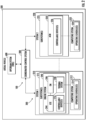
- FIG. 1 provides a block diagram of an integrated system 100 according to one example embodiment of the present subject matter.
- the integrated system 100 includes a plurality of individual systems 200 that are all communicatively coupled with a coordinated control system 300.
- the individual systems 200 can be communicatively coupled with the coordinated control system 300 in any suitable manner, e.g., over a network.
- the individual systems 200 can be linked or in communication with the coordinated control system 300 via any suitable wired and/or wireless communication link.
- the integrated system 100 is communicatively coupled with an upstream system 400, e.g., over a network.
- the integrated system 100 can be an integrated power generation system and the upstream system 400 can be a power generation monitoring center.
- the integrated system 100 can be an integrated propulsion and power system of an aerial vehicle and the upstream system 400 can be a flight management system of the aerial vehicle.
- the integrated system 100 can include any number of individual systems 200.
- the integrated system 100 includes a first individual system 210 and a second individual system 220, and may include other individual systems as represented by an Nth individual system 230.
- the integrated system 100 can include N number of individual systems communicatively coupled with the coordinated control system 300, wherein N is an integer equal to or greater than two (2).
- the individual systems 200 can be power and/or thermal systems.
- Example power and/or thermal systems include, without limitation, a gas turbine engine, an air cycle machine coupled with the gas turbine engine in flow communication, an electric machine, a solar energy system, a wind energy system, a closed-cycle engine, among other possible power and/or thermal systems.
- Each individual system 200 includes a computing system and one or more subsystems.
- the computing system of each individual system 200 can include one or more processors and one or more memory devices.
- the one or more processors and one or more memory devices of a given computing system can be embodied in one or more computing devices, for example.
- Each individual system 200 can include an operating schedule, which can include one or more operating schedules.
- the operating schedule of an individual system 200 can be stored on the one or more memory devices and can be accessed by the one or more processors of the computing system associated with the individual system.
- the one or more subsystems of a given one of the individual systems 200 can be various types of systems, such as turboelectric power systems, electric power systems, thermal systems, etc.
- the subsystems can include one or more controllable devices that may be controlled by their associated computing system.
- the first individual system 210 includes a first computing system 212 having one or more processors 213 and one or more memory devices (not shown).
- the one or more processors 213 and one or more memory devices of the first computing system 212 can be embodied in one or more computing devices, for example.
- the first computing system 212 includes an operating schedule 214.
- the first individual system 210 also includes one or more subsystems 215 and one or more controllable devices 216 associated with the subsystems 215.
- the one or more controllable devices 216 can be controlled based on or according to the operating schedule 214 as will be explained further herein.
- the second individual system 220 includes a second computing system 222 having one or more processors 223 and one or more memory devices (not shown).
- the one or more processors 223 and one or more memory devices of the second computing system 222 can be embodied in one or more computing devices, for example.
- the second computing system 222 includes an operating schedule 224.
- the second individual system 220 also includes one or more subsystems 225 and one or more controllable devices 226 associated with the subsystems 225.
- the one or more controllable devices 226 can be controlled based on or according to the operating schedule 224.
- the controllable devices 216, 226 are operable to change an input and/or output of their associated subsystems 215, 225.
- the first operating schedule 214 includes a plurality of normal schedules in which one or more corresponding primary objective variables are to be targeted.
- the operating constraints for the second operating mode have corresponding revised constraint priorities.
- the schedules and priorities for the second operating mode of the integrated system 100 are labeled in FIG. 1 as "POVs:NOMSCH” and "OPCNSTR:REVPRO" respectively.
- Control references corresponding to a demanded schedule and its respective targeted primary objective variables for a given operating mode of the integrated system 100 can be accessed and retrieved from a given operating schedule by one or more associated processors. Stated differently, control references can be provided from an operating schedule to one or more associated processors based on the demanded schedule and its respective targeted primary objective variables for a given operating mode of the integrated system 100. For instance, as depicted in FIG. 1 , one or more control references (denoted in FIG. 1 as "Ctrl Refs") corresponding to a schedule and its respective targeted primary objective variable are shown being provided from the first operating schedule 214 to the one or more processors 213. The provided control references can be used by the one or more processors 213 to control the first controllable devices 216.
- control references corresponding to a schedule and its respective targeted primary objective variable are shown being provided from the second operating schedule 224 to the one or more processors 223.
- the provided control references can be used by the one or more processors 223 to control the second controllable devices 226.
- one or more constraint references corresponding to the operating constraints associated with operating the second individual system 220 are shown being provided from the second operating schedule 224 to the one or more processors 223.
- one or more constraint priority references corresponding to the operating constraint priorities of the operating constraints associated with operating the second individual system 220 are shown being provided from the second operating schedule 224 to the one or more processors 223.
- the provided constraint references and constraint priority references can be used by the one or more processors 223 to control the second controllable devices 226.
- the computing system 212, 222 of each individual system 210, 220 generates data that is provided to the coordinated control system 300.
- the generated data can include or indicate a status and a prediction associated with an individual system 200.
- the one or more processors 213 of the first computing system 212 generates data that indicates a status and a prediction associated with the first individual system 210.
- the data generated by the one or more processors 213 of the first computing system 212 is provided to and received by the coordinated control system 300, e.g., over a network or data communication link.
- the one or more processors 223 of the second computing system 222 generates data that indicates a status and a prediction associated with the second individual system 220.
- the data generated by the one or more processors 223 is provided to and received by the coordinated control system 300.
- the generated data can include a health status that indicates the health of an individual system or components thereof, e.g., components of their respective subsystems.
- the health status can be generated by one or more processors of an individual system, e.g., based received sensor data and one or more health models, and provided directly to the coordinated control system 300.
- the generated data can include health information indicating the health of an individual system or components thereof. The health information can be provided to a health state module and the health state module can output a health status of the individual system or components thereof. The output health status can then be provided to the coordinated control system 300.
- the data generated by a computing system of an individual system 200 can also include or indicate a prediction associated with the individual system.
- the prediction can indicate a capability of an individual system, or one or more subsystems thereof, to meet a demanded output of the individual system in its current mode of operation.
- the data generated by an individual system can include or indicate a prediction on a capability margin of the individual system, e.g., to meet the demanded output in its current mode of operation.
- the capability margin can be defined as an individual system's capability of meeting the demanded output in its current mode of operation without compromising the safety and reliability of the individual system (e.g., without running afoul of any operating constraints or constraint priorities).
- this can reduce the amount or quantity of data transferred between the individual systems 210, 220 and the coordinated control system 300 of the integrated system 100 and can eliminate or greatly reduce the need to share intellectual property, know-how, and/or other confidential information between entities who have developed and/or are operating the individual systems 210, 220 and coordinated control system 300.
- the coordinated control system 300 is operable to receive one or more mission demands and priorities from the upstream system 400, receive the status and prediction data from the individual systems 210, 220, and output coordinated demands to the individual systems 210, 220 so that the individual systems 210, 220 control their respective controllable devices 216, 226 to meet the mission demands and priorities set forth for the integrated system 100.
- the coordinated control system 300 is described further below.
- the coordinated control system 300 includes the conflict check component 310.
- the status and predictions generated by each individual system 210, 220 are input into the conflict check component 310.
- the conflict check component 310 can be a set of computer-executable instructions, for example.
- a relative status for each of the individual systems 210, 220 can be generated.
- the relative status for each of the individual systems 210, 220 is generated based at least in part on the status and predictions generated by the individual systems 210, 220.
- the conflict check component 310 can utilize the priorities of the primary objective variables for the individual systems 200 and demands for the individual systems 200 set forth by the upstream system 400 to determine the relative status for each of the individual systems 210, 220.
- the relative status generated for each individual system 210, 220 is deemed a "relative status" because the status, capabilities, and constraints of an individual system are considered relative to the status, capabilities, and constraints of other individual systems.
- the status, capabilities, and constraints of each individual system can be considered against the status, capabilities, and constraints of each one of all the other individual systems.
- the status, capabilities, and constraints of the first individual system 210 can be considered relative to the status, capabilities, and constraints of the second individual system 220.
- the status, capabilities, and constraints of the second individual system 220 can be considered relative to the status, capabilities, and constraints of the first individual system 210.
- FIG. 1 if System i is considered relative to System j, and System i and System j interface with one another, one or both of their respective statutes may be impacted by one another.
- System i is a gas turbine engine
- System j is an air cycle machine that interfaces with the gas turbine engine (e.g., as shown in FIG. 2 ).
- the air cycle machine is operable to provide pressurized air bled from the gas turbine engine to a cabin of the aircraft to which the gas turbine engine and the air cycle machine are mounted.
- the relative status generated for each individual system 210, 220 is input into the decision-making component 320 as depicted in FIG. 1 . If an individual system is conflicted, the relative status of that individual system can be reported as "CONFLICTED". The type of conflict can also be reported as part of the relative status. As one example, one type of conflict may be the capability of System i versus the operability of System j. As another example, the type of conflict may be the capability of System i versus the capability of System j. If an individual system is not conflicted, the relative status of that individual system can be reported as "NOT CONFLICTED".
- the decision-making component 320 can be a set of computer-executable instructions, for example. Generally, when the decision-making component 320 is executed (e.g., by one or more processors of the coordinated control system 300), an operating case code is determined. The operating case code can include or set forth an operating mode in which each individual system 210, 220 is to operate at the next operation step. Furthermore, when the decision-making component 320 is executed (e.g., by one or more processors of the coordinated control system 300), an allowed demand for each individual system 210, 220 is determined. The operating case and mode and allowed demand for a given individual system is determined based at least in part on the relative status of the given individual system and the mission demands and priorities received from the upstream system 400.
- the determined operating modes are sent over the network from the coordinated control system 300 to the individual systems 200.
- an operating mode determined for the first individual system 210 denoted as SYS 1 MODE in FIG. 1 , is output to the first individual system 210.
- the operating mode can be sent as an operating case code determined by the decision-making component 320.
- the first computing system 212 of the first individual system 210 receives the determined operating mode.
- the first individual system 210 can receive one or more signals indicating the determined operating mode.
- an operating mode determined for the second individual system 220 is output to the second individual system 220.
- an operating mode determined for the Nth individual system 230 is output to the Nth individual system 230.
- the operating modes of the second and Nth individual systems 220, 230 can be sent as an operating case code determined by the decision-making component 320.
- a same operating case code can be sent to each individual system 210, 220, or alternatively, the operating case code determined by the decision-making component 320 can be partitioned so that only the relevant part of operating case code is sent to the appropriate individual system.
- an allowed demand for each individual system 210, 220 is determined.
- the allowed demand for a given individual system is determined based at least in part on the relative status of the given individual system and the mission demands and priorities received from the upstream system 400.
- the allowed demands are input into a mapping component 330 as shown in FIG. 1 .
- an allowed demand can be a demanded power output of an individual system (e.g., in kW).
- an allowed demand can be a demanded thrust output of an aviation gas turbine engine.
- the mapping component 330 receives the allowed demands for the individual systems 210, 220, which are determined based at least in part on the relative status of the given individual system and the mission demands and priorities received from the upstream system 400, and maps them to their respective individual systems demands, or rather, to control parameters that can be controlled to meet the respective individual systems demands. Generally, the mapping component 330 determines where in a particular schedule and under what constraints an individual system is to run or operate based on its corresponding allowed demand. When the allowed demands are mapped to the individual system demands, an individual system demand for each of the individual systems 210, 220 can be determined.
- the mapping component 330 can map an allowed demand (e.g., a power demand) associated with a gas turbine engine to a throttle input or thrust demand of the gas turbine engine.
- the mapping component 330 can map an allowed demand (e.g., a cooling demand) associated with an ACM to a temperature of the fluid being moved by the ACM or a mass flow rate thereof.
- the determined individual system demands for each of the individual systems 210, 220 can be output to the computing systems 212, 222 of the individual systems 210, 220.
- the individual system demand for the first individual system 210 denoted as SYS 1 DMD
- the individual system demand for the second individual system 220 is output to the second computing system 222.
- the individual system demand for the Nth individual system 230 is output to the computing system of the Nth individual system 230.
- the one or more subsystems 215 of the first individual system 210 include an engine system 240.
- the engine system 240 includes a gas turbine engine 244 and an electric machine 246 operatively coupled thereto.
- the electric machine 246 is operable to generate electrical power when driven by the gas turbine engine 244 and/or is operable to drive the gas turbine engine 244 in a drive or motoring mode.
- the engine system 240 can be a hybrid-electric engine system.
- the engine system 240 also includes one or more controllable devices 216 and a thermal system 248.
- the one or more controllable devices can include, without limitation, a fuel regulator operable to control the fuel flow to a combustor of the gas turbine engine 244, valves, a power converter 216A associated with the electric machine 246, etc. Electric power generated by the electric machine 246 can be provided to one or more power-consuming devices via a power bus 208.
- the power converter 216A can be controlled, e.g., by a computing system of the first individual system 210, to control electric power provided to or from the electric machine 246.
- each one of the individual power and/or thermal systems 220 is communicatively coupled with the coordinated control system 300.
- Coordinated control of the individual power and/or thermal systems 220, or electric power generation, storage, demand and distribution between them, can be achieved with the coordinated control system 300 according to the inventive aspects as described above with reference to the example implementations of FIGS. 2 and 3 .
- Example conflicts of interest may include, e.g., self-conflicts, electric power supply capability of the electric machine 246 and/or one or more batteries 234 versus power demand capability of the electric machine 227, operability versus capability conflicts, etc.
- the decision-making component 320 ( FIG. 1 ) can then generate the allowed demands and operating case codes, which include operating modes for the individual power and/or thermal systems 200 given the relative statuses, demands and priorities received from the upstream system 400, and predetermined rules.
- the allowed demands can be mapped, and mapped individual system demands can be output to the individual power and/or thermal systems 200.
- the individual power and/or thermal systems 200 can control themselves using their own internal control schemes or implementation details but in a coordinated manner via the coordinated control system 300.
- FIG. 5 provides a flow diagram of an example method (600) of coordinating control of an integrated system having a coordinated control system and a plurality of individual systems communicatively coupled thereto according to an example embodiment of the present subject matter.
- the method (600) of FIG. 5 can be implemented using, for instance, the integrated system 100 or portions thereof described herein.
- FIG. 5 depicts actions performed in a particular order for purposes of illustration and discussion. Those of ordinary skill in the art, using the disclosures provided herein, will understand that various steps of any of the methods disclosed herein can be modified in various ways without deviating from the scope of the present disclosure.
- the integrated system can be configured as shown in FIG. 2 .
- the one or more mission demands received by the coordinated control system 300 from the upstream system 400 can set forth that the integrated system 100 is to provide a demanded thrust and a demanded pressure in an enclosed area of the aerial vehicle 500 to which the individual systems 200 are mounted.
- the upstream system 400 can be a flight management system or other vehicle control system, for example.
- the method (600) includes receiving, by the coordinated control system from each one of a plurality of individual systems communicatively coupled with the coordinated control system, data that includes an operating mode status and a prediction on a capability of an individual system of the plurality of individual systems to meet a demand.
- the computing system of each individual system can generate data that includes the operating mode status and the prediction on the capability of the individual system associated with the computing system to meet the demand. Predictions on operability and meeting constraints can also be part of the data reported to the coordinated control system.
- the plurality of individual systems of an integrated system can include a first individual system having one or more subsystems and a second individual system having one or more subsystems interfacing with at least one of the subsystems of the first individual system.
- the one or more subsystems of the first individual system can include a gas turbine engine and the one or more subsystems of the second individual system can include an air cycle machine that interfaces with the gas turbine engine (e.g., as shown in FIG. 2 ).
- the first individual system and the second individual system can have an associated interactive constraint.
- the interactive constraint can be an allowable air bleed mass flow constraint that impacts both systems.
- the method (600) includes determining, by the coordinated control system and for each of the plurality of individual systems, an operating mode and an allowed demand, the operating mode and the allowed demand for a given individual system of the plurality of individual systems being determined based at least in part on the relative status generated for the given individual system and the one or more mission demands and the one or more mission priorities received from the upstream system.
- the operating modes and allowed demands can be generated based at least in part on one or more predetermined rules.
- the predetermined rules can set forth the rules for how the coordinated control system is to select operating modes and/or allowed demands given the operating conditions, relative statuses of the individual systems, type of conflict of interest, etc.
- the coordinated control system 300 can include the decision-making component 320 that, when executed, determines an allowed demand for each individual system 210, 220.
- the allowed demand for a given individual system is determined based at least in part on the relative status of the given individual system and the mission demands and priorities received from the upstream system 400.
- an allowed demand can be a demanded power output of an individual system (e.g., in kW).
- an allowed demand can be a demanded thrust output of an aviation gas turbine engine.
- the mapping component 330 of the coordinated control system 300 can receive the allowed demands for the individual systems 210, 220.
- an operating mode for each individual system 210, 220 is determined based at least in part on the relative status generated for the individual systems 210, 220 and the one or more mission demands and the one or more mission priorities received from the upstream system 400.
- the operating mode of one or more of the individual systems 210, 220 can be changed from their reported statuses.
- at least one of the operating modes determined for the plurality of individual systems 210, 220 is changed from an operating mode associated with the operating mode status received from the individual system as part of the data.
- the solar power system and the wind power system can be operate in full sunshine and strong wind operating modes, respectively, and the engine system can operate in a low power or low capability operating mode. Then, environmental conditions may change, causing the solar power system to report its status as negligible sunshine, which consequently would result in a different relative status of the solar power system.
- the coordinated control system can coordinate or change the operating mode of the engine system from a reported status of low power to medium or high power mode to assist the wind power system in meeting the demanded electrical power.
- the operating mode determined for the individual systems can be changed from their respective reported statuses to meet the mission demands and priorities.
- the coordinated control system 300 thus enables transient control of the individual systems.
- the method (600) includes mapping, by the coordinated control system, the allowed demand for each individual system of the plurality of individual systems to respective individual system demands.
- the mapping component 330 of the coordinated control system 300 can receive the allowed demands for the individual systems 210, 220, which are determined based at least in part on the relative status of the given individual system and the mission demands and priorities received from the upstream system 400 as noted above.
- the mapping component 330 can then map the allowed demands to their respective individual systems demands.
- An individual system demand for each of the individual systems 210, 220 can be determined.
- FIG. 6 provides a block diagram of an example computing system 700 that can be used to implement methods and systems described herein according to example embodiments of the present subject matter.
- the computing system 700 is one example of a suitable computing system for implementing the computing elements described herein.
- the computing systems 212, 222, the coordinated control system 300, other computing devices of the integrated system 100, and the upstream system 400 noted herein can be constructed and operate in a similar manner as the computing system 700.
- the computing system 700 includes one more computing device(s) 702.
- the one or more computing device(s) 702 can include one or more processor(s) 704 and one or more memory device(s) 706.
- the one or more processor(s) 704 can include any suitable processing device, such as a microprocessor, microcontroller, integrated circuit, logic device, or other suitable processing device.
- the one or more memory device(s) 706 can include one or more computer-readable medium, including, but not limited to, non-transitory computer-readable medium or media, RAM, ROM, hard drives, flash drives, and other memory devices, such as one or more buffer devices.
- the memory device(s) 706 can further store data 710 that can be accessed by the processor(s) 704.
- the data 710 can include received data, such as mission demands and priorities, the status and predictions associated with the individual systems, schedules, and operating constraints, etc.
- the data 710 can include one or more table(s), function(s), algorithm(s), model(s), equation(s), etc. according to example embodiments of the present disclosure.
- the one or more computing device(s) 702 can also include a communication interface 712 used to communicate, for example, with other components of the integrated system 100 or the upstream system 400.
- the communication interface 712 can include any suitable components for interfacing with one or more network(s), including for example, transmitters, receivers, ports, controllers, antennas, or other suitable components.
Landscapes
- Engineering & Computer Science (AREA)
- General Engineering & Computer Science (AREA)
- Combustion & Propulsion (AREA)
- Chemical & Material Sciences (AREA)
- Theoretical Computer Science (AREA)
- Aviation & Aerospace Engineering (AREA)
- Mechanical Engineering (AREA)
- General Physics & Mathematics (AREA)
- Physics & Mathematics (AREA)
- Pulmonology (AREA)
- General Health & Medical Sciences (AREA)
- Health & Medical Sciences (AREA)
- Automation & Control Theory (AREA)
- Supply And Distribution Of Alternating Current (AREA)
Abstract
Description
- The present subject matter relates generally to systems and methods of coordinating the power and thermal management needs and control of a plurality of power and/or thermal systems.
- Some individual systems coupled together or that otherwise interface with one another do not have any means of coordinating control between them. For instance, an aviation gas turbine engine mounted to an aircraft may be coupled to an air cycle machine that moves pressurized air bled from the gas turbine engine to a cabin of the aircraft. The air cycle machine may also provide cooling to the gas turbine engine. Conventionally, air is bled from the gas turbine engine to meet the pressurized air demanded for the cabin without regard for the efficiency penalty on the engine. The lack of coordinated control of these individual systems can cause such systems to operate inefficiently, among other drawbacks.
- Accordingly, a system that offers coordinated control of such individual systems would be a welcome addition to the art.
- A full and enabling disclosure of the present subject matter, including the best mode thereof, directed to one of ordinary skill in the art, is set forth in the specification, which makes reference to the appended figures, in which:
-
FIG. 1 provides a block diagram of an integrated system according to one example embodiment of the present subject matter; -
FIG. 2 provides a block diagram of one example embodiment of an integrated system; -
FIG. 3 provides a flow diagram depicting one example manner in which coordinated control of the integrated system ofFIG. 2 can be implemented; -
FIG. 4 provides a block diagram of another example embodiment of an integrated system; -
FIG. 5 provides a flow diagram of an example method of operating an integrated system according to one example embodiment of the present subject matter; and -
FIG. 6 provides a schematic view of a computing system for implementing one or more aspects of the present disclosure according to example embodiments of the present subject matter. - Reference will now be made in detail to present embodiments of the disclosure, one or more examples of which are illustrated in the accompanying drawings. The detailed description uses numerical and letter designations to refer to features in the drawings. Like or similar designations in the drawings and description have been used to refer to like or similar parts of the disclosure.
- As used herein, the terms "first", "second", and "third" may be used interchangeably to distinguish one component from another and are not intended to signify location or importance of the individual components. The terms "upstream" and "downstream" refer to the relative flow direction with respect to fluid flow in a fluid pathway. For example, "upstream" refers to the flow direction from which the fluid flows, and "downstream" refers to the flow direction to which the fluid flows.
- Some individual systems coupled together or that otherwise interface with one another do not have any means of coordinating control between them. For instance, an aviation gas turbine engine mounted to an aircraft may be coupled to an air cycle machine that moves pressurized air bled from the gas turbine engine to a cabin of the aircraft. The air cycle machine may also provide cooling to the gas turbine engine. Conventionally, air is bled from the gas turbine engine to meet the pressurized air demanded for the cabin without regard for the efficiency penalty on the engine. The lack of coordinated control of these individual systems can cause such systems to operate inefficiently, among other drawbacks.
- Some individual systems are coupled together as part of a distributed control system. The individual systems may each be in communication with a main controller operable to control the operation of the individual systems. Such distributed systems can present a number of control and thermal management challenges. For instance, individual systems may have competing or conflicting interests (control objectives and constraints) in meeting their demands. Conventionally, the main controller receives detailed raw data from the individual systems and generates instructions for optimizing the thermal and power aspects of all the individual systems using its own models and control logic.
- Using such control schemes can require the transfer of significant amounts of data between the main controller and the individual systems, which can increase the complexity and cost of the system hardware and may require significant processing resources. Further, using such control schemes can require that the entity operating the main controller be privy to the control implementation details of all the individual systems, e.g., in order to optimize the thermal and power aspects of the individual systems. This may be undesirable, especially when the entity that developed and/or that operates the main controller is different than an entity or entities that developed and/or operate the individual systems. In addition, such control schemes typically lack coordinated control of the individual systems.
- Accordingly, a system that offers coordinated control of such individual systems is presented herein. Particularly, aspects of the present disclosure are directed to an integrated system having a plurality of individual systems and a coordinated control system for controlling the plurality of individual systems to meet mission demands and priorities. Notably, the coordinated control system is configured to control the individual systems without requiring implementation details pertaining to how the individual systems intend to meet the mission demands and priorities. Rather, the individual systems provide their respective statuses and predictions on meeting their respective demands, operability, and constraints to the coordinated control system, and the coordinated control system controls the individual systems in a controlled manner based at least in part on these received inputs and mission demands and priorities set forth by an upstream system. Accordingly, advantageously, there is no need or a reduced need to share the control details of an individual system with the coordinated control system. A method and non-transitory computer-readable medium that enable or facilitate coordinated control of a plurality of individual systems are also provided.
- In one aspect, an integrated system is provided. The integrated system includes a plurality of individual systems communicatively coupled with a coordinated control system. Each individual system can include a computing system, an operating schedule, one or more subsystems, such as one or more power and/or thermal systems, and one or more controllable devices associated with the subsystems. Generally, the coordinated control system controls the plurality of individual systems in a coordinated manner.
- The coordinated control system is communicatively coupled with an upstream system. The coordinated control system receives mission demands and mission priorities from the upstream system. The coordinated control system also receives data from each individual system. The data includes or indicates a status and a prediction associated with the individual system. The status can be an operating mode status and the prediction can indicate the capability of an individual system to meet a demand, such as a demanded output of one or more of its subsystems. Thus, the coordinated control system can receive, from each individual system, data indicating the operating mode in which the individual system is operating and the individual system's capability to meet the demand. An individual system's ability to meet a demand may depend on its current operating mode, operating constraints, and operating constraint priorities. The prediction as to the individual system's capability can be in the form of a capability margin of the individual system.
- Upon receiving the data from each individual system, one or more processors of the coordinated control system execute a conflict check component to perform a conflict of interest check to ultimately determine a relative status of each individual system. The relative status for a given individual system is determined based at least in part on the received data that includes or indicates the status and the prediction associated with the individual system as well as the data received from other individual systems. For instance, one or more operating constraints or constraint priorities of one individual system may directly impact the operation of one or more other individual systems, particularly when the individual systems interface or are coupled with one another. These interactive constraints are considered, and, thus the statuses determined for the individual systems are deemed "relative" as the coordinated control system considers the status and predictions of an individual system as well as the status and constraints of other individual systems relative to that individual system.
- A relative status of an individual system can be determined as "Conflicted" in instances in which the individual system's capability to meet its demand, operability, or constraints conflicts with another individual system's capability to meet its demand, operability, or constraints. When one or more of the individual systems are conflicted, one or more of the individual systems can be controlled to operate in a different operating mode for the next operation step, for example. This may eliminate or otherwise mitigate the conflict of interest between the individual systems. A relative status of an individual system can be determined as "Not Conflicted" in instances in which the individual system's capability to meet its demand, operability, or constraints does not conflict with another individual system's capability to meet its demand, operability, or constraints. When the individual systems are not conflicted, the individual systems can be controlled to continue operating in their respective operating modes, for example.
- The one or more processors of the coordinated control system execute a decision-making component to determine an operating case code, which may include an individual operating case and operating mode for each individual system. The decision-making component may also determine allowed demands for the individual systems. The operating modes and the allowed demands for the individual systems are determined based at least in part on the determined relative statuses for the individual systems and the mission demands and priorities received from the upstream system. For instance, the mission demands can include demands for the individual systems and the priorities can set forth which primary objective variables of the individual systems are to be prioritized. The operating modes determined for the individual systems are output to their respective individual systems. Particularly, the operating modes determined for the individual systems are output to the computing systems of the individual systems. Control, constraint, and constraint priority references associated with one or more schedules and constraints associated with the determined operating mode are provided to the respective computing systems.
- The one or more processors of the coordinated control system execute a mapping component to map the allowed demands for the individual systems with individual system demands. The mapping component can map the allowed demands for the individual systems with individual system demands using a matrix-mapping technique. The allowed demands are mapped to individual system demands predetermined to meet or best meet the allowed demand. For instance, if an allowed demand for an individual system is determined to be a determined number of kilowatts or kilowatt hours, the allowed demand is mapped to an individual system demand for the individual system that meet or best achieves the demanded determined number of kilowatts or kilowatt hours. The mapped or determined individual system demands for the individual systems are output to the computing systems of the individual systems. Based on the individual system demands and references received from their respective operating schedules, the computing systems control one or more controllable devices of their respective individual systems to ultimately meet the mission demand of the integrated system.
- The coordinated control system controls the individual systems in a coordinated manner. The coordinated control system can control some or all performance objectives of the individual systems, including their power and/or thermal management objectives. Other performance objectives can include propulsion or thrust objectives, particularly where one or more of the individual systems includes a thrust producer or propulsor, such as an aviation gas turbine engine. The coordinated control system can control the individual systems in a coordinated manner in that the individual systems are controlled based on the mission demands and priorities and the allowed demands, which are determined based at least in part on the relative status of each individual system. The relative status of each individual system considers an individual system's status and predictions as to its capability margin, which is based on its operating constraint predictions and any relevant interactive constraints that impact the individual system due to its coupling or interface with another individual system. Thus, the resultant individual system demands are selected or determined based on a collective and coordinated control scheme.
- Notably, advantageously and as a technical effect of the coordinated control schemes described herein, the implementation details of the individual systems (e.g., the physics upon which an individual system is controlled) can remain privy to only the entity or entities of the individual systems-there is no need or a reduced need to share the control details of an individual system with the coordinated control system. In some embodiments, to coordinate control of the individual systems, the coordinated control system need only know the status or mode of each individual system, predictions as to the capability margin, operability, and constraints of each individual system, and the overall upstream system demands to ultimately coordinate control of the individual systems to meet the demands and priorities of the upstream system. Accordingly, the integrated system and methods described herein provide a coordinated control system that coordinates control of the individual systems such that the individual systems are controlled using their own internal control schemes or implementation details in different operating conditions.
-
FIG. 1 provides a block diagram of anintegrated system 100 according to one example embodiment of the present subject matter. Theintegrated system 100 includes a plurality ofindividual systems 200 that are all communicatively coupled with acoordinated control system 300. Theindividual systems 200 can be communicatively coupled with the coordinatedcontrol system 300 in any suitable manner, e.g., over a network. Theindividual systems 200 can be linked or in communication with the coordinatedcontrol system 300 via any suitable wired and/or wireless communication link. Theintegrated system 100 is communicatively coupled with anupstream system 400, e.g., over a network. As one example, theintegrated system 100 can be an integrated power generation system and theupstream system 400 can be a power generation monitoring center. As another example, theintegrated system 100 can be an integrated propulsion and power system of an aerial vehicle and theupstream system 400 can be a flight management system of the aerial vehicle. - The
integrated system 100 can include any number ofindividual systems 200. For instance, as depicted inFIG. 1 , theintegrated system 100 includes a firstindividual system 210 and a secondindividual system 220, and may include other individual systems as represented by an Nthindividual system 230. In some embodiments, theintegrated system 100 can include N number of individual systems communicatively coupled with the coordinatedcontrol system 300, wherein N is an integer equal to or greater than two (2). Theindividual systems 200 can be power and/or thermal systems. Example power and/or thermal systems include, without limitation, a gas turbine engine, an air cycle machine coupled with the gas turbine engine in flow communication, an electric machine, a solar energy system, a wind energy system, a closed-cycle engine, among other possible power and/or thermal systems. - Each
individual system 200 includes a computing system and one or more subsystems. The computing system of eachindividual system 200 can include one or more processors and one or more memory devices. The one or more processors and one or more memory devices of a given computing system can be embodied in one or more computing devices, for example. Eachindividual system 200 can include an operating schedule, which can include one or more operating schedules. The operating schedule of anindividual system 200 can be stored on the one or more memory devices and can be accessed by the one or more processors of the computing system associated with the individual system. The one or more subsystems of a given one of theindividual systems 200 can be various types of systems, such as turboelectric power systems, electric power systems, thermal systems, etc. The subsystems can include one or more controllable devices that may be controlled by their associated computing system. - Particularly, as depicted in
FIG. 1 , the firstindividual system 210 includes afirst computing system 212 having one ormore processors 213 and one or more memory devices (not shown). The one ormore processors 213 and one or more memory devices of thefirst computing system 212 can be embodied in one or more computing devices, for example. Thefirst computing system 212 includes anoperating schedule 214. The firstindividual system 210 also includes one ormore subsystems 215 and one or morecontrollable devices 216 associated with thesubsystems 215. The one or morecontrollable devices 216 can be controlled based on or according to theoperating schedule 214 as will be explained further herein. - Similarly, the second
individual system 220 includes asecond computing system 222 having one ormore processors 223 and one or more memory devices (not shown). The one ormore processors 223 and one or more memory devices of thesecond computing system 222 can be embodied in one or more computing devices, for example. Thesecond computing system 222 includes anoperating schedule 224. The secondindividual system 220 also includes one ormore subsystems 225 and one or morecontrollable devices 226 associated with thesubsystems 225. The one or morecontrollable devices 226 can be controlled based on or according to theoperating schedule 224. Thecontrollable devices subsystems - Each
operating schedule integrated system 100. Each set of schedules and constraint priorities includes one or more target primary objectives and constraint priorities that the corresponding individual system is to target or achieve for a particular operating mode of theintegrated system 100. - For instance, as depicted in
FIG. 1 , thefirst operating schedule 214 of the firstindividual system 210 includes a set of schedules and constraint priorities for each operating mode of theintegrated system 100. Particularly, for a first operating mode of theintegrated system 100, thefirst operating schedule 214 includes a plurality of normal schedules in which one or more corresponding primary objective variables (labeled as POVs inFIG. 1 ) are to be targeted. The operating constraints for the first operating mode have corresponding normal constraint priorities. The schedules and priorities for the first operating mode of theintegrated system 100 are labeled inFIG. 1 as "POVs:NOMSCH" and "OPCNSTR:NOMPRO" respectively. For a second operating mode of theintegrated system 100, thefirst operating schedule 214 includes a plurality of normal schedules in which one or more corresponding primary objective variables are to be targeted. The operating constraints for the second operating mode have corresponding revised constraint priorities. The schedules and priorities for the second operating mode of theintegrated system 100 are labeled inFIG. 1 as "POVs:NOMSCH" and "OPCNSTR:REVPRO" respectively. - Further, for a third operating mode of the
integrated system 100, thefirst operating schedule 214 includes a plurality of revised schedules in which one or more corresponding primary objective variables are to be targeted, e.g., when a conflict of interest arises between the firstindividual system 210 and the secondindividual system 220. The operating constraints for the third operating mode have corresponding normal constraint priorities. The revised schedules and priorities for the third operating mode of theintegrated system 100 are labeled inFIG. 1 as "POVs:REVSCH" and "OPCNSTR:NOMPRO" respectively. For a fourth operating mode of theintegrated system 100, thefirst operating schedule 214 includes a plurality of revised schedules in which one or more corresponding primary objective variables are to be targeted, e.g., when a conflict of interest arises. The operating constraints for the fourth operating mode have corresponding revised constraint priorities. The revised schedules and revised priorities for the fourth operating mode of theintegrated system 100 are labeled inFIG. 1 as "POVs:REVSCH" and "OPCNSTR:REVPRO" respectively. Although schedules and priorities for four operating modes of theintegrated system 100 are depicted, it will be appreciated that thefirst operating schedule 214 can include schedules and priorities for more or less than four (4) operating modes of theintegrated system 100. - As further shown in
FIG. 1 , thesecond operating schedule 224 of the secondindividual system 220 also includes a set of schedules and constraint priorities for each operating mode of theintegrated system 100. As will be appreciated, the schedules and priorities of thesecond operating schedules 224 can differ from the schedules and constraint priorities of thefirst operating schedule 214. - Control references corresponding to a demanded schedule and its respective targeted primary objective variables for a given operating mode of the
integrated system 100 can be accessed and retrieved from a given operating schedule by one or more associated processors. Stated differently, control references can be provided from an operating schedule to one or more associated processors based on the demanded schedule and its respective targeted primary objective variables for a given operating mode of theintegrated system 100. For instance, as depicted inFIG. 1 , one or more control references (denoted inFIG. 1 as "Ctrl Refs") corresponding to a schedule and its respective targeted primary objective variable are shown being provided from thefirst operating schedule 214 to the one ormore processors 213. The provided control references can be used by the one ormore processors 213 to control the firstcontrollable devices 216. Furthermore, one or more control references corresponding to a schedule and its respective targeted primary objective variable are shown being provided from thesecond operating schedule 224 to the one ormore processors 223. The provided control references can be used by the one ormore processors 223 to control the secondcontrollable devices 226. - In addition, constraint references corresponding to the operating constraints associated with operating the individual system for a given operating mode of the
integrated system 100 can be provided from a given operating schedule to one or more corresponding processors. For instance, as depicted inFIG. 1 , one or more constraint references (denoted inFIG. 1 as "CNSTR Refs") corresponding to the operating constraints associated with operating the firstindividual system 210 are shown being provided from thefirst operating schedule 214 to the one ormore processors 213. Further, constraint priority references corresponding to the operating constraint priorities of the operating constraints associated with operating the individual system for a given operating mode of theintegrated system 100 can be provided from a given operating schedule to one or more corresponding processors. For instance, as depicted inFIG. 1 , one or more constraint priority references (denoted inFIG. 1 as "CNSTR PRO Refs") corresponding to the operating constraint priorities of the operating constraints associated with operating the firstindividual system 210 are shown being provided from thefirst operating schedule 214 to the one ormore processors 213. The provided constraint references and constraint priority references can be used by the one ormore processors 213 to control the firstcontrollable devices 216. - For the second
individual system 220, one or more constraint references corresponding to the operating constraints associated with operating the secondindividual system 220 are shown being provided from thesecond operating schedule 224 to the one ormore processors 223. Moreover, one or more constraint priority references corresponding to the operating constraint priorities of the operating constraints associated with operating the secondindividual system 220 are shown being provided from thesecond operating schedule 224 to the one ormore processors 223. The provided constraint references and constraint priority references can be used by the one ormore processors 223 to control the secondcontrollable devices 226. - Notably, for the depicted embodiment of
FIG. 1 , theindividual systems 200 in theintegrated system 100 are individually controlled based on their own individual control schemes. Stated another way, eachindividual system integrated system 100 can be controlled based on its own physics and working mechanism. Particularly, theindividual systems respective computing systems respective operating schedules control system 300; rather, as noted, the control and constraint references are provided from an operating schedule of an individual system. Advantageously, as will be explained in more detail herein, providing control and constraint references from the operating schedule of a givenindividual system 200 can reduce the amount or quantity of data transferred between theindividual systems coordinated control system 300 of theintegrated system 100. Further, where individual systems and/or the coordinatedcontrol system 300 are developed and/or operated by different entities, the need to share intellectual property, know-how, and/or other confidential information is eliminated or greatly reduced because eachindividual system 200 is controlled based on its own physics or internal control scheme. - In operation, the
computing system individual system control system 300. The generated data can include or indicate a status and a prediction associated with anindividual system 200. For the depicted embodiment ofFIG. 1 , the one ormore processors 213 of thefirst computing system 212 generates data that indicates a status and a prediction associated with the firstindividual system 210. The data generated by the one ormore processors 213 of thefirst computing system 212 is provided to and received by the coordinatedcontrol system 300, e.g., over a network or data communication link. Similarly, the one ormore processors 223 of thesecond computing system 222 generates data that indicates a status and a prediction associated with the secondindividual system 220. The data generated by the one ormore processors 223 is provided to and received by the coordinatedcontrol system 300. - In some embodiments, the generated data can include or indicate an operating mode status of an individual system. An individual system can be operable in a plurality of different operating modes. For example, an individual system can be operable in a first operating mode, a second operating mode, a third operating mode, etc. The operating mode status provided to the coordinated
control system 300 can indicate the operating mode in which the individual system is currently operating. - Further, in some embodiments, the generated data can include a health status that indicates the health of an individual system or components thereof, e.g., components of their respective subsystems. In some embodiments, the health status can be generated by one or more processors of an individual system, e.g., based received sensor data and one or more health models, and provided directly to the coordinated
control system 300. In other embodiments, the generated data can include health information indicating the health of an individual system or components thereof. The health information can be provided to a health state module and the health state module can output a health status of the individual system or components thereof. The output health status can then be provided to the coordinatedcontrol system 300. - For instance, as depicted in
FIG. 1 , the firstindividual system 210 can include ahealth state module 212A that can output a health status of the firstindividual system 210 or components thereof. Likewise, the secondindividual system 220 can include ahealth state module 222A that can output a health status of the secondindividual system 220 or components thereof. The operating mode status and/or the health status associated with an individual system can be used by the coordinatedcontrol system 300, e.g., to make control decisions. - Moreover, as noted above, the data generated by a computing system of an
individual system 200 can also include or indicate a prediction associated with the individual system. The prediction can indicate a capability of an individual system, or one or more subsystems thereof, to meet a demanded output of the individual system in its current mode of operation. Stated another way, the data generated by an individual system can include or indicate a prediction on a capability margin of the individual system, e.g., to meet the demanded output in its current mode of operation. The capability margin can be defined as an individual system's capability of meeting the demanded output in its current mode of operation without compromising the safety and reliability of the individual system (e.g., without running afoul of any operating constraints or constraint priorities). In this manner, the computing system of an individual system can track the current output of the individual system relative to the demanded output. Accordingly, as will be explained further below, if the coordinatedcontrol system 300 receives a mission demand that would cause an individual system to exceed its predicted capability, the coordinatedcontrol system 300 may request a new operating mode for that individual system. In some embodiments, the prediction of the capability margin can take into account one or more operability margins and/or one or more constraint margins associated with the individual system. - Notably, for the depicted embodiment of
FIG. 1 , theindividual systems control system 300. With such information or data, the coordinatedcontrol system 300 can make control decisions to, e.g., change a demanded output of an individual system or change an operating mode of an individual system. The coordinatedcontrol system 300 can do so without knowing how the respective individual systems plan or seek to accomplish these tasks. The implementation details to achieve a change in demanded output or a change in operating mode are kept by the individual system-the implementation details are not shared with the coordinatedcontrol system 300. Accordingly, advantageously, this can reduce the amount or quantity of data transferred between theindividual systems coordinated control system 300 of theintegrated system 100 and can eliminate or greatly reduce the need to share intellectual property, know-how, and/or other confidential information between entities who have developed and/or are operating theindividual systems control system 300. - Generally, the coordinated
control system 300 is operable to receive one or more mission demands and priorities from theupstream system 400, receive the status and prediction data from theindividual systems individual systems individual systems controllable devices integrated system 100. The coordinatedcontrol system 300 is described further below. - With reference still to
FIG. 1 , the coordinatedcontrol system 300 receives one or more mission demands and priorities from theupstream system 400. The one or more mission demands and priorities indicate the desired output of theintegrated system 100 as well as a desired manner or method in which theintegrated system 100 is to prioritize certain objective variables to achieve the desired output. For instance, the one or more mission demands received from theupstream system 400 can indicate that theintegrated system 100 is to provide a particular power capability for downstream needs (e.g., a demanded kilowatt-hour kWh). As another example, the one or more mission demands received from theupstream system 400 can indicate that theintegrated system 100 is to provide a certain thrust output. The one or more mission priorities can set forth priorities for primary objective variables (labeled as POVs inFIG. 1 ) for individual systems for given operating conditions as demands (labeled as DMDs inFIG. 1 ) for theindividual systems 200. Aconflict check component 310 and a decision-making component 320 of the coordinatedcontrol system 300 can receive the mission demands and priorities. - As further shown in
FIG. 1 , the coordinatedcontrol system 300 includes theconflict check component 310. The status and predictions generated by eachindividual system conflict check component 310. Theconflict check component 310 can be a set of computer-executable instructions, for example. Generally, when theconflict check component 310 is executed (e.g., by one or more processors of the coordinated control system 300), a relative status for each of theindividual systems individual systems individual systems conflict check component 310 can utilize the priorities of the primary objective variables for theindividual systems 200 and demands for theindividual systems 200 set forth by theupstream system 400 to determine the relative status for each of theindividual systems - The relative status generated for each
individual system individual system 210 can be considered relative to the status, capabilities, and constraints of the secondindividual system 220. The status, capabilities, and constraints of the secondindividual system 220 can be considered relative to the status, capabilities, and constraints of the firstindividual system 210. - Considering the status, capabilities, and constraints of the individual systems relative to one another can impact the "relative status" of one or more of the
individual systems FIG. 1 , if System i is considered relative to System j, and System i and System j interface with one another, one or both of their respective statutes may be impacted by one another. For example, suppose System i is a gas turbine engine and System j is an air cycle machine that interfaces with the gas turbine engine (e.g., as shown inFIG. 2 ). Further suppose that the air cycle machine is operable to provide pressurized air bled from the gas turbine engine to a cabin of the aircraft to which the gas turbine engine and the air cycle machine are mounted. In such an example, an allowable air bleed mass flow constraint associated with the air cycle machine can directly affect an operating temperature constraint associated the gas turbine engine, and this may impact the status of the gas turbine engine and/or the air cycle machine. If two systems do not interface with one another, their respective statuses may not be impacted by one another. The allowable air bleed mass flow constraint associated with the air cycle machine and the operating temperature constraint associated the gas turbine engine can be identified or predetermined as interactive constraints. In some instances, there may be one or a plurality of interactive constraints between or associated with two individual systems. In some instances, there may be no interactive constraints between or associated with two individual systems. - The relative status generated for each
individual system making component 320 as depicted inFIG. 1 . If an individual system is conflicted, the relative status of that individual system can be reported as "CONFLICTED". The type of conflict can also be reported as part of the relative status. As one example, one type of conflict may be the capability of System i versus the operability of System j. As another example, the type of conflict may be the capability of System i versus the capability of System j. If an individual system is not conflicted, the relative status of that individual system can be reported as "NOT CONFLICTED". - The decision-
making component 320 can be a set of computer-executable instructions, for example. Generally, when the decision-making component 320 is executed (e.g., by one or more processors of the coordinated control system 300), an operating case code is determined. The operating case code can include or set forth an operating mode in which eachindividual system making component 320 is executed (e.g., by one or more processors of the coordinated control system 300), an allowed demand for eachindividual system upstream system 400. - For instance, when a conflict of interest exists between two or more individual systems, the operating mode for one or more of the conflicted individual systems may be changed, e.g., from a first operating mode to a second operating mode. The operating mode that is switched or changed may depend on the priorities received from the
upstream system 400. For instance, theupstream system 400 may prioritize thrust output of one individual system over the cooling capability of another individual system, and based on these priorities, the operating mode of the individual system providing cooling capability may be changed even if it makes the cooling capability less effective, which may allow or help the individual system providing the thrust output to meet the demanded thrust. The allowed demands for the individual systems may be determined based at least in part on the mission demands received from theupstream system 400 and the relative status of theindividual systems 200. - As further shown in
FIG. 1 , the determined operating modes are sent over the network from the coordinatedcontrol system 300 to theindividual systems 200. Particularly, an operating mode determined for the firstindividual system 210, denoted asSYS 1 MODE inFIG. 1 , is output to the firstindividual system 210. The operating mode can be sent as an operating case code determined by the decision-making component 320. Thefirst computing system 212 of the firstindividual system 210 receives the determined operating mode. For example, the firstindividual system 210 can receive one or more signals indicating the determined operating mode. Based on the received determined operating mode, the one ormore processors 213 can access thefirst operating schedule 214 and the control, constraint, and constraint references CTRL Refs, CNSTR Refs, CNSTR PRO Refs can be provided to the one ormore processors 213. That is, control references CTRL Refs, constraint references CNSTR Refs, and constraint priority references CNSTR PRO Refs of thefirst operating schedule 214 that correspond with the determined operating mode are provided to or accessed by the one ormore processors 213. - Similarly, an operating mode determined for the second
individual system 220, denoted asSYS 2 MODE inFIG. 1 , is output to the secondindividual system 220. Likewise, if applicable, an operating mode determined for the Nthindividual system 230, denoted as SYS N MODE inFIG. 1 , is output to the Nthindividual system 230. The operating modes of the second and Nthindividual systems making component 320. A same operating case code can be sent to eachindividual system making component 320 can be partitioned so that only the relevant part of operating case code is sent to the appropriate individual system. - The
computing system 222 of the secondindividual system 220 can receive its determined operating mode. The secondindividual system 220 can receive one or more signals indicating its determined operating mode. For the secondindividual system 220, based on the received determined operating mode, the one ormore processors 223 can access thesecond operating schedule 224 and the control, constraint, and constraint references CTRL Refs, CNSTR Refs, CNSTR PRO Refs can be provided to the one ormore processors 223. The Nthindividual system 230 can likewise receive its determined operating mode, and based on the received determined operating mode, its one or more processors can access its operating schedule, and the control, constraint, and constraint references CTRL Refs, CNSTR Refs, CNSTR PRO Refs can be provided to the one or more processors of the Nthindividual system 230. - Accordingly, based on their respective operating modes determined by the decision-
making component 320 of the coordinatedcontrol system 300, control, constraint, and constraint references CTRL Refs, CNSTR Refs, CNSTR PRO Refs are provided to or accessed by their respective one ormore processors controllable devices - As noted above, when the decision-
making component 320 is executed (e.g., by one or more processors of the coordinated control system 300), an allowed demand for eachindividual system upstream system 400. The allowed demands are input into amapping component 330 as shown inFIG. 1 . As one example, an allowed demand can be a demanded power output of an individual system (e.g., in kW). As another example, an allowed demand can be a demanded thrust output of an aviation gas turbine engine. - The
mapping component 330 receives the allowed demands for theindividual systems upstream system 400, and maps them to their respective individual systems demands, or rather, to control parameters that can be controlled to meet the respective individual systems demands. Generally, themapping component 330 determines where in a particular schedule and under what constraints an individual system is to run or operate based on its corresponding allowed demand. When the allowed demands are mapped to the individual system demands, an individual system demand for each of theindividual systems mapping component 330 can map an allowed demand (e.g., a power demand) associated with a gas turbine engine to a throttle input or thrust demand of the gas turbine engine. Themapping component 330 can map an allowed demand (e.g., a cooling demand) associated with an ACM to a temperature of the fluid being moved by the ACM or a mass flow rate thereof. - The determined individual system demands for each of the
individual systems computing systems individual systems FIG. 1 , the individual system demand for the firstindividual system 210, denoted asSYS 1 DMD, is output to thefirst computing system 212. The individual system demand for the secondindividual system 220, denoted asSYS 2 DMD, is output to thesecond computing system 222. The individual system demand for the Nthindividual system 230, denoted as SYS N DMD, is output to the computing system of the Nthindividual system 230. The one ormore processors controllable devices respective operating schedules control system 300. The references provided by the operatingschedules - As further shown in
FIG. 1 , the coordinatedcontrol system 300 can also include areporting component 340. Thereporting component 340 can be a set of computer-executable instructions, for example. Generally, when thereporting component 340 is executed (e.g., by one or more processors of the coordinated control system 300), system data can be generated indicating the operating mode of the integrated system as well as the determined or mapped individual system demands. The system data can be output to theupstream system 400 as shown inFIG. 1 . Reporting the system data can enable coordination and/or performance optimization between theintegrated system 100 and theupstream system 400. -
FIG. 2 provides a block diagram of one example embodiment of theintegrated system 100 ofFIG. 1 implemented on anaerial vehicle 500 having at least two individual systems that interface with one another. As shown inFIG. 2 , the components of theintegrated system 100 ofFIG. 2 and theupstream system 400 are positioned onboard theaerial vehicle 500. Theupstream system 400 can be a flight management system (denoted as FMS inFIG. 2 ), for example. Theaerial vehicle 500 can be a fixed-wing aircraft or a rotorcraft, for example. - As depicted in the embodiment of
FIG. 2 , the one ormore subsystems 215 of the firstindividual system 210 include anengine system 240. Theengine system 240 includes agas turbine engine 244 and anelectric machine 246 operatively coupled thereto. Theelectric machine 246 is operable to generate electrical power when driven by thegas turbine engine 244 and/or is operable to drive thegas turbine engine 244 in a drive or motoring mode. In this regard, theengine system 240 can be a hybrid-electric engine system. Theengine system 240 also includes one or morecontrollable devices 216 and athermal system 248. The one or morecontrollable devices 216 can include, without limitation, a fuel regulator operable to control the fuel flow to a combustor of thegas turbine engine 244, valves, switching devices of power converters associated with theelectric machine 246, etc. Thethermal system 248 can be in a heat exchange relationship with various systems of the firstindividual system 210, such as thegas turbine engine 244, the one or moreelectric machine 246, and/or the computing system 212 (as shown schematically inFIG. 2 ). In this regard, thethermal system 248 can provide cooling to these systems, can provide recovered waste heat to thegas turbine engine 244, and/or can provide other benefits to other components as well. Thethermal system 248 can include one or more heat sinks (e.g., fuel within a fuel tank), one or more heat exchangers, etc. - The one or more of
subsystems 225 of the secondindividual system 220 can include or be any aircraft system that interfaces or fluidly and/or thermally communicates with theengine system 240, such as thegas turbine engine 244 and/or theelectric machine 246. For instance, for the depicted embodiment ofFIG. 2 , the one or more ofsubsystems 225 of the secondindividual system 220 can include an air cycle machine 250 (denoted as ACM inFIG. 2 ) operable to deliver pressurized air bled from thegas turbine engine 244 to an enclosed area (e.g., a cabin) of theaerial vehicle 500. Theair cycle machine 250 may also function as a thermal management system of thegas turbine engine 244. That is, theair cycle machine 250 can provide cooling capability to theengine system 240, such as to thegas turbine engine 244 and/or theelectric machine 246. - Accordingly, for the embodiment of
FIG. 2 , the firstindividual system 210 interfaces or is coupled with the secondindividual system 220. Particularly, thegas turbine engine 244 of the firstindividual system 210 is fluidly coupled with theair cycle machine 250 of the secondindividual system 220. The firstindividual system 210 and the secondindividual system 220 are shown coupled together (e.g., thermally and/or fluidly) by the dashed line inFIG. 2 . As the twoindividual systems control system 300 can control theseindividual systems FIG. 2 is provided for illustrative purposes and are not intended to be limiting. The inventive aspects of the present disclosure can be applied to other applications. - With reference now to
FIGS. 2 and3, FIG. 3 provides a flow diagram detailing an example manner in which the first and secondindividual systems control system 300 of theintegrated system 100 ofFIG. 2 . - As shown in
FIG. 3 , each one of the plurality of individual power and/orthermal systems 200 reports its current status and prediction on demand capability, operability, and constraints to the coordinatedcontrol system 300. The statuses and predictions are received by theconflict check component 310. - When the
conflict check component 310 is executed, the one or more processors of the coordinatedcontrol system 300 can determine, for each one of the plurality of individual power and/orthermal systems 200, a demand capability and operability. The demand capability and operability for a given one of the plurality of individual power and/orthermal systems 200 is determined based on the status and predictions of a demand capability margin, an operability margin, and one or more constraint margins associated with the given individual power and/orthermal systems 200. - For instance, as shown in
FIG. 3 , atblock 350, ademand capability 360A andoperability 362A for the engine system 240 (denoted as "ES" inFIG. 3 ) can be determined based on the status and predictions of ademand capability margin 370A, an operability margin 372A, and one or more constraint margins 374A associated with theengine system 240. Thedemand capability margin 370A indicates a prediction as to the capability of theengine system 240 to meet a demand, e.g., a power demand, in its current operating mode. The operability margin 372A indicates a prediction as to the capability of theengine system 240 to remain operable in its current operating mode given the demand andoperating constraint margins 370A, 374A. The one or more constraint margins 374A indicate a prediction as to the capability of theengine system 240 to remain within constraints in its current operating mode given thedemand capability margin 370A. - Similarly, the
demand capability 360B andoperability 362B for the air cycle machine 250 (denoted as "ACM" inFIG. 3 ) can be determined based on the status and predictions of ademand capability margin 370B, anoperability margin 372B, and one ormore constraint margins 374B associated with theair cycle machine 250. Thedemand capability margin 370B indicates a prediction as to the capability of theair cycle machine 250 to meet a demand, e.g., a cooling demand, in its current operating mode. Theoperability margin 372B indicates the capability of theair cycle machine 250 to remain operable in its current operating mode given the demand andoperating constraint margins more constraint margins 374B indicate the capability of theair cycle machine 250 to remain within constraints in its current operating mode given thedemand capability margin 370B. - As further shown in
FIG. 3 , a conflict of interest check is performed atblock 352 to determine a relative status of theengine system 240, labeled as ES relative status 380A inFIG. 3 , and a relative status of theair cycle machine 250, labeled as ACM relative status 380B inFIG. 3 . Thedemand capability 360A andoperability 362A determined for theengine system 240 and thedemand capability 360B andoperability 362B determined for theair cycle machine 250 can be used to determine if a conflict of interest exists. As depicted inFIG. 3 , example conflicts of interest include ES Operability vs ACM Operability, ES Operability vs ACM Cooling Capability, ES Power vs ACM Cooling Capability, and ES Power vs ACM Operability. In some instances, there may not be a conflict of interest between theengine system 240 and theair cycle machine 250. In other instances, there may be one or more conflict of interest between theengine system 240 and theair cycle machine 250, such as a conflict of interest between the ES Power and ACM cooling capability. - When a conflict of interest exists, the relative status of one or more of the plurality of individual power and/or
thermal systems 200 can be generated as "CONFLICTED" and such relative status can be routed to the decision-making component 320 along with aconflict type 382. Example conflict types include, but are not limited to, an ES Operability vs ACM Operability conflict type, an ES Operability vs ACM Cooling Capability conflict type, ES Power vs ACM Cooling Capability conflict type, and/or an ES Power vs ACM Operability conflict type. When a conflict of interest does not exist, the relative status of the given one of the plurality of individual power and/orthermal systems 200 can be generated as "NOT CONFLICTED" and such status can be routed to the decision-making component 320. - Further, in some instances, one of the individual power and/or
thermal systems 200 may not be in conflict with another individual power and/orthermal system 200 but rather with itself. That is, the individual power and/orthermal system 200 may be unable to meet its demand, operability, and/or stay within its constraints in its current operating mode despite not being in conflict with another power and/orthermal system 200. In such an instance, the power and/orthermal systems 200 can be generated as "CONFLICTED", and theconflict type 382 accompanying the CONFLICTED status can be generated as "SELF-CONFLICT". The type of self-conflict can be designated as a demand conflict, operability conflict, a constraint conflict, or a combination of the foregoing, for example. When not self-conflicted or conflicted with another the power and/orthermal system 200, the relative status of the power and/orthermal system 200 can be generated as "NOT CONFLICTED". - As further shown in
FIG. 3 , mission demands and priorities are routed from theupstream system 400 to the coordinatedcontrol system 300. The mission demands and priorities can include priorities for the various primary objective variables (or POVs) of theengine system 240 and theair cycle machine 250 as well as demands for theengine system 240 and the air cycle machine 250 (e.g., a power demand and a cooling demand, respectively). - The
engine system 240 can have various associated primary objective variables, such as, without limitation, N1ES, PR1ES, PR2ES, PR3ES, wherein N1ES is the low pressure fan speed of thegas turbine engine 244, PR1ES is the pressure ratio at a first station of thegas turbine engine 244, PR2ES is a pressure ratio at a second station of thegas turbine engine 244 downstream of the first station, and PR3ES is the pressure ratio at a third station of thegas turbine engine 244 downstream of the second station. Theengine system 240 can have various associated constraints, such as, without limitation, maxN2ES, minN2ES, maxPES, minPES, maxTES, maxṄES, minṄES, maxTdf,ES, wherein maxN2ES is a maximum rotational speed of a high pressure shaft of thegas turbine engine 244, minN2ES is a minimum rotational speed of the high pressure shaft of thegas turbine engine 244, maxPES is a maximum pressure of thegas turbine engine 244, minPES is a minimum pressure of thegas turbine engine 244, maxTES is a maximum temperature of thegas turbine engine 244, maxṄES is a maximum derivative of the engine rotational speed, and minṄES is a minimum derivative of the engine rotational speed. - The
air cycle machine 250 can have various associated primary objective variables, such as, without limitation, TACM, ṁACM, PRcmp1, PRcmp2, wherein TACM is a temperature of the air flowing through theair cycle machine 250, ṁACM is a mass flow of the air flowing through theair cycle machine 250, PRcm1 is a pressure ratio associated with theair cycle machine 250 at a first station (e.g., at an inlet of the air cycle machine 250), and PRcmp2 is a pressure ratio associated with theair cycle machine 250 at a second station (e.g., at an outlet of the air cycle machine 250). Theair cycle machine 250 can have various associated constraints, such as, without limitation, maxN2ACM, minN2ACM, maxP1ACM, minP1ACM, maxP2ACM, minP2ACM, minTACM, maxṄACM, minṄACM, maxṁACM, wherein maxN2ACM is a maximum rotational speed of a high pressure shaft of thegas turbine engine 244, minN2ACM is a minimum rotational speed of the high pressure shaft of thegas turbine engine 244, maxP1ACM is a maximum inlet pressure of theair cycle machine 250, minP1ACM is a minimum inlet pressure of theair cycle machine 250, maxP2ACM is a maximum outlet pressure of theair cycle machine 250, minP2ACM is a minimum outlet pressure of theair cycle machine 250, minTACM is a minimum temperature of air flowing through theair cycle machine 250, maxṄACM is a maximum derivative of the engine rotational speed, minṄACM is a minimum derivative of the engine rotational speed, and maxṁACM is a maximum mass flow of the air flowing through theair cycle machine 250. - Some of the primary objective variables and constraints of the
engine system 240 and theair cycle machine 250 can be tradeable, or rather, able to be comprised in the event there is a conflict of interest between theengine system 240 andair cycle machine 250. For instance, the rotational speed N1ES of the low pressure shaft of thegas turbine engine 244 of theengine system 240, which is a primary objective variable, can be tradeable at certain critical functional failures. The maxṄES and minṄES, or the maximum and minimum derivative of the engine rotational speed, are tradeable constraints of theengine system 240 in certain scenarios. The ṁACM and/or TACM and/or PRcmp1 and/or PRcmp2 can all be tradeable primary objective variables of theair cycle machine 250 in certain scenarios. All constraints associated with theair cycle machine 250 can be tradeable, except minTACM. - Each primary objective variable and each constraint can be assigned a priority. For instance, the primary objective variables associated with the
engine system 240 can be ranked in priority relative to one another and theengine system 240 constraints can be ranked in priority relative to one another. Similarly, the primary objective variables associated with theair cycle machine 250 can be ranked in priority relative to one another and the constraints associated with theair cycle machine 250 can be ranked in priority relative to one another. Priority vectors can be generated for theengine system 240 and theair cycle machine 250 for each operating case such that a priority vector is determined for the primary objective variables associated with theengine system 240, the constraints associated with theengine system 240, the primary objective variables associated with theair cycle machine 250, and the constraints associated with theair cycle machine 250. The generated priority vectors can be used by the coordinatedcontrol system 300 to determine the relative statuses of the power and/orthermal systems 200. - When the decision-
making component 320 is executed, the one or more processors of the coordinatedcontrol system 300 can determine or select an operating case code and an allowed demand for each one of the plurality of individual power and/orthermal systems 200 for the next operation step. For instance, an operating case code, or ESoperating case code 390A, can be selected and sent to theengine system 240, and an operating case code, or ACMoperating case code 390B, can be selected and sent to theair cycle machine 250. The ESoperating case code 390A can include the operating mode in which theengine system 240 is to operate for the next operation step. Likewise, the ACMoperating case code 390B can include the operating mode in which theair cycle machine 250 is to operate for the next operation step. Moreover, an allowed demand, or ES alloweddemand 392A, associated with theengine system 240 can be selected and forwarded to themapping component 330, and an allowed demand, or ACM allowed demand 392B, associated with theair cycle machine 250 can be selected and forwarded to themapping component 330. The operatingcase codes demands 392A, 392B for theengine system 240 andair cycle machine 250 can be determined based at least in part on a set of predetermined rules 322, the relative statuses 380A, 380B of theengine system 240 and theair cycle machine 250, and individual system demands 410 and primary objectivevariable priorities 412 for the individual systems received from theupstream system 400. For this example, the individual system demands 410 include an ES power demand 410A for theengine system 240 and an ACM cooling demand 410B for theair cycle machine 250. - The
engine system 240 and theair cycle machine 250 can select their schedules and constraint priorities according to their respective selected operating case codes determined by the decision-making component 320 of the coordinatedcontrol system 300, and theengine system 240 and theair cycle machine 250 can generate their control references and constraint references based on their selected schedules and constraint priorities. Theengine system 240 and theair cycle machine 250 can track their control references and constraint references. - More particularly, the decision-
making component 310 can generate operating case codes for theengine system 240 and theair cycle machine 250 in the following example manner. The decision-making component 310 of the coordinatedcontrol system 300 can select the operating case for each individual power and/orthermal system 200, which in this example includes theengine system 240 and theair cycle machine 250, to be a "Normal Operating Case" or a "Revised Operating Case" for a given operating condition. - As shown in
FIG. 1 but with reference still toFIGS. 2 and3 , the decision-making component 320 includes a plurality of predetermined normal operating cases for various operating conditions (labeled as Group 0 - NOM OPC inFIG. 1 ) and a plurality of predetermined revised operating cases for the various operating conditions (labeled as Group i - REV OPC inFIG. 1 ). Accordingly, based on the relative status of theengine system 240 and theair cycle machine 250 as determined by theconflict check component 310, the decision-making component 320 can select the appropriate operating case. As noted above, the selected operating case for theengine system 240 can include the operating mode in which theengine system 240 is to operate, and the selected operating case for theair cycle machine 250 can include the operating mode in which theair cycle machine 250 is to operate. - When the relative status of the
engine system 240 and the relative status of theair cycle machine 250 are both determined as "NOT CONFLICTED", the decision-making component 310 can select one of a plurality of system normal operating cases. In a normal operating case, both theengine system 240 and theair cycle machine 250 are selected to continue operating in their respective operating modes. For example, for a given normal operating case at a given operating condition, when the ES POV priorities 412A of theengine system 240 have higher priority than the ACM POV priorities 412B of theair cycle machine 250 as determined by theupstream system 400, and when theengine system 240 has both decent power and operability margin and theair cycle machine 250 has both decent cooling and operability margin, the predetermined decision-making rule 322 for selecting the operating case is that theengine system 240 is to operate according to its individual normal operating case, wherein the ES normal POV schedules and the CNSTR priority for theengine system 240 are applied for one of its current operating modes. Likewise, theair cycle machine 250 is to operate according to its individual normal operating case, wherein the ACM normal POV schedules and the CNSTR priority for theair cycle machine 250 are applied for one of its operating modes. The normal operating case selected by the decision-making component 320 reflects that theengine system 240 and theair cycle machine 250 are selected to be operated according to their individual normal cases in their current respective operating modes. - When the relative status of the
engine system 240 and/or the relative status of theair cycle machine 250 is/are determined as "CONFLICTED" with respect to one another, a conflict of interest exists and thus the decision-making component 320 can select one of a plurality of revised operating cases. In a revised operating case, one or both of theengine system 240 andair cycle machine 250 are selected to be operated according to their individual revised cases and may or may not be selected to continue operating in their respective operating modes. - For a first system revised operating case at a given operating condition, when the ES POV priorities 412A of the
engine system 240 have higher priority than the ACM POV priorities 412B of theair cycle machine 250 as determined by theupstream system 400, and when theengine system 240 has both decent power margin and operability margin, but theair cycle machine 250 has negative cooling capability margin and/or negative operability margin, while the working flow of theair cycle machine 250 is less than the bleed input flow, the predetermined decision-making rule 322 for selecting the revised operating case is that theengine system 240 is to operate according to its individual normal operating case, wherein the ES normal POV schedules and the CNSTR priority for theengine system 240 are applied for its current operating mode or another operating mode. Theair cycle machine 250, however, is to operate according to a first individual revised operating case, wherein an ACM revised POV schedule and revised CNSTR priority for theair cycle machine 250 are applied to increase the ACM working flow in one of its operating modes, which may be its current operating mode or another operating mode. Increasing the ACM working flow may improve the cooling capability of theair cycle machine 250. - For a second system revised operating case at a given operating condition, when the ES POV priorities 412A of the
engine system 240 have higher priority than the ACM POV priorities 412B of theair cycle machine 250 as determined by theupstream system 400, and when theair cycle machine 250 has both decent cooling capability margin and operability margin, while theengine system 240 is demanded for extra power as the ES operability margin decreases, the predetermined decision-making rule 322 for selecting the revised operating case is that theengine system 240 is to operate according to a first individual revised operating case, wherein the ES revised POV schedules and CNSTR priority for theengine system 240 are applied for one of its operating modes to allow theengine system 240 to meet the new power demand and so that bleed flow to theair cycle machine 250 is reduced. Theair cycle machine 250 is to operate according to a second individual revised operating case, wherein an ACM revised POV schedule and revised CNSTR priority for theair cycle machine 250 are applied to decrease the ACM working flow and revise the operability of theair cycle machine 250 in one of its operating modes. Decreasing the bleed flow to theair cycle machine 250 may facilitate a greater power output of theengine system 240. - For a third system revised operating case at a given operating condition, when the ES POV priorities 412A of the
engine system 240 have lower priority than the ACM POV priorities 412B of theair cycle machine 250 as determined by theupstream system 400, and when the ACM cooling capability margin becomes negative, while theengine system 240 is demanded for extra power as ES operability still has decent margin, the predetermined decision-making rule 322 for selecting the revised operating case is that theengine system 240 is to operate according to a second individual revised operating case, wherein ES revised POV schedules and CNSTR priority for theengine system 240 are applied for one of its operating modes to reject the extra power demand and to keep the previous power demand while also increasing the bleed flow to theair cycle machine 250. Theair cycle machine 250 is to operate according to the first individual revised operating case, wherein an ACM revised POV schedule and revised CNSTR priority for theair cycle machine 250 are applied to increase the ACM working flow in one of its operating modes. Other revised operating cases are possible. - As noted, the system operating case selected by the decision-
making component 320 can be routed to the individual power and/orthermal systems 200, or to theengine system 240 and theair cycle machine 250 in this example. Theengine system 240 and theair cycle machine 250 select their schedules and constraint priorities according to the operating case code determined by the decision-making component 320 of the coordinatedcontrol system 300, and theengine system 240 and theair cycle machine 250 generate their control references and constraint references based on their selected schedules and constraint priorities. - The allowed demands determined by the decision-
making component 320 for theengine system 240 and theair cycle machine 250 are forwarded to themapping component 330, which maps the allowed demands for theengine system 240 and theair cycle machine 250, which are determined based at least in part on the relative status of the given individual systems and the mission demands and priorities received from theupstream system 400, and maps them to their respective individual systems demands, or rather to respective control parameters that can be controlled to facilitate the individual system meeting their determined demands. For example, the mapping component can map an allowed power demand for theengine system 240 to a control parameter, e.g., a fan speed (N1) of thegas turbine engine 244, and can map an allowed cooling demand to a control parameter, e.g., a temperature of the air being moved by theair cycle machine 250 and/or a mass flow rate thereof. Thereporting component 340 can report the system operating case, the allowed power demand, and the allowed cooling demands for theengine system 240 and theair cycle machine 250 to theupstream system 400. The determined individual system demands can be routed respectively to theengine system 240 and theair cycle machine 250 so as to set the operating point within that schedule to achieve their respective demands. -
FIG. 4 provides a block diagram of another example embodiment of theintegrated system 100 ofFIG. 1 implemented on anaerial vehicle 500 having at least two individual systems that interface with one another. As shown inFIG. 4 , the components of theintegrated system 100 and theupstream system 400 are positioned onboard theaerial vehicle 500. Theupstream system 400 can be a flight management system (denoted as FMS inFIG. 4 ), for example. Theaerial vehicle 500 can be a fixed-wing aircraft or a rotorcraft, for example. - For the depicted embodiment of
FIG. 4 , theaerial vehicle 500 includes a hybrid-electric propulsion system. Specifically, the one ormore subsystems 215 of the firstindividual system 210 include anengine system 240 having agas turbine engine 244 and anelectric machine 246 operatively coupled thereto, e.g. to a shaft thereof. Theelectric machine 246 is operable to generate electrical power when driven by thegas turbine engine 244 and/or is operable to drive thegas turbine engine 244 in a drive or motoring mode. Theengine system 240 can include one or more controllable devices. The one or more controllable devices can include, without limitation, a fuel regulator operable to control the fuel flow to a combustor of thegas turbine engine 244, valves, apower converter 216A associated with theelectric machine 246, etc. Electric power generated by theelectric machine 246 can be provided to one or more power-consuming devices via apower bus 208. Thepower converter 216A can be controlled, e.g., by a computing system of the firstindividual system 210, to control electric power provided to or from theelectric machine 246. - The one or more of
subsystems 225 of the secondindividual system 220 include anelectric propulsor 221. Theelectric propulsor 221 includes anelectric machine 227, such as an electric motor, and a propeller orfan 229 mechanically coupled with theelectric machine 227. Theelectric machine 227 is electrically coupled with one or more electric sources (e.g., the electric machine 246) via thepower bus 208. Theelectric machine 227 is configured to rotatably drive thefan 229 when in a motoring mode. Theelectric propulsor 221 can include one or more controllable devices, including, without limitation, apower converter 226A associated with theelectric machine 227. Thepower converter 226A can be controlled, e.g., by a computing system of the secondindividual system 220, to control electric power provided to theelectric machine 227. In some example embodiments, theelectric propulsor 221 can be a boundary layer ingestion fan positioned at an aft end of theaerial vehicle 500. In other example embodiments, theelectric propulsor 221 can be mounted to a wing or fuselage of theaerial vehicle 500. - The
integrated system 100 also includes a thirdindividual system 231 having one or more ofsubsystems 235. The one ormore subsystems 235 include an electricenergy storage system 232. For this embodiment, the electricenergy storage system 232 includes one ormore batteries 234. In other embodiments, in addition or alternatively to the one ormore batteries 234, the electricenergy storage system 232 can include other electric energy storage devices, such as capacitors, including supercapacitors. The one ormore batteries 234 of the electricenergy storage system 232 are electrically coupled with thepower bus 208. The electricenergy storage system 232 can include one or more controllable devices, including, without limitation, apower converter 236A associated with the one ormore batteries 234. Thepower converter 236A can control electric power provided to the one ormore batteries 234, e.g., when in a charging mode, and can control electric power drawn from the one ormore batteries 234, e.g., in a discharge mode. Electric power stored in the one ormore batteries 234 can be provided to theelectric machine 246, e.g., to facilitate driving thegas turbine engine 244 with theelectric machine 246, and/or theelectric machine 227 of theelectric propulsor 221, e.g., to facilitate driving thefan 229 with theelectric machine 227. - As further shown in
FIG. 4 , each one of the individual power and/orthermal systems 220 is communicatively coupled with the coordinatedcontrol system 300. Coordinated control of the individual power and/orthermal systems 220, or electric power generation, storage, demand and distribution between them, can be achieved with the coordinatedcontrol system 300 according to the inventive aspects as described above with reference to the example implementations ofFIGS. 2 and3 . - Particularly, the individual power and/or
thermal systems FIG. 4 can each report their status and predictions to the conflict check component 310 (FIG. 1 ) of the coordinatedcontrol system 300, e.g., in the form of demand capability, operability, and constraint margins. For instance, theupstream system 400 can request a thrust demand of theelectric propulsor 221. Consequently, the second individual power and/orthermal system 220 can report the power capability, operability, and constraint margins of theelectric machine 227 of theelectric propulsor 221 to theconflict check component 310. The first individual power and/orthermal system 210 may report a power generation capability of theelectric machine 246 given its current mode of operation, operability of theelectric machine 246 and thegas turbine engine 244, and constraints to theconflict check component 310. The third individual power and/orthermal system 231 may report a state of charge, discharge rate, and/or other predictions as to the capability of the one ormore batteries 234 to supply electric power to theconflict check component 310. The demand capabilities and operability of the individual power and/orthermal systems 220 are determined in executing theconflict check component 310, and a conflict of interest check is performed in executing theconflict check component 310. - In performing the conflict of interest check, conflicts between the individual power and/or
thermal systems 200 and self-conflicts are checked for, and their relative statuses are generated accordingly. Example conflicts of interest may include, e.g., self-conflicts, electric power supply capability of theelectric machine 246 and/or one ormore batteries 234 versus power demand capability of theelectric machine 227, operability versus capability conflicts, etc. The decision-making component 320 (FIG. 1 ) can then generate the allowed demands and operating case codes, which include operating modes for the individual power and/orthermal systems 200 given the relative statuses, demands and priorities received from theupstream system 400, and predetermined rules. The allowed demands can be mapped, and mapped individual system demands can be output to the individual power and/orthermal systems 200. Then, in accordance with the teachings herein, the individual power and/orthermal systems 200 can control themselves using their own internal control schemes or implementation details but in a coordinated manner via the coordinatedcontrol system 300. -
FIG. 5 provides a flow diagram of an example method (600) of coordinating control of an integrated system having a coordinated control system and a plurality of individual systems communicatively coupled thereto according to an example embodiment of the present subject matter. The method (600) ofFIG. 5 can be implemented using, for instance, theintegrated system 100 or portions thereof described herein.FIG. 5 depicts actions performed in a particular order for purposes of illustration and discussion. Those of ordinary skill in the art, using the disclosures provided herein, will understand that various steps of any of the methods disclosed herein can be modified in various ways without deviating from the scope of the present disclosure. - At (602), the method (600) includes receiving, by a coordinated control system, one or more mission demands and one or more mission priorities from an upstream system communicatively coupled with the coordinated control system. For instance, as depicted in
FIG. 1 , the coordinatedcontrol system 300 of theintegrated system 100 receives one or more mission demands and priorities from theupstream system 400. The one or more mission demands and priorities can indicate the desired output of theintegrated system 100 as well as a desired manner or method in which theintegrated system 100 is to achieve the desired output. - As one example, the integrated system can be configured as shown in
FIG. 2 . In such a configuration, the one or more mission demands received by the coordinatedcontrol system 300 from theupstream system 400 can set forth that theintegrated system 100 is to provide a demanded thrust and a demanded pressure in an enclosed area of theaerial vehicle 500 to which theindividual systems 200 are mounted. Theupstream system 400 can be a flight management system or other vehicle control system, for example. - As another example, the integrated system can include a plurality of individual systems, including an engine system driving one or more electric generators, a solar power system having a plurality of solar panels, and a wind power system having one or more wind turbines driving one or more electric generators. In such a configuration, the one or more mission demands received by the coordinated
control system 300 from theupstream system 400 can set forth that theintegrated system 100 is to provide power capability for downstream needs (e.g., a demanded kilowatt-hour kWh) and that the gas turbine engine fuel-burn is to be kept as low as possible in achieving the demanded power. Theupstream system 400 can be a power monitoring station or other power control system. - At (604), the method (600) includes receiving, by the coordinated control system from each one of a plurality of individual systems communicatively coupled with the coordinated control system, data that includes an operating mode status and a prediction on a capability of an individual system of the plurality of individual systems to meet a demand. The computing system of each individual system can generate data that includes the operating mode status and the prediction on the capability of the individual system associated with the computing system to meet the demand. Predictions on operability and meeting constraints can also be part of the data reported to the coordinated control system.
- For instance, as shown in
FIG. 1 , thefirst computing system 212 generates data indicating the operating mode status and the prediction on the capability of the firstindividual system 210 to meet a demand. The data generated by thefirst computing system 212 is denoted inFIG. 1 as "SYS 1 S&P". The secondsystem computing system 222 generates data indicating the operating mode status and the prediction on the capability of the secondindividual system 220 to meet a demand. The data generated by thesecond computing system 222 is denoted inFIG. 1 as "SYS 2 S&P". Thecomputing systems FIG. 1 , the data generated by thecomputing system control system 300. - The status can indicate the current operating mode in which the individual system is operating. In some implementations, the status can include a health status of an individual system or a component thereof. The prediction can indicate a capability of an individual system to meet a demanded output of the individual system in its current operating mode or state. Stated another way, the data generated by an individual system can include or indicate a prediction on a capability margin of the individual system, e.g., to meet a demand in its current operating mode. The capability of an individual system to meet its objective can be determined based at least in part on an individual system's operating constraints and constraint priorities, as well as the system's operability in meeting the demand without compromising the safety and reliability of the individual system.
- At (606), the method (600) includes generating, by the coordinated control system for each one of the plurality of individual systems, a relative status based at least in part on the data received from the plurality of individual systems. For instance, with reference to
FIG. 1 , the coordinatedcontrol system 300 can include theconflict check component 310. The status and predictions generated by eachindividual system conflict check component 310, and when theconflict check component 310 is executed (e.g., by one or more processors of the coordinated control system 300), a relative status for each of theindividual systems individual systems individual systems individual system - As one example, the plurality of individual systems of an integrated system can include a first individual system having one or more subsystems and a second individual system having one or more subsystems interfacing with at least one of the subsystems of the first individual system. For instance, the one or more subsystems of the first individual system can include a gas turbine engine and the one or more subsystems of the second individual system can include an air cycle machine that interfaces with the gas turbine engine (e.g., as shown in
FIG. 2 ). In such implementations, the first individual system and the second individual system can have an associated interactive constraint. For instance, the interactive constraint can be an allowable air bleed mass flow constraint that impacts both systems. The allowable air bleed mass flow constraint can directly affect an operating temperature constraint associated the gas turbine engine, and this may impact the operation of the gas turbine engine and/or the air cycle machine. In such implementations, the relative status of the first individual system and the relative status of the second individual system are determined based at least in part on the interactive constraint. That is, the relative status of each system can be adjusted or based at least in part on the interactive constraint. - At (608), the method (600) includes determining, by the coordinated control system and for each of the plurality of individual systems, an operating mode and an allowed demand, the operating mode and the allowed demand for a given individual system of the plurality of individual systems being determined based at least in part on the relative status generated for the given individual system and the one or more mission demands and the one or more mission priorities received from the upstream system. Also, the operating modes and allowed demands can be generated based at least in part on one or more predetermined rules. The predetermined rules can set forth the rules for how the coordinated control system is to select operating modes and/or allowed demands given the operating conditions, relative statuses of the individual systems, type of conflict of interest, etc.
- For instance, as noted with reference to
FIG. 1 , the coordinatedcontrol system 300 can include the decision-making component 320 that, when executed, determines an allowed demand for eachindividual system upstream system 400. As one example, an allowed demand can be a demanded power output of an individual system (e.g., in kW). As another example, an allowed demand can be a demanded thrust output of an aviation gas turbine engine. Themapping component 330 of the coordinatedcontrol system 300 can receive the allowed demands for theindividual systems - Further, when the decision-
making component 320 is executed, an operating mode for eachindividual system individual systems upstream system 400. Notably, the operating mode of one or more of theindividual systems individual systems individual systems - For instance, for an integrated system that includes a plurality of individual systems, including an engine system driving one or more electric generators, a solar power system having a plurality of solar panels, and a wind power system having one or more wind turbines driving one or more electric generators, the solar power system and the wind power system can be operate in full sunshine and strong wind operating modes, respectively, and the engine system can operate in a low power or low capability operating mode. Then, environmental conditions may change, causing the solar power system to report its status as negligible sunshine, which consequently would result in a different relative status of the solar power system. To meet the power demanded for downstream needs, the coordinated control system can coordinate or change the operating mode of the engine system from a reported status of low power to medium or high power mode to assist the wind power system in meeting the demanded electrical power. In this way, the operating mode determined for the individual systems can be changed from their respective reported statuses to meet the mission demands and priorities. The coordinated
control system 300 thus enables transient control of the individual systems. - At (610), with reference again to
FIG. 5 , the method (600) includes outputting, by the coordinated control system, the determined operating modes to respective individual systems of the plurality of individual systems. As shown inFIG. 1 , the determined operating modes are determined and output from the coordinatedcontrol system 300 to theindividual systems 200, denoted asSYS 1 MODE,SYS 2 MODE, and SYS N MODE inFIG. 1 . Thecomputing systems respective computing systems respective operating schedules - At (612), with reference again to
FIG. 4 , the method (600) includes mapping, by the coordinated control system, the allowed demand for each individual system of the plurality of individual systems to respective individual system demands. For instance, as shown inFIG. 1 , themapping component 330 of the coordinatedcontrol system 300 can receive the allowed demands for theindividual systems upstream system 400 as noted above. Themapping component 330 can then map the allowed demands to their respective individual systems demands. An individual system demand for each of theindividual systems - At (614), referring again to
FIG. 5 , the method (600) includes outputting, by the coordinated control system, the mapped individual system demands to respective individual systems of the plurality of individual systems. As shown inFIG. 1 , the determined individual system demands are output from the coordinatedcontrol system 300 to their respectiveindividual systems 200, denoted asSYS 1 DMD,SYS 2 DMD, and SYS N DMD inFIG. 1 . Thecomputing systems computing systems controllable devices respective operating schedules control system 300. The references provided by the operatingschedules -
FIG. 6 provides a block diagram of anexample computing system 700 that can be used to implement methods and systems described herein according to example embodiments of the present subject matter. Thecomputing system 700 is one example of a suitable computing system for implementing the computing elements described herein. Thecomputing systems control system 300, other computing devices of theintegrated system 100, and theupstream system 400 noted herein can be constructed and operate in a similar manner as thecomputing system 700. - As shown in
FIG. 6 , thecomputing system 700 includes one more computing device(s) 702. The one or more computing device(s) 702 can include one or more processor(s) 704 and one or more memory device(s) 706. The one or more processor(s) 704 can include any suitable processing device, such as a microprocessor, microcontroller, integrated circuit, logic device, or other suitable processing device. The one or more memory device(s) 706 can include one or more computer-readable medium, including, but not limited to, non-transitory computer-readable medium or media, RAM, ROM, hard drives, flash drives, and other memory devices, such as one or more buffer devices. - The one or more memory device(s) 706 can store information accessible by the one or more processor(s) 704, including computer-
readable instructions 708 that can be executed by the one or more processor(s) 704. Theinstructions 708 can be any set of instructions that, when executed by the one or more processor(s) 704, cause the one or more processor(s) 704 to perform operations. Theinstructions 708 can be software written in any suitable programming language or can be implemented in hardware. Theinstructions 708 can be any of the computer-readable instructions noted herein. - The memory device(s) 706 can further store
data 710 that can be accessed by the processor(s) 704. For example, thedata 710 can include received data, such as mission demands and priorities, the status and predictions associated with the individual systems, schedules, and operating constraints, etc. Thedata 710 can include one or more table(s), function(s), algorithm(s), model(s), equation(s), etc. according to example embodiments of the present disclosure. - The one or more computing device(s) 702 can also include a
communication interface 712 used to communicate, for example, with other components of theintegrated system 100 or theupstream system 400. Thecommunication interface 712 can include any suitable components for interfacing with one or more network(s), including for example, transmitters, receivers, ports, controllers, antennas, or other suitable components. - The technology discussed herein makes reference to computer-based systems and actions taken by and information sent to and from computer-based systems. It will be appreciated that the inherent flexibility of computer-based systems allows for a great variety of possible configurations, combinations, and divisions of tasks and functionality between and among components. For instance, processes discussed herein can be implemented using a single computing device or multiple computing devices working in combination. Databases, memory, instructions, and applications can be implemented on a single system or distributed across multiple systems. Distributed components can operate sequentially or in parallel.
- Although specific features of various embodiments may be shown in some drawings and not in others, this is for convenience only. In accordance with the principles of the present disclosure, any feature of a drawing may be referenced and/or claimed in combination with any feature of any other drawing.
- This written description uses examples to disclose the present disclosure, including the best mode, and also to enable any person skilled in the art to practice the disclosure, including making and using any devices or systems and performing any incorporated methods. The patentable scope of the disclosure is defined by the claims, and may include other examples that occur to those skilled in the art. Such other examples are intended to be within the scope of the claims if they include structural elements that do not differ from the literal language of the claims, or if they include equivalent structural elements with insubstantial differences from the literal languages of the claims.
- Further aspects of the present disclosure are provided by the following clauses:
- 1. A coordinated control system communicatively coupled with a plurality of individual power and/or thermal systems and an upstream system, the coordinated control system comprising: one or more memory devices; and one or more processors being configured to: receive, from the upstream system, one or more mission demands and one or more mission priorities; receive, from each of the plurality of individual power and/or thermal systems, data that includes an operating mode status and a prediction on a capability of a given individual power and/or thermal system to meet a demand in a current operating mode that the given individual power and/or thermal system is operating; generate, for each of the plurality of individual power and/or thermal systems, a relative status based at least in part on the data received, the relative status indicating whether a conflict exists between at least two of the plurality of individual power and/or thermal systems and/or whether a self-conflict exists; determine, for each of the plurality of individual power and/or thermal systems, an operating mode and an allowed demand, the operating mode and the allowed demand for a given individual power and/or thermal system being determined based at least in part on the relative status generated for the given individual power and/or thermal system, the one or more mission demands, and the one or more mission priorities; output the operating modes determined to respective ones of the plurality of individual power and/or thermal systems; map the allowed demand for each individual power and/or thermal system to an individual system demand; and output the individual system demands to respective ones of the plurality of individual power and/or thermal systems.
- 2. The coordinated control system of any preceding clause, wherein the data received from each individual power and/or thermal system includes only the operating mode status and one or more predictions, including the prediction on the capability of the individual power and/or thermal system to meet the demand.
- 3. The coordinated control system of any preceding clause, wherein the relative status of a given one of the plurality of individual power and/or thermal systems is determined based at least in part on the data received from the given one of the plurality of individual power and/or thermal systems and the data received from at least one other individual power and/or thermal system.
- 4. The coordinated control system of any preceding clause, wherein the plurality of individual power and/or thermal systems includes a first individual power and/or thermal system and a second individual power and/or thermal system that interfaces with the first individual power and/or thermal system, and wherein the first individual power and/or thermal system and the second individual power and/or thermal system have an interactive constraint that affects operation of both the first and second individual power and/or thermal systems, and wherein the relative status of the first individual power and/or thermal system and the relative status of the second individual power and/or thermal system are determined based at least in part on whether both the first and second individual power and/or thermal systems can meet the interactive constraint.
- 5. The coordinated control system of any preceding clause, wherein a computing system of each one of the plurality of individual power and/or thermal systems receives its respective one of the individual system demands output by the coordinated control system and receives at least one of one or more control references, one or more constraint priority references, and one or more constraint references derived from their respective operating schedules, and wherein the computing systems control their respective ones of the plurality of individual power and/or thermal systems based at least in part on its respective one of the individual system demands and the at least one of the one or more control references, the one or more constraint priority references, and the one or more constraint references.
- 6. The coordinated control system of any preceding clause, wherein in determining the operating mode for each of the plurality of individual power and/or thermal systems, at least one of the operating modes determined is changed from an operating mode associated with the operating mode status received from the individual power and/or thermal system as part of the data.
- 7. The coordinated control system of any preceding clause, wherein a computing system of each individual power and/or thermal system generates the data that includes the operating mode status and the prediction on the capability of the individual system associated with the computing system to meet the demand.
- 8. The coordinated control system of any preceding clause, wherein the plurality of individual power and/or thermal systems include an aviation gas turbine engine and an air cycle machine.
- 9. The coordinated control system of any preceding clause, wherein the data received from each of the plurality of individual power and/or thermal systems includes an operability margin, a constraint margin, and a demand capability margin that correlates to the prediction on the capability of the given individual power and/or thermal system to meet the demand in the current operating mode that the given individual power and/or thermal system is operating.
- 10. The coordinated control system of any preceding clause, wherein the one or more processors are further configured to: determine, for each of the plurality of individual power and/or thermal systems, a current demand capability and operability based at least in part on respective ones of the operability margin, the constraint margin, and the demand capability margin.
- 11. The coordinated control system of any preceding clause, wherein the plurality of individual power and/or thermal systems include a first individual power and/or thermal system and a second individual power and/or thermal system, and wherein in generating the relative status for each of the plurality of individual power and/or thermal systems, the one or more processors are further configured to: perform a conflict of interest check to determine whether a conflict of interest exists between: the current demand capability of the first individual power and/or thermal system and the current demand capability of the second individual power and/or thermal system; the current demand capability of the first individual power and/or thermal system and the operability of the second individual power and/or thermal system; the operability of the first individual power and/or thermal system and the operability of the second individual power and/or thermal system; and the operability of the first individual power and/or thermal system and the current demand capability of the second individual power and/or thermal system, and wherein when a conflict of interest exists, the relative status of at least one of the first individual power and/or thermal system and the second individual power and/or thermal system is generated as conflicted.
- 12. The coordinated control system of any preceding clause, wherein when a conflict of interest exists, the relative status generated as conflicted also includes an indication of a conflict type between the first individual power and/or thermal system and the second individual power and/or thermal system, the conflict type being one of: a capability versus capability conflict type when the current demand capability of the first individual power and/or thermal system conflicts with the current demand capability of the second individual power and/or thermal system; a capability versus operability conflict type when the current demand capability of the first individual power and/or thermal system conflicts with the operability of the second individual power and/or thermal system or when the current demand capability of the second individual power and/or thermal system conflicts with the operability of the first individual power and/or thermal system; and an operability versus operability conflict type when the operability of the first individual power and/or thermal system conflicts with the operability of the second individual power and/or thermal system.
- 13. The coordinated control system of any preceding clause, wherein the plurality of individual power and/or thermal systems include a first individual power and/or thermal system and a second individual power and/or thermal system, and wherein in determining the operating mode and the allowed demand for each of the plurality of individual power and/or thermal systems based at least in part the relative status generated for the given individual power and/or thermal system, the one or more mission demands, and the one or more mission priorities, the one or more mission demands include a demand for the first individual power and/or thermal system and a demand for the second individual power and/or thermal system and the one or more mission priorities include priorities for primary objective variables associated with the first individual power and/or thermal system and priorities for primary objective variables associated with the second individual power and/or thermal system.
- 14. A non-transitory computer-readable medium comprising computer-executable instructions, which, when executed by one or more processors of a coordinated control system, cause the one or more processors to: receive, from an upstream system communicatively coupled with the coordinated control system, one or more mission demands and one or more mission priorities; receive, from each one of a plurality of individual power and/or thermal systems communicatively coupled with the coordinated control system, data that includes an operating mode status and a prediction on a capability of an individual system of the plurality of individual power and/or thermal systems to meet a demand; generate, for each one of the plurality of individual power and/or thermal systems, a relative status based at least in part on the data received from the plurality of individual power and/or thermal systems; determine, for each one of the plurality of individual power and/or thermal systems, an operating mode and an allowed demand, the operating mode and the allowed demand for a given individual power and/or thermal system being determined based at least in part on the relative status generated for the given individual power and/or thermal system and the one or more mission demands and the one or more mission priorities received from the upstream system; output the determined operating modes to respective individual power and/or thermal systems; map the allowed demand for each individual power and/or thermal system to an individual system demand; and output the individual system demands to respective ones of the plurality of individual power and/or thermal systems.
- 15. The non-transitory computer-readable medium of any preceding clause, wherein the data received from each individual power and/or thermal system of the plurality of individual power and/or thermal systems includes only the operating mode status and one or more predictions, including the prediction on the capability of an individual power and/or thermal system to meet the demand.
- 16. The non-transitory computer-readable medium of any preceding clause, wherein the relative status of a given one of the plurality of individual power and/or thermal system is determined based at least in part on the data received from the given one of the plurality of individual power and/or thermal systems and the data received from other individual power and/or thermal systems of the plurality of individual power and/or thermal systems.
- 17. The non-transitory computer-readable medium of any preceding clause, wherein in determining the operating mode for each of the plurality of individual power and/or thermal systems, at least one of the operating modes determined for the plurality of individual power and/or thermal systems is changed from an operating mode associated with the operating mode status received from the individual power and/or thermal system as part of the data.
- 18. The non-transitory computer-readable medium of any preceding clause, wherein when the computer-executable instructions are executed by the one or more processors of the coordinated control system, the one or more processors are further caused to: output system data to the upstream system, the system data including the individual system demands.
- 19. A method, comprising: receiving, by a coordinated control system, one or more mission demands and one or more mission priorities from an upstream system communicatively coupled with the coordinated control system; receiving, by the coordinated control system from each one of a plurality of individual power and/or thermal systems communicatively coupled with the coordinated control system, data that includes an operating mode status and a prediction on a capability of an individual power and/or thermal system of the plurality of individual power and/or thermal systems to meet a demand; generating, by the coordinated control system for each one of the plurality of individual power and/or thermal systems, a relative status based at least in part on the data received from the plurality of individual power and/or thermal systems; determining, by the coordinated control system and for each of the plurality of individual power and/or thermal systems, an operating mode and an allowed demand, the operating mode and the allowed demand for a given individual power and/or thermal system of the plurality of individual power and/or thermal systems being determined based at least in part on the relative status generated for the given individual power and/or thermal system and the one or more mission demands and the one or more mission priorities received from the upstream system; outputting, by the coordinated control system, the determined operating modes to respective individual power and/or thermal systems of the plurality of individual power and/or thermal systems; mapping, by the coordinated control system, the allowed demand for each individual power and/or thermal system of the plurality of individual power and/or thermal systems to an individual system demand; and outputting, by the coordinated control system, the individual system demands to respective ones of the plurality of individual power and/or thermal systems.
- 20. The method of any preceding clause, wherein the relative status of each one of the plurality of individual power and/or thermal systems is determined based at least in part on the data received from each individual power and/or thermal system of the plurality of individual power and/or thermal systems, and wherein the data received by the coordinated control system includes only the operating mode status and one or more predictions, including the prediction on the capability of the individual power and/or thermal to meet the demand.
- 21. An integrated system, comprising: a coordinated control system having one or more processors and one or more memory devices; and a plurality of individual power and/or thermal systems communicatively coupled with the coordinated control system, each of the plurality of individual power and/or thermal systems having one or more controllable devices for controlling operation of their respective individual systems; the one or more processors of the coordinated control system being configured to: receive one or more mission demands and one or more mission priorities for the integrated system; receive, from each one of the plurality of individual power and/or thermal systems, data that includes an operating mode status and a prediction on a capability of an individual power and/or thermal system of the plurality of individual power and/or thermal systems to meet a demand in a current operating mode; generate, for each one of the plurality of individual systems, a relative status based at least in part on the data received from the plurality of individual power and/or thermal systems; determine, for each one of the plurality of individual power and/or thermal systems, an operating mode and an allowed demand for a next operation step, the operating mode and the allowed demand for a given individual power and/or thermal system of the plurality of individual systems being determined based at least in part on the relative status generated for the given individual power and/or thermal system, the one or more mission demands, and the one or more mission priorities; output the determined operating modes to their respective individual power and/or thermal systems of the plurality of individual power and/or thermal systems; map the allowed demand for each individual power and/or thermal system of the plurality of individual power and/or thermal systems to an individual system demand; and output the mapped individual system demands to their respective individual power and/or thermal systems of the plurality of individual power and/or thermal systems.
- 21. The integrated system of any preceding clause, wherein the data received from each individual power and/or thermal system of the plurality of individual systems includes only the operating mode status and one or more predictions, including the prediction on the capability of an individual power and/or thermal system of the plurality of individual power and/or thermal systems to meet the demand.
Claims (15)
- A coordinated control system (300) communicatively coupled with a plurality of individual power and/or thermal systems (200) and an upstream system (400), the coordinated control system (300) comprising:one or more memory devices (702); andone or more processors (704) being configured to:receive, from the upstream system (400), one or more mission demands and one or more mission priorities;receive, from each of the plurality of individual power and/or thermal systems (200), data that includes an operating mode status and a prediction on a capability of a given individual power and/or thermal system to meet a demand in a current operating mode that the given individual power and/or thermal system is operating;generate, for each of the plurality of individual power and/or thermal systems (200), a relative status based at least in part on the data received, the relative status indicating whether a conflict exists between at least two of the plurality of individual power and/or thermal systems (200) and/or whether a self-conflict exists;determine, for each of the plurality of individual power and/or thermal systems (200), an operating mode and an allowed demand, the operating mode and the allowed demand for a given individual power and/or thermal system being determined based at least in part on the relative status generated for the given individual power and/or thermal system, the one or more mission demands, and the one or more mission priorities;output the operating modes determined to respective ones of the plurality of individual power and/or thermal systems (200);map the allowed demand for each individual power and/or thermal system to an individual system demand; andoutput the individual system demands to respective ones of the plurality of individual power and/or thermal systems (200).
- The coordinated control system (300) of claim 1, wherein the data received from each individual power and/or thermal system includes only the operating mode status and one or more predictions, including the prediction on the capability of the individual power and/or thermal system to meet the demand.
- The coordinated control system (300) of claim 1 or 2, wherein the relative status of a given one of the plurality of individual power and/or thermal systems (200) is determined based at least in part on the data received from the given one of the plurality of individual power and/or thermal systems (200) and the data received from at least one other individual power and/or thermal system.
- The coordinated control system (300) of any preceding claim, wherein the plurality of individual power and/or thermal systems (200) includes a first individual power and/or thermal system and a second individual power and/or thermal system that interfaces with the first individual power and/or thermal system, and wherein the first individual power and/or thermal system and the second individual power and/or thermal system have an interactive constraint that affects operation of both the first and second individual power and/or thermal systems, and wherein the relative status of the first individual power and/or thermal system and the relative status of the second individual power and/or thermal system are determined based at least in part on whether both the first and second individual power and/or thermal systems can meet the interactive constraint.
- The coordinated control system (300) of any preceding claim, wherein a computing system of each one of the plurality of individual power and/or thermal systems (200) receives its respective one of the individual system demands output by the coordinated control system (300) and receives at least one of one or more control references, one or more constraint priority references, and one or more constraint references derived from their respective operating schedules, and wherein the computing systems control their respective ones of the plurality of individual power and/or thermal systems (200) based at least in part on its respective one of the individual system demands and the at least one of the one or more control references, the one or more constraint priority references, and the one or more constraint references.
- The coordinated control system (300) of any preceding claim, wherein in determining the operating mode for each of the plurality of individual power and/or thermal systems (200), at least one of the operating modes determined is changed from an operating mode associated with the operating mode status received from the individual power and/or thermal system as part of the data.
- The coordinated control system (300) of any preceding claim, wherein a computing system of each individual power and/or thermal system generates the data that includes the operating mode status and the prediction on the capability of the individual system associated with the computing system to meet the demand.
- The coordinated control system (300) of any preceding claim, wherein the plurality of individual power and/or thermal systems (200) include an aviation gas turbine engine and an air cycle machine.
- The coordinated control system (300) of any preceding claim, wherein the data received from each of the plurality of individual power and/or thermal systems (200) includes an operability margin, a constraint margin, and a demand capability margin that correlates to the prediction on the capability of the given individual power and/or thermal system to meet the demand in the current operating mode that the given individual power and/or thermal system is operating.
- The coordinated control system (300) of claim 9, wherein the one or more processors (704) are further configured to:
determine, for each of the plurality of individual power and/or thermal systems (200), a current demand capability and operability based at least in part on respective ones of the operability margin, the constraint margin, and the demand capability margin. - The coordinated control system (300) of claim 10, wherein the plurality of individual power and/or thermal systems (200) include a first individual power and/or thermal system and a second individual power and/or thermal system, and wherein in generating the relative status for each of the plurality of individual power and/or thermal systems (200), the one or more processors (704) are further configured to:perform a conflict of interest check to determine whether a conflict of interest exists between:the current demand capability of the first individual power and/or thermal system and the current demand capability of the second individual power and/or thermal system;the current demand capability of the first individual power and/or thermal system and the operability of the second individual power and/or thermal system;the operability of the first individual power and/or thermal system and the operability of the second individual power and/or thermal system; andthe operability of the first individual power and/or thermal system and the current demand capability of the second individual power and/or thermal system, andwherein when a conflict of interest exists, the relative status of at least one of the first individual power and/or thermal system and the second individual power and/or thermal system is generated as conflicted.
- The coordinated control system (300) of claim 11, wherein when a conflict of interest exists, the relative status generated as conflicted also includes an indication of a conflict type between the first individual power and/or thermal system and the second individual power and/or thermal system, the conflict type being one of:a capability versus capability conflict type when the current demand capability of the first individual power and/or thermal system conflicts with the current demand capability of the second individual power and/or thermal system;a capability versus operability conflict type when the current demand capability of the first individual power and/or thermal system conflicts with the operability of the second individual power and/or thermal system or when the current demand capability of the second individual power and/or thermal system conflicts with the operability of the first individual power and/or thermal system; andan operability versus operability conflict type when the operability of the first individual power and/or thermal system conflicts with the operability of the second individual power and/or thermal system.
- The coordinated control system (300) of any preceding claim, wherein the plurality of individual power and/or thermal systems (200) include a first individual power and/or thermal system and a second individual power and/or thermal system, and wherein in determining the operating mode and the allowed demand for each of the plurality of individual power and/or thermal systems (200) based at least in part the relative status generated for the given individual power and/or thermal system, the one or more mission demands, and the one or more mission priorities, the one or more mission demands include a demand for the first individual power and/or thermal system and a demand for the second individual power and/or thermal system and the one or more mission priorities include priorities for primary objective variables associated with the first individual power and/or thermal system and priorities for primary objective variables associated with the second individual power and/or thermal system.
- A non-transitory computer-readable medium comprising computer-executable instructions, which, when executed by one or more processors (704) of a coordinated control system (300), cause the one or more processors (704) to:receive, from an upstream system (400) communicatively coupled with the coordinated control system (300), one or more mission demands and one or more mission priorities;receive, from each one of a plurality of individual power and/or thermal systems (200) communicatively coupled with the coordinated control system (300), data that includes an operating mode status and a prediction on a capability of an individual system of the plurality of individual power and/or thermal systems (200) to meet a demand;generate, for each one of the plurality of individual power and/or thermal systems (200), a relative status based at least in part on the data received from the plurality of individual power and/or thermal systems (200);determine, for each one of the plurality of individual power and/or thermal systems (200), an operating mode and an allowed demand, the operating mode and the allowed demand for a given individual power and/or thermal system being determined based at least in part on the relative status generated for the given individual power and/or thermal system and the one or more mission demands and the one or more mission priorities received from the upstream system (400);output the determined operating modes to respective individual power and/or thermal systems (200);map the allowed demand for each individual power and/or thermal system to an individual system demand; andoutput the individual system demands to respective ones of the plurality of individual power and/or thermal systems (200).
- A method, comprising:receiving, by a coordinated control system (300), one or more mission demands and one or more mission priorities from an upstream system (400) communicatively coupled with the coordinated control system (300);receiving, by the coordinated control system (300) from each one of a plurality of individual power and/or thermal systems (200) communicatively coupled with the coordinated control system (300), data that includes an operating mode status and a prediction on a capability of an individual power and/or thermal system of the plurality of individual power and/or thermal systems (200) to meet a demand;generating, by the coordinated control system (300) for each one of the plurality of individual power and/or thermal systems (200), a relative status based at least in part on the data received from the plurality of individual power and/or thermal systems (200);determining, by the coordinated control system (300) and for each of the plurality of individual power and/or thermal systems (200), an operating mode and an allowed demand, the operating mode and the allowed demand for a given individual power and/or thermal system of the plurality of individual power and/or thermal systems (200) being determined based at least in part on the relative status generated for the given individual power and/or thermal system and the one or more mission demands and the one or more mission priorities received from the upstream system (400);outputting, by the coordinated control system (300), the determined operating modes to respective individual power and/or thermal systems (200) of the plurality of individual power and/or thermal systems (200);mapping, by the coordinated control system (300), the allowed demand for each individual power and/or thermal system of the plurality of individual power and/or thermal systems (200) to an individual system demand; andoutputting, by the coordinated control system (300), the individual system demands to respective ones of the plurality of individual power and/or thermal systems (200).
Applications Claiming Priority (1)
| Application Number | Priority Date | Filing Date | Title |
|---|---|---|---|
| US18/089,845 US12366210B2 (en) | 2022-12-28 | 2022-12-28 | Power and thermal management and coordinated control of an integrated system |
Publications (1)
| Publication Number | Publication Date |
|---|---|
| EP4397843A1 true EP4397843A1 (en) | 2024-07-10 |
Family
ID=89119593
Family Applications (1)
| Application Number | Title | Priority Date | Filing Date |
|---|---|---|---|
| EP23214452.7A Pending EP4397843A1 (en) | 2022-12-28 | 2023-12-05 | Power and thermal management and coordinated control of an integrated system |
Country Status (3)
| Country | Link |
|---|---|
| US (1) | US12366210B2 (en) |
| EP (1) | EP4397843A1 (en) |
| CN (1) | CN118254952A (en) |
Citations (5)
| Publication number | Priority date | Publication date | Assignee | Title |
|---|---|---|---|---|
| US5706207A (en) * | 1993-05-07 | 1998-01-06 | Siemens Aktiengesellschaft | Control equipment for electrical power generators |
| EP2151904A2 (en) * | 2008-07-24 | 2010-02-10 | Rolls-Royce plc | Power demand management |
| CA2745357A1 (en) * | 2010-07-09 | 2012-01-09 | Emerson Process Management Power & Water Solutions, Inc. | Energy management system |
| EP3260934A2 (en) * | 2016-06-21 | 2017-12-27 | General Electric Company | Methods and systems for enhancing operation of power plant generating units |
| US20220235676A1 (en) * | 2019-06-20 | 2022-07-28 | Tata Consultancy Services Limited | Method and system for optimization of combination cycle gas turbine operation |
Family Cites Families (10)
| Publication number | Priority date | Publication date | Assignee | Title |
|---|---|---|---|---|
| US7313706B2 (en) | 2002-09-17 | 2007-12-25 | Hewlett-Packard Development Company, L.P. | System and method for managing power consumption for a plurality of processors based on a supply voltage to each processor, temperature, total power consumption and individual processor power consumption |
| US7467059B2 (en) | 2004-06-28 | 2008-12-16 | Intel Corporation | Extended thermal management |
| US20120150679A1 (en) * | 2012-02-16 | 2012-06-14 | Lazaris Spyros J | Energy management system for power transmission to an intelligent electricity grid from a multi-resource renewable energy installation |
| EP2920075B1 (en) | 2012-10-31 | 2018-04-04 | Rolls-Royce Corporation | Aircraft vehicle thermal management system and method |
| US9354621B2 (en) | 2014-06-16 | 2016-05-31 | General Electric Company | Systems and methods for control of an adaptive-cycle engine with power-thermal management system |
| US9527404B2 (en) | 2014-09-23 | 2016-12-27 | Atieva, Inc. | EV adaptive thermal management system optimized to minimize power consumption |
| US10389128B2 (en) | 2016-01-25 | 2019-08-20 | Rolls-Royce Corporation | Power control system |
| US10171297B2 (en) | 2016-07-07 | 2019-01-01 | Honeywell International Inc. | Multivariable controller for coordinated control of computing devices and building infrastructure in data centers or other locations |
| US11003146B2 (en) | 2017-03-17 | 2021-05-11 | General Electric Company | Distributed optimal control of an aircraft propulsion system |
| US11214380B2 (en) | 2017-05-31 | 2022-01-04 | General Electric Company | Intelligent mission thermal management system |
-
2022
- 2022-12-28 US US18/089,845 patent/US12366210B2/en active Active
-
2023
- 2023-12-05 EP EP23214452.7A patent/EP4397843A1/en active Pending
- 2023-12-27 CN CN202311817231.7A patent/CN118254952A/en active Pending
Patent Citations (5)
| Publication number | Priority date | Publication date | Assignee | Title |
|---|---|---|---|---|
| US5706207A (en) * | 1993-05-07 | 1998-01-06 | Siemens Aktiengesellschaft | Control equipment for electrical power generators |
| EP2151904A2 (en) * | 2008-07-24 | 2010-02-10 | Rolls-Royce plc | Power demand management |
| CA2745357A1 (en) * | 2010-07-09 | 2012-01-09 | Emerson Process Management Power & Water Solutions, Inc. | Energy management system |
| EP3260934A2 (en) * | 2016-06-21 | 2017-12-27 | General Electric Company | Methods and systems for enhancing operation of power plant generating units |
| US20220235676A1 (en) * | 2019-06-20 | 2022-07-28 | Tata Consultancy Services Limited | Method and system for optimization of combination cycle gas turbine operation |
Also Published As
| Publication number | Publication date |
|---|---|
| CN118254952A (en) | 2024-06-28 |
| US12366210B2 (en) | 2025-07-22 |
| US20240218836A1 (en) | 2024-07-04 |
Similar Documents
| Publication | Publication Date | Title |
|---|---|---|
| US11651695B2 (en) | Engine load model systems and methods | |
| US11214380B2 (en) | Intelligent mission thermal management system | |
| US8447441B2 (en) | Aircraft power management system | |
| US9156560B2 (en) | Intelligent integrated propulsion control system and method | |
| CN113253609B (en) | Optimization strategy for hybrid energy storage system with intelligent adaptive control | |
| EP2889711B1 (en) | System and method for optimizing component life in a power system | |
| EP2617617A2 (en) | Vehicle energy and power management method and system | |
| EP2930335B1 (en) | Fuel-air ratio control of gas turbine engines | |
| CN102144344B (en) | Intelligent energy management architecture | |
| RU2464204C2 (en) | Aircraft power controller | |
| JP5859469B2 (en) | Energy management system and energy management method | |
| Altosole et al. | Real-time simulation of a COGAG naval ship propulsion system | |
| US9790864B2 (en) | Prognostic health management approaches for propulsion control system | |
| EP2971699A1 (en) | Lifing and performance optimization limit management for turbine engine | |
| EP2937519A1 (en) | Method to control electric starter generator for gas turbine engines | |
| EP4242111A1 (en) | Method and apparatus for controlling electrical machines operating with a turbine engine | |
| EP4318842A1 (en) | Decentralized electrical power allocation system | |
| EP2972623A2 (en) | Prognostic health management approaches for propulsion control systems | |
| Ruan et al. | Hierarchical control strategy for the hybrid electric propulsion system of a flying car with engine start-stop system and dynamic coordination | |
| Justin et al. | Reliability and safety assessment of urban air mobility concept vehicles | |
| EP4397843A1 (en) | Power and thermal management and coordinated control of an integrated system | |
| CN110789723B (en) | Intelligent task thermal management system | |
| US12286935B2 (en) | Methods and systems for controlling an engine system of a vehicle | |
| US11308817B2 (en) | Optimisation method | |
| SE520837C2 (en) | Power distribution system and method for controlling power |
Legal Events
| Date | Code | Title | Description |
|---|---|---|---|
| PUAI | Public reference made under article 153(3) epc to a published international application that has entered the european phase |
Free format text: ORIGINAL CODE: 0009012 |
|
| STAA | Information on the status of an ep patent application or granted ep patent |
Free format text: STATUS: THE APPLICATION HAS BEEN PUBLISHED |
|
| AK | Designated contracting states |
Kind code of ref document: A1 Designated state(s): AL AT BE BG CH CY CZ DE DK EE ES FI FR GB GR HR HU IE IS IT LI LT LU LV MC ME MK MT NL NO PL PT RO RS SE SI SK SM TR |
|
| STAA | Information on the status of an ep patent application or granted ep patent |
Free format text: STATUS: REQUEST FOR EXAMINATION WAS MADE |
|
| 17P | Request for examination filed |
Effective date: 20250109 |
|
| GRAP | Despatch of communication of intention to grant a patent |
Free format text: ORIGINAL CODE: EPIDOSNIGR1 |
|
| STAA | Information on the status of an ep patent application or granted ep patent |
Free format text: STATUS: GRANT OF PATENT IS INTENDED |
|
| INTG | Intention to grant announced |
Effective date: 20251209 |
|
| GRAS | Grant fee paid |
Free format text: ORIGINAL CODE: EPIDOSNIGR3 |
|
| GRAA | (expected) grant |
Free format text: ORIGINAL CODE: 0009210 |
|
| STAA | Information on the status of an ep patent application or granted ep patent |
Free format text: STATUS: THE PATENT HAS BEEN GRANTED |