EP4397841A2 - Gas turbine engine airfoil turbulator for airfoil creep resistance - Google Patents
Gas turbine engine airfoil turbulator for airfoil creep resistance Download PDFInfo
- Publication number
- EP4397841A2 EP4397841A2 EP24178070.9A EP24178070A EP4397841A2 EP 4397841 A2 EP4397841 A2 EP 4397841A2 EP 24178070 A EP24178070 A EP 24178070A EP 4397841 A2 EP4397841 A2 EP 4397841A2
- Authority
- EP
- European Patent Office
- Prior art keywords
- airfoil
- gas turbine
- turbulators
- turbine engine
- load direction
- Prior art date
- Legal status (The legal status is an assumption and is not a legal conclusion. Google has not performed a legal analysis and makes no representation as to the accuracy of the status listed.)
- Withdrawn
Links
Images


Classifications
-
- F—MECHANICAL ENGINEERING; LIGHTING; HEATING; WEAPONS; BLASTING
- F01—MACHINES OR ENGINES IN GENERAL; ENGINE PLANTS IN GENERAL; STEAM ENGINES
- F01D—NON-POSITIVE DISPLACEMENT MACHINES OR ENGINES, e.g. STEAM TURBINES
- F01D5/00—Blades; Blade-carrying members; Heating, heat-insulating, cooling or antivibration means on the blades or the members
- F01D5/12—Blades
- F01D5/14—Form or construction
- F01D5/18—Hollow blades, i.e. blades with cooling or heating channels or cavities; Heating, heat-insulating or cooling means on blades
- F01D5/187—Convection cooling
-
- F—MECHANICAL ENGINEERING; LIGHTING; HEATING; WEAPONS; BLASTING
- F05—INDEXING SCHEMES RELATING TO ENGINES OR PUMPS IN VARIOUS SUBCLASSES OF CLASSES F01-F04
- F05D—INDEXING SCHEME FOR ASPECTS RELATING TO NON-POSITIVE-DISPLACEMENT MACHINES OR ENGINES, GAS-TURBINES OR JET-PROPULSION PLANTS
- F05D2220/00—Application
- F05D2220/30—Application in turbines
- F05D2220/32—Application in turbines in gas turbines
-
- F—MECHANICAL ENGINEERING; LIGHTING; HEATING; WEAPONS; BLASTING
- F05—INDEXING SCHEMES RELATING TO ENGINES OR PUMPS IN VARIOUS SUBCLASSES OF CLASSES F01-F04
- F05D—INDEXING SCHEME FOR ASPECTS RELATING TO NON-POSITIVE-DISPLACEMENT MACHINES OR ENGINES, GAS-TURBINES OR JET-PROPULSION PLANTS
- F05D2240/00—Components
- F05D2240/20—Rotors
- F05D2240/30—Characteristics of rotor blades, i.e. of any element transforming dynamic fluid energy to or from rotational energy and being attached to a rotor
- F05D2240/304—Characteristics of rotor blades, i.e. of any element transforming dynamic fluid energy to or from rotational energy and being attached to a rotor related to the trailing edge of a rotor blade
-
- F—MECHANICAL ENGINEERING; LIGHTING; HEATING; WEAPONS; BLASTING
- F05—INDEXING SCHEMES RELATING TO ENGINES OR PUMPS IN VARIOUS SUBCLASSES OF CLASSES F01-F04
- F05D—INDEXING SCHEME FOR ASPECTS RELATING TO NON-POSITIVE-DISPLACEMENT MACHINES OR ENGINES, GAS-TURBINES OR JET-PROPULSION PLANTS
- F05D2260/00—Function
- F05D2260/20—Heat transfer, e.g. cooling
- F05D2260/221—Improvement of heat transfer
- F05D2260/2212—Improvement of heat transfer by creating turbulence
-
- F—MECHANICAL ENGINEERING; LIGHTING; HEATING; WEAPONS; BLASTING
- F05—INDEXING SCHEMES RELATING TO ENGINES OR PUMPS IN VARIOUS SUBCLASSES OF CLASSES F01-F04
- F05D—INDEXING SCHEME FOR ASPECTS RELATING TO NON-POSITIVE-DISPLACEMENT MACHINES OR ENGINES, GAS-TURBINES OR JET-PROPULSION PLANTS
- F05D2260/00—Function
- F05D2260/20—Heat transfer, e.g. cooling
- F05D2260/221—Improvement of heat transfer
- F05D2260/2214—Improvement of heat transfer by increasing the heat transfer surface
- F05D2260/22141—Improvement of heat transfer by increasing the heat transfer surface using fins or ribs
-
- Y—GENERAL TAGGING OF NEW TECHNOLOGICAL DEVELOPMENTS; GENERAL TAGGING OF CROSS-SECTIONAL TECHNOLOGIES SPANNING OVER SEVERAL SECTIONS OF THE IPC; TECHNICAL SUBJECTS COVERED BY FORMER USPC CROSS-REFERENCE ART COLLECTIONS [XRACs] AND DIGESTS
- Y02—TECHNOLOGIES OR APPLICATIONS FOR MITIGATION OR ADAPTATION AGAINST CLIMATE CHANGE
- Y02T—CLIMATE CHANGE MITIGATION TECHNOLOGIES RELATED TO TRANSPORTATION
- Y02T50/00—Aeronautics or air transport
- Y02T50/60—Efficient propulsion technologies, e.g. for aircraft
Definitions
- This disclosure relates to a gas turbine engine component having a cooling passage, such as an airfoil. More particularly, the disclosure relates to a cooling arrangement within a cooling passage of the airfoil.
- Gas turbine engines typically include a compressor section, a combustor section and a turbine section. During operation, air is pressurized in the compressor section and is mixed with fuel and burned in the combustor section to generate hot combustion gases. The hot combustion gases are communicated through the turbine section, which extracts energy from the hot combustion gases to power the compressor section and other gas turbine engine loads.
- Creep is a physical deformation mechanism that affects materials that are subjected to a combination of high temperature and stress, in particular, in gas turbine engine components such as turbine blades. Over time, turbine inlet temperatures and high rotor speeds are being driven up to increase efficiencies. Consequently, the burdens placed upon the materials in the engine's high temperature core are ever increasing. Creep is a particularly troublesome degradation mechanism that often limits the durability of hot turbine airfoil blades. In an attempt to mitigate the threat of creep, dedicated cooling air is often extracted from the compressor and used to cool the more creep prone regions of an airfoil.
- Creep can be especially problematic when the geometry on which it works cannot constrain the continued deformation of material. This acceleration of material deformation often leads to creep rupture in the complex geometries of turbine blades. As creep is due to a combination of high temperature and high stress, common practices to mitigate it include delivering siphoned off cooling air and/or adding structure to the to the effected region to increase stiffness so as to minimize the stress. These design changes come as a cost. Extra cooling air causes loss of engine efficiency, and altering the stiffness characteristics of an airfoil can often invite other degradation mechanisms, such as low or high cycle fatigue.
- a gas turbine engine component in one exemplary embodiment, includes spaced apart walls that extend in a load direction and provide a cooling passage.
- the cooling passage provides a tortuous passage having a generally straight portion that extends in the load direction and a bend transverse to the load direction.
- Elongated turbulators protrude from at least one of the walls and extend substantially in the load direction. The elongated turbulators are substantially within the generally straight portion.
- the component is a turbine blade.
- the spaced apart walls provide an airfoil.
- the load direction is a radial direction.
- the elongated turbulators are oriented at an angle relative to the radial direction within +/- 15°.
- the walls are spaced apart a width.
- the elongated turbulators have a height less than the width.
- the elongated turbulators are oriented at an angle relative to the radial direction within +/- 15°.
- Low corrected fan tip speed is the actual fan tip speed in ft/sec divided by an industry standard temperature correction of [(T ambient °R) / 518.7 °R) 0.5 ].
- the "low corrected fan tip speed" as disclosed herein according to one non-limiting embodiment is less than about 1150 ft / second.
- each turbine blade 64 is mounted to the rotor disk.
- the turbine blade 64 includes a platform 76, which provides the inner flow path, supported by the root 74.
- An airfoil 78 extends in a radial direction R from the platform 76 to a tip 80.
- the turbine blades may be integrally formed with the rotor such that the roots are eliminated.
- the platform is provided by the outer diameter of the rotor.
- the airfoil 78 provides leading and trailing edges 82, 84.
- the tip 80 is arranged adjacent to a blade outer air seal (not shown).
- the disclosed elongated turbulators minimize the changes to the stiffness of the airfoil.
- the turbulators serve as a relatively cool, load bearing feature on the inside of the airfoil.
- the inclusion of radially oriented turbulators can help decelerate the progression of the deformation.
- some of the load the direction of which is largely radial in a typical airfoil, can be carried along the turbulators across the creep afflicted region, reducing the amount of stress in the region and therefore slowing the progression of creep damage.
- the turbulators enhance convection from the airflow to the hot surface and work to cool the creep-afflicted region.
Landscapes
- Engineering & Computer Science (AREA)
- Mechanical Engineering (AREA)
- General Engineering & Computer Science (AREA)
- Turbine Rotor Nozzle Sealing (AREA)
Abstract
Description
- This application claims priority to
United States Provisional Application No. 61/873,942, which was filed on September 5, 2013 - This disclosure relates to a gas turbine engine component having a cooling passage, such as an airfoil. More particularly, the disclosure relates to a cooling arrangement within a cooling passage of the airfoil.
- Gas turbine engines typically include a compressor section, a combustor section and a turbine section. During operation, air is pressurized in the compressor section and is mixed with fuel and burned in the combustor section to generate hot combustion gases. The hot combustion gases are communicated through the turbine section, which extracts energy from the hot combustion gases to power the compressor section and other gas turbine engine loads.
- Both the compressor and turbine sections may include alternating series of rotating blades and stationary vanes that extend into the core flow path of the gas turbine engine. For example, in the turbine section, turbine blades rotate and extract energy from the hot combustion gases that are communicated along the core flow path of the gas turbine engine. The turbine vanes, which generally do not rotate, guide the airflow and prepare it for the next set of blades.
- Creep is a physical deformation mechanism that affects materials that are subjected to a combination of high temperature and stress, in particular, in gas turbine engine components such as turbine blades. Over time, turbine inlet temperatures and high rotor speeds are being driven up to increase efficiencies. Consequently, the burdens placed upon the materials in the engine's high temperature core are ever increasing. Creep is a particularly troublesome degradation mechanism that often limits the durability of hot turbine airfoil blades. In an attempt to mitigate the threat of creep, dedicated cooling air is often extracted from the compressor and used to cool the more creep prone regions of an airfoil.
- Creep can be especially problematic when the geometry on which it works cannot constrain the continued deformation of material. This acceleration of material deformation often leads to creep rupture in the complex geometries of turbine blades. As creep is due to a combination of high temperature and high stress, common practices to mitigate it include delivering siphoned off cooling air and/or adding structure to the to the effected region to increase stiffness so as to minimize the stress. These design changes come as a cost. Extra cooling air causes loss of engine efficiency, and altering the stiffness characteristics of an airfoil can often invite other degradation mechanisms, such as low or high cycle fatigue.
- In one exemplary embodiment, a gas turbine engine component includes spaced apart walls that extend in a load direction and provide a cooling passage. The cooling passage provides a tortuous passage having a generally straight portion that extends in the load direction and a bend transverse to the load direction. Elongated turbulators protrude from at least one of the walls and extend substantially in the load direction. The elongated turbulators are substantially within the generally straight portion.
- In a further embodiment of the above, the component is a turbine blade. The spaced apart walls provide an airfoil. The load direction is a radial direction.
- In a further embodiment of any of the above, the elongated turbulators are arranged on both walls.
- In a further embodiment of any of the above, the walls are spaced apart a width, and the elongated turbulators have a height less than the width.
- In a further embodiment of any of the above, the elongated turbulators extend in the radial direction a length and include a width with a ratio of the length to the width being at least 4:1.
- In a further embodiment of any of the above, the airfoil includes a trailing edge portion. The elongated turbulators are arranged in the trailing edge portion.
- In a further embodiment of any of the above, the elongated turbulators are oriented at an angle relative to the radial direction within +/- 15°.
- In another exemplary embodiment, a gas turbine engine component includes spaced apart walls that extend in a load direction and provide a cooling passage. A cluster of elongated turbulators protrude from at least one wall and extend substantially in the load direction. The turbulators are parallel to one another.
- In a further embodiment of the above, the component is a turbine blade. The spaced apart walls provide an airfoil. The load direction is a radial direction.
- In a further embodiment of any of the above, the elongated turbulators are arrange on both walls.
- In a further embodiment of any of the above, the walls are spaced apart a width. The elongated turbulators have a height less than the width.
- In a further embodiment of any of the above, the elongated turbulators extend in the radial direction a length and include a width. A ratio of the length to the width being at least 4:1.
- In a further embodiment of any of the above, the airfoil includes a trailing edge portion. The elongated turbulators are arranged in the trailing edge portion.
- In a further embodiment of any of the above, the elongated turbulators are oriented at an angle relative to the radial direction within +/- 15°.
- In another exemplary embodiment, a gas turbine engine component includes spaced apart walls that extend in a load direction and provide a cooling passage. Elongated turbulators protrude from at least one wall and extend substantially in the load direction. A secondary turbulator is arranged transverse to and intersecting the elongated turbulators.
- In a further embodiment of the above, the component is a turbine blade. The spaced apart walls provide an airfoil. The load direction is a radial direction.
- In a further embodiment of any of the above, the walls are spaced apart a width. The elongated turbulators have a height less than the width.
- In a further embodiment of any of the above, the elongated turbulators extend in the radial direction a length and include a width. A ratio of the length to the width being at least 4:1.
- In a further embodiment of any of the above, the airfoil includes a trailing edge portion. The elongated turbulators are arranged in the trailing edge portion.
- In a further embodiment of any of the above, the elongated turbulators are oriented at an angle relative to the radial direction within +/- 15°.
- The disclosure can be further understood by reference to the following detailed description when considered in connection with the accompanying drawings wherein:
-
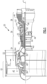
Figure 1 schematically illustrates a gas turbine engine embodiment. -
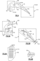
Figure 2A is a perspective view of the airfoil having the disclosed cooling passage. -
Figure 2B is a plan view of the airfoil illustrating directional references. -
Figure 3 is a schematic view of one example cooling passage including three cooling passageways. -
Figure 4 is a cross-sectional view of the airfoil taken along line 4-4 ofFigure 2A . -
Figure 5A is an enlarged view of a leading edge portion of the airfoil shown inFigure 4 . -
Figure 5B is an enlarged view of a trailing edge portion of the airfoil shown inFigure 4 . -
Figure 6A is an elevational view of an example turbulator arrangement. -
Figure 6B is an end view of the turbulator arrangement shown inFigure 6A . - The embodiments, examples and alternatives of the preceding paragraphs, the claims, or the following description and drawings, including any of their various aspects or respective individual features, may be taken independently or in any combination. Features described in connection with one embodiment are applicable to all embodiments, unless such features are incompatible.
-
Figure 1 schematically illustrates agas turbine engine 20. Thegas turbine engine 20 is disclosed herein as a two-spool turbofan that generally incorporates afan section 22, acompressor section 24, acombustor section 26 and aturbine section 28. Alternative engines might include an augmentor section (not shown) among other systems or features. Thefan section 22 drives air along a bypass flowpath B while thecompressor section 24 drives air along a core flowpath C for compression and communication into thecombustor section 26 then expansion through theturbine section 28. Although depicted as a two-spool turbofan gas turbine engine in the disclosed non-limiting embodiment, it should be understood that the concepts described herein are not limited to use with two-spool turbofans as the teachings may be applied to other types of turbine engines including three-spool architectures. - The
exemplary engine 20 generally includes alow speed spool 30 and ahigh speed spool 32 mounted for rotation about an engine central longitudinal axis X relative to an enginestatic structure 36 viaseveral bearing systems 38. It should be understood that various bearingsystems 38 at various locations may alternatively or additionally be provided, and the location of bearingsystems 38 may be varied as appropriate to the application. - The
low speed spool 30 generally includes aninner shaft 40 that interconnects afan 42, alow pressure compressor 44 and alow pressure turbine 46. Theinner shaft 40 is connected to thefan 42 through a speed change mechanism, which in exemplarygas turbine engine 20 is illustrated as a gearedarchitecture 48 to drive thefan 42 at a lower speed than thelow speed spool 30. Thehigh speed spool 32 includes anouter shaft 50 that interconnects ahigh pressure compressor 52 andhigh pressure turbine 54. Acombustor 56 is arranged inexemplary gas turbine 20 between thehigh pressure compressor 52 and thehigh pressure turbine 54. Amid-turbine frame 57 of the enginestatic structure 36 is arranged generally between thehigh pressure turbine 54 and thelow pressure turbine 46. Themid-turbine frame 57 supports one ormore bearing systems 38 in theturbine section 28. Theinner shaft 40 and theouter shaft 50 are concentric and rotate via bearingsystems 38 about the engine central longitudinal axis X, which is collinear with their longitudinal axes. - The core airflow C is compressed by the
low pressure compressor 44 then thehigh pressure compressor 52, mixed and burned with fuel in thecombustor 56, then expanded over thehigh pressure turbine 54 andlow pressure turbine 46. Themid-turbine frame 57 includesairfoils 59 which are in the core airflow path. Theturbines low speed spool 30 andhigh speed spool 32 in response to the expansion. It will be appreciated that each of the positions of thefan section 22,compressor section 24,combustor section 26,turbine section 28, and fandrive gear system 48 may be varied. For example,gear system 48 may be located aft ofcombustor section 26 or even aft ofturbine section 28, andfan section 22 may be positioned forward or aft of the location ofgear system 48. - The
engine 20 in one example a high-bypass geared aircraft engine. In a further example, theengine 20 bypass ratio is greater than about six (6), with an example embodiment being greater than ten (10). The example speed reduction device is a gearedarchitecture 48 however other speed reducing devices such as fluid or electromechanical devices are also within the contemplation of this disclosure. The example gearedarchitecture 48 is an epicyclic gear train, such as a star gear system or other gear system, with a gear reduction ratio of greater than about 2.3, or more specifically, a ratio of from about 2.2 to about 4.0. In one disclosed embodiment, theengine 20 bypass ratio is greater than about ten (10:1), the fan diameter is significantly larger than that of thelow pressure compressor 44, and thelow pressure turbine 46 has a pressure ratio that is greater than about 5:1.Low pressure turbine 46 pressure ratio is pressure measured prior to inlet oflow pressure turbine 46 as related to the pressure at the outlet of thelow pressure turbine 46 prior to an exhaust nozzle. It should be understood, however, that the above parameters are only exemplary of one embodiment of a geared architecture engine and that the present invention is applicable to other gas turbine engines including direct drive turbofans. - A significant amount of thrust is provided by the bypass flow B due to the high bypass ratio. The
fan section 22 of theengine 20 is designed for a particular flight condition -- typically cruise at about 0.8 Mach and about 35,000 feet. The flight condition of 0.8 Mach and 35,000 ft, with the engine at its best fuel consumption - also known as bucket cruise Thrust Specific Fuel Consumption ("TSFC"). TSFC is the industry standard parameter of lbm of fuel being burned divided by lbf of thrust the engine produces at that minimum point. "Low fan pressure ratio" is the pressure ratio across the fan blade alone, without a Fan Exit Guide Vane ("FEGV") system. The low fan pressure ratio as disclosed herein according to one non-limiting embodiment is less than about 1.45. "Low corrected fan tip speed" is the actual fan tip speed in ft/sec divided by an industry standard temperature correction of [(Tambient °R) / 518.7 °R) 0.5]. The "low corrected fan tip speed" as disclosed herein according to one non-limiting embodiment is less than about 1150 ft / second. - The disclosed cooling passage may be used in various gas turbine engine components, such as those subject to creep due to high temperature and stress. For exemplary purposes, a
turbine blade 64 is described. It should be understood that the cooling passage may also be used in vanes, blade outer air seals, and turbine platforms, combustor liners, and exhaust liners, for example. Turbine blades are subject to particularly high stress due to high centrifugal loads in the radial direction. - Referring to
Figures 2A and 2B , aroot 74 of eachturbine blade 64 is mounted to the rotor disk. Theturbine blade 64 includes aplatform 76, which provides the inner flow path, supported by theroot 74. Anairfoil 78 extends in a radial direction R from theplatform 76 to atip 80. It should be understood that the turbine blades may be integrally formed with the rotor such that the roots are eliminated. In such a configuration, the platform is provided by the outer diameter of the rotor. Theairfoil 78 provides leading and trailingedges tip 80 is arranged adjacent to a blade outer air seal (not shown). - The
airfoil 78 ofFigure 2B somewhat schematically illustrates an exterior airfoil surface extending in a chord-wise direction C from a leadingedge 82 to a trailingedge 84. Theairfoil 78 is provided between pressure (typically concave) and suction (typically convex)wall Multiple turbine blades 64 are arranged circumferentially in a circumferential direction A. - The
airfoil 78 includes acooling passage 90 provided between the pressure andsuction walls cooling passage 90. - In one example, the
cooling passage 90 is provided by multiple cooling passageways, such as cooling passageways 90A, 90B, 90C, as shown inFigure 3 . The first cooling passageway 90A is provided near the leadingedge 92 of theairfoil 78. The second cooling passageway 90B is a serpentine cooling passage that is arranged at an intermediate portion of theairfoil 78 and extends to the trailingedge 84 near thetip 80. The third passageway 90C is arranged in the trailing edge portion of theairfoil 78. A cooling flow F is provided to each of the first, second and third passageways 90A, 90B, 90C, typically from theroot 74, as schematically shown inFigure 2A . Thecooling passage 90 shown inFigure 3 is exemplary only and may be configured other than depicted based upon the airfoil application. - Referring to
Figures 3-5B , elongated turbulators 92 are arranged within thecooling passage 90 at various locations and may be grouped intoclusters 94 of generally parallel elongated turbulators. Turbulators, sometimes called trip strips, are used to disrupt the regular flow of cooling air on the internal passages of an airfoil, affecting an increase of convection on the intended surfaces. Theelongated turbulators 92 extend substantially in a load direction L, which typically corresponds to the radial direction R for turbine blades. - The disclosed elongated turbulators minimize the changes to the stiffness of the airfoil. The turbulators serve as a relatively cool, load bearing feature on the inside of the airfoil. In the highly creep afflicted regions of an airfoil, the inclusion of radially oriented turbulators can help decelerate the progression of the deformation. By orienting the turbulators radially, some of the load, the direction of which is largely radial in a typical airfoil, can be carried along the turbulators across the creep afflicted region, reducing the amount of stress in the region and therefore slowing the progression of creep damage. The turbulators enhance convection from the airflow to the hot surface and work to cool the creep-afflicted region.
- The
elongated turbulators 92 are discrete, generally linear structures and have an aspect ratio provided by alength 96 that is substantially greater than a width 98. The aspect ratio is at least 4:1 in one example. Theelongated turbulators 92 extend from a wall, for example, the pressure andsuction side walls height 100 that is less than awidth 102 of the cooling passage, as shown inFigures 5A and 5B . - One or more turbulators can be provided on only one wall of the airfoil or opposite walls. If they are designed into opposite walls, they may have similar or dissimilar patterns. The turbulators can vary in height along their length. They can be cast with the airfoil or joined to it after casting. They may also be manufactured using an additive technique.
- The
elongated turbulators 92 extend substantially in the same direction as the load direction L, for example, at anangle 104 of up to +/- 15° relative to the load direction L. In cooling passages having tortuous passageway, such as the second cooling passageway 90B, theelongated turbulators 92 are substantially within astraight portion 105 and outside of abend 106. Thebend 106 is defined as the portion of the passageway perpendicular to anend 108 of apartition wall 109 providing the generallystraight portion 105. The term "substantially within" means that greater than 50% of theelongated turbulators 92 are within the substantiallystraight portion 105. - It may be desirable to arrange the
elongated turbulators 92 in a trailingedge portion 112, which is provided on the aft third of the airfoil in the chord-wise direction C. The trailingedge portion 112 may be particularly susceptible to stress since the airfoil is much thinner in this area. - In the example shown in
Figures 6A and 6B , theelongated turbulators 192 may also include asecondary turbulators 110 interconnecting adjacentelongated turbulators 192. In one example, the secondary turbulators 110 and theelongated turbulators 192 are arranged in a cross-hatched pattern. Thesecondary turbulators 110 extend a height from thewall 186 that is less than the height of theelongated turbulators 192 in the example shown. - It should also be understood that although a particular component arrangement is disclosed in the illustrated embodiment, other arrangements will benefit herefrom. Although particular step sequences are shown, described, and claimed, it should be understood that steps may be performed in any order, separated or combined unless otherwise indicated and will still benefit from the present invention.
- Although the different examples have specific components shown in the illustrations, embodiments of this invention are not limited to those particular combinations. It is possible to use some of the components or features from one of the examples in combination with features or components from another one of the examples.
- Although example embodiments have been disclosed, a worker of ordinary skill in this art would recognize that certain modifications would come within the scope of the claims. For that and other reasons, the following claims should be studied to determine their true scope and content.
Claims (9)
- A gas turbine engine component (64) comprising:spaced apart walls (86, 88) extending in a load direction and providing a cooling passage (90), the cooling passage (90) providing a tortuous passage having a generally straight portion (105) extending in the load direction and a bend (106) transverse to the load direction; andelongated turbulators (92; 192) protruding from at least one of the walls (86, 88) and extending substantially in the load direction, the elongated turbulators (92; 192) substantially within the generally straight portion (105).
- A gas turbine engine component (64) comprising:spaced apart walls (86, 88) extending in a load direction and providing a cooling passage (90); anda cluster (94) of elongated turbulators (92; 192) protruding from at least one wall (86, 88) and extending substantially in the load direction, the turbulators (92; 192) parallel to one another.
- A gas turbine engine component (64) comprising:spaced apart walls (86, 88) extending in a load direction and providing a cooling passage (90); andelongated turbulators (192) protruding from at least one wall (86, 88) and extending substantially in the load direction, and a secondary turbulator (110) arranged transverse to and intersecting the elongated turbulators (92).
- The gas turbine engine component according to any preceding claim, wherein the component (64) is a turbine blade, the spaced apart walls (86, 88) provide an airfoil (78), and the load direction is a radial direction.
- The gas turbine engine component according to claim 4, wherein the elongated turbulators (92; 192) are arrange on both walls (86, 88).
- The gas turbine engine component according to claim 4 or 5, wherein the walls (86, 88) are spaced apart a width, and the elongated turbulators (92; 192) have a height less than the width.
- The gas turbine engine component according to any of claims 4 to 6, wherein the elongated turbulators (92; 192) extend in the radial direction a length and include a width, a ratio of the length to the width being at least 4:1.
- The gas turbine engine component according to any of claims 4 to 7, wherein the airfoil (78) includes a trailing edge portion (84), the elongated turbulators (92) arranged in the trailing edge portion (84).
- The gas turbine engine component according to any of claims 4 to 8, wherein the elongated turbulators (92; 192) are oriented at an angle relative to the radial direction within +/- 15°.
Applications Claiming Priority (3)
| Application Number | Priority Date | Filing Date | Title |
|---|---|---|---|
| US201361873942P | 2013-09-05 | 2013-09-05 | |
| EP14862682.3A EP3042041B1 (en) | 2013-09-05 | 2014-08-27 | Gas turbine engine airfoil turbulator for airfoil creep resistance |
| PCT/US2014/052850 WO2015073092A2 (en) | 2013-09-05 | 2014-08-27 | Gas turbine engine airfoil turbulator for airfoil creep resistance |
Related Parent Applications (1)
| Application Number | Title | Priority Date | Filing Date |
|---|---|---|---|
| EP14862682.3A Division EP3042041B1 (en) | 2013-09-05 | 2014-08-27 | Gas turbine engine airfoil turbulator for airfoil creep resistance |
Publications (2)
| Publication Number | Publication Date |
|---|---|
| EP4397841A2 true EP4397841A2 (en) | 2024-07-10 |
| EP4397841A3 EP4397841A3 (en) | 2024-07-31 |
Family
ID=53058227
Family Applications (2)
| Application Number | Title | Priority Date | Filing Date |
|---|---|---|---|
| EP24178070.9A Withdrawn EP4397841A3 (en) | 2013-09-05 | 2014-08-27 | Gas turbine engine airfoil turbulator for airfoil creep resistance |
| EP14862682.3A Active EP3042041B1 (en) | 2013-09-05 | 2014-08-27 | Gas turbine engine airfoil turbulator for airfoil creep resistance |
Family Applications After (1)
| Application Number | Title | Priority Date | Filing Date |
|---|---|---|---|
| EP14862682.3A Active EP3042041B1 (en) | 2013-09-05 | 2014-08-27 | Gas turbine engine airfoil turbulator for airfoil creep resistance |
Country Status (3)
| Country | Link |
|---|---|
| US (1) | US20160208620A1 (en) |
| EP (2) | EP4397841A3 (en) |
| WO (1) | WO2015073092A2 (en) |
Families Citing this family (8)
| Publication number | Priority date | Publication date | Assignee | Title |
|---|---|---|---|---|
| US10364683B2 (en) | 2013-11-25 | 2019-07-30 | United Technologies Corporation | Gas turbine engine component cooling passage turbulator |
| JP2017089601A (en) * | 2015-11-17 | 2017-05-25 | 株式会社東芝 | Cooling structure and gas turbine |
| US10260354B2 (en) | 2016-02-12 | 2019-04-16 | General Electric Company | Airfoil trailing edge cooling |
| EP3645838B1 (en) * | 2017-06-30 | 2022-06-01 | Siemens Energy Global GmbH & Co. KG | Turbine airfoil with trailing edge features and casting core |
| GB2581351A (en) * | 2019-02-13 | 2020-08-19 | Rolls Royce Plc | Blade for a gas turbine engine |
| FR3094032B1 (en) * | 2019-03-22 | 2021-05-21 | Safran Aircraft Engines | AIRCRAFT TURBOMACHINE BLADE AND ITS MANUFACTURING PROCESS BY LOST WAX MOLDING |
| GB202111579D0 (en) * | 2021-08-12 | 2021-09-29 | Rolls Royce Plc | Blade intake |
| DE102024202241A1 (en) * | 2024-03-11 | 2025-09-11 | Siemens Energy Global GmbH & Co. KG | vane |
Family Cites Families (11)
| Publication number | Priority date | Publication date | Assignee | Title |
|---|---|---|---|---|
| US5232343A (en) * | 1984-05-24 | 1993-08-03 | General Electric Company | Turbine blade |
| US5468125A (en) | 1994-12-20 | 1995-11-21 | Alliedsignal Inc. | Turbine blade with improved heat transfer surface |
| JP4489336B2 (en) * | 1999-06-28 | 2010-06-23 | シーメンス アクチエンゲゼルシヤフト | Structural parts that receive hot gases |
| US6672836B2 (en) * | 2001-12-11 | 2004-01-06 | United Technologies Corporation | Coolable rotor blade for an industrial gas turbine engine |
| US7186084B2 (en) * | 2003-11-19 | 2007-03-06 | General Electric Company | Hot gas path component with mesh and dimpled cooling |
| US7094031B2 (en) * | 2004-09-09 | 2006-08-22 | General Electric Company | Offset Coriolis turbulator blade |
| US7189060B2 (en) * | 2005-01-07 | 2007-03-13 | Siemens Power Generation, Inc. | Cooling system including mini channels within a turbine blade of a turbine engine |
| US7163373B2 (en) * | 2005-02-02 | 2007-01-16 | Siemens Power Generation, Inc. | Vortex dissipation device for a cooling system within a turbine blade of a turbine engine |
| US7377747B2 (en) * | 2005-06-06 | 2008-05-27 | General Electric Company | Turbine airfoil with integrated impingement and serpentine cooling circuit |
| US8167560B2 (en) * | 2009-03-03 | 2012-05-01 | Siemens Energy, Inc. | Turbine airfoil with an internal cooling system having enhanced vortex forming turbulators |
| EP2584145A1 (en) * | 2011-10-20 | 2013-04-24 | Siemens Aktiengesellschaft | A cooled turbine guide vane or blade for a turbomachine |
-
2014
- 2014-08-27 EP EP24178070.9A patent/EP4397841A3/en not_active Withdrawn
- 2014-08-27 US US14/915,455 patent/US20160208620A1/en not_active Abandoned
- 2014-08-27 WO PCT/US2014/052850 patent/WO2015073092A2/en not_active Ceased
- 2014-08-27 EP EP14862682.3A patent/EP3042041B1/en active Active
Also Published As
| Publication number | Publication date |
|---|---|
| EP3042041A4 (en) | 2016-09-28 |
| EP4397841A3 (en) | 2024-07-31 |
| EP3042041A2 (en) | 2016-07-13 |
| US20160208620A1 (en) | 2016-07-21 |
| WO2015073092A3 (en) | 2015-08-06 |
| WO2015073092A2 (en) | 2015-05-21 |
| EP3042041B1 (en) | 2024-05-29 |
Similar Documents
| Publication | Publication Date | Title |
|---|---|---|
| EP3009599A1 (en) | Gas turbine engine component with film cooling hole feature | |
| EP2975217A1 (en) | Using inserts to balance heat transfer and stress in high temperature alloys | |
| EP3042041B1 (en) | Gas turbine engine airfoil turbulator for airfoil creep resistance | |
| EP2942488B1 (en) | Blade for a gas turbine engine, gas turbine engine and method of cooling a blade for a gas turbine engine | |
| EP2993304B1 (en) | Gas turbine engine component with film cooling hole | |
| EP2952683A1 (en) | Gas turbine engine airfoil with large thickness properties | |
| EP3118414A1 (en) | Gas turbine engine airfoil | |
| WO2014105392A1 (en) | Gas turbine engine serpentine cooling passage with chevrons | |
| EP3461993B1 (en) | Gas turbine engine blade | |
| EP3009600A1 (en) | Gas turbine engine turbine blade with cooled tip | |
| US20140219813A1 (en) | Gas turbine engine serpentine cooling passage | |
| EP3112596A1 (en) | Gas turbine engine airfoil with bi-axial skin cooling passage and corresponding gas turbine engine | |
| EP2971544B1 (en) | Gas turbine engine component cooling with interleaved facing trip strips | |
| EP2932043B1 (en) | Gas turbine engine turbine blade leading edge tip trench cooling | |
| EP3467260B1 (en) | Turbine blade with bowed tip | |
| EP3047107B1 (en) | Gas turbine engine component platform seal cooling | |
| EP3059391A1 (en) | Gas turbine engine turbine blade cooling using upstream stator vane | |
| EP2938831B1 (en) | Gas turbine engine turbine blade tip cooling | |
| EP2961964B1 (en) | Gas turbine engine component and corresponding method of manufacturing an aperture | |
| EP3470627B1 (en) | Gas turbine engine airfoil | |
| EP3477055B1 (en) | Component for a gas turbine engine comprising an airfoil |
Legal Events
| Date | Code | Title | Description |
|---|---|---|---|
| PUAI | Public reference made under article 153(3) epc to a published international application that has entered the european phase |
Free format text: ORIGINAL CODE: 0009012 |
|
| STAA | Information on the status of an ep patent application or granted ep patent |
Free format text: STATUS: THE APPLICATION HAS BEEN PUBLISHED |
|
| PUAL | Search report despatched |
Free format text: ORIGINAL CODE: 0009013 |
|
| AC | Divisional application: reference to earlier application |
Ref document number: 3042041 Country of ref document: EP Kind code of ref document: P |
|
| AK | Designated contracting states |
Kind code of ref document: A2 Designated state(s): AL AT BE BG CH CY CZ DE DK EE ES FI FR GB GR HR HU IE IS IT LI LT LU LV MC MK MT NL NO PL PT RO RS SE SI SK SM TR |
|
| AK | Designated contracting states |
Kind code of ref document: A3 Designated state(s): AL AT BE BG CH CY CZ DE DK EE ES FI FR GB GR HR HU IE IS IT LI LT LU LV MC MK MT NL NO PL PT RO RS SE SI SK SM TR |
|
| RIC1 | Information provided on ipc code assigned before grant |
Ipc: F01D 5/18 20060101AFI20240624BHEP |
|
| STAA | Information on the status of an ep patent application or granted ep patent |
Free format text: STATUS: REQUEST FOR EXAMINATION WAS MADE |
|
| 17P | Request for examination filed |
Effective date: 20250129 |
|
| STAA | Information on the status of an ep patent application or granted ep patent |
Free format text: STATUS: THE APPLICATION IS DEEMED TO BE WITHDRAWN |
|
| 18D | Application deemed to be withdrawn |
Effective date: 20250201 |