EP4397812A1 - Work machine - Google Patents
Work machine Download PDFInfo
- Publication number
- EP4397812A1 EP4397812A1 EP22886510.1A EP22886510A EP4397812A1 EP 4397812 A1 EP4397812 A1 EP 4397812A1 EP 22886510 A EP22886510 A EP 22886510A EP 4397812 A1 EP4397812 A1 EP 4397812A1
- Authority
- EP
- European Patent Office
- Prior art keywords
- movement
- area change
- work
- motion
- start position
- Prior art date
- Legal status (The legal status is an assumption and is not a legal conclusion. Google has not performed a legal analysis and makes no representation as to the accuracy of the status listed.)
- Pending
Links
- 230000033001 locomotion Effects 0.000 claims abstract description 474
- 238000009412 basement excavation Methods 0.000 claims description 76
- 239000004576 sand Substances 0.000 claims description 35
- 239000002689 soil Substances 0.000 claims description 18
- 238000007599 discharging Methods 0.000 claims description 8
- 238000011144 upstream manufacturing Methods 0.000 claims description 8
- 238000007790 scraping Methods 0.000 claims description 6
- 238000003384 imaging method Methods 0.000 description 9
- 230000000694 effects Effects 0.000 description 6
- 230000008602 contraction Effects 0.000 description 4
- 238000001514 detection method Methods 0.000 description 4
- 230000001133 acceleration Effects 0.000 description 3
- 238000000034 method Methods 0.000 description 3
- 230000004048 modification Effects 0.000 description 3
- 238000012986 modification Methods 0.000 description 3
- 230000002452 interceptive effect Effects 0.000 description 2
- 238000010586 diagram Methods 0.000 description 1
- 239000002440 industrial waste Substances 0.000 description 1
- 230000000452 restraining effect Effects 0.000 description 1
- 230000000630 rising effect Effects 0.000 description 1
- 239000004575 stone Substances 0.000 description 1
- 239000002699 waste material Substances 0.000 description 1
Images









Classifications
-
- E—FIXED CONSTRUCTIONS
- E02—HYDRAULIC ENGINEERING; FOUNDATIONS; SOIL SHIFTING
- E02F—DREDGING; SOIL-SHIFTING
- E02F9/00—Component parts of dredgers or soil-shifting machines, not restricted to one of the kinds covered by groups E02F3/00 - E02F7/00
- E02F9/26—Indicating devices
-
- E—FIXED CONSTRUCTIONS
- E02—HYDRAULIC ENGINEERING; FOUNDATIONS; SOIL SHIFTING
- E02F—DREDGING; SOIL-SHIFTING
- E02F3/00—Dredgers; Soil-shifting machines
- E02F3/04—Dredgers; Soil-shifting machines mechanically-driven
- E02F3/28—Dredgers; Soil-shifting machines mechanically-driven with digging tools mounted on a dipper- or bucket-arm, i.e. there is either one arm or a pair of arms, e.g. dippers, buckets
- E02F3/36—Component parts
- E02F3/42—Drives for dippers, buckets, dipper-arms or bucket-arms
- E02F3/43—Control of dipper or bucket position; Control of sequence of drive operations
- E02F3/435—Control of dipper or bucket position; Control of sequence of drive operations for dipper-arms, backhoes or the like
- E02F3/437—Control of dipper or bucket position; Control of sequence of drive operations for dipper-arms, backhoes or the like providing automatic sequences of movements, e.g. linear excavation, keeping dipper angle constant
-
- E—FIXED CONSTRUCTIONS
- E02—HYDRAULIC ENGINEERING; FOUNDATIONS; SOIL SHIFTING
- E02F—DREDGING; SOIL-SHIFTING
- E02F3/00—Dredgers; Soil-shifting machines
- E02F3/04—Dredgers; Soil-shifting machines mechanically-driven
- E02F3/28—Dredgers; Soil-shifting machines mechanically-driven with digging tools mounted on a dipper- or bucket-arm, i.e. there is either one arm or a pair of arms, e.g. dippers, buckets
- E02F3/36—Component parts
- E02F3/42—Drives for dippers, buckets, dipper-arms or bucket-arms
- E02F3/43—Control of dipper or bucket position; Control of sequence of drive operations
-
- E—FIXED CONSTRUCTIONS
- E02—HYDRAULIC ENGINEERING; FOUNDATIONS; SOIL SHIFTING
- E02F—DREDGING; SOIL-SHIFTING
- E02F9/00—Component parts of dredgers or soil-shifting machines, not restricted to one of the kinds covered by groups E02F3/00 - E02F7/00
- E02F9/20—Drives; Control devices
-
- E—FIXED CONSTRUCTIONS
- E02—HYDRAULIC ENGINEERING; FOUNDATIONS; SOIL SHIFTING
- E02F—DREDGING; SOIL-SHIFTING
- E02F9/00—Component parts of dredgers or soil-shifting machines, not restricted to one of the kinds covered by groups E02F3/00 - E02F7/00
- E02F9/20—Drives; Control devices
- E02F9/22—Hydraulic or pneumatic drives
-
- E—FIXED CONSTRUCTIONS
- E02—HYDRAULIC ENGINEERING; FOUNDATIONS; SOIL SHIFTING
- E02F—DREDGING; SOIL-SHIFTING
- E02F9/00—Component parts of dredgers or soil-shifting machines, not restricted to one of the kinds covered by groups E02F3/00 - E02F7/00
- E02F9/26—Indicating devices
- E02F9/261—Surveying the work-site to be treated
- E02F9/262—Surveying the work-site to be treated with follow-up actions to control the work tool, e.g. controller
-
- E—FIXED CONSTRUCTIONS
- E02—HYDRAULIC ENGINEERING; FOUNDATIONS; SOIL SHIFTING
- E02F—DREDGING; SOIL-SHIFTING
- E02F9/00—Component parts of dredgers or soil-shifting machines, not restricted to one of the kinds covered by groups E02F3/00 - E02F7/00
- E02F9/26—Indicating devices
- E02F9/264—Sensors and their calibration for indicating the position of the work tool
- E02F9/265—Sensors and their calibration for indicating the position of the work tool with follow-up actions (e.g. control signals sent to actuate the work tool)
Definitions
- the present invention relates to a work machine capable of being automatically operated.
- Patent Literature 1 discloses an automatically-operated excavator by which work motions from excavation of earth and sand to removal thereof are automatically performed. Specifically, Patent Literature 1 discloses automatically shifting the next excavation position in the turning direction of an upper turning body when the excavation depth reaches a set value at a certain excavation position.
- Patent Literature 1 Japanese Unexamined Patent Publication No. 2001-123479
- FIG. 1 shows a work machine 1 according to a first embodiment of the present invention.
- the work machine 1 is capable of being automatically operated.
- the work machine 1 is a hydraulic excavator, including a machine body 25 including a lower traveling body 21 and an upper turning body 22, a turning device 24, an attachment 30, and a work driving device 40.
- the lower traveling body 21 includes a pair of crawler, which is actuated to thereby enable the lower traveling body 21 to perform a traveling motion.
- the upper turning body 22 is mounted on the lower traveling body 21 capably of performing a turning motion of turning with respect to the lower traveling body 21.
- the turning device 24 is a turning driving device that causes the upper turning body 22 to perform the turning motion.
- the upper turning body 22 includes a cab (operation room) 23 which forms a front part of the upper turning body 22.
- the attachment 30 is a work device attached to the upper turning body 22 capably of performing a work motion.
- the work motion is a motion for processing an object, including a vertically rotational movement.
- the attachment 30 includes a boom 31, an arm 32, and a bucket 33.
- the boom 31 has a proximal end and a distal end opposite thereto, the proximal end being connected to the upper turning body 22 capably of vertically rotational movement (capably of being raised and lowered).
- the arm 32 has a proximal end and a distal end opposite thereto, the proximal end being connected to the distal end of the boom 31 capably of vertically rotational movement.
- the bucket 33 is a tip attachment, which is attached to the distal end of the arm 32 capably of rotational movement in a front-rear direction to form the tip of the attachment 30.
- the bucket 33 has a shape capable of performing work operation such as excavation, leveling, scooping, and the like, on an excavation object including earth and sand.
- the excavation object by the bucket 33 is not limited to earth and sand but allowed to be also a stone or a waste (industrial waste, etc.).
- the work machine according to the present invention is not limited to an excavation machine and, therefore, the work object is not limited to the excavation object.
- the tip attachment to form the tip of the work apparatus is not limited to the bucket 33 for holding earth and sand as described above but allowed to be also a grapple for gripping a work object, a lifting magnet for attracting a work object to hold it, or the like.
- the work drive device 40 is capable of making the attachment 30 perform the work motion by hydraulic actuation of the attachment 30.
- the work drive device 40 includes a plurality of hydraulic cylinders, each of which is capable of performing expansion and contraction motions, the plurality of hydraulic cylinders including a boom cylinder 41, an arm cylinder 42, and a bucket cylinder 43.
- the boom cylinder 41 is arranged so as to actuate the boom 31 vertically rotationally in rising and falling directions (vertical direction) with respect to the upper turning body 22 by performing the expansion and contraction motions.
- the boom cylinder 41 has a proximal end to be rotatably connected to the upper turning body 22 and a distal end to be rotatably connected to the boom 31.
- the arm cylinder 42 is arranged so as to actuate the arm 32 vertically rotationally with respect to the boom 31 by performing the expansion and contraction motions.
- the arm cylinder 42 has a proximal end to be rotationally connected to the boom 31 and a distal end to be rotationally connected to the arm 32.
- the working posture detector 60 detects a working posture, which is the posture of the attachment 30 as the work device, including a boom inclination sensor 61, an arm inclination sensor 62, and a bucket inclination sensor 63 in the present embodiment.
- the turning posture information is information detected by the turning angle sensor 52, that is, information about the turning angle (turning posture) of the upper turning body 22 with respect to the lower traveling body 21.
- the working posture information is information about the posture detected by the working posture detector 60, that is, the posture of the attachment 30 as the work device.
- the working posture information contains: information detected by the boom inclination sensor 61, that is, information on the posture of the boom 31; information detected by the arm inclination sensor 62, that is, information on the posture of the arm 32; and information detected by the bucket inclination sensor 63, that is, information on the posture of the bucket 33.
- the control unit 11 makes the upper turning body 22 and the attachment 30 perform the series of motions a plurality of times.
- the control unit 11 according to the present embodiment makes the series of motions repeated with a change of the height of the tip of the bucket 33 during the excavation motion.
- the series of motions from excavation of earth and sand to earth removal are thereby repeated at the same excavation place with the change of the depth of excavation of earth and sand.
- control unit 11 or the storage device 13 stores a target number of repetitions that is the number of times by which the series of motions is to be repeated and the control unit 11 is configured to judge that the work by the repetition of the series of motions has reached a predetermined stage at the time when the number of times by which the series of motions are repeated reaches the target number of repetitions.
- the control unit 11 serves as a start position shifting means of shifting the start point of the excavation motion in the next series of motions in the turning direction of the upper turning body 22 from the point A. Specifically, the start position is shifted in the turning direction from the point A by means of turning the upper turning body 22. The start position is shifted to the position separated from the point A by a predetermined angle in a direction of separating from the point D in the turning direction (the reverse direction to that of the lifting and turning motion, i.e., the rightward direction in FIG. 3 ). Along with the shift of the start point from the point A, the terminal point of the excavation motion is also shifted from the point B by the same angle in the same direction.
- the control unit 11 serves as a lower-traveling-body moving means of making the lower traveling body 21 perform the traveling motion to thereby move the lower traveling body 21 in the traveling direction when the work by the repetition of the series of motions reaches a predetermined stage in a state where the start position has reached the shift limiting surface 75, that is, when the excavation depth in the shift limiting surface 75 reaches the depth limit.
- the movement of the lower traveling body 21 is the area change movement for changing the area of the processing work by the series of motions.
- control unit 11 sets the start position of the excavation motion after the area change movement, namely, the after-movement start position, so as to make the processing work by the series of motions started immediately after the area change movement continued with the processing work by the series of motions immediately before the area change movement.
- the movement direction which is the direction of the area change movement of the lower traveling body 21 is rightward in FIG. 3 , being the same direction as the direction in which the start position of the series of motions is shifted before the area change movement, that is, the same direction as the direction in which the area of the repeated series of motions is gradually shifted.
- the shift limiting surface 75 is set to a surface passing through the position of the tip of the bucket 33 in a state where the upper turning body 22 has been turned in a direction of separating from the point D, i.e., in a direction reverse to the direction of the lifting and turning motion, by a preset limit angle ⁇ from a posture where the tip of the bucket 33 is located at the start position of the first excavation motion.
- the surface passing through the start position that has been shifted by a preset allowable number of shift times may be set to the shift limiting surface 75.
- the control unit 11 is preferably configured to, for example, as shown in FIG.
- the earth removal position between the point C and the point D shown in FIG. 3 and FIGS. 6 to 8 i.e., the position to which the earth and sand excavated by the bucket 33 is to be discharged, is outside the working area 80.
- the earth and sand excavated by the bucket 33 may be discharged to the earth removal position in the working area 80.
- the control unit 11 sets the start position of the excavation motion immediately after the area change movement, namely, the after-movement start position, so as to allow the earth and sand discharged to the earth removal position before the area change movement to be excavated by the excavation motion after the area change movement.
- the movement direction of the area change movement is the leftward direction in FIG.
- the control unit 11 judges whether or not the amount of soil at the earth removal position is equal to or more than a predetermined amount (YES in step S6), and only when judging the amount of soil at the earth removal position to be equal to or more than the predetermined amount (YES in step S6), the control unit 11 moves the shift limiting surface 75 in a direction reverse to the movement direction of the lower traveling body 21 (step S7).
- the control unit 11 judges whether or not the start position of the excavation motion gradually changed in the above-described manner has reached the shift limiting surface 75 (step S8). If judging that the start position has not yet reached the shift limiting surface 75 (NO in step S8), the control unit 11 makes the upper turning body 22 turned by a predetermined turning angle to thereby shift the start position of the excavation motion in the turning direction of the upper turning body 22 (Step S9). The series of motions is thereby repeated in an new excavation place.
- FIGS. 12 to 14 Next will be described a second embodiment of the present invention with reference to FIGS. 12 to 14 .
- the configuration common to the first embodiment and the effect exhibited thereby will be omitted, and the points different from the first embodiment will be mainly described.
- the same member as the first embodiment has the same sign as that of the first embodiment.
- FIGS. 12 and 13 show a posture change angle ⁇ c in each case, and the after-movement posture is set to a posture where the upper turning body 22 has been turned in the direction reverse to the movement direction (leftward direction in FIG. 12 ) with respect to the lower traveling body 21 by the posture change angle ⁇ c from the turning posture immediately before the area change movement.
- the control of turning the upper turning body 22 by the posture changing angle ⁇ c after the area change movement is performed, and the start position is determined in the posture of the upper turning body 22 after the turning.
- the turning posture of the upper turning body 22 is changed by a predetermined turning angle each time the work by the repetition of the series of motions reaches a predetermined stage.
- the setting of the after-movement posture setting enables the processing work by the series of motions after the area change movement to be suitably continued with the processing work before the area change movement.
- the control unit 11 serves as a movement limit setting means of setting a movement limiting position 88 of the lower traveling body 21.
- the movement limiting position 88 is set to such a position that the processing work after the area change movement of the lower traveling body 21 stopped at the movement limiting position 88 is continued with the processing work before the area change movement. More specifically, the movement limiting position 88 is set so as to render the start position of the excavation motion in the first series of motions in a state where the area change movement of the lower traveling body 21 is stopped at the movement limiting position 88, namely, the after-movement start position (point A1), a position on the shift limiting surface 75.
- the control unit 11 serves as a lower-traveling-body moving means of making the lower traveling body 21 perform the area change movement and stopping the area change movement at the time when the lower traveling body 21 reaches the movement limiting position 88.
- Such control of the area change movement enables the processing work after the area change movement to be suitably continued with the processing work before the area change movement.
- the movement limiting position 88 may be set based on a work plan. For example, setting the movement limiting position 88 on the boundary of the area in which the work is planned allows work to be restrained from deviating from the work plan.
- the movement limiting position 88 alternatively, may be set based on the position of an obstacle or the like imaged by the imaging device 26. Setting the movement limiting position 88 on the front side of the position of the obstacle or the like prevents the attachment 30 from interfering with the obstacle or the like.
- the after-movement start position (point A1), which is the start position of the excavation motion after the area change movement, may be deviated beyond the shift limiting surface 75 in the movement direction, for example, as shown in FIG. 14 .
- the controller is configured to perform setting the after-movement posture to the same posture as the initial posture and setting a distance of the area change movement so as to make the processing work after the area change movement continued with the processing work before the area change movement.
- the thus set movement distance enables the processing work by the series of motions after the area change movement to be suitably continued with the processing work before the area change movement, in spite of the return of the posture of the upper turning body after the area change movement (after-movement posture) to the same posture as the initial posture.
- the controller is configured to move the lower traveling body in a direction reverse to a movement direction of the area change movement when the after-movement start position is deviated beyond the shift limiting surface by the area change movement.
- the reverse movement of the lower traveling body allows the after-movement start position deviated beyond the shift limiting surface to be corrected in a direction of approaching the shift limiting surface, thereby effectively reducing the non-working area, i.e., the area where neither the processing work before the area change movement nor the processing work after the area change movement is performed.
- the controller is configured to set the after-movement start position to a position upstream of the shift limiting surface in the movement direction. This makes it possible to prevent a non-working area (area in which neither the processing work before the area change movement nor the processing work after the area change movement is performed) from being caused by the start of the processing motion at a position deviated beyond the shift limiting surface (downstream position) after the area change movement.
- the controller is configured to make the upper turning body and the work device repeat the series of motions with a change of a height of a tip of the work device in the processing motion.
- the area change movement of the lower traveling body enables excavation work to be performed over a large area.
Landscapes
- Engineering & Computer Science (AREA)
- Mining & Mineral Resources (AREA)
- Civil Engineering (AREA)
- General Engineering & Computer Science (AREA)
- Structural Engineering (AREA)
- Mechanical Engineering (AREA)
- Life Sciences & Earth Sciences (AREA)
- General Life Sciences & Earth Sciences (AREA)
- Paleontology (AREA)
- Operation Control Of Excavators (AREA)
Abstract
Description
- The present invention relates to a work machine capable of being automatically operated.
-
Patent Literature 1 discloses an automatically-operated excavator by which work motions from excavation of earth and sand to removal thereof are automatically performed. Specifically,Patent Literature 1 discloses automatically shifting the next excavation position in the turning direction of an upper turning body when the excavation depth reaches a set value at a certain excavation position. - Even with the shift of the excavation position in the turning direction of the upper turning body, however, there remains a limit in the expansion of working area. An automatically-operated excavator is desired to continue work over a larger area.
- Patent Literature 1:
Japanese Unexamined Patent Publication No. 2001-123479 - It is an object of the present invention to provide a work machine capable of continuing work by automatic operation over a large area.
- Provided is a work machine including a lower traveling body, an upper turning body, a work device, and a controller. The lower traveling body is capable of performing a traveling motion. The upper turning body is mounted on the lower traveling body capably of turning. The work device is rotatably attached to the upper turning body capably of performing a processing motion for processing an object. The controller controls driving of the upper turning body and the attachment so as to make the upper turning body and the work device perform a series of motions including the processing motion by the work device a plurality of times. The controller is configured to perform: shifting a start position of the processing motion included in the next series of motions in a turning direction of the upper turning body when work performed by the series of motions reaches a predetermined stage; making the lower traveling body perform an area change movement that is a movement for changing an area of processing work, which is work performed by the series of motions, when the processing work reaches the predetermined stage in a state where the start position has reached a predetermined shift limiting surface that defines a limit of the shift of the start position in the turning direction; and setting an after-movement start position, which is a start position of the processing motion after the area change movement, so as to make the processing work after the area change movement and the processing work before the area change movement continued with each other.
-
-
FIG. 1 is a side view of a work machine according to a first embodiment of the present invention. -
FIG. 2 is a block diagram showing a control unit installed on the work machine and elements connected thereto. -
FIG. 3 is a plan view of the work machine to show a target trajectory of a tip of a bucket in a series of motions before and after an area change movement. -
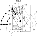
FIG. 4 is a plan view of the work machine to show a movement distance of the area change movement. -
FIG. 5 is a plan view of the work machine to show an example of setting of a shift limiting surface. -
FIG. 6 is a plan view of the work machine to show an area change movement for setting an after-movement start position upstream of the shift limiting surface with respect to a movement direction that is a direction of the area change movement. -
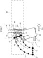
FIG. 7 is a plan view of the work machine to show an example of setting of a movement distance of the area change movement for setting the after-movement start position shown inFIG. 6 . -
FIG. 8 is a plan view of the work machine to show the movement of the shift limiting surface upstream with respect to the traveling direction of the lower traveling body. -
FIG. 9 is a plan view of the work machine to show work for moving earth and sand in the movement direction of the area change movement. -
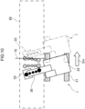
FIG. 10 is a plan view of the work machine to show work for forming a slope. -
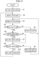
FIG. 11 is a flowchart showing a process to be performed by a controller of the work machine. -
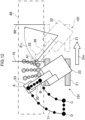
FIG. 12 is a plan view of a work machine according to a second embodiment of the present invention to show a state where the lower traveling body has performed an area change movement by a predetermined movement distance. -
FIG. 13 is a plan view of the work machine according to the second embodiment of the present invention to show a state where the lower traveling body has moved by a distance different from the movement distance. -
FIG. 14 is a plan view of the work machine according to the second embodiment of the present invention to show a state where the after-movement start position is deviated beyond the shift limiting surface by area change movement. - A preferred embodiment of the present invention will now be described with reference to the drawings.
-
FIG. 1 shows awork machine 1 according to a first embodiment of the present invention. Thework machine 1 is capable of being automatically operated. Thework machine 1 is a hydraulic excavator, including amachine body 25 including alower traveling body 21 and an upper turningbody 22, aturning device 24, anattachment 30, and awork driving device 40. - The lower traveling
body 21 includes a pair of crawler, which is actuated to thereby enable the lower travelingbody 21 to perform a traveling motion. The upper turningbody 22 is mounted on the lower travelingbody 21 capably of performing a turning motion of turning with respect to the lower travelingbody 21. Theturning device 24 is a turning driving device that causes the upper turningbody 22 to perform the turning motion. The upper turningbody 22 includes a cab (operation room) 23 which forms a front part of the upper turningbody 22. - The
attachment 30 is a work device attached to the upper turningbody 22 capably of performing a work motion. The work motion is a motion for processing an object, including a vertically rotational movement. Theattachment 30 includes aboom 31, anarm 32, and abucket 33. Theboom 31 has a proximal end and a distal end opposite thereto, the proximal end being connected to the upper turningbody 22 capably of vertically rotational movement (capably of being raised and lowered). Thearm 32 has a proximal end and a distal end opposite thereto, the proximal end being connected to the distal end of theboom 31 capably of vertically rotational movement. Thebucket 33 is a tip attachment, which is attached to the distal end of thearm 32 capably of rotational movement in a front-rear direction to form the tip of theattachment 30. Thebucket 33 has a shape capable of performing work operation such as excavation, leveling, scooping, and the like, on an excavation object including earth and sand. The excavation object by thebucket 33 is not limited to earth and sand but allowed to be also a stone or a waste (industrial waste, etc.). Besides, the work machine according to the present invention is not limited to an excavation machine and, therefore, the work object is not limited to the excavation object. For example, the tip attachment to form the tip of the work apparatus according to the present invention is not limited to thebucket 33 for holding earth and sand as described above but allowed to be also a grapple for gripping a work object, a lifting magnet for attracting a work object to hold it, or the like. - The
work drive device 40 is capable of making theattachment 30 perform the work motion by hydraulic actuation of theattachment 30. Thework drive device 40 includes a plurality of hydraulic cylinders, each of which is capable of performing expansion and contraction motions, the plurality of hydraulic cylinders including aboom cylinder 41, anarm cylinder 42, and abucket cylinder 43. - The
boom cylinder 41 is arranged so as to actuate theboom 31 vertically rotationally in rising and falling directions (vertical direction) with respect to the upper turningbody 22 by performing the expansion and contraction motions. Theboom cylinder 41 has a proximal end to be rotatably connected to the upper turningbody 22 and a distal end to be rotatably connected to theboom 31. - The
arm cylinder 42 is arranged so as to actuate thearm 32 vertically rotationally with respect to theboom 31 by performing the expansion and contraction motions. Thearm cylinder 42 has a proximal end to be rotationally connected to theboom 31 and a distal end to be rotationally connected to thearm 32. - The
bucket cylinder 43 is arranged so as to actuate thebucket 33 rotationally with respect to thearm 32 by performing the expansion and contraction motions. Thebucket cylinder 43 has a proximal end to be rotationally connected to thearm 32 and a distal end to be rotationally connected to alink member 34. Thelink member 34 is rotationally connected to thebucket 33 to interconnect thebucket cylinder 43 and thebucket 33. - The
work machine 1 further includes aturning angle sensor 52, which is a turning angle detector, and a workingposture detector 60. - The turning
angle sensor 52 detects a turning angle of the upper turningbody 22 with respect to the lowertraveling body 21. Theturning angle sensor 52 is, for example, an encoder, a resolver, or a gyro sensor. In the present embodiment, the turning angle of the upper turningbody 22 at which the frontward direction of the upper turningbody 22 coincides with the frontward direction of the lower travelingbody 21 is fixed to 0°. - The working
posture detector 60 detects a working posture, which is the posture of theattachment 30 as the work device, including aboom inclination sensor 61, anarm inclination sensor 62, and abucket inclination sensor 63 in the present embodiment. - The
boom inclination sensor 61 is attached to theboom 31 to detect the posture of theboom 31. Theboom inclination sensor 61 is, specifically, a sensor that acquires the inclination angle of theboom 31 to a horizontal line, for example, an inclination (acceleration) sensor. The workingposture detector 60 may include, instead of theboom inclination sensor 61, a rotation angle sensor that detects a rotation angle of theboom 31 around a boom foot pin, which is a support shaft of the proximal end of theboom 31, or a stroke sensor that detects a stroke of theboom cylinder 41. - The
arm inclination sensor 62 is attached to thearm 32 to detect the posture of thearm 32. Thearm inclination sensor 62 is, specifically, a sensor that acquires the inclination angle of thearm 32 to a horizontal line, for example, an inclination (acceleration) sensor. The workingposture detector 60 may include, instead of thearm inclination sensor 62, a rotation angle sensor that detects a rotation angle of thearm 32 around an arm connection pin that is a support shaft of the proximal end of thearm 32, or a stroke sensor that detects a stroke of thearm cylinder 42. - The
bucket inclination sensor 63 is attached to thelink member 34 to detect the posture of thebucket 33. Thebucket inclination sensor 63 is, specifically, a sensor that acquires the inclination angle of thebucket 33 to a horizontal line, for example, an inclination (acceleration) sensor. The workingposture detector 60 may include, instead of thebucket inclination sensor 63, a rotation angle sensor that detects a rotation angle of thebucket 33 around a bucket connection pin which is a support shaft of the proximal end of thebucket 33, or a stroke sensor that detects a stroke of thebucket cylinder 43. - The
work machine 1 further includes animaging device 26. Theimaging device 26 is attached to theupper turning body 22. Theimaging device 26, alternatively, may be located remote from thework machine 1. Theimaging device 26 according to the present embodiment is a LIDAR. If the work machine according to the present invention includes means for imaging, however, the means may be a camera, an ultrasonic sensor, a millimeter wave radar, a stereo camera, a distance image sensor, an infrared sensor, or the like. - The following description is made about the case of excavating earth and sand using the
bucket 33. - As shown in
FIG. 2 , thework machine 1 includes acontrol unit 11 and astorage device 13. - To the
control unit 11 is input turning posture information and working posture information. The turning posture information is information detected by the turningangle sensor 52, that is, information about the turning angle (turning posture) of theupper turning body 22 with respect to the lower travelingbody 21. The working posture information is information about the posture detected by the workingposture detector 60, that is, the posture of theattachment 30 as the work device. The working posture information contains: information detected by theboom inclination sensor 61, that is, information on the posture of theboom 31; information detected by thearm inclination sensor 62, that is, information on the posture of thearm 32; and information detected by thebucket inclination sensor 63, that is, information on the posture of thebucket 33. - The
control unit 11 according to the present embodiment automatically controls motions of thework machine 1. Thecontrol unit 11 serves as a control means of controlling the driving of theupper turning body 22 and theattachment 30 so as to make theupper turning body 22 and theattachment 30 perform a series of motions. Thework machine 1 is, thus, automatically operated. Specifically, thecontrol unit 11 automatically controls the driving of theupper turning body 22 by the turningdevice 24 and the driving of theattachment 30 by thework driving device 40 based on the information detected by the turningangle sensor 52 and the workingposture detector 60. In the present embodiment, the series of motions are motions for excavating earth and sand and discharging it. The series of motions, therefore, includes an excavation motion for excavating earth and sand by thebucket 33. The excavation motion is an example of a processing motion of processing an object by theattachment 30 as the work device. - The
control unit 11 makes theupper turning body 22 and theattachment 30 perform the series of motions a plurality of times. Thecontrol unit 11 according to the present embodiment makes the series of motions repeated with a change of the height of the tip of thebucket 33 during the excavation motion. The series of motions from excavation of earth and sand to earth removal are thereby repeated at the same excavation place with the change of the depth of excavation of earth and sand. - The
storage device 13, which constitutes a controller in association with thecontrol unit 11, stores the series of motions. The series of motions are set, for example, by means of teaching by an operator. The series of motions causes the tip of theattachment 30 i.e., the tip of thebucket 33, to trace a predetermined trajectory. As described later, a part of the trajectory may be corrected along with the movement of the lower travelingbody 21. -
FIG. 3 shows atarget trajectory 71 of the tip of thebucket 33 in the series of motions. The series of motions include an excavation motion, a lifting and turning motion, an earth removal motion, and a return turning motion. The excavation motion involves the movement of the tip of thebucket 33 from a point A to a point B. The lifting and turning motion involves the turn of the tip of thebucket 33 from the point B to a point C. The lifting and turning motion is performed with earth and sand held in thebucket 33. The earth removal motion involves the movement of the tip of thebucket 33 from the point C to a point D and the rotation of thebucket 33 in the opening direction during the movement, the rotation of thebucket 33 causing the earth and sand to be discharged to a vessel of a dump truck or the like. The earth removal position is located in an area from the point C to the point D. The return turning motion involves the turn of the tip of thebucket 33 in a return direction from the point D to the point A. The control target part of theattachment 30 according to the present embodiment is the tip of thebucket 30, the target trajectory of which is graphically shown. The control target part, however, is not limited to the tip of thebucket 33. - The
control unit 11 sets a depth limit. The depth limit is a limit value set for excavation depth, which is the depth by which earth and sand is excavated by thebucket 33. As described above, the series of motions from the excavation of earth and sand to the earth removal are repeated with the change of the excavation depth. - The
control unit 11 judges that the work performed by the repetition of the series of motions has reached a predetermined stage at the time when the excavation depth in the excavation motion reaches the depth limit. When judging that the work by the repetition of the series of motions has reached the predetermined stage, thecontrol unit 11 terminates the repetition of the series of motions at the same excavation place. - It is also desirable that the
control unit 11 or thestorage device 13 stores a target number of repetitions that is the number of times by which the series of motions is to be repeated and thecontrol unit 11 is configured to judge that the work by the repetition of the series of motions has reached a predetermined stage at the time when the number of times by which the series of motions are repeated reaches the target number of repetitions. - The
control unit 11 serves as a start position shifting means of shifting the start point of the excavation motion in the next series of motions in the turning direction of theupper turning body 22 from the point A. Specifically, the start position is shifted in the turning direction from the point A by means of turning theupper turning body 22. The start position is shifted to the position separated from the point A by a predetermined angle in a direction of separating from the point D in the turning direction (the reverse direction to that of the lifting and turning motion, i.e., the rightward direction inFIG. 3 ). Along with the shift of the start point from the point A, the terminal point of the excavation motion is also shifted from the point B by the same angle in the same direction. - After shifting the start position of the excavation motion from the point A to a new position, the
control unit 11 makes theupper turning body 22 and theattachment 30 perform the next series of motions. Thus is performed processing work by the next series of motions at the new excavation place. - In
FIG. 3 , the initial posture of theupper turning body 22 is indicated by a solid line. The initial posture is the posture of theupper turning body 22 corresponding to the point A, which is the start position of the excavation motion in the first series of motions, more specifically, such a posture of theupper turning body 22 with respect to the lower travelingbody 21 as to locate the tip of thebucket 33 that is the control target part at the start position, and theupper turning body 22 in the initial posture is located at such a position that the tip of thebucket 33 is separated from the earth removal position between the point C and the point D by an initial angle in the turning direction. Along with the shift of the start position of the excavation motion from the point A, the posture of theupper turning body 22 with respect to the lower traveling body 21 (turning posture) at the start of the excavation motion is also gradually changed from the initial posture. Each time the start position is thus shifted, the series of motions are started from the shifted start position. - The
control unit 11 serves as a limiting surface setting means of setting ashift limiting surface 75 shown inFIG. 3 . Theshift limiting surface 75 defines the limit of the shift of the start position in the turning direction. Theshift limiting surface 75 is a surface perpendicular to a movement direction, which is the direction of a below-described area change movement of the lower traveling body, indicated by a straight line perpendicular to the movement direction, as shown inFIG. 3 when viewed in a direction along the turning center axis of the upper turning body 22 (vertically in general). Theshift limiting surface 75 may be set in advance and stored in thecontrol unit 11. - By the repetition of the series of motions with the shift of the start position of the excavation motion in the turning direction, the start position is shifted from the point A to eventually reach the
shift limiting surface 75. Thecontrol unit 11 serves as a lower-traveling-body moving means of making the lower travelingbody 21 perform the traveling motion to thereby move the lower travelingbody 21 in the traveling direction when the work by the repetition of the series of motions reaches a predetermined stage in a state where the start position has reached theshift limiting surface 75, that is, when the excavation depth in theshift limiting surface 75 reaches the depth limit. The movement of the lower travelingbody 21 is the area change movement for changing the area of the processing work by the series of motions. Preferably, the area change movement is a movement in a direction of making the after-movement posture of theupper turning body 22 closer to the initial posture. The after-movement posture is the posture of theupper turning body 22 with respect to the lower traveling body 21 (turning posture) corresponding to an after-movement start position, which is the start position of the excavation motion in the first series of motions after the area change movement. The initial posture is the posture of theupper turning body 22 with respect to the lower traveling body corresponding to the start position of the processing motion included in the first series of motions.FIG. 3 shows an arrow Dm, which indicates the movement direction that is the direction of the area change movement, and the position of thework machine 1 after the area change movement is indicated by a two-dot chained line. Moreover, thecontrol unit 11 sets the start position of the excavation motion after the area change movement, namely, the after-movement start position, so as to make the processing work by the series of motions started immediately after the area change movement continued with the processing work by the series of motions immediately before the area change movement. - The
control unit 11 according to the present embodiment sets a movement distance L as shown inFIG. 4 so as to make the processing work after the area change movement continued with the processing work before the area change movement. The movement distance L is a target movement distance of the area change movement of the lower travelingbody 21, being the sum of a start position distance L1 and a limiting surface distance L2 shown inFIG. 4 in the present embodiment. The start position distance L1 is the distance in the movement direction, from the start position (point A) to theturning center axis 20 of theupper turning body 22 in thework machine 1 where theupper turning body 22 is in the initial posture. The limiting surface distance L2 is the distance in the movement direction, from theturning center axis 20 to theshift limiting surface 75. - As described below, when the movement distance L of the lower traveling
body 21 is smaller than the sum of the start position distance L1 and the limiting surface distance L2, the start position of the excavation motion included in the series of motions after the area change movement, namely, the after-movement start position, is located upstream of theshift limiting surface 75 with respect to the movement direction. - As shown in the arrow Dm, the movement direction which is the direction of the area change movement of the lower traveling
body 21 is rightward inFIG. 3 , being the same direction as the direction in which the start position of the series of motions is shifted before the area change movement, that is, the same direction as the direction in which the area of the repeated series of motions is gradually shifted. - The
control unit 11 serves as a posture setting means of setting the after-movement posture of theupper turning body 22 to the same posture as the initial posture. The after-movement posture is the turning posture of theupper turning body 22 corresponding to the start position of the excavation motion included in the series of motions after the area change movement, namely, the after-movement start position, being, in the present embodiment, the posture of theupper turning body 22 with respect to the lower travelingbody 21 for locating the tip of thebucket 33 as the control target part at the after-movement start position. The after-movement posture of theupper turning body 22, therefore, is returned to the same posture as the initial posture, that is, the posture where the turning angle of theupper turning body 22 with respect to the lower travelingbody 21 is equal to the initial turning angle. Thecontrol unit 11 makes the series of motions restarted and thereafter repeated by theupper turning body 22 and theattachment 30 in the thus same posture as the initial posture. The processing motion by the series of motions is thereby repeated at a new excavation place. This allows the processing work from the posture after the area change movement to be continued with the processing work before the area change movement. In addition, performing not only the shift of the start position of the excavation motion before the area change movement in the turning direction but also making the lower travelingbody 21 perform the area change movement enables the process work to be continued over a larger area. - The
control unit 11 serves as a working area setting means of setting a workingarea 80 as shown inFIG. 3 . The workingarea 80 is an area within which theattachment 30 is allowed to move for performing the processing motion. As shown inFIG. 3 , thecontrol unit 11 makes the shift of the start position of the excavation motion within the workingarea 80 to thereby prevent theattachment 30 from being deviated from the workingarea 80 in the series of motions regardless of the shift of the start position. Furthermore, thecontrol unit 11 sets the after-movement start position within the workingarea 80 so as to make the processing work after the area change movement continued with the processing work before the area change movement. This prevents theattachment 30 from being deviated from the workingarea 80 by the series of motions even after the area change movement, thereby allowing theattachment 30 to be prevented from interference with obstacles, etc. lying outside the workingarea 80. - As shown in
FIG. 3 , theshift limiting surface 75 is set to a surface passing through the position of the tip of thebucket 33 in a state where theupper turning body 22 has been turned in a direction of separating from the point D, i.e., in a direction reverse to the direction of the lifting and turning motion, by a preset limit angle θ from a posture where the tip of thebucket 33 is located at the start position of the first excavation motion. Alternatively, the surface passing through the start position that has been shifted by a preset allowable number of shift times may be set to theshift limiting surface 75. - The
shift limiting surface 75, alternatively, may be set as a downstream boundary surface of a soil-amount detection area 81 as shown inFIG. 5 . The soil-amount detection area 81 is set in the workingarea 80. The downstream side boundary surface is the surface that defines a boundary of the soil-amount detection area 81 on the downstream side (right side inFIG. 5 ) in the movement direction of the lower travelingbody 21, being perpendicular to the movement direction. Thecontrol unit 11 detects the amount of soil in the soil-amount detection area 81 from the image information acquired by theimaging device 26, and performs control to make the lower travelingbody 21 perform the area change movement at the time when the detected soil amount, which is the detected amount of soil, becomes equal to or less than a predetermined amount. - If the series of motions after the area change movement of the lower traveling
body 21 is performed at a position deviated beyond theshift limiting surface 75 in the movement direction, for example, when thework machine 1 performs the series of motions at a position indicated by a two-dot chained line inFIG. 3 , there occurs anon-working area 77 as shown inFIG. 3 . Thenon-working area 77 is an area where neither the processing work before the area change movement nor the processing work after the area change movement is performed. To reduce such anon-working area 77, thecontrol unit 11 is preferably configured to, for example, as shown inFIG. 6 , set an after-movement start position, which is the start position of the excavation motion in the series of motions immediately after the area change movement (the point A1 inFIG. 6 ), on the upstream side (left side inFIG. 6 ) of theshift limiting surface 75 with respect to the movement direction of the lower travelingbody 21. - For the setting of the after-movement start position (point A1) as shown in
FIG. 6 , it is preferable to set a movement distance, which is the distance of the area change movement of the lower travelingbody 21, for example, as shown inFIG. 7 . The details are as follows. - (i) A
shift termination surface 78 is set as shown inFIG. 7 . Theshift termination surface 78 is the surface that passes through the terminal position of the excavation motion (point B2 inFIG. 7 ) at a start position maximum shift time point and perpendicular to the movement direction of the area change movement of the lower travelingbody 21. The start position maximum shift time point is the point in time when the start position of the excavation motion has been maximumly shifted before the area change movement, specifically, the point in time when the start position has been shifted to a position on theshift limiting surface 75 like the point A2 shown inFIG. 7 . The start position maximum shift time point, alternatively, may be either a point in time when the shift angle from the initial start position A to the latest start position (an angle corresponding to the turning angle of the upper turning body 22) reaches a preset limit angle θ or a point in time when the number of shift times of the start position reaches a preset number of times. - (ii) A
movement termination surface 79 is set as shown inFIG. 7 . Themovement termination surface 79 is the surface that is perpendicular to the movement direction and passes through such a start position of an immediately-after-movement excavation motion that the terminal point of the immediately-after-movement excavation motion (the point B1 inFIG. 7 ) is on theshift termination surface 78, the immediately-after-movement excavation motion being an excavation motion in the first series of motions after the area change movement (the start position is the point A1 inFIG. 7 ). - (iii) The distance by which the start position of the immediately-after-movement excavation motion (point A1) is shifted to reach the
movement termination surface 79 is set to the movement distance. - The
control unit 11 determines the amount of soil at the earth removal position between the point C and the point D, from the image information captured by theimaging device 26. Thecontrol unit 11, thus, serves as a soil amount detector in association with theimaging device 26. Thecontrol unit 11 moves theshift limiting surface 75 in a direction reverse to the movement direction of the area change movement as indicated by arrow Dr shown inFIG. 8 when the detected soil amount is equal to or more than a preset allowable amount. This advances the timing of the start of the area change movement, thereby allowing the lower travelingbody 21 to be moved to change the area of the processing work before the excess of the soil amount at the earth removal position. - The earth removal position between the point C and the point D shown in
FIG. 3 andFIGS. 6 to 8 , i.e., the position to which the earth and sand excavated by thebucket 33 is to be discharged, is outside the workingarea 80. However, like the modification shown inFIG. 9 , the earth and sand excavated by thebucket 33 may be discharged to the earth removal position in the workingarea 80. Thecontrol unit 11 according to the present modification sets the start position of the excavation motion immediately after the area change movement, namely, the after-movement start position, so as to allow the earth and sand discharged to the earth removal position before the area change movement to be excavated by the excavation motion after the area change movement. The movement direction of the area change movement is the leftward direction inFIG. 9 as indicated by arrow Dm. The control according to the present modification enables thework machine 1 to repeat the motion of excavating earth and sand that is discharged to the earth removal position before the area change movement, after the area change movement, and then discharging the excavated earth and sand to a new earth removal position. This motion allows the earth and sand to be moved in a larger area with respect to the same direction as the movement direction. - The processing motion of processing an object by the
attachment 30 is not limited to the excavation motion of excavating earth and sand with thebucket 33 as described above. The processing motion may be, for example, a motion of scraping aninclined surface 85 with thebucket 33 as shown inFIG. 10 . Theinclined surface 85 can be scraped into a slope. The motion of scraping theinclined surface 85 may be performed either only once or more than two times in the same place of theinclined surface 85. In the case of performing the motion of scraping theinclination surface 85 two or more times in the same place of theslope 85, the motions may be repeated with a change of the height of the tip of thebucket 33. The area in which processing work including such a processing motion is performed also can be enlarged by the area change movement of the lower travelingbody 21. - Next will now be described processing for motion control performed by the
control unit 11 with reference to the flowchart ofFIG. 11 . - The
control unit 11 sets theshift limiting surface 75 in the working area 80 (step S1). Thecontrol unit 11 renders the posture of theupper turning body 22 the initial posture (step S2). Thecontrol unit 11 makes theupper turning body 22 and theattachment 30 perform a series of motions from the initial posture (step S3). - Next, the
control unit 11 judges whether or not the excavation depth has reached a depth limit (step S4). If judging the excavation depth has not reached the depth limit (NO in step S4), thecontrol unit 11 changes the excavation depth (step S5) and makes the next series of motions performed by the changed excavation depth (step S3). The series of motions are, thus, repeated with the change of the height of the tip of thebucket 33 during the excavation motion. - At the time of judging that the excavation depth has reached the depth limit (YES in step S4), the
control unit 11 judges whether or not the amount of soil at the earth removal position is equal to or more than a predetermined amount (YES in step S6), and only when judging the amount of soil at the earth removal position to be equal to or more than the predetermined amount (YES in step S6), thecontrol unit 11 moves theshift limiting surface 75 in a direction reverse to the movement direction of the lower traveling body 21 (step S7). - The
control unit 11 judges whether or not the start position of the excavation motion gradually changed in the above-described manner has reached the shift limiting surface 75 (step S8). If judging that the start position has not yet reached the shift limiting surface 75 (NO in step S8), thecontrol unit 11 makes theupper turning body 22 turned by a predetermined turning angle to thereby shift the start position of the excavation motion in the turning direction of the upper turning body 22 (Step S9). The series of motions is thereby repeated in an new excavation place. - At the time of judging that the start position of the excavation motion which is gradually shifted as described above reaches the shift limiting surface 75 (YES in step S8), the
control unit 11 makes the lower travelingbody 21 perform an area change movement (step S10). The area change movement is controlled so as to make the processing work by the series of motions after the area change movement continued with the processing work before the area change movement, and the turning posture of theupper turning body 22 is returned to the same posture as the initial posture (step S2). Even after the area change movement, the processing in the step S3 and the following steps are repeated. - Next will be described a second embodiment of the present invention with reference to
FIGS. 12 to 14 . The configuration common to the first embodiment and the effect exhibited thereby will be omitted, and the points different from the first embodiment will be mainly described. The same member as the first embodiment has the same sign as that of the first embodiment. -
FIGS. 12 to 14 show awork machine 101 according to the second embodiment. It is the same as the first embodiment that thecontrol unit 11 according to the present embodiment serves as a lower-traveling-body moving means of making the lower travelingbody 21 perform an area change movement when the work by a series of motions reaches a predetermined stage in a state where the start position has reached theshift limiting surface 75, whereas the movement distance of the area change movement is different from the movement distance L according to the first embodiment, that is, such a distance that the after-movement posture for matching the start position of the excavation motion immediately before the area change movement with the start position of the excavation motion immediately after the area change movement is the same posture as the initial posture. Thecontrol unit 11 according to the present embodiment sets an after-movement posture that is the orientation of theupper turning body 22 with respect to the lower traveling body 21 (turning posture) after the area change movement so as to make the processing motion by the series of motions after the area change movement continued with the processing work before the area change movement. - As shown in
FIG. 12 , when the movement distance of the area change movement is larger than the movement distance L that is set in the first embodiment as shown inFIG. 4 , thecontrol unit 11 changes the after-movement posture from the initial posture to a posture where theupper turning body 22 has been turned in a direction reverse to the movement direction (leftward direction in the figure) from the initial posture so as to render the start position of the excavation motion in the first series of motions after the area change movement of the lower travelingbody 21, namely, the after-movement start position (point A1), a position on theshift limiting surface 75. - On the other hand, as shown in
FIG. 13 , when the movement distance is smaller than the movement distance L shown inFIG. 4 , thecontrol unit 11 changes the after-movement posture of theupper turning body 22 from the initial posture to a posture where theupper turning body 22 has been turned in the same direction as the movement direction (rightward direction in the drawing) so as to render the after-movement start position (point A1) a position on theshift limiting surface 75. -
FIGS. 12 and13 show a posture change angle θc in each case, and the after-movement posture is set to a posture where theupper turning body 22 has been turned in the direction reverse to the movement direction (leftward direction inFIG. 12 ) with respect to the lower travelingbody 21 by the posture change angle θc from the turning posture immediately before the area change movement. In summary, the control of turning theupper turning body 22 by the posture changing angle θc after the area change movement is performed, and the start position is determined in the posture of theupper turning body 22 after the turning. Before the area change movement, the turning posture of theupper turning body 22 is changed by a predetermined turning angle each time the work by the repetition of the series of motions reaches a predetermined stage. This causes also the start position of the excavation moftion to be gradually shifted from the first position A. As shown inFIG. 12 , when the movement distance of the area change movement of the lower travelingbody 21 is larger than the movement distance L shown inFIG. 4 , the posture change angle θc corresponding to the area change movement is larger than the posture change angle of theupper turning body 22 from the initial posture to the turning posture immediately before the area change movement. In contrast, as shown inFIG. 13 , when the movement distance of the area change movement is smaller than the movement distance L shown inFIG. 4 , the posture change angle θc is smaller than the posture change angle of theupper turning body 22 from the initial posture to the turning posture immediately before the area change movement. - Furthermore, in the present embodiment, the trajectory that the tip of the attachment 30 (the tip of the bucket 33) is to trace is corrected in accordance with the after-movement posture of the
upper turning body 22. - The setting of the after-movement posture setting enables the processing work by the series of motions after the area change movement to be suitably continued with the processing work before the area change movement.
- The
control unit 11 according to the present embodiment serves as a movement limit setting means of setting amovement limiting position 88 of the lower travelingbody 21. In the present embodiment, themovement limiting position 88 is set to such a position that the processing work after the area change movement of the lower travelingbody 21 stopped at themovement limiting position 88 is continued with the processing work before the area change movement. More specifically, themovement limiting position 88 is set so as to render the start position of the excavation motion in the first series of motions in a state where the area change movement of the lower travelingbody 21 is stopped at themovement limiting position 88, namely, the after-movement start position (point A1), a position on theshift limiting surface 75. Thecontrol unit 11 serves as a lower-traveling-body moving means of making the lower travelingbody 21 perform the area change movement and stopping the area change movement at the time when the lower travelingbody 21 reaches themovement limiting position 88. Such control of the area change movement enables the processing work after the area change movement to be suitably continued with the processing work before the area change movement. - The
movement limiting position 88 may be set based on a work plan. For example, setting themovement limiting position 88 on the boundary of the area in which the work is planned allows work to be restrained from deviating from the work plan. Themovement limiting position 88, alternatively, may be set based on the position of an obstacle or the like imaged by theimaging device 26. Setting themovement limiting position 88 on the front side of the position of the obstacle or the like prevents theattachment 30 from interfering with the obstacle or the like. - If the
movement limiting position 88 is not set and thereby the movement distance of the area change movement of the lower travelingbody 21 is permitted to be excessively large, the after-movement start position (point A1), which is the start position of the excavation motion after the area change movement, may be deviated beyond theshift limiting surface 75 in the movement direction, for example, as shown inFIG. 14 . - For this case, it is preferable that the
control unit 11 serves as a notification means of making a notification device notify that the after-movement start position has been deviated beyond theshift limiting surface 75. Specifically, it is preferable that thecontrol unit 11 is configured to make a display device display the deviation or make a warning sound, etc. indicating the deviation output from the speaker, in a portable terminal (tablet terminal, smartphone, etc.) carried by an administrator who manages the operation of thework machine 101. That is because the start of the excavation motion at a position beyond theshift limiting surface 75 would enlarge a non-working area where the processing work is not performed either before or after the area change movement. Notifying such a situation to an administrator or the like of thework machine 1 can call attention to the administrator or the like so as to prevent the excavation motion from being performed at a start position deviated beyond theshift limiting surface 75. - Preferably, the
control unit 11 serves as a reverse traveling control means of moving the lower travelingbody 21 in the direction reverse to the movement direction of the area change movement to make the after-movement start position closer to theshift limiting surface 75 as indicated by arrow Db shown inFIG. 14 when such an area change movement as to deviate the after-movement start position (point A1) beyond theshift limiting surface 75 as shown inFIG. 14 is performed. The movement of the lower travelingbody 21 in the reverse direction makes it possible to reduce an area in which neither the processing work before the area change movement nor the processing work after the area change movement is performed, namely, the non-working area. - Also in the second embodiment, it is preferable that a working
area 80 is set as shown inFIGS. 12 ,13 and14 . In the present embodiment, the turning posture of theupper turning body 22 with respect to the lower travelingbody 21 is set so as to confine the tip of thebucket 33 within the workingarea 80. - Also in the second embodiment, similarly to the configuration shown in
FIG. 6 , the after-movement start position (point A1) may be set so as to locate the after-movement start position (point A1) upstream of theshift limiting surface 75 in the movement direction (left side inFIG. 6 ) in order to reduce a non-working area similar to thenon-working area 77 shown inFIG. 3 . Specifically, in the second embodiment, the after-movement posture, which is the orientation of theupper turning body 22 with respect to the lower traveling body 21 (turning posture) for providing the after-movement start position, is set so as to locate the after-movement start position (point A1) upstream (left side in the drawing) of theshift limiting surface 75 in the movement direction of the lower travelingbody 21. - Also in the second embodiment, similarly to the configuration shown in
FIG. 9 , a control may be performed so as to make motions of excavating the earth and sand discharged to the earth removal position and discharging it to a new earth removal position repeated. In the second embodiment, the orientation of theupper turning body 22 with respect to the lower traveling body 21 (turning posture) is set so as to allow the earth and sand that has been discharged to the earth removal position to be excavated after the movement of the lower travelingbody 21. Also in the second embodiment, the processing motion is not limited to the excavation motion by thebucket 33 but allowed to be also, for example, as shown inFIG. 10 , a motion of scraping theinclined surface 85 with thebucket 33. - While embodiments of the present invention have been described above, specific examples are illustrative only and, in particular, without limiting the invention, specific configurations and the like can be appropriately designed. Also, the effects and effects described in the embodiments of the invention have only enumerated the most preferred effects and effects arising from the present invention, and the effects and advantages of the present invention are not limited to those described in embodiments of the invention.
- As has been described, provided is a work machine capable of continuing work by automatic operation over a large area. The work machine includes a lower traveling body, an upper turning body, a work device, and a controller. The upper turning body is mounted on the lower traveling body capably of turning. The work device is rotatably attached to the upper turning body capably of performing a processing motion for processing an object. The controller controls driving of the upper turning body and the attachment so as to make the upper turning body and the work device perform a series of motions including the processing motion by the work device a plurality of times. The controller shifts a start position of the processing motion included in the next series of motions in a turning direction of the upper turning body when work performed by the series of motions reaches a predetermined stage. The work by the series of motions are thereby performed with a change of the start position of the excavation motion. Moreover, the controller makes the lower traveling body perform an area change movement for changing an area in which processing work which is work performed by the series of motions is performed, when the processing work reaches the predetermined stage in a state where the start position has reached a predetermined shift limiting surface that defines a limit of the shift of the start position in the turning direction, and sets an after-movement start position, which is a start position of the processing motion after the area change movement, so as to make the processing work after the area change movement and the processing work before the area change movement continued with each other. The area change movement enables work to be continued over a large area with the continuity of the processing work after the area change movement with the processing work before the area change movement.
- Preferably, the area change movement is a movement in a direction of making an after-movement posture which is a posture of the upper turning body with respect to the lower traveling body at the after-movement start position closer to an initial posture which is the posture of the upper turning body with respect to the lower traveling body at the start position of the processing motion included in the first series of motions. Thus making the after-movement posture, which is the posture of the upper turning body corresponding to the start position immediately after the area change movement, closer to the initial posture enables the processing work to be performed over a large area even after the area change movement while making the processing work after the area change movement continued with the processing work before the area change movement.
- Preferably, the controller is configured to perform setting the after-movement posture to the same posture as the initial posture and setting a distance of the area change movement so as to make the processing work after the area change movement continued with the processing work before the area change movement. The thus set movement distance enables the processing work by the series of motions after the area change movement to be suitably continued with the processing work before the area change movement, in spite of the return of the posture of the upper turning body after the area change movement (after-movement posture) to the same posture as the initial posture.
- Preferably, the controller is configured to make the lower traveling body perform the area change movement by a preset movement distance, and configured to set the after-movement posture (i.e., the orientation of the upper turning body with respect to the lower traveling body after the area change movement) so as to make the processing work by the series of motions after the area change movement continued with the processing work before the area change movement. This enables the processing work after the area change movement to be suitably continued with the processing work before the area change movement by the setting of the turning posture (orientation) of the upper turning body with respect to the lower traveling body while performing the area change movement by simple control of only moving the lower traveling body by a preset movement distance.
- Preferably, the controller is configured to make a notification device notify that the after-movement start position is deviated beyond the shift limiting surface by the area change movement by the movement distance. The notification can prompt an administrator of the work machine or the like to prevent the excavation motion from being performed from the after-movement start position deviated beyond the shift limiting surface, thereby restraining a non-working area from occurring.
- Preferably, the controller is configured to move the lower traveling body in a direction reverse to a movement direction of the area change movement when the after-movement start position is deviated beyond the shift limiting surface by the area change movement. The reverse movement of the lower traveling body allows the after-movement start position deviated beyond the shift limiting surface to be corrected in a direction of approaching the shift limiting surface, thereby effectively reducing the non-working area, i.e., the area where neither the processing work before the area change movement nor the processing work after the area change movement is performed.
- The controller is preferably configured to stop the area change movement when the lower traveling body is made reach a preset movement limiting position by the area change movement. This enables proper control of the area change movement to be performed by a simple process of only comparing the actual position of the lower traveling body with the preset movement limiting position. For example, in the case of setting the movement limiting position based on a work plan, the stop of the area change movement of the lower traveling body at the movement limiting position can effectively restrain the work from being performed with deviation from the work plan. Besides, in the case of setting the movement limiting position on the front side of an obstacle or the like, the stop of the area change movement of the lower traveling body at the movement limiting position can restrain the work machine and the obstacle or the like from interfering with each other.
- The controller preferably makes the shift of the start position within a preset working area. This can prevent the work device from being deviated from the working area by the series of motions after the change of the start position. Furthermore, it is preferable that the controller sets the after-movement start position within the working area so as to make the processing work after the area change movement continued with the processing work before the area change movement, which can also prevent the work device from being deviated from the working area by the series of motions after the area change movement. For example, in the case of presence of an obstacle or the like outside the working area, the work device can be prevented from being into interference with the obstacle or the like by the series of motions either after the shift of the start position or after the area change movement.
- Preferably, the controller is configured to set the after-movement start position to a position upstream of the shift limiting surface in the movement direction. This makes it possible to prevent a non-working area (area in which neither the processing work before the area change movement nor the processing work after the area change movement is performed) from being caused by the start of the processing motion at a position deviated beyond the shift limiting surface (downstream position) after the area change movement.
- For the case where the processing motion is an excavation motion of excavating earth and sand, it is preferable that the controller is configured to make the upper turning body and the work device repeat the series of motions with a change of a height of a tip of the work device in the processing motion. In this case, the area change movement of the lower traveling body enables excavation work to be performed over a large area.
- For the case where the series of motions includes an earth removal motion of discharging earth and sand to an earth removal position, it is preferable that the work machine further includes a soil amount detector that detects an amount of soil at the earth removal position and the controller is configured to move the shift limiting surface in a direction reverse to the movement direction when the amount of soil at the earth removal position detected by the soil amount detector is equal to or greater than a preset allowable amount. The movement of the shift limiting surface advances the timing of the start of the area change movement to thereby enable the area of the processing work to be changed by the area change movement before the excess of the amount of soil at the earth removal position.
- Besides, for the case where the processing motion is a motion of excavating earth and sand and the series of motions includes an earth removal motion of discharging earth and sand to the earth removal position, it is preferable that the controller is configured to set the after-movement start position so as to allow the earth and sand that has been discharged to the earth removal position to be excavated by the processing motion after the area change movement. This enables the motions of excavating the earth and sand that has been discharged to the earth removal position after the area change movement and discharging it to a new earth removal position to be repeated, thereby enabling the work for moving the earth and sand in the movement direction of the area change movement to be performed over a large area.
- The processing motion, alternatively, may be a motion of scraping an inclined surface. Also in this case, the area change movement of the lower traveling body enables the work of forming a slope to be performed over a large area.
Claims (13)
- A work machine comprising:a lower traveling body capable of performing a traveling motion;an upper turning body mounted on the lower traveling body capably of turning with respect to the lower traveling body;a work device rotatably attached to the upper turning body capably of performing a processing motion of processing an object; anda controller that controls driving of the upper turning body and the work device so as to make the upper turning body and the work device perform a series of motions including the processing motion by the work device a plurality of times, wherein:
the controller is configured to perform: shifting a start position of the processing motion included in the next series of motions in a turning direction of the upper turning body when processing work which is work performed by the series of motions reaches a predetermined stage; making the lower traveling body perform an area change movement that is a movement for changing an area in which the processing work is performed when the processing work reaches the predetermined stage in a state where the start position has reached a predetermined shift limiting surface that defines a limit of the shift of the start position in the turning direction; and setting an after-movement start position, which is a start position of the processing motion after the area change movement, so as to make the processing work after the area change movement and the processing work before the area change movement continued with each other. - The work machine according to claim 1, wherein the area change movement is a movement in a direction of making an after-movement posture which is a posture of the upper turning body with respect to the lower traveling body at the after-movement start position closer to an initial posture which is a posture of the upper turning body with respect to the lower traveling body at the start position of the processing motion included in the first series of motions.
- The work machine according to claim 2, wherein the controller is configured to perform setting the after-movement posture to the same posture as the initial posture and setting a distance of the area change movement so as to make the processing work after the area change movement continued with the processing work before the area change movement.
- The work machine according to claim 2, wherein the controller is configured to make the lower traveling body perform the area change movement by a preset movement distance and configured to set the after-movement posture so as to make the processing work by the series of motions after the area change movement continued with the processing work before the area change movement.
- The work machine according to claim 4, wherein the controller is configured to make a notification device notify that the after-movement start position is deviated beyond the shift limiting surface by the area change movement by the movement distance.
- The work machine according to claim 4 or 5, wherein the controller is configured to move the lower traveling body in a direction reverse to a direction of the area change movement when the after-movement start position is deviated beyond the shift limiting surface by the area change movement by the movement distance.
- The work machine according to any of claims 1 to 3, wherein the controller is configured to stop the area change movement when the lower traveling body is made reach a preset movement limiting position by the area change movement.
- The work machine according to any of claims 1 to 7, wherein the controller is configured to shift the start position within a preset working area and configured to set the after-movement start position within the working area so as to make the processing work after the area change movement continued with the processing work before the area change movement.
- The work machine according to any of claims 1 to 8, wherein the controller is configured to set the after-movement start position to a position upstream of the shift limiting surface in a direction of the area change movement.
- The work machine according to any of claims 1 to 9, wherein the processing motion is an excavation motion of excavating earth and sand, and the controller is configured to make the upper turning body and the work device repeat the series of motions with a change of a height of a tip of the work device in the processing motion.
- The work machine according to claim 10, wherein the series of motions includes an earth removal motion of discharging earth and sand to an earth removal position, the work machine further comprising a soil amount detector that detects an amount of soil at the earth removal position, wherein the controller is configured to move the shift limiting surface in a direction reverse to a direction of the area change movement when the amount of soil at the earth removal position detected by the soil amount detector is equal to or greater than a preset allowable amount.
- The work machine according to any of claims 1 to 9, wherein: the processing motion is a motion of excavating earth and sand; the series of motions includes an earth removal motion of discharging earth and sand to the earth removal position; and the controller is configured to set the after-movement start position so as to allow the earth and sand that has been discharged to the earth removal position to be excavated by the processing motion after the area change movement.
- The work machine according to any of claims 1 to 9, wherein the processing motion is a motion of scraping an inclined surface.
Applications Claiming Priority (3)
| Application Number | Priority Date | Filing Date | Title |
|---|---|---|---|
| JP2021176405 | 2021-10-28 | ||
| JP2022111032A JP2023066361A (en) | 2021-10-28 | 2022-07-11 | working machine |
| PCT/JP2022/034606 WO2023074176A1 (en) | 2021-10-28 | 2022-09-15 | Work machine |
Publications (2)
| Publication Number | Publication Date |
|---|---|
| EP4397812A1 true EP4397812A1 (en) | 2024-07-10 |
| EP4397812A4 EP4397812A4 (en) | 2025-03-19 |
Family
ID=86157856
Family Applications (1)
| Application Number | Title | Priority Date | Filing Date |
|---|---|---|---|
| EP22886510.1A Pending EP4397812A4 (en) | 2021-10-28 | 2022-09-15 | WORKING MACHINE |
Country Status (3)
| Country | Link |
|---|---|
| US (1) | US20240401304A1 (en) |
| EP (1) | EP4397812A4 (en) |
| WO (1) | WO2023074176A1 (en) |
Families Citing this family (1)
| Publication number | Priority date | Publication date | Assignee | Title |
|---|---|---|---|---|
| JP2026014517A (en) * | 2024-07-19 | 2026-01-29 | 株式会社神戸製鋼所 | Swing control device for work machine and work machine equipped with same |
Family Cites Families (10)
| Publication number | Priority date | Publication date | Assignee | Title |
|---|---|---|---|---|
| JP3364419B2 (en) * | 1997-10-29 | 2003-01-08 | 新キャタピラー三菱株式会社 | Remote radio control system, remote control device, mobile relay station and wireless mobile work machine |
| JP3707921B2 (en) * | 1997-11-27 | 2005-10-19 | 日立建機株式会社 | Automatic driving excavator |
| JP2001123479A (en) | 1999-10-28 | 2001-05-08 | Hitachi Constr Mach Co Ltd | Self-driving excavator |
| JP2002294735A (en) * | 2001-03-28 | 2002-10-09 | Kumano Takeshi Kensetsu Kk | Excavator |
| JP7460538B2 (en) * | 2018-11-14 | 2024-04-02 | 住友重機械工業株式会社 | Excavators, excavator control devices |
| EP3882400B1 (en) * | 2018-11-14 | 2026-04-29 | Sumitomo Heavy Industries, Ltd. | Shovel and device for controlling shovel |
| JP7404278B2 (en) * | 2019-02-04 | 2023-12-25 | 住友重機械工業株式会社 | excavator |
| WO2020196896A1 (en) * | 2019-03-28 | 2020-10-01 | 住友建機株式会社 | Excavator and construction system |
| CN113677853B (en) * | 2019-03-29 | 2023-09-22 | 住友建机株式会社 | Excavator |
| KR20220067535A (en) * | 2019-09-26 | 2022-05-24 | 스미토모 겐키 가부시키가이샤 | Shovel and shovel display device |
-
2022
- 2022-09-15 WO PCT/JP2022/034606 patent/WO2023074176A1/en not_active Ceased
- 2022-09-15 EP EP22886510.1A patent/EP4397812A4/en active Pending
- 2022-09-15 US US18/700,401 patent/US20240401304A1/en active Pending
Also Published As
| Publication number | Publication date |
|---|---|
| US20240401304A1 (en) | 2024-12-05 |
| WO2023074176A1 (en) | 2023-05-04 |
| EP4397812A4 (en) | 2025-03-19 |
Similar Documents
| Publication | Publication Date | Title |
|---|---|---|
| EP3998383B1 (en) | Operation instruction system | |
| US12486649B2 (en) | System for detecting abnormal operation of work machines | |
| JP7605355B2 (en) | Automatic Loading System | |
| WO2023149309A1 (en) | Automated operation system for work machine, work machine, and automated operation program | |
| WO2022049987A1 (en) | System for setting target trajectory of attachment | |
| EP4407104A1 (en) | Management system | |
| US12540451B2 (en) | Trajectory generation system | |
| US20240401304A1 (en) | Work machine | |
| JP2025123500A (en) | Work Area Setting System | |
| JP7683286B2 (en) | Working System | |
| EP4711531A1 (en) | System, program and method for setting target path | |
| EP4394131A1 (en) | Work machine | |
| EP4411078A1 (en) | Work machine | |
| JP2025038550A (en) | Working System | |
| US20240279908A1 (en) | Monitoring system | |
| WO2023149307A1 (en) | Automatic driving system for work machine, work machine, and automatic driving program | |
| JP2023066361A (en) | working machine | |
| CN118140027A (en) | Construction Machinery | |
| JP7559691B2 (en) | Work Machine | |
| JP7861824B2 (en) | Automatic loading system | |
| JP2024118622A (en) | Attachment target route evaluation system | |
| JP2023053887A (en) | working machine | |
| JP2023065962A (en) | Work machine | |
| JP2022055296A (en) | Work area setting system, and work object detection system | |
| JP2023074395A (en) | work system |
Legal Events
| Date | Code | Title | Description |
|---|---|---|---|
| STAA | Information on the status of an ep patent application or granted ep patent |
Free format text: STATUS: THE INTERNATIONAL PUBLICATION HAS BEEN MADE |
|
| PUAI | Public reference made under article 153(3) epc to a published international application that has entered the european phase |
Free format text: ORIGINAL CODE: 0009012 |
|
| STAA | Information on the status of an ep patent application or granted ep patent |
Free format text: STATUS: REQUEST FOR EXAMINATION WAS MADE |
|
| 17P | Request for examination filed |
Effective date: 20240403 |
|
| AK | Designated contracting states |
Kind code of ref document: A1 Designated state(s): AL AT BE BG CH CY CZ DE DK EE ES FI FR GB GR HR HU IE IS IT LI LT LU LV MC MK MT NL NO PL PT RO RS SE SI SK SM TR |
|
| DAV | Request for validation of the european patent (deleted) | ||
| DAX | Request for extension of the european patent (deleted) | ||
| A4 | Supplementary search report drawn up and despatched |
Effective date: 20250217 |
|
| RIC1 | Information provided on ipc code assigned before grant |
Ipc: E02F 9/26 20060101ALI20250211BHEP Ipc: E02F 9/22 20060101ALI20250211BHEP Ipc: E02F 9/20 20060101ALI20250211BHEP Ipc: E02F 3/43 20060101AFI20250211BHEP |