EP4397638A1 - Glass article and onboard display device - Google Patents
Glass article and onboard display device Download PDFInfo
- Publication number
- EP4397638A1 EP4397638A1 EP22864515.6A EP22864515A EP4397638A1 EP 4397638 A1 EP4397638 A1 EP 4397638A1 EP 22864515 A EP22864515 A EP 22864515A EP 4397638 A1 EP4397638 A1 EP 4397638A1
- Authority
- EP
- European Patent Office
- Prior art keywords
- curved portion
- cover glass
- adhesive layer
- main surface
- formula
- Prior art date
- Legal status (The legal status is an assumption and is not a legal conclusion. Google has not performed a legal analysis and makes no representation as to the accuracy of the status listed.)
- Pending
Links
Images









Classifications
-
- B—PERFORMING OPERATIONS; TRANSPORTING
- B60—VEHICLES IN GENERAL
- B60K—ARRANGEMENT OR MOUNTING OF PROPULSION UNITS OR OF TRANSMISSIONS IN VEHICLES; ARRANGEMENT OR MOUNTING OF PLURAL DIVERSE PRIME-MOVERS IN VEHICLES; AUXILIARY DRIVES FOR VEHICLES; INSTRUMENTATION OR DASHBOARDS FOR VEHICLES; ARRANGEMENTS IN CONNECTION WITH COOLING, AIR INTAKE, GAS EXHAUST OR FUEL SUPPLY OF PROPULSION UNITS IN VEHICLES
- B60K35/00—Instruments specially adapted for vehicles; Arrangement of instruments in or on vehicles
- B60K35/20—Output arrangements, i.e. from vehicle to user, associated with vehicle functions or specially adapted therefor
- B60K35/21—Output arrangements, i.e. from vehicle to user, associated with vehicle functions or specially adapted therefor using visual output, e.g. blinking lights or matrix displays
- B60K35/22—Display screens
-
- B—PERFORMING OPERATIONS; TRANSPORTING
- B32—LAYERED PRODUCTS
- B32B—LAYERED PRODUCTS, i.e. PRODUCTS BUILT-UP OF STRATA OF FLAT OR NON-FLAT, e.g. CELLULAR OR HONEYCOMB, FORM
- B32B17/00—Layered products essentially comprising sheet glass, or glass, slag, or like fibres
- B32B17/06—Layered products essentially comprising sheet glass, or glass, slag, or like fibres comprising glass as the main or only constituent of a layer, next to another layer of a specific material
-
- B—PERFORMING OPERATIONS; TRANSPORTING
- B32—LAYERED PRODUCTS
- B32B—LAYERED PRODUCTS, i.e. PRODUCTS BUILT-UP OF STRATA OF FLAT OR NON-FLAT, e.g. CELLULAR OR HONEYCOMB, FORM
- B32B7/00—Layered products characterised by the relation between layers; Layered products characterised by the relative orientation of features between layers, or by the relative values of a measurable parameter between layers, i.e. products comprising layers having different physical, chemical or physicochemical properties; Layered products characterised by the interconnection of layers
- B32B7/04—Interconnection of layers
- B32B7/12—Interconnection of layers using interposed adhesives or interposed materials with bonding properties
-
- B—PERFORMING OPERATIONS; TRANSPORTING
- B60—VEHICLES IN GENERAL
- B60K—ARRANGEMENT OR MOUNTING OF PROPULSION UNITS OR OF TRANSMISSIONS IN VEHICLES; ARRANGEMENT OR MOUNTING OF PLURAL DIVERSE PRIME-MOVERS IN VEHICLES; AUXILIARY DRIVES FOR VEHICLES; INSTRUMENTATION OR DASHBOARDS FOR VEHICLES; ARRANGEMENTS IN CONNECTION WITH COOLING, AIR INTAKE, GAS EXHAUST OR FUEL SUPPLY OF PROPULSION UNITS IN VEHICLES
- B60K35/00—Instruments specially adapted for vehicles; Arrangement of instruments in or on vehicles
- B60K35/60—Instruments characterised by their location or relative disposition in or on vehicles
-
- C—CHEMISTRY; METALLURGY
- C03—GLASS; MINERAL OR SLAG WOOL
- C03C—CHEMICAL COMPOSITION OF GLASSES, GLAZES OR VITREOUS ENAMELS; SURFACE TREATMENT OF GLASS; SURFACE TREATMENT OF FIBRES OR FILAMENTS MADE FROM GLASS, MINERALS OR SLAGS; JOINING GLASS TO GLASS OR OTHER MATERIALS
- C03C27/00—Joining pieces of glass to pieces of other inorganic material; Joining glass to glass other than by fusing
- C03C27/04—Joining glass to metal by means of an interlayer
-
- C—CHEMISTRY; METALLURGY
- C03—GLASS; MINERAL OR SLAG WOOL
- C03C—CHEMICAL COMPOSITION OF GLASSES, GLAZES OR VITREOUS ENAMELS; SURFACE TREATMENT OF GLASS; SURFACE TREATMENT OF FIBRES OR FILAMENTS MADE FROM GLASS, MINERALS OR SLAGS; JOINING GLASS TO GLASS OR OTHER MATERIALS
- C03C27/00—Joining pieces of glass to pieces of other inorganic material; Joining glass to glass other than by fusing
- C03C27/04—Joining glass to metal by means of an interlayer
- C03C27/048—Joining glass to metal by means of an interlayer consisting of an adhesive specially adapted for that purpose
-
- G—PHYSICS
- G09—EDUCATION; CRYPTOGRAPHY; DISPLAY; ADVERTISING; SEALS
- G09F—DISPLAYING; ADVERTISING; SIGNS; LABELS OR NAME-PLATES; SEALS
- G09F9/00—Indicating arrangements for variable information in which the information is built-up on a support by selection or combination of individual elements
-
- G—PHYSICS
- G09—EDUCATION; CRYPTOGRAPHY; DISPLAY; ADVERTISING; SEALS
- G09F—DISPLAYING; ADVERTISING; SIGNS; LABELS OR NAME-PLATES; SEALS
- G09F9/00—Indicating arrangements for variable information in which the information is built-up on a support by selection or combination of individual elements
- G09F9/30—Indicating arrangements for variable information in which the information is built-up on a support by selection or combination of individual elements in which the desired character or characters are formed by combining individual elements
-
- B—PERFORMING OPERATIONS; TRANSPORTING
- B32—LAYERED PRODUCTS
- B32B—LAYERED PRODUCTS, i.e. PRODUCTS BUILT-UP OF STRATA OF FLAT OR NON-FLAT, e.g. CELLULAR OR HONEYCOMB, FORM
- B32B2457/00—Electrical equipment
- B32B2457/20—Displays, e.g. liquid crystal displays, plasma displays
-
- B—PERFORMING OPERATIONS; TRANSPORTING
- B32—LAYERED PRODUCTS
- B32B—LAYERED PRODUCTS, i.e. PRODUCTS BUILT-UP OF STRATA OF FLAT OR NON-FLAT, e.g. CELLULAR OR HONEYCOMB, FORM
- B32B2605/00—Vehicles
- B32B2605/08—Cars
-
- B—PERFORMING OPERATIONS; TRANSPORTING
- B60—VEHICLES IN GENERAL
- B60K—ARRANGEMENT OR MOUNTING OF PROPULSION UNITS OR OF TRANSMISSIONS IN VEHICLES; ARRANGEMENT OR MOUNTING OF PLURAL DIVERSE PRIME-MOVERS IN VEHICLES; AUXILIARY DRIVES FOR VEHICLES; INSTRUMENTATION OR DASHBOARDS FOR VEHICLES; ARRANGEMENTS IN CONNECTION WITH COOLING, AIR INTAKE, GAS EXHAUST OR FUEL SUPPLY OF PROPULSION UNITS IN VEHICLES
- B60K2360/00—Indexing scheme associated with groups B60K35/00 or B60K37/00 relating to details of instruments or dashboards
- B60K2360/60—Structural details of dashboards or instruments
- B60K2360/68—Features of instruments
- B60K2360/688—Frames or decorative parts
-
- B—PERFORMING OPERATIONS; TRANSPORTING
- B60—VEHICLES IN GENERAL
- B60K—ARRANGEMENT OR MOUNTING OF PROPULSION UNITS OR OF TRANSMISSIONS IN VEHICLES; ARRANGEMENT OR MOUNTING OF PLURAL DIVERSE PRIME-MOVERS IN VEHICLES; AUXILIARY DRIVES FOR VEHICLES; INSTRUMENTATION OR DASHBOARDS FOR VEHICLES; ARRANGEMENTS IN CONNECTION WITH COOLING, AIR INTAKE, GAS EXHAUST OR FUEL SUPPLY OF PROPULSION UNITS IN VEHICLES
- B60K2360/00—Indexing scheme associated with groups B60K35/00 or B60K37/00 relating to details of instruments or dashboards
- B60K2360/60—Structural details of dashboards or instruments
- B60K2360/68—Features of instruments
- B60K2360/692—Sealings
-
- B—PERFORMING OPERATIONS; TRANSPORTING
- B60—VEHICLES IN GENERAL
- B60K—ARRANGEMENT OR MOUNTING OF PROPULSION UNITS OR OF TRANSMISSIONS IN VEHICLES; ARRANGEMENT OR MOUNTING OF PLURAL DIVERSE PRIME-MOVERS IN VEHICLES; AUXILIARY DRIVES FOR VEHICLES; INSTRUMENTATION OR DASHBOARDS FOR VEHICLES; ARRANGEMENTS IN CONNECTION WITH COOLING, AIR INTAKE, GAS EXHAUST OR FUEL SUPPLY OF PROPULSION UNITS IN VEHICLES
- B60K2360/00—Indexing scheme associated with groups B60K35/00 or B60K37/00 relating to details of instruments or dashboards
- B60K2360/60—Structural details of dashboards or instruments
- B60K2360/68—Features of instruments
- B60K2360/693—Cover plate features
Definitions
- the present invention relates to a glass article and an on-vehicle display device.
- a liquid crystal display or an organic EL display may be used in an on-vehicle display device or the like that displays information or the like necessary for driving.
- a cover glass may be disposed to protect a front surface.
- an interior of a vehicle is required to have high designability, and a cover glass having a curved surface shape is required.
- a cold forming method as disclosed in Patent Literature 1 is known.
- Patent Literature 1 JP2017-532233A
- the cover glass bent by, for example, a cold forming method maintains its curved shape by fixing the cover glass to a frame with an adhesive, and therefore, the cover glass may be peeled off from the frame by springback.
- a glass article includes: a cover glass including a first main surface and a second main surface; and a frame adhered to a second main surface side of the cover glass via an adhesive layer, in which the cover glass is provided with a curved portion having a convex shape toward a direction of the second main surface, the adhesive layer includes at least one of a first adhesive layer having an elastic modulus of 5 MPa or more in an indentation elastic modulus test and a second adhesive layer having an elastic modulus of less than 5 MPa in the indentation elastic modulus test, and when R' is represented by the following formula (1) and C 1 is represented by the following formula (2), the curved portion satisfies the following formula (3) in a case of C 1 > 0 and satisfies the following formula (4) in a case of C 1 ⁇ 0.
- R indicates a curvature radius (mm) of the curved portion
- F indicates a length of a flat region having a flat shape in a first direction orthogonal to a bending axis of the curved portion when the cover glass is provided with the flat region adjacent to the curved portion in the first direction
- t indicates a thickness (mm) of the cover glass
- a 1 indicates an area (mm 2 ) of the first adhesive layer in the curved portion
- a 2 indicates an area (mm 2 ) of the second adhesive layer in the curved portion
- E indicates a Young's modulus (GPa) of the cover glass
- L indicates a length (mm) of the curved portion in the first direction.
- a glass article includes: a cover glass including a first main surface and a second main surface; and a frame adhered to a second main surface side of the cover glass via an adhesive layer, in which the cover glass is provided with a curved portion having a convex shape toward a direction of the first main surface, the adhesive layer includes at least one of a first adhesive layer having an elastic modulus of 5 MPa or more in an indentation elastic modulus test and a second adhesive layer having an elastic modulus of less than 5 MPa in the indentation elastic modulus test, and when R' is represented by the following formula (1) and C 2 is represented by the following formula (5), the curved portion satisfies the following formula (6) in a case of C 2 > 0 and satisfies the following formula (7) in a case of C 2 ⁇ 0.
- R indicates a curvature radius (mm) of the curved portion
- F indicates a length of a flat region having a flat shape in a first direction orthogonal to a bending axis of the curved portion when the cover glass is provided with the flat region adjacent to the curved portion in the first direction
- t indicates a thickness (mm) of the cover glass
- a 1 indicates an area (mm 2 ) of the first adhesive layer in the curved portion
- a 2 indicates an area (mm 2 ) of the second adhesive layer in the curved portion
- E indicates a Young's modulus (GPa) of the cover glass
- L indicates a length (mm) of the curved portion in the first direction.
- R ′ R + F 5 t ⁇ 0.4
- C 2 1000 / R ′ ⁇ 4.54 t 2 + 11.37 t ⁇ 7.58 + 0.586 ⁇ 0.44 t 0.5 A 2 / A 1 + A 2 [Math. 7] 0.2 ⁇ 0.659 Et 2 + 705.5 E t / R ′ ⁇ 0.3869 L 2.44 A 1 + A 2 ⁇ 72.05 2 245.6 L 2.44 A 1 + A 2 + 9.41 > 0 [Math. 8] A 1 + A 2 / L > 2.4
- an on-vehicle display device includes a display and the glass article provided on a surface of the display.
- FIG. 1 is a schematic diagram illustrating an on-vehicle display device according to the present embodiment.
- a glass article 10 according to the present embodiment is provided in an on-vehicle display device 2, and is used as a cover member for a surface (front surface) of a display 3 on which an image is displayed.
- the on-vehicle display device 2 is a display device provided in a vehicle, and is provided on a front side of a steering shaft 1 in the vehicle, for example.
- the display 3 displays a car navigation screen, various meters such as a speed meter, a start button, and the like.
- the configuration of FIG. 1 is an example, and the on-vehicle display device 2 to which the glass article 10 is applied may have any configuration.
- the glass article 10 is not limited to being used as a cover member for a surface of the on-vehicle display device 2, and may be used for any application.
- FIG. 2 is a schematic diagram of the glass article according to the present embodiment.
- the glass article 10 includes a cover glass 12, a frame 14, and an adhesive layer 16.
- the cover glass 12 is a transparent plate-shaped glass member and includes a main surface 12A (first main surface) which is a main surface on one side and a main surface 12B (second main surface) which is a main surface on a side opposite to the main surface 12A.
- the main surface 12A of the cover glass 12 becomes a side exposed to the outside, and the main surface 12B becomes a side facing the object to be mounted (here, the display 3).
- the term "transparent” as used herein indicates allowing visible light to be transmitted.
- the frame 14 is a frame-like member attached to the main surface 12B of the cover glass 12.
- the frame 14 is made of, for example, a resin or a metal, but is not limited thereto, and may be formed of any material. Since the cover glass 12 is curved in an X direction (first direction) as described later, the frame 14 is also curved in the X direction along the cover glass 12.
- the frame 14 is attached to a peripheral edge portion of the main surface 12B of the cover glass 12.
- the frame 14 is provided on a peripheral edge of the cover glass 12 and has a frame shape in which an inner side thereof is opened, but the frame 14 may have a box shape with no opening. That is, a plate-shaped member that covers the opening may be provided on a Z-direction side of the frame 14 in FIG. 2 .
- the shape of the frame 14 and the attachment position on the main surface 12B are not limited to the above description, and may be any shape and any position.
- the first adhesive layer and the second adhesive layer are composed of different adhesive members. It can be said that the adhesive member constituting the first adhesive layer has a higher adhesive strength than the adhesive member constituting the second adhesive layer.
- the adhesive layer 16 may include three or more types of adhesive members.
- FIG. 3 is a top view of the cover glass
- FIG. 4 is a cross-sectional view of the cover glass.
- the cover glass 12 has a shape in which a rectangular flat plate-shaped glass plate is curved.
- one side surface (end surface) of the cover glass 12 is defined as a side surface 12C1
- a side surface facing the side surface 12C1 is defined as a side surface 12C2
- another side surface of the cover glass 12 is defined as a side surface 12C3
- a side surface facing the side surface 12C3 is defined as a side surface 12C4.
- a curvature radius of a line formed by intersection of the main surface 12B and a plane including a tangential direction and a normal direction is minimum
- at least one direction of the tangential directions may be defined as the X direction.
- a curvature radius of a line formed by intersection of the main surface 12B and a plane including the X direction and the Z direction is referred to as a curvature radius R1.
- the curvature radius may be, for example, 2,000 mm or less, 1,750 mm or less, 1,500 mm or less, 1,250 mm or less, and 1,000 mm or less. In the case where the curvature radius is within this range, peeling from the frame is likely to occur in the related art, but peeling can be significantly suppressed by satisfying the formula of the present invention.
- the length of the curved portion 20 in the Y direction as the bending axis is preferably 80 mm or more and 500 mm or less, more preferably 100 mm or more and 400 mm or less, and still more preferably 120 mm or more and 300 mm or less.
- the length in the Y direction is preferably 80 mm or more, more preferably 100 mm or more, and still more preferably 120 mm or more, and is preferably 500 mm or less, more preferably 400 mm or less, and still more preferably 300 mm or less.
- the Young's modulus E of the cover glass 12 is preferably 60 GPa or more and 90 GPa or less, more preferably 68 GPa or more and 78 GPa or less, and still more preferably 72 GPa or more and 76 GPa or less.
- the Young's modulus E is preferably 60 GPa or more, more preferably 68 GPa or more, and still more preferably 72 GPa, and is preferably 90 GPa or less, more preferably 78 GPa or less, and still more preferably 76 GPa or less. In the case where the Young's modulus E falls within this range, peeling from the frame can be suppressed while improving designability.
- a more preferable composition of the glass for the cover glass 12 includes the following glass compositions.
- "containing 0% to 25% of MgO" means that MgO is not essential but may be contained up to 25%.
- Glass of (i) is categorized in the soda lime silicate glass, glass of (ii) and (iii) are categorized in the aluminosilicate glass, and glass of (iv) and (v) are categorized in the lithium aluminosilicate glass.
- a region overlapping the adhesive layer 16 is defined as an adhesion region AR, and a region not overlapping the adhesive layer 16 is defined as a region AR0.
- the adhesion region AR is formed on a radially outer side of the region ARC when an axis passing through a central position of the curved portion 20 along the Z direction is defined as an axial direction.
- the entire cover glass 12 constitutes the curved portion 20, and therefore, a region overlapping the adhesive layer 16 in the entire main surface 12B of the cover glass 12 is the adhesion region AR.
- the adhesion region AR may not be continuous, and a plurality of discontinuous or mottled adhesion regions AR may be formed.
- a region overlapping the first adhesive layer having an elastic modulus of 5 MPa or more (region overlapping the first adhesive layer in the adhesion region AR) in the entire main surface 12B of the curved portion 20 is defined as a first adhesion region
- a region overlapping the second adhesive layer having an elastic modulus of less than 5 MPa (region overlapping the second adhesive layer in the adhesion region AR) in the entire main surface 12B of the curved portion 20 is defined as a second adhesion region.
- the entire cover glass 12 constitutes the curved portion 20, and therefore, a region overlapping the first adhesive layer in the entire main surface 12B of the cover glass 12 is the first adhesion region, and a region overlapping the second adhesive layer in the entire main surface 12B of the cover glass 12 is the second adhesion region.
- the area A 1 of the first adhesion region is preferably 8,288 mm 2 or less, and the area A 2 of the second adhesion region is preferably 20,214 mm 2 or less.
- a value ((A 1 +A 2 )/L) obtained by dividing, by the peripheral length L, a value obtained by summing the area A 1 of the first adhesion region and the area A 2 of the second adhesion region (region AR in the present embodiment) is preferably 80 mm or less.
- the area A 1 of the first adhesion region may be referred to as an area of the first adhesive layer in the curved portion, and the area A 2 of the second adhesion region may be referred to as an area of the second adhesive layer in the curved portion.
- a value (A 2 /L) obtained by dividing the area A 2 of the second adhesion region by the peripheral length L is preferably 115 mm or less, more preferably 85 mm or less, and still more preferably 50 mm or less.
- the area A 1 of the first adhesion region is preferably 170 mm 2 or more, more preferably 370 mm 2 or more, and still more preferably 790 mm 2 or more, and is preferably 47,000 mm 2 or less, more preferably 12,000 mm 2 or less, and still more preferably 4,200 mm 2 or less.
- the area A 2 of the second adhesion region is preferably 420 mm 2 or more, more preferably 880 mm 2 or more, and still more preferably 1,900 mm 2 or more, and is preferably 110,000 mm 2 or less, more preferably 29,000 mm 2 or less, and still more preferably 10,000 mm 2 or less.
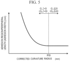
- the adhesion width at which peeling can be suppressed can be reduced, and when the corrected curvature radius R' is equal to or larger than a certain value R'0, the adhesion width at which peeling can be suppressed is constant.
- peeling can be suppressed by setting the corrected curvature radius R', the thickness t, the peripheral length L, the area A 1 , and the area A 2 such that C 2 is larger than 0, and setting the corrected curvature radius R', the thickness t, the Young's modulus E, the peripheral length L, the area A 1 , and the area A 2 such that the formula (6) is satisfied.
- Et 2 in the formula (6) is a parameter indicating the rigidity of the cover glass 12
- E(t/R') is a parameter indicating the bending stress.
- the adhesion width at which peeling can be suppressed changes in accordance with the corrected curvature radius R' and the like.
- the formula (3) can be said to be a formula that defines parameters such as the adhesion width at which peeling can be suppressed in the case where the adhesion width at which peeling can be suppressed changes. That is, in the case where C 1 is larger than 0, peeling can be suppressed by designing the curved portion 20 such that the formula (3) is satisfied.
- peeling can be suppressed by setting the corrected curvature radius R', the thickness t, the peripheral length L, the area A 1 , and the area A 2 such that C 1 is larger than 0, and setting the corrected curvature radius R', the thickness t, the Young's modulus E, the peripheral length L, the area A 1 , and the area A 2 such that the formula (3) is satisfied.
- the cover glass 12 is more firmly adhered to the frame 14, and therefore, peeling is more reliably suppressed even in the case of being affected by a high temperature, a heat cycle, mechanical vibration and impact, ultraviolet rays, or the like for a long period of time.
- the glass article 10 includes the cover glass 12 including the main surface 12A (first main surface) and the main surface 12B (second main surface), and the frame 14 adhered to the main surface 12B side of the cover glass 12 via the adhesive layer 16.
- the cover glass 12 is provided with the curved portion 20 that is convex toward the main surface 12A, and the adhesive layer 16 includes at least one of the first adhesive layer having an elastic modulus of 5 MPa in the indentation elastic modulus test and the second adhesive layer having an elastic modulus of less than 5 MPa in the indentation elastic modulus test.
- the glass article 10 includes the cover glass 12 including the main surface 12A (first main surface) and the main surface 12B (second main surface), and the frame 14 adhered to the main surface 12B side of the cover glass 12 via the adhesive layer 16.
- the cover glass 12 is provided with the curved portion 20 that is convex toward the main surface 12B, and the adhesive layer 16 includes at least one of the first adhesive layer having an elastic modulus of 5 MPa or more in the indentation elastic modulus test and the second adhesive layer having an elastic modulus of less than 5 MPa in the indentation elastic modulus test.
- the curved portion 20 When R' is represented by the formula (1) and C 1 is represented by the formula (2), the curved portion 20 satisfies the formula (3) in the case where C 1 > 0 and satisfies the formula (4) in the case where C 1 ⁇ 0. In the glass article 10 according to the present embodiment, since the curved portion 20 satisfies the formula (3) or the formula (4), peeling from the frame 14 can be suppressed. Further, the curved portion 20 preferably satisfies the formula (6) in the case where C 1 > 0.
- (A 1 +A 2 )/L is preferably 80 mm or less. In the case where (A 1 +A 2 )/L falls within this range, it is possible to suppress narrowing of the area AR0, improve designability, and suppress a screen on which an image is displayed from being reduced in size. In addition, in the case where (A 1 +A 2 )/L falls within this range, it is possible to reduce the adhesion area, facilitate the bonding, and improve the positional accuracy. In addition, (A 1 +A 2 )/L is more preferably 60 mm or less. In the case where (A 1 +A 2 )/L falls within this range, adhesion can be performed with few adhesion defects and high reliability, gas release can be promoted, and the adhesive can be appropriately spread over the entire adhesion region.
- the adhesive layer 16 may include both the first adhesive layer and the second adhesive layer, and the first adhesive layer and the second adhesive layer may be formed of different adhesives.
- the cover glass 12 and the frame 14 can be appropriately adhered.
- the cover glass 12 and the frame 14 can be adhered to each other with high positional accuracy and a sufficient adhesive force by providing adhesive layers having different characteristics, such as providing a second adhesive layer having a low adhesive force but exhibiting the adhesive force immediately after bonding, such as a double-sided tape, and a first adhesive layer having a high final adhesive strength but requiring time to exhibit the strength, such as a moisture-curable adhesive.
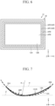
- the second adhesive layer AR2 is provided on the radially outer side of the first adhesive layer AR1 in a state where an outer peripheral edge of the first adhesive layer AR1 is separated from an inner peripheral edge of the second adhesive layerAR2.
- FIG. 6 is merely an example, and in the case where both the first adhesive layer and the second adhesive layer are provided, a position of the first adhesive layer and a position of the second adhesive layer may be freely set.
- the thickness t of the cover glass 12 is preferably 0.3 mm or more and less than 3.0 mm. By setting the thickness t within this range, peeling from the frame 14 can be suitably suppressed.
- the curvature radius R of the curved portion 20 is preferably 50 mm or more and 10,000 mm or less. By setting the curvature radius R within this range, peeling from the frame 14 can be suitably suppressed while improving the designability.
- the on-vehicle display device 2 includes the display 3 and the glass article 10 provided on a surface (front surface) of the display 3.
- the on-vehicle display device 2 can suppress peeling of the frame 14 from the cover glass 12.
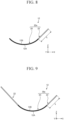
- a region in which the change in the curvature radius R at each position in a section having a length of 50 mm or less from an end point on one side toward an end point on the other side in the X direction of a region bent with the Y direction as a bending axis on the main surface 12B is larger than 5% is treated as one curved portion 20 having a spline shape.
- the curved portion 20 having a spline shape is approximated to a shape curved at a constant curvature radius, and a curvature radius approximated to the shape curved at the constant curvature radius is treated as the curvature radius R of the curved portion 20.
- one end point in the X direction of the main surface 12B of the curved portion 20 having a spline shape is defined as an end point 20J
- the other end point is defined as an end point 20K
- a plane connecting the end point 20J and the end point 20K and extending along the X direction and the Y direction is defined as a plane ⁇ .
- a curvature radius of an arc 20R passing through the end point 20J and the end point 20K and coming into contact with the plane ⁇ is defined as the curvature radius R of the curved portion 20.
- the flat portion 22 may be provided to be connected to both sides in the X direction (one direction side and the other direction side in the X direction) of the curved portion 20.
- the area of a region overlapping the first adhesive layer on the main surface 12B of the curved portion 20a (sum of the area of the region overlapping the first adhesive layer on the main surface 12B of the curved portion 20 and the area of a region overlapping the first adhesive layer on the main surface 12B of the shorter flat portion 22) is treated as the area A 1 .
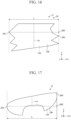
- FIG. 14 to FIG. 17 are schematic diagrams of a cover glass according to another example of the present embodiment.
- a rectangular glass plate is bent in the X direction to form the cover glass 12, and therefore, the length of the cover glass 12 in the X direction is constant at each position, but the length of the cover glass 12 in the X direction may be different for each position depending on the shape.
- the peripheral length L in such a case will be described below.
- the bending axes of the curved portions 20 are different from one another, the bending axes do not intersect with one another on the main surface 12A, whereby planar development of the cover glass 12 becomes possible, and cold forming can be appropriately performed.
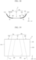
- FIG. 18 and FIG. 19 illustrate examples of schematic diagrams of the cover glass 12 in which the directions of the bending axes of the plurality of curved portions 20 are different.
- the curved portion 20A is connected to one side of the flat portion 22 in the X direction
- the curved portion 20B is connected to the other side of the flat portion 22 in the X direction.
- the flat portion 22 is connected to the other side of the curved portion 20A in the X direction, and the flat portion 22 is connected to one side of the curved portion 20B in the X direction.
- the curved portion 20A and the flat portion 22 are treated as one curved portion 20a
- the curved portion 20B and the flat portion 22 are treated as another curved portion 20a.
- a method of calculating the length F, the area A 1 , and the area A 2 of the curved portion 20a is the same as that in the case where the flat portion 22 is connected to one curved portion 20, and thus the description thereof will be omitted.
- the length F in the formula (1) for the curved portions 20A and 20B is treated as zero.
- FIG. 20 is a diagram in which the curved portion 20a including the curved portion 20A and the flat portion 22 is extracted for convenience of description.
- an end point of the side surface 12C1 on the most one side in the X direction is the position 20C of the curved portion 20a
- an end point of an end side 20P' on the most other side in the X direction is the position 20D of the curved portion 20a.
- a model corresponding to the actual test was created under the following physical properties and the conditions described in each Example, and whether peeling occurred was determined. The case where peeling did not occur was evaluated as A (bonding possible), and the case where peeling occurred in 2 msec was evaluated as B (bonding impossible).
- a glass plate made of aluminosilicate (product name: Dragontrail) manufactured by AGC Inc. was used as the glass plate.
- This glass plate was bent in a lateral direction (X direction) to be convex toward a side not adhered to a frame (first main surface side) or convex toward a side adhered to the frame (second main surface side), thereby forming a cover glass curved in the X direction, and the cover glass was adhered to a frame-shaped frame via an adhesive layer so that an end portion on a peripheral edge side did not protrude from the frame.
- a frame made of a rolled steel material SS400 was used, and as the adhesive layer, 1539 manufactured by ThreeBond Co., Ltd., which is a strong adhesive layer (first adhesive layer), or VHX-1701-04 manufactured by 3M Company, which is a weak adhesive layer (second adhesive layer), was used.
- Table 1 is a table showing properties of cover glasses according to Examples 1 and 2.
- FIG. 21 is a graph showing evaluation results of the cover glasses according to Examples 1 and 2.
- Example 1 a rectangular glass plate having a thickness t of 1.1 mm, a longitudinal (Y direction) length of 150 mm, and a lateral (X direction) length of 250 mm was prepared.
- the Young's modulus of the glass plate was 74 GPa, and a glass plate made of aluminosilicate (product name: Dangontrail) manufactured by AGC Inc. was assumed.
- the cover glass is entirely curved by being bent in the lateral direction (X direction) so as to be convex toward a side adhered to the frame (second main surface side), and therefore, a flat portion is not formed, and the entire cover glass serves as one curved portion.
- an adhesive layer an adhesive (adhesive 1539, manufactured by ThreeBond Co., Ltd.) corresponding to the first adhesive layer was assumed.
- As the frame a frame made of a rolled steel material SS400 was assumed.
- a plurality of samples having different curvature radii R, areas A 1 , and peripheral lengths L as shown in Table 1 were prepared.
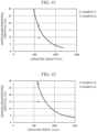
- FIG. 21 is a graph plotting a relation between the curvature radius R and a value (adhesion width) obtained by dividing the area of an adhesion region (here, area A 1 of a first adhesion region) by the peripheral length L of each of samples according to Examples 1 and 2.
- the solid line in FIG. 21 is a line serving as a boundary indicating whether the formula (3) or the formula (4) is satisfied, and it can be said that a sample of which the value of the vertical axis is equal to or larger than the solid line satisfies the formula (3) or the formula (4).
- the dotted line in FIG. 21 is a line serving as a boundary that satisfies the formula (6), and a sample of which the value of the vertical axis is equal to or larger than the dotted line satisfies the formula (6).
- Example 1 which is a Comparative Example, does not satisfy the formula (3) or the formula (4), and it is understood that the cover glass is peeled off from the frame.
- Example 2 which is an Inventive Example, satisfies the formula (3) or the formula (4), and it is understood that peeling of the cover glass from the frame can be suppressed.
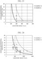
- FIG. 25 is a graph showing evaluation results of cover glasses according to Examples 9 and 10.
- Table 5 is a table showing properties of cover glasses according to Examples 13 and 14.
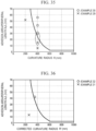
- FIG. 27 is a graph showing evaluation results of the cover glasses according to Examples 1 3 and 14.
- Example 15 which is a Comparative Example, does not satisfy the formula (3) or the formula (4), and it is understood that the cover glass is peeled off from the frame.
- Example 16 which is an Inventive Example, satisfies the formula (3) or the formula (4), and it is understood that peeling of the cover glass from the frame can be suppressed.
- Example 19 which is a Comparative Example, does not satisfy the formula (3) or the formula (4), and it is understood that the cover glass is peeled off from the frame.
- Example 20 which is an Inventive Example, satisfies the formula (3) or the formula (4), and it is understood that peeling of the cover glass from the frame can be suppressed.
- Examples 41 to 44 were the same as Examples 11 and 12 except that the Young's modulus of the glass plate was 70 GPa or 77 GPa, and the curvature radius R, the area A 2 , and the peripheral length L were shown in Table 6.
- Examples 42 and 44 which are Comparative Examples, do not satisfy the formula (3) or the formula (4), and it is understood that the cover glass is peeled off from the frame.
- Examples 41 and 43 which are Inventive Examples, satisfy the formula (3) or the formula (4), and it is understood that peeling of the cover glass from the frame can be suppressed.
- Table 7 is a table showing properties of cover glasses according to Examples 21 to 24.
- FIG. 31 is a graph showing evaluation results of the cover glasses according to Examples 21 and 22.
- Example 21 and Example 22 were the same as Example 1 and Example 2 except that the glass plate was bent in the lateral direction (X direction) to be convex toward a side not adhered to the frame (first main surface side), and the curvature radius R, the area A 2 , and the peripheral length L were as shown in Table 7.
- Example 21 which is a Comparative Example, does not satisfy the formula (6) or the formula (7), and it is understood that the cover glass is peeled off from the frame.
- Example 22 which is an Inventive Example, satisfies the formula (6) or the formula (7), and it is understood that peeling of the cover glass from the frame can be suppressed.
- Examples 23 and 24 were the same as Examples 21 and 22 except that as an adhesive layer, an adhesive (double-sided tape VHX-1701-04, manufactured by 3M Company) corresponding to the second adhesive layer was used, and the curvature radius R, the area A 2 , and the peripheral length L were as shown in Table 7.
- an adhesive double-sided tape VHX-1701-04, manufactured by 3M Company
- Example 24 which is a Comparative Example, does not satisfy the formula (6) or the formula (7), and it is understood that the cover glass is peeled off from the frame.
- Example 23 which is an Inventive Example, satisfies the formula (6) or the formula (7), and it is understood that peeling of the cover glass from the frame can be suppressed.
- Table 8 is a table showing properties of cover glasses according to Examples 25 to 28.
- FIG. 33 is a graph showing evaluation results of the cover glasses according to Examples 25 and 26.
- Examples 25 and 26 were the same as Examples 23 and 24 except that a part of the cover glass was curved to form flat portions on both sides of the curved portion, and the curvature radius R, the area A 2 , and the peripheral length L were as shown in Table 7.
- Example 25 which is a Comparative Example, does not satisfy the formula (6) or the formula (7), and it is understood that the cover glass is peeled off from the frame.
- Example 26 which is an Inventive Example, satisfies the formula (6) or the formula (7), and it is understood that peeling of the cover glass from the frame can be suppressed.
- Examples 27 and 28 were the same as Examples 21 and 22 except that a part of the cover glass was curved to form flat portions on both sides of the curved portion, and the curvature radius R, the area A 2 , and the peripheral length L were as shown in Table 7.
- Table 9 is a table showing properties of cover glasses according to Examples 29 to 36.
- FIG. 35 is a graph showing evaluation results of the cover glasses according to Examples 29 and 30.
- Examples 29 and 30 were the same as Examples 23 and 24 except that the thickness of the cover glass was 0.7 mm, and the curvature radius R, the area A 2 , and the peripheral length L were as shown in Table 9.
- Example 29 which is a Comparative Example, does not satisfy the formula (6) or the formula (7), and it is understood that the cover glass is peeled off from the frame.
- Example 30, which is an Inventive Example, satisfies the formula (6) or the formula (7), and it is understood that peeling of the cover glass from the frame can be suppressed.
- FIG. 36 is a graph showing evaluation results of the cover glasses according to Examples 31 and 32.
- Examples 31 and 32 were the same as Examples 29 and 30 except that a part of the cover glass was curved to form flat portions on both sides of the curved portion, and the curvature radius R, the area A 2 , and the peripheral length L were as shown in Table 9.
- Example 31 which is a Comparative Example, does not satisfy the formula (6) or the formula (7), and it is understood that the cover glass is peeled off from the frame.
- Example 32 which is an Inventive Example, satisfies the formula (6) or the formula (7), and it is understood that peeling of the cover glass from the frame can be suppressed.
- FIG. 37 is a graph showing evaluation results of the cover glasses according to Examples 33 and 34.
- Examples 33 and 34 were the same as Examples 21 and 22 except that the thickness of the cover glass was 0.7 mm, and the curvature radius R, the area A 2 , and the peripheral length L were as shown in Table 9.
- Example 33 which is a Comparative Example, does not satisfy the formula (6) or the formula (7), and it is understood that the cover glass is peeled off from the frame.
- Example 34 which is an Inventive Example, satisfies the formula (6) or the formula (7), and it is understood that peeling of the cover glass from the frame can be suppressed.
- FIG. 38 is a graph showing evaluation results of the cover glasses according to Examples 35 and 36.
- Examples 35 and 36 were the same as Examples 33 and 34 except that a part of the cover glass was curved to form flat portions on both sides of the curved portion, and the curvature radius R, the area A 2 , and the peripheral length L were as shown in Table 9.
- Example 35 which is a Comparative Example, does not satisfy the formula (6) or the formula (7), and it is understood that the cover glass is peeled off from the frame.
- Example 36 which is an Inventive Example, satisfies the formula (6) or the formula (7), and it is understood that peeling of the cover glass from the frame can be suppressed.
- Table 10 is a table showing properties of cover glasses according to Examples 37 to 40.
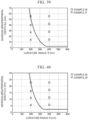
- FIG. 39 is a graph showing evaluation results of the cover glasses according to Examples 37 and 38.
- Examples 37 and 38 were the same as Examples 23 and 24 except that the thickness of the cover glass was 0.5 mm, and the curvature radius R, the area A 2 , and the peripheral length L were as shown in Table 9.
- Example 37 which is a Comparative Example, does not satisfy the formula (6) or the formula (7), and it is understood that the cover glass is peeled off from the frame.
- Example 38 which is an Inventive Example, satisfies the formula (6) or the formula (7), and it is understood that peeling of the cover glass from the frame can be suppressed.
- FIG. 40 is a graph showing evaluation results of the cover glasses according to Examples 39 and 40.
- Examples 39 and 40 were the same as Examples 21 and 22 except that the thickness of the cover glass was 0.5 mm, and the curvature radius R, the area A 2 , and the peripheral length L were as shown in Table 9.
- Example 39 which is a Comparative Example, does not satisfy the formula (6) or the formula (7), and it is understood that the cover glass is peeled off from the frame.
- Example 40 which is an Inventive Example, satisfies the formula (6) or the formula (7), and it is understood that peeling of the cover glass from the frame can be suppressed.
Landscapes
- Engineering & Computer Science (AREA)
- Chemical & Material Sciences (AREA)
- Mechanical Engineering (AREA)
- Transportation (AREA)
- Combustion & Propulsion (AREA)
- General Physics & Mathematics (AREA)
- Chemical Kinetics & Catalysis (AREA)
- Materials Engineering (AREA)
- Organic Chemistry (AREA)
- Physics & Mathematics (AREA)
- General Chemical & Material Sciences (AREA)
- Theoretical Computer Science (AREA)
- Geochemistry & Mineralogy (AREA)
- Life Sciences & Earth Sciences (AREA)
- Ceramic Engineering (AREA)
- Devices For Indicating Variable Information By Combining Individual Elements (AREA)
- Surface Treatment Of Glass (AREA)
- Joining Of Glass To Other Materials (AREA)
- Laminated Bodies (AREA)
- Instrument Panels (AREA)
Abstract
Description
- The present invention relates to a glass article and an on-vehicle display device.
- A liquid crystal display or an organic EL display may be used in an on-vehicle display device or the like that displays information or the like necessary for driving. In such a display, a cover glass may be disposed to protect a front surface. In recent years, an interior of a vehicle is required to have high designability, and a cover glass having a curved surface shape is required. As one of methods for bending a cover glass, for example, a cold forming method as disclosed in
Patent Literature 1 is known. - Patent Literature 1:
JP2017-532233A - However, the cover glass bent by, for example, a cold forming method maintains its curved shape by fixing the cover glass to a frame with an adhesive, and therefore, the cover glass may be peeled off from the frame by springback.
- The present invention has been made in view of the above problem, and an object thereof is to provide a glass article and an on-vehicle display device capable of suppressing peeling of a cover glass from a frame.
- In order to solve the above problem and implement the object, a glass article according to the present disclosure includes: a cover glass including a first main surface and a second main surface; and a frame adhered to a second main surface side of the cover glass via an adhesive layer, in which the cover glass is provided with a curved portion having a convex shape toward a direction of the second main surface, the adhesive layer includes at least one of a first adhesive layer having an elastic modulus of 5 MPa or more in an indentation elastic modulus test and a second adhesive layer having an elastic modulus of less than 5 MPa in the indentation elastic modulus test, and when R' is represented by the following formula (1) and C1 is represented by the following formula (2), the curved portion satisfies the following formula (3) in a case of C1 > 0 and satisfies the following formula (4) in a case of C1 ≤ 0.
- Here, in the following formulae, R indicates a curvature radius (mm) of the curved portion, F indicates a length of a flat region having a flat shape in a first direction orthogonal to a bending axis of the curved portion when the cover glass is provided with the flat region adjacent to the curved portion in the first direction, t indicates a thickness (mm) of the cover glass, A1 indicates an area (mm2) of the first adhesive layer in the curved portion, A2 indicates an area (mm2) of the second adhesive layer in the curved portion, E indicates a Young's modulus (GPa) of the cover glass, and L indicates a length (mm) of the curved portion in the first direction.
[Math. 1]


- In order to solve the above problem and implement the object, a glass article according to the present disclosure includes: a cover glass including a first main surface and a second main surface; and a frame adhered to a second main surface side of the cover glass via an adhesive layer, in which the cover glass is provided with a curved portion having a convex shape toward a direction of the first main surface, the adhesive layer includes at least one of a first adhesive layer having an elastic modulus of 5 MPa or more in an indentation elastic modulus test and a second adhesive layer having an elastic modulus of less than 5 MPa in the indentation elastic modulus test, and when R' is represented by the following formula (1) and C2 is represented by the following formula (5), the curved portion satisfies the following formula (6) in a case of C2 > 0 and satisfies the following formula (7) in a case of C2 ≤ 0.
- Here, in the following formulae, R indicates a curvature radius (mm) of the curved portion, F indicates a length of a flat region having a flat shape in a first direction orthogonal to a bending axis of the curved portion when the cover glass is provided with the flat region adjacent to the curved portion in the first direction, t indicates a thickness (mm) of the cover glass, A1 indicates an area (mm2) of the first adhesive layer in the curved portion, A2 indicates an area (mm2) of the second adhesive layer in the curved portion, E indicates a Young's modulus (GPa) of the cover glass, and L indicates a length (mm) of the curved portion in the first direction.
[Math. 5]


- In order to solve the above problem and implement the object, an on-vehicle display device according to the present disclosure includes a display and the glass article provided on a surface of the display.
- According to the present invention, peeling of a cover glass from a frame can be suppressed.
-
- [
FIG. 1] FIG. 1 is a schematic diagram illustrating an on-vehicle display device according to the present embodiment. - [
FIG. 2] FIG. 2 is a schematic diagram of a glass article according to the present embodiment. - [
FIG. 3] FIG. 3 is a top view of a cover glass. - [
FIG. 4] FIG. 4 is a cross-sectional view of the cover glass. - [
FIG. 5] FIG. 5 is an example of a graph for explaining a relation among characteristics of the cover glass. - [
FIG. 6] FIG. 6 is a diagram illustrating an example in which both a first adhesive layer and a second adhesive layer are provided. - [
FIG. 7] FIG. 7 is a schematic diagram of a cover glass according to another example of the present embodiment. - [
FIG. 8] FIG. 8 is a schematic diagram of a cover glass according to another example of the present embodiment. - [
FIG. 9] FIG. 9 is a schematic diagram of a cover glass according to another example of the present embodiment. - [
FIG. 10] FIG. 10 is a schematic diagram of a cover glass according to another example of the present embodiment. - [
FIG. 11] FIG. 11 is a schematic diagram of a cover glass according to another example of the present embodiment. - [
FIG. 12] FIG. 12 is a schematic diagram of a cover glass according to another example of the present embodiment. - [
FIG. 13] FIG. 13 is a schematic diagram of a cover glass according to another example of the present embodiment. - [
FIG. 14] FIG. 14 is a schematic diagram of a cover glass according to another example of the present embodiment. - [
FIG. 15] FIG. 15 is a schematic diagram of a cover glass according to another example of the present embodiment. - [
FIG. 16] FIG. 16 is a schematic diagram of a cover glass according to another example of the present embodiment. - [
FIG. 17] FIG. 17 is a schematic diagram of a cover glass according to another example of the present embodiment. - [
FIG. 18] FIG. 18 is a schematic diagram of a cover glass according to another example of the present embodiment. - [
FIG. 19] FIG. 19 is a schematic diagram of a cover glass according to another example of the present embodiment. - [
FIG. 20] FIG. 20 is a schematic diagram of a cover glass according to another example of the present embodiment. - [
FIG. 21] FIG. 21 is a graph showing evaluation results of cover glasses according to Examples 1 and 2. - [
FIG. 22] FIG. 22 is a graph showing evaluation results of cover glasses according to Examples 3 and 4. - [
FIG. 23] FIG. 23 is a graph showing evaluation results of cover glasses according to Examples 5 and 6. - [
FIG. 24] FIG. 24 is a graph showing evaluation results of cover glasses according to Examples 7 and 8. - [
FIG. 25] FIG. 25 is a graph showing evaluation results of cover glasses according to Examples 9 and 10. - [
FIG. 26] FIG. 26 is a graph showing evaluation results of cover glasses according to Examples 11 and 12. - [
FIG. 27] FIG. 27 is a graph showing evaluation results of cover glasses according to Examples 13 and 14. - [
FIG. 28] FIG. 28 is a graph showing evaluation results of cover glasses according to Examples 15 and 16. - [
FIG. 29] FIG. 29 is a graph showing evaluation results of cover glasses according to Examples 17 and 18. - [
FIG. 30] FIG. 30 is a graph showing evaluation results of cover glasses according to Examples 19 and 20. - [
FIG. 31] FIG. 31 is a graph showing evaluation results of cover glasses according to Examples 21 and 22. - [
FIG. 32] FIG. 32 is a graph showing evaluation results of cover glasses according to Examples 23 and 24. - [
FIG. 33] FIG. 33 is a graph showing evaluation results of cover glasses according to Examples 25 and 26. - [
FIG. 34] FIG. 34 is a graph showing evaluation results of cover glasses according to Examples 27 and 28. - [
FIG. 35] FIG. 35 is a graph showing evaluation results of cover glasses according to Examples 29 and 30. - [
FIG. 36] FIG. 36 is a graph showing evaluation results of cover glasses according to Examples 31 and 32. - [
FIG. 37] FIG. 37 is a graph showing evaluation results of cover glasses according to Examples 33 and 34. - [
FIG. 38] FIG. 38 is a graph showing evaluation results of cover glasses according to Examples 35 and 36. - [
FIG. 39] FIG. 39 is a graph showing evaluation results of cover glasses according to Examples 37 and 38. - [
FIG. 40] FIG. 40 is a graph showing evaluation results of cover glasses according to Examples 39 and 40. - [
FIG. 41] FIG. 41 is a graph showing evaluation results of cover glasses according to Examples 41 and 42. - [
FIG. 42] FIG. 42 is a graph showing evaluation results of cover glasses according to Examples 43 and 44. - Preferred embodiments of the present invention will be described below in detail with reference to the accompanying drawings. The present invention is not limited to these embodiments and in the case where there are a plurality of embodiments, also includes a combination of the embodiments. In addition, rounding ranges are included for numerical values.
-
FIG. 1 is a schematic diagram illustrating an on-vehicle display device according to the present embodiment. As illustrated inFIG. 1 , aglass article 10 according to the present embodiment is provided in an on-vehicle display device 2, and is used as a cover member for a surface (front surface) of adisplay 3 on which an image is displayed. - The on-
vehicle display device 2 is a display device provided in a vehicle, and is provided on a front side of asteering shaft 1 in the vehicle, for example. Thedisplay 3 displays a car navigation screen, various meters such as a speed meter, a start button, and the like. However, the configuration ofFIG. 1 is an example, and the on-vehicle display device 2 to which theglass article 10 is applied may have any configuration. In addition, theglass article 10 is not limited to being used as a cover member for a surface of the on-vehicle display device 2, and may be used for any application. -
FIG. 2 is a schematic diagram of the glass article according to the present embodiment. As illustrated inFIG. 2 , theglass article 10 includes acover glass 12, aframe 14, and anadhesive layer 16. Thecover glass 12 is a transparent plate-shaped glass member and includes amain surface 12A (first main surface) which is a main surface on one side and amain surface 12B (second main surface) which is a main surface on a side opposite to themain surface 12A. When theglass article 10 is mounted on an object to be mounted such as the on-vehicle display device 2, themain surface 12A of thecover glass 12 becomes a side exposed to the outside, and themain surface 12B becomes a side facing the object to be mounted (here, the display 3). The term "transparent" as used herein indicates allowing visible light to be transmitted. - The
frame 14 is a frame-like member attached to themain surface 12B of thecover glass 12. Theframe 14 is made of, for example, a resin or a metal, but is not limited thereto, and may be formed of any material. Since thecover glass 12 is curved in an X direction (first direction) as described later, theframe 14 is also curved in the X direction along thecover glass 12. Theframe 14 is attached to a peripheral edge portion of themain surface 12B of thecover glass 12. - In the example of
FIG. 2 , theframe 14 is provided over an entire section of the peripheral edge portion of themain surface 12B of thecover glass 12 in a peripheral direction. However, theframe 14 is not limited thereto, and may be provided discontinuously at a part of the section. In addition, in the example ofFIG. 2 , an end portion of thecover glass 12 on a peripheral edge side does not protrude from theframe 14, but without being limited thereto, the end portion of thecover glass 12 on the peripheral edge side may protrude from theframe 14. - In the example of
FIG. 2 , theframe 14 is provided on a peripheral edge of thecover glass 12 and has a frame shape in which an inner side thereof is opened, but theframe 14 may have a box shape with no opening. That is, a plate-shaped member that covers the opening may be provided on a Z-direction side of theframe 14 inFIG. 2 . In this manner, the shape of theframe 14 and the attachment position on themain surface 12B are not limited to the above description, and may be any shape and any position. - The
frame 14 is fixed (adhered) to themain surface 12B of thecover glass 12 via theadhesive layer 16. That is, theadhesive layer 16 is provided between theframe 14 and themain surface 12B of thecover glass 12, and adheres a surface of theframe 14 on acover glass 12 side and themain surface 12B of thecover glass 12. Theadhesive layer 16 may be formed of any adhesive member capable of adhering theframe 14 and thecover glass 12, such as a double-sided tape or an adhesive. - The
glass article 10 includes at least one of a first adhesive layer and a second adhesive layer as theadhesive layer 16. The first adhesive layer indicates an adhesive layer having an elastic modulus of 5 MPa or more in an indentation elastic modulus test, and the second adhesive layer indicates an adhesive layer having an elastic modulus of less than 5 MPa in the indentation elastic modulus test. That is, an indentation elastic modulus of the first adhesive layer is higher than the indentation elastic modulus of the second adhesive layer. The elastic modulus of the first adhesive layer in the indentation elastic modulus test is preferably less than 100 MPa, and more preferably less than 30 MPa. Here, the elastic modulus of the first contact layer in the indentation elastic modulus test is preferably 5 MPa or more and less than 100 MPa, and more preferably 5 MPa or more and less than 30 MPa. The elastic modulus of the second adhesive layer in the indentation elastic modulus test is preferably 0.2 MPa or more, and more preferably 0.5 MPa or more. Here, the elastic modulus of the second contact layer in the indentation elastic modulus test is preferably 0.2 MPa or more and less than 5 MPa, and more preferably 0.5 MPa or more and less than 5 MPa. - The first adhesive layer and the second adhesive layer are composed of different adhesive members. It can be said that the adhesive member constituting the first adhesive layer has a higher adhesive strength than the adhesive member constituting the second adhesive layer. The
adhesive layer 16 may include three or more types of adhesive members. - The indentation elastic modulus test in the present embodiment is performed by the following method.
- The
adhesive layer 16 adhered to themain surface 12B of thecover glass 12 and theframe 14 is exposed toward an upper side in a vertical direction and is disposed on a creep meter (for example, model number RE2-33005C, manufactured by Yamaden Co., Ltd.), and a plunger (for example, a cylindrical plunger, model number P-61, ϕ1.5, H40, manufactured by Yamaden Co., Ltd.) is indented on theadhesive layer 16 at an indentation speed of 0.05 mm/sec in an environment of room temperature, for example, 20°C, and a relative humidity of 50%, until an indentation depth becomes 5% to 10% of the thickness of theadhesive layer 16. - A method of exposing the adhesive layer is not particularly limited, but a method in which the adhesive is not denatured is preferable. Examples thereof include a method of inserting a metal thin plate or the like between the first adhesive layer and the
cover glass 12 or theframe 14, which is an object to be adhered, and physically peeling off the above members. In the case where the adhesive layer is broken in the middle of a thickness direction during peeling, it is preferable to measure the elastic modulus of the adhesive layer which remains thicker. - It addition, it is also preferable to measure the elastic modulus using the adhesive layer remaining on a member with a higher Young's modulus in the
frame 14 and thecover glass 12. That is, it is preferable to measure the elastic modulus by causing the adhesive layer to remain on a frame side in the case where the frame is made of a metal, and causing the adhesive layer to remain on a cover glass side in the case where the frame is made of a resin having a low Young's modulus. - Next, a load acting on the plunger when the plunger is indented and a displacement amount in the indentation direction of the plunger are sequentially measured, the load and the displacement amount are plotted for each time, and a slope of an approximate line of each plotted point is calculated as the elastic modulus of the
adhesive layer 16. This indentation elastic modulus test is performed for each position of theadhesive layer 16, and a region where the elastic modulus is 5 MPa or more is defined as the first adhesive layer, and a region where the elastic modulus is less than 5 MPa is defined as the second adhesive layer. It is preferable to perform the indentation elastic modulus test twice at the same position by plotting every 0.04 seconds. A position where the elastic modulus is 5 MPa or more in both of two measurements may be defined as the first adhesive layer, and a position where the elastic modulus is less than 5 MPa in both of the two measurements may be defined as the second adhesive layer. - Here, a meaning of the indentation elastic modulus test in the present invention will be described. In the glass article, the adhesive adheres a glass surface or a printing surface on the glass surface with the frame made of a metal or a resin. A material of the adhesive is generally designed so that the glass surface and the object to be adhered are peeled by the adhesive being broken when the adhered glass surface and the object to be adhered are to be peeled. Further, it is known that the adhesive strength when the adhesive is broken depends on a tensile elastic modulus of the adhesive. However, it is difficult to perform measurement in a glass article in a state where a cover glass and a frame are adhered to each other, by a cross-shaped adhesive strength test, an H-type adhesive strength test, or the like, which is known as an existing adhesive strength test. In the present invention, an indentation elastic modulus test capable of being verified from a glass article in a state where a cover glass and a frame are adhered to each other is adopted as an evaluation method in place of the existing adhesive strength test. In the present invention, since the adhesive is broken when the frame is peeled off from the glass article, and it is known that there is generally a positive correlation between the tensile elastic modulus and the indentation elastic modulus, it is presumed that there is also a correlation between the adhesive strength and the elastic modulus in the indentation test.
- The
cover glass 12 is attached to theframe 14 while being curved. In the present embodiment, thecover glass 12 is attached to theframe 14 by bending a flat plate-shaped glass plate by a cold forming method. That is, thecover glass 12 is attached to theframe 14 in a state where bending stress is applied. Hereinafter, thecover glass 12 will be described more specifically. The term "cold forming" as used herein indicates a method of bending the glass into a desired shape without increasing the temperature thereof to a softening point. -
FIG. 3 is a top view of the cover glass, andFIG. 4 is a cross-sectional view of the cover glass. In the example ofFIG. 3 , thecover glass 12 has a shape in which a rectangular flat plate-shaped glass plate is curved. Hereinafter, one side surface (end surface) of thecover glass 12 is defined as a side surface 12C1, a side surface facing the side surface 12C1 is defined as a side surface 12C2, another side surface of thecover glass 12 is defined as a side surface 12C3, and a side surface facing the side surface 12C3 is defined as a side surface 12C4. - In the example of
FIG. 3 , the side surfaces 12C1 and 12C2 are short sides of the rectangle, and the side surfaces 12C3 and 12C4 are long sides of the rectangle. Thecover glass 12 is not limited to a shape in which a rectangular flat plate-shaped glass plate is curved, and may be a shape in which a glass plate having any shape is curved. For example, thecover glass 12 may have a shape in which a polygonal, circular, or elliptical flat plate-shaped glass plate is curved. -
FIG. 3 is a view when thecover glass 12 is viewed from a normal direction (Z direction) of a position P on themain surface 12B of thecover glass 12, andFIG. 4 illustrates a cross section S of thecover glass 12 along the X direction. - Here, a tangential direction selected so as to satisfy the following conditions among tangential directions of the
main surface 12B at an arbitrary point P of themain surface 12B of thecover glass 12 is defined as an X direction (first direction), a direction orthogonal to the X direction among the tangential directions of themain surface 12B at the point P is defined as a Y direction, and a direction orthogonal to the X direction and the Y direction, that is, a normal direction (thickness direction) of the position P is defined as a Z direction. Here, the X direction indicates a direction in which, among the tangential directions of themain surface 12B at the arbitrary point P of themain surface 12B of thecover glass 12, a curvature radius of a line formed by intersection of themain surface 12B and a plane including the tangential direction and the normal direction becomes minimum. - Since the
cover glass 12 according to the present embodiment is uniaxially bent, the X direction can be unambiguously defined even when the position P is set to any point. However, as in another example described later, a plurality ofcurved portions 20 may be provided, and bending directions of the respectivecurved portions 20 may intersect with one another. In this case, the X direction may be defined for eachcurved portion 20. That is, among tangential directions of the position P on onecurved portion 20, a direction in which a curvature radius of a line formed by intersection of themain surface 12B and a plane including a tangential direction and a normal direction is minimum may be defined as the X direction of thiscurved portion 20, and the X direction may be defined in the same manner for eachcurved portion 20. - In the case where there are a plurality of tangential directions in which a curvature radius of a line formed by intersection of the
main surface 12B and a plane including a tangential direction and a normal direction is minimum, at least one direction of the tangential directions may be defined as the X direction. Hereinafter, a curvature radius of a line formed by intersection of themain surface 12B and a plane including the X direction and the Z direction is referred to as a curvature radius R1. - It can be said that the
cover glass 12 is curved with a curvature radius R with the Y direction as a bending axis and the X direction as a direction orthogonal to the bending axis. The curvature radius R of the cover glass 12 (curvature radius of bending with the Y direction as the bending axis) is preferably 50 mm or more and 10,000 mm or less, more preferably 100 mm or more and 5,000 mm or less, and still more preferably 200 mm or more and 3,000 mm or less. In the case where the curvature radius R falls within this range, peeling from the frame can be suppressed while improving designability. Further, the curvature radius may be, for example, 2,000 mm or less, 1,750 mm or less, 1,500 mm or less, 1,250 mm or less, and 1,000 mm or less. In the case where the curvature radius is within this range, peeling from the frame is likely to occur in the related art, but peeling can be significantly suppressed by satisfying the formula of the present invention. - The
cover glass 12 is preferably not bent in a direction other than a bending direction with the Y direction as a bending axis. Thecover glass 12 preferably does not have bending with the X direction as a bending axis, in other words, a trajectory on themain surface 12B of thecover glass 12 along the Y direction is preferably linear. The term "not have bending" is not limited to the case where the curvature radius is infinite, and may include the case where the curvature radius is larger than 10,000 mm. In the case where thecover glass 12 is not bent in a direction other than a direction with the Y direction as a bending axis in this manner, thecover glass 12 can be developed in a plane and cold forming can be appropriately performed. - Hereinafter, a portion of the
cover glass 12 that is bent with the Y direction as a bending axis is referred to as thecurved portion 20. Thecurved portion 20 indicates a region of thecover glass 12 that is bent with the same curvature radius R with the Y direction as a bending axis. That is, it can be said that thecurved portion 20 of thecover glass 12 is bent with the curvature radius R with the Y direction as a bending axis. In the example ofFIG. 4 , since theentire cover glass 12 is bent with the same curvature radius R in the X direction, it can be said that theentire cover glass 12 is thecurved portion 20. - The expression "the curvature radius R is the same" as used herein is not limited to the case where the curvature radius R is strictly the same for each position. For example, in the case where the change in the measured curvature radius R is 5% or less at each position from an end point on one side to an end point on the other side in the X direction of a region bent with the Y direction as a bending axis on the
main surface 12B of thecover glass 12, that is, in the case where a difference between a maximum value and a minimum value of the curvature radius R at each position is 5% or less of the maximum value of the curvature radius R at each position, the region is regarded as a region having the same curvature radius and is treated as onecurved portion 20. An average value of the curvature radius R at each position of thecurved portion 20 may be treated as the curvature radius R of thecurved portion 20. - Examples of a method of measuring the curvature radius R of the
cover glass 12 include a method of measuring a shape by using a contact type or non-contact type three-dimensional measuring machine and obtaining the curvature radius R based on shape data, and a method of pressing an R ruler against thecover glass 12 and measuring the curvature radius R. - In the present embodiment, the
curved portion 20 is bent to be convex toward amain surface 12A side. However, thecurved portion 20 is not limited to being bent to be convex toward themain surface 12A side, and may be bent to be convex toward amain surface 12B side. - The arbitrary point P described above is any point in the
curved portion 20 of themain surface 12B, and for example, may be a central position of themain surface 12B (for example, a position of a center of gravity of the cover glass 12) in the case where a central region of themain surface 12A is thecurved portion 20. That is, the X direction and the Y direction may be tangential directions from the center of themain surface 12B, and the Z direction may be a normal direction at the center of themain surface 12B. - The length of the
curved portion 20 in the X direction orthogonal to the bending axis is defined as a peripheral length L. The peripheral length L indicates the length of a line extending in the X direction on themain surface 12B and connecting an end point (position) on one side of thecurved portion 20 in the X direction to an end point (position) on the other side of thecurved portion 20 in the X direction. - The line extending in the X direction on the
main surface 12B indicates a line extending in the X direction along themain surface 12B without shifting in the Y direction. In the example ofFIG. 3 , the end point on one side of thecurved portion 20 in the X direction is a point on the side surface 12C1, the end point on the other side of thecurved portion 20 in the X direction is a point on the side surface 12C2, and therefore, the peripheral length L indicates the length of a line extending in the X direction on themain surface 12B from the side surface 12C1 to the side surface 12C2. - The peripheral length L is preferably 100 mm or more and 2,000 mm or less, more preferably 150 mm or more and 700 mm or less, and still more preferably 200 mm or more and 400 mm or less. Here, the peripheral length L is preferably 100 mm or more, more preferably 150 mm, and still more preferably 200 mm or more, and is preferably 2,000 mm or less, more preferably 700 mm or less, and still more preferably 400 mm or less. In the case where the peripheral length L falls within this range, peeling from the frame can be suppressed while improving designability.
- In the present embodiment, even in a region where the curvature radius R is the same, a region in which the peripheral length L is 5 mm or less (for example, surface unevenness or fine undulation) is not treated as the
curved portion 20. That is, a region where the curvature radius R is the same and the peripheral length L is longer than 5 mm is defined as thecurved portion 20. - The length of the
curved portion 20 in the Y direction as the bending axis is preferably 80 mm or more and 500 mm or less, more preferably 100 mm or more and 400 mm or less, and still more preferably 120 mm or more and 300 mm or less. Here, the length in the Y direction is preferably 80 mm or more, more preferably 100 mm or more, and still more preferably 120 mm or more, and is preferably 500 mm or less, more preferably 400 mm or less, and still more preferably 300 mm or less. - The length of the
curved portion 20 in the Y direction indicates the length of a line extending in the Y direction on themain surface 12B and connecting an end point (position) on one side of thecurved portion 20 in the Y direction to an end point (position) on the other side of thecurved portion 20 in the Y direction. - The line extending in the Y direction on the
main surface 12B indicates a line extending in the Y direction along themain surface 12B without shifting in the X direction. In the example ofFIG. 3 , the respective points are points on the side surfaces 12C3 and 12C4, and therefore, the length of thecurved portion 20 in the Y direction indicates the length of a line extending in the Y direction on themain surface 12B from the side surface 12C3 to the side surface 12C4. - The thickness t of the
cover glass 12 is preferably 0.3 mm or more and 3.0 mm or less, more preferably 0.4 mm or more and 1.5 mm or less, and still more preferably 0.6 mm or more and 1.3 mm or less. Here, the thickness t is preferably 0.3 mm or more, more preferably 0.4 mm or more, and still more preferably 0.6 mm or more, and is preferably 3.0 mm or less, more preferably 1.5 mm or less, and still more preferably 1.3 mm or less. In the case where the thickness t falls within this range, peeling from the frame can be suppressed while improving designability. The thickness t indicates the distance from themain surface 12A to themain surface 12B in the Z direction. - The Young's modulus E of the
cover glass 12 is preferably 60 GPa or more and 90 GPa or less, more preferably 68 GPa or more and 78 GPa or less, and still more preferably 72 GPa or more and 76 GPa or less. Here, the Young's modulus E is preferably 60 GPa or more, more preferably 68 GPa or more, and still more preferably 72 GPa, and is preferably 90 GPa or less, more preferably 78 GPa or less, and still more preferably 76 GPa or less. In the case where the Young's modulus E falls within this range, peeling from the frame can be suppressed while improving designability. - A glass material for the
cover glass 12 is any material, and for example, an alkali-free glass, a soda lime glass, a soda lime silicate glass, an aluminosilicate glass, a borosilicate glass, a lithium aluminosilicate glass, and a borosilicate glass can be used. Thecover glass 12 is preferably an aluminosilicate glass or a lithium aluminosilicate glass to which a large stress is easily introduced by a tempering treatment even in the case where the thickness is thin and by which a glass with a high strength can be obtained even in the case where the thickness is thin. A chemical tempering treatment is generally performed by immersing a glass in a molten salt containing alkali metals. - The
cover glass 12 preferably contains, in terms of mol% based on oxides, 50% to 80% of SiO2, 0.1 % to 25% of Al2O3, 3% to 30% of Li2O+Na2O+K2O, 0% to 25% of MgO, 0% to 25% of CaO, and 0% to 5% of ZrO2, but is not particularly limited thereto. Here, "50% to 80%" as used herein indicates 50% or more and 80% or less when mol% of the total amount of thecover glass 12 is defined as 100%, and other numerical ranges are defined in the same manner. In addition, "Li2O+Na2O+K2O" indicates the total content of Li2O, Na2O, and K2O. In the case where thecover glass 12 has the following composition, the rigidity can also be appropriately maintained even when thecover glass 12 is curved. - More specifically, a more preferable composition of the glass for the
cover glass 12 includes the following glass compositions. For example, "containing 0% to 25% of MgO" means that MgO is not essential but may be contained up to 25%. - Glass of (i) is categorized in the soda lime silicate glass, glass of (ii) and (iii) are categorized in the aluminosilicate glass, and glass of (iv) and (v) are categorized in the lithium aluminosilicate glass.
- (i) Glass having a composition containing, in terms of mol%, 63% to 73% of SiO2, 0.1% to 5.2% of Al2O3, 10% to 16% of Na2O, 0% to 1.5% of K2O, 0% to 5.0% of Li2O, 5% to 18% of MgO, and 1% to 10% of CaO
- (ii) Glass having a composition containing, in terms of mol%, 50% to 74% of SiO2, 5% to 15% of Al2O3, 10% to 20% of Na2O, 0% to 8% of K2O, 0% to 5.0% of Li2O, 2% to 15% of MgO, 0% to 6% of CaO, and 0% to 5% of ZrO2, in which the total content of SiO2 and Al2O3 is 65% to 85%, the total content of Na2O and K2O is 12% to 25%, and the total content of MgO and CaO is 1% to 15%
- (iii) Glass having a composition containing, in terms of mol%, 68% to 80% of SiO2, 4% to 10% of Al2O3, 5% to 15% of Na2O, 0% to 1% of K2O, 0% to 5.0% of Li2O, 4% to 15% of MgO, and 0% to 1% of ZrO2
- (iv) Glass having a composition containing, in terms of mol%, 67% to 75% of SiO2, 0% to 4% of Al2O3, 7% to 15% of Na2O, 1% to 9% of K2O, 0% to 5.0% of Li2O, 6% to 14% of MgO, and 0% to 1.5% of ZrO2, in which the total content of SiO2 and Al2O3 is 71% to 75%, the total content of Na2O and K2O is 12% to 20%, and the content of CaO is less than 1% in the case where CaO is contained
- (v) Glass having a composition containing, in terms of mol%, 50% to 73% of SiO2, 5% to 20% of Al2O3, 0% to 6% of B2O3, 0% to 10% of P2O5, 4% to 12% of Li2O, 3% to 20% of Na2O, 0% to 5% of K2O, 0% to 8% of MgO, 0% to 2% of CaO, 0% to 5% of SrO, 0% to 5% of BaO, 0% to 5% of ZnO, 0% to 2% of TiO2, and 0% to 4% of ZrO2
- In the entire
main surface 12B of thecurved portion 20, a region overlapping theadhesive layer 16 is defined as an adhesion region AR, and a region not overlapping theadhesive layer 16 is defined as a region AR0. The adhesion region AR is formed on a radially outer side of the region ARC when an axis passing through a central position of thecurved portion 20 along the Z direction is defined as an axial direction. - In the present embodiment, the
entire cover glass 12 constitutes thecurved portion 20, and therefore, a region overlapping theadhesive layer 16 in the entiremain surface 12B of thecover glass 12 is the adhesion region AR. The adhesion region AR may not be continuous, and a plurality of discontinuous or mottled adhesion regions AR may be formed. - In addition, a region overlapping the first adhesive layer having an elastic modulus of 5 MPa or more (region overlapping the first adhesive layer in the adhesion region AR) in the entire
main surface 12B of thecurved portion 20 is defined as a first adhesion region, and a region overlapping the second adhesive layer having an elastic modulus of less than 5 MPa (region overlapping the second adhesive layer in the adhesion region AR) in the entiremain surface 12B of thecurved portion 20 is defined as a second adhesion region. - In the present embodiment, the
entire cover glass 12 constitutes thecurved portion 20, and therefore, a region overlapping the first adhesive layer in the entiremain surface 12B of thecover glass 12 is the first adhesion region, and a region overlapping the second adhesive layer in the entiremain surface 12B of thecover glass 12 is the second adhesion region. - In this case, the area A1 of the first adhesion region is preferably 8,288 mm2 or less, and the area A2 of the second adhesion region is preferably 20,214 mm2 or less. In addition, a value ((A1+A2)/L) obtained by dividing, by the peripheral length L, a value obtained by summing the area A1 of the first adhesion region and the area A2 of the second adhesion region (region AR in the present embodiment) is preferably 80 mm or less. The area A1 of the first adhesion region may be referred to as an area of the first adhesive layer in the curved portion, and the area A2 of the second adhesion region may be referred to as an area of the second adhesive layer in the curved portion.
- This preferable numerical range can be applied to all of the case where the second adhesion region is not provided and the first adhesion region is provided, the case where the first adhesion region is not provided and the second adhesion region is provided, and the case where both the first adhesion region and the second adhesion region are provided.
- In the case where the second adhesion region is not provided and the first adhesion region is provided, the area A1 of the first adhesion region is preferably 350 mm2 or more and 95,000 mm2 or less, more preferably 740 mm2 or more and 25,000 mm2 or less, and still more preferably 1,500 mm2 or more and 8,500 mm2 or less. Here, the area A1 of the first adhesion region is preferably 350 mm2 or more, more preferably 740 mm2 or more, and still more preferably 1,500 mm2 or more, and is preferably 95,000 mm2 or less, more preferably 25,000 mm2 or less, and still more preferably 8,500 mm2 or less.
- In this case, a value (A1/L) obtained by dividing the area A1 of the first adhesion region by the peripheral length L is preferably 50 mm or less, more preferably 35 mm or less, and still more preferably 25 mm or less.
- In addition, in the case where the first adhesion region is not provided and the second adhesion region is provided, the area A2 of the second adhesion region is preferably 850 mm2 or more and 230,000 mm2 or less, more preferably 1,700 mm2 or more and 60,000 mm2 or less, and still more preferably 3,800 mm2 or more and 20,000 mm2 or less. Here, the area A2 of the second adhesion region is preferably 850 mm2 or more, more preferably 1,700 mm2 or more, and still more preferably 3,800 mm2 or more, and is preferably 230,000 mm2 or less, more preferably 60,000 mm2 or less, and still more preferably 20,000 mm2 or less.
- In addition, in this case, a value (A2/L) obtained by dividing the area A2 of the second adhesion region by the peripheral length L is preferably 115 mm or less, more preferably 85 mm or less, and still more preferably 50 mm or less.
- In addition, in the case where both the first adhesion region and the second adhesion region are provided, the area A1 of the first adhesion region is preferably 170 mm2 or more and 47,000 mm2 or less, more preferably 370 mm2 or more and 12,000 mm2 or less, and still more preferably 790 mm2 or more and 4,200 mm2 or less. In addition, the area A2 of the second adhesion region is preferably 420 mm2 or more and 1 10,000 mm2 or less, more preferably 880 mm2 or more and 29,000 mm2 or less, and still more preferably 1,900 mm2 or more and 10,000 mm2 or less. Here, the area A1 of the first adhesion region is preferably 170 mm2 or more, more preferably 370 mm2 or more, and still more preferably 790 mm2 or more, and is preferably 47,000 mm2 or less, more preferably 12,000 mm2 or less, and still more preferably 4,200 mm2 or less. In addition, the area A2 of the second adhesion region is preferably 420 mm2 or more, more preferably 880 mm2 or more, and still more preferably 1,900 mm2 or more, and is preferably 110,000 mm2 or less, more preferably 29,000 mm2 or less, and still more preferably 10,000 mm2 or less.
- In addition, in this case, the value ((A1+A2)/L) obtained by dividing, by the peripheral length L, the value obtained by summing the area A1 of the first adhesion region and the area A2 of the second adhesion region (region AR in the present embodiment) is preferably 80 mm or less, more preferably 60 mm or less, and still more preferably 40 mm or less.
- In the case where the areas of the first adhesion region and the second adhesion region fall within these ranges, peeling from the frame can be suppressed while suppressing the region AR0 in which the image is displayed from becoming small. For example, a printed layer is formed in the adhesion region AR, and the region ARC is used as, for example, a displaying portion.
- Here, in the case where the cover glass is curved and adhered to the frame, the cover glass may be peeled off from the frame by springback, that is, by a force of the cover glass returning to a flat plate shape. As a result of diligent studies, the present inventors have devised that peeling from the frame can be suppressed by setting a relation among the characteristics of the cover glass 12 (in the present embodiment, a relation among the curvature radius R, the thickness t, the Young's modulus E, the peripheral length L, and the areas of the first adhesion region and the second adhesion region) to an appropriate range. Hereinafter, the relation among the characteristics of the
cover glass 12 will be described. - Hereinafter, a correction value of the curvature radius R of the
curved portion 20 is referred to as a corrected curvature radius R'. The corrected curvature radius R' is represented by the following formula (1). The corrected curvature radius R' is a correction value of the curvature radius R in the case where flat regions (flat portions) that are not bent and are flat are connected to both sides (one direction side and the other direction side in the X direction) of thecurved portion 20 in the X direction.
[Math. 9]
- The length F in the formula (1) is the length in the X direction of the flat portion having a shorter length in the X direction among the flat portions adjacently connected to both sides of the
curved portion 20 in the X direction. That is, the length F is the length of the flat portion having a shorter length in the X direction, along a main surface of the flat portion, from an end portion on one side in the X direction (end portion on a side connected to the curved portion 20) to an end portion on the other side in the X direction of the flat portion (end portion on a side not connected to the curved portion 20). In the present embodiment, the flat portion is not provided, and therefore, F is zero, and the corrected curvature radius R' is the same value as the curvature radius R. An example in which a flat portion is provided will be described later. - The case where the
curved portion 20 is curved to be convex toward themain surface 12A side will be described. In the case where thecurved portion 20 is curved to be convex toward themain surface 12A side, when C2 is defined to a value represented by the following formula (5), thecurved portion 20 satisfies the following formula (6) in the case where C2 is larger than 0 (C2 > 0), and thecurved portion 20 satisfies the following formula (7) in the case where C2 is equal to or smaller than 0 (C2 ≤ 0). In the formulae (5) to (7), A2 is zero in the case where the second adhesion region is not provided, and A1 is zero in the case where the first adhesion region is not provided.
[Math. 10]


- The formulae (5) to (7) will be described.
FIG. 5 is an example of a graph explaining the relation among the characteristics of the cover glass. InFIG. 5 , the horizontal axis represents the corrected curvature radius R', and the vertical axis represents a value obtained by dividing the area (A1+A2) of the adhesion region AR by the peripheral length L, which is appropriately referred to as an adhesion width hereinafter. - The curve in
FIG. 5 shows a value of the adhesion width serving as a boundary at which the frame is peeled off for each corrected curvature radius R' when the thickness t and the Young's modulus E are set to predetermined values. That is, it can be said that when the thickness t and the Young's modulus E are predetermined values, peeling of the frame can be suppressed by setting the value of the adhesion width higher than the curve inFIG. 5 . As shown by the curve inFIG. 5 , as the corrected curvature radius R' increases, the adhesion width at which peeling can be suppressed can be reduced, and when the corrected curvature radius R' is equal to or larger than a certain value R'0, the adhesion width at which peeling can be suppressed is constant. - As shown in the graph of
FIG. 5 , when C2 is equal to or smaller than 0, the adhesion width at which peeling can be suppressed is constant. That is, C2 in the formula (5) is an index value for determining whether the adhesion width at which peeling can be suppressed is constant, and the formula (7) can be said to be a formula that defines the adhesion width at which peeling can be suppressed in the case where the adhesion width at which peeling can be suppressed is constant. That is, in the case in the case where C2 is equal to or smaller than 0, peeling can be suppressed by designing thecurved portion 20 such that the formula (7) is satisfied. In other words, peeling can be suppressed by setting the corrected curvature radius R', the thickness t, the peripheral length L, the area A1, and the area A2 such that C2 is equal to or smaller than 0, and setting the peripheral length L, the area A1, and the area A2 such that the formula (7) is satisfied. - On the other hand, as shown in the graph of
FIG. 5 , in the case where C2 is larger than 0, the adhesion width at which peeling can be suppressed changes in accordance with the corrected curvature radius R' and the like. The formula (6) can be said to be a formula that defines parameters such as the adhesion width at which peeling can be suppressed in the case where the adhesion width at which peeling can be suppressed changes. That is, in the case where C2 is larger than 0, peeling can be suppressed by designing thecurved portion 20 such that the formula (6) is satisfied. In other words, peeling can be suppressed by setting the corrected curvature radius R', the thickness t, the peripheral length L, the area A1, and the area A2 such that C2 is larger than 0, and setting the corrected curvature radius R', the thickness t, the Young's modulus E, the peripheral length L, the area A1, and the area A2 such that the formula (6) is satisfied. Et2 in the formula (6) is a parameter indicating the rigidity of thecover glass 12, and E(t/R') is a parameter indicating the bending stress. - The case where the
curved portion 20 is curved to be convex toward themain surface 12B side will be described. In the case where thecurved portion 20 is curved to be convex toward themain surface 12B side, when C1 is set to a value represented by the following formula (2), thecurved portion 20 satisfies the following formula (3) in the case where C1 is larger than 0 (C1 > 0), and thecurved portion 20 satisfies the following formula (4) in the case where C1 is equal to or smaller than 0 (C1 ≤ 0). In the formulae (2) to (4), A2 is zero in the case where the second adhesion region is not provided, and A1 is zero in the case where the first adhesion region is not provided.
[Math. 13]


- As shown in the graph of
FIG. 5 , in the case where C1 is equal to or smaller than 0, the adhesion width at which peeling can be suppressed is constant. C1 in the formula (2) is an index value for determining whether the adhesion width at which peeling can be suppressed is constant, and the formula (4) can be said to be a formula that defines the adhesion width at which peeling can be suppressed in the case where the adhesion width at which peeling can be suppressed is constant. That is, in the case where C1 is equal to or smaller than 0, peeling can be suppressed by designing thecurved portion 20 such that the formula (4) is satisfied. In other words, peeling can be suppressed by setting the corrected curvature radius R', the thickness t, the peripheral length L, the area A1, and the area A2 such that C1 is equal to or smaller than 0, and setting the peripheral length L, the area A1, and the area A2 such that the formula (4) is satisfied. - On the other hand, as shown in the graph of
FIG. 5 , in the case where C1 is larger than 0, the adhesion width at which peeling can be suppressed changes in accordance with the corrected curvature radius R' and the like. The formula (3) can be said to be a formula that defines parameters such as the adhesion width at which peeling can be suppressed in the case where the adhesion width at which peeling can be suppressed changes. That is, in the case where C1 is larger than 0, peeling can be suppressed by designing thecurved portion 20 such that the formula (3) is satisfied. In other words, peeling can be suppressed by setting the corrected curvature radius R', the thickness t, the peripheral length L, the area A1, and the area A2 such that C1 is larger than 0, and setting the corrected curvature radius R', the thickness t, the Young's modulus E, the peripheral length L, the area A1, and the area A2 such that the formula (3) is satisfied. - In the case where C1 is larger than 0 (C1 > 0), the
curved portion 20 preferably further satisfies the following formula (6). Also in the formula (6), A2 is zero in the case where the second adhesion region is not provided, and A1 is zero in the case where the first adhesion region is not provided. - In the case where the
curved portion 20 satisfies the formula (6), thecover glass 12 is more firmly adhered to theframe 14, and therefore, peeling is more reliably suppressed even in the case of being affected by a high temperature, a heat cycle, mechanical vibration and impact, ultraviolet rays, or the like for a long period of time. - In addition, when the
curved portion 20 satisfies the formula (6), in the case where a curved portion convex toward themain surface 12A side is further provided in addition to a curved portion convex toward themain surface 12B side as inFIG. 13 , the peeling can be suppressed even when the adhesion width with the frame is the same in both the curved portions, and therefore, there is an advantage that the design is excellent.
[Math. 16]
- As described above, the
glass article 10 according to the present embodiment includes thecover glass 12 including themain surface 12A (first main surface) and themain surface 12B (second main surface), and theframe 14 adhered to themain surface 12B side of thecover glass 12 via theadhesive layer 16. Thecover glass 12 is provided with thecurved portion 20 that is convex toward themain surface 12A, and theadhesive layer 16 includes at least one of the first adhesive layer having an elastic modulus of 5 MPa in the indentation elastic modulus test and the second adhesive layer having an elastic modulus of less than 5 MPa in the indentation elastic modulus test. When R' is represented by the formula (1) and C2 is represented by the formula (5), thecurved portion 20 satisfies the formula (6) in the case where C2 > 0 and satisfies the formula (7) in the case where C2 ≤ 0. In theglass article 10 according to the present embodiment, since thecurved portion 20 satisfies the formula (6) or the formula (7), peeling from theframe 14 can be suppressed. - As described above, the
glass article 10 according to the present embodiment includes thecover glass 12 including themain surface 12A (first main surface) and themain surface 12B (second main surface), and theframe 14 adhered to themain surface 12B side of thecover glass 12 via theadhesive layer 16. Thecover glass 12 is provided with thecurved portion 20 that is convex toward themain surface 12B, and theadhesive layer 16 includes at least one of the first adhesive layer having an elastic modulus of 5 MPa or more in the indentation elastic modulus test and the second adhesive layer having an elastic modulus of less than 5 MPa in the indentation elastic modulus test. When R' is represented by the formula (1) and C1 is represented by the formula (2), thecurved portion 20 satisfies the formula (3) in the case where C1 > 0 and satisfies the formula (4) in the case where C1 ≤ 0. In theglass article 10 according to the present embodiment, since thecurved portion 20 satisfies the formula (3) or the formula (4), peeling from theframe 14 can be suppressed. Further, thecurved portion 20 preferably satisfies the formula (6) in the case where C1 > 0. - (A1+A2)/L is preferably 80 mm or less. In the case where (A1+A2)/L falls within this range, it is possible to suppress narrowing of the area AR0, improve designability, and suppress a screen on which an image is displayed from being reduced in size. In addition, in the case where (A1+A2)/L falls within this range, it is possible to reduce the adhesion area, facilitate the bonding, and improve the positional accuracy. In addition, (A1+A2)/L is more preferably 60 mm or less. In the case where (A1+A2)/L falls within this range, adhesion can be performed with few adhesion defects and high reliability, gas release can be promoted, and the adhesive can be appropriately spread over the entire adhesion region.
- The
adhesive layer 16 may include both the first adhesive layer and the second adhesive layer, and the first adhesive layer and the second adhesive layer may be formed of different adhesives. By including both the first adhesive layer and the second adhesive layer, thecover glass 12 and theframe 14 can be appropriately adhered. For example, thecover glass 12 and theframe 14 can be adhered to each other with high positional accuracy and a sufficient adhesive force by providing adhesive layers having different characteristics, such as providing a second adhesive layer having a low adhesive force but exhibiting the adhesive force immediately after bonding, such as a double-sided tape, and a first adhesive layer having a high final adhesive strength but requiring time to exhibit the strength, such as a moisture-curable adhesive. -
FIG. 6 is a diagram illustrating an example in which both the first adhesive layer and the second adhesive layer are provided. In the case where both the first adhesive layer and the second adhesive layer are provided, it is preferable to provide the second adhesive layer AR2 on a radially outer side of the first adhesive layer AR1. By providing the second adhesion region having a low adhesive force on the outer side, for example, the second adhesion region (for example, a double-sided tape) functions as a bank of the adhesive of the first adhesion region, and it is possible to suppress the adhesive of the first adhesion region before curing from protruding to the outer side. - In the example of
FIG. 6 , the second adhesive layer AR2 is provided on the radially outer side of the first adhesive layer AR1 in a state where an outer peripheral edge of the first adhesive layer AR1 is separated from an inner peripheral edge of the second adhesive layerAR2. However,FIG. 6 is merely an example, and in the case where both the first adhesive layer and the second adhesive layer are provided, a position of the first adhesive layer and a position of the second adhesive layer may be freely set. - The thickness t of the
cover glass 12 is preferably 0.3 mm or more and less than 3.0 mm. By setting the thickness t within this range, peeling from theframe 14 can be suitably suppressed. - The curvature radius R of the
curved portion 20 is preferably 50 mm or more and 10,000 mm or less. By setting the curvature radius R within this range, peeling from theframe 14 can be suitably suppressed while improving the designability. - The Young's modulus E of the
cover glass 12 is preferably 60 GPa or more and 90 GPa or less. By setting the Young's modulus E within this range, peeling from theframe 14 can be suitably suppressed. - The on-
vehicle display device 2 according to the present embodiment includes thedisplay 3 and theglass article 10 provided on a surface (front surface) of thedisplay 3. The on-vehicle display device 2 can suppress peeling of theframe 14 from thecover glass 12. - Hereinafter, other examples of the shape of the
cover glass 12 will be described. -
FIG. 7 is a schematic diagram of a cover glass according to another example of the present embodiment. In the above-described embodiment, thecurved portion 20 is described as a portion bent with the same curvature radius R, but may be bent in the X direction in a spline curve shape of which the curvature radius is not constant. In this case, the entire portion bent in the X direction in the spline curve shape is treated as thecurved portion 20. - In the description of the above-described embodiment, a region in which the change in the curvature radius R measured at each position from an end point on one side to an end point on the other side in the X direction of a region bent with the Y direction as a bending axis on the
main surface 12B is 5% or less is treated as onecurved portion 20 having the same curvature radius. - On the other hand, in the present example, a region in which the change in the curvature radius R at each position in a section having a length of 50 mm or less from an end point on one side toward an end point on the other side in the X direction of a region bent with the Y direction as a bending axis on the
main surface 12B is larger than 5% is treated as onecurved portion 20 having a spline shape. Further, as illustrated inFIG. 7 , thecurved portion 20 having a spline shape is approximated to a shape curved at a constant curvature radius, and a curvature radius approximated to the shape curved at the constant curvature radius is treated as the curvature radius R of thecurved portion 20. - Specifically, one end point in the X direction of the
main surface 12B of thecurved portion 20 having a spline shape is defined as anend point 20J, the other end point is defined as anend point 20K, and a plane connecting theend point 20J and theend point 20K and extending along the X direction and the Y direction (that is, an XY plane passing through theend points main surface 12B is defined as a plane β, a curvature radius of anarc 20R passing through theend point 20J and theend point 20K and coming into contact with the plane β is defined as the curvature radius R of thecurved portion 20. -
FIG. 8 and FIG. 9 are schematic diagrams of a cover glass according to another example of the present embodiment. Aflat portion 22 may be connected to thecurved portion 20 in the X direction. Theflat portion 22 is connected to thecurved portion 20 such that themain surface 12B is continuous (not discontinuous) with thecurved portion 20.FIG. 8 illustrates an example in the case where theflat portion 22 is connected to one direction side (one side) of thecurved portion 20 in the X direction. Theflat portion 22 is a portion having a flat shape which is connected to an end portion of thecurved portion 20 in the X direction, in theentire cover glass 12. The expression that theflat portion 22 has a flat shape is not limited to the case where the curvature radius is infinite, and may include the case where the curvature radius is larger than 10,000 mm. - In the case where the
flat portion 22 is connected to thecurved portion 20, thecurved portion 20 and theflat portion 22 are treated as onecurved portion 20a in the application of the formulae (1) to (7). For example, in the case where theflat portion 22 is provided on one side of thecurved portion 20 in the X direction and theflat portion 22 is not provided on the other side in the X direction as illustrated inFIG. 8 , the length of thecurved portion 20a in the X direction, which is the bending direction (sum of the length of thecurved portion 20 and the length F of theflat portion 22 in the X direction), is treated as the peripheral length L. - In addition, the area of a region overlapping the first adhesive layer on the
main surface 12B of thecurved portion 20a (sum of the area of the region overlapping the first adhesive layer on themain surface 12B of thecurved portion 20 and the area of a region overlapping the first adhesive layer on themain surface 12B of the flat portion 22) is treated as the area A1. In addition, the area of a region overlapping the second adhesive layer on themain surface 12B of thecurved portion 20a (sum of the area of the region overlapping the second adhesive layer on themain surface 12B of thecurved portion 20 and the area of a region overlapping the second adhesive layer on themain surface 12B of the flat portion 22) is treated as the area A2. - However, in the case where the
flat portion 22 is provided on one side of thecurved portion 20 in the X direction and theflat portion 22 is not provided on the other side in the X direction, the length F in the formula (1) is treated as zero as in the case where theflat portion 22 is not provided. In other words, in the case where thecurved portion 20 is provided only on one side, the corrected curvature radius R' has the same value as the curvature radius R. - As illustrated in
FIG. 9 , theflat portion 22 may be provided to be connected to both sides in the X direction (one direction side and the other direction side in the X direction) of thecurved portion 20. - As illustrated in
FIG. 9 , in the case where the lengths along themain surface 12B of theflat portion 22 on one side of thecurved portion 20 in the X direction and theflat portion 22 on the other side are different, thecurved portion 20 and theflat portion 22 having a shorter length along themain surface 12B are treated as onecurved portion 20a. That is, the length of the shorterflat portion 22 along themain surface 12B is treated as the length F in the formula (1), and the length of thecurved portion 20a in the X direction (sum of the length of thecurved portion 20 and the length F of the shorter flat portion 22) is treated as the peripheral length L. - In addition, the area of a region overlapping the first adhesive layer on the
main surface 12B of thecurved portion 20a (sum of the area of the region overlapping the first adhesive layer on themain surface 12B of thecurved portion 20 and the area of a region overlapping the first adhesive layer on themain surface 12B of the shorter flat portion 22) is treated as the area A1. - In addition, the area of a region overlapping the second adhesive layer on the
main surface 12B of thecurved portion 20a (sum of the area of the region overlapping the second adhesive layer on themain surface 12B of thecurved portion 20 and the area of a region overlapping the second adhesive layer on themain surface 12B of the shorter flat portion 22) is treated as the area A2. In the case where the lengths along themain surface 12B of theflat portion 22 on one side of thecurved portion 20 in the X direction and theflat portion 22 on the other side are the same, thecurved portion 20 and one of theflat portions 22 are treated as onecurved portion 20a. -
FIG. 10 and FIG. 11 are schematic diagrams of a cover glass according to another example of the present embodiment. A plurality ofcurved portions 20 may be provided, in other words, a plurality ofcurved portions 20 having different curvature radii R may be formed in thecover glass 12. In this case, the respectivecurved portions 20 are bent with the Y direction, which is the same direction, as the respective bending axes. - Whether there are a plurality of
curved portions 20 can be determined as follows. That is, in a region in which the change in the curvature radius R at each position in a section longer than 50 mm from an end point on one side toward an end point on the other side in the X direction of a region bent with the Y direction as a bending axis on themain surface 12B is higher than 5%, it is determined that a plurality ofcurved portions 20 having different curvature radii R are formed. That is, in a region bent with the Y direction as a bending axis on themain surface 12B, in the case where the change in the curvature radius R is 5% or less in a section having a length of 50 mm or less from an end point on one side toward an end point on the other side in the X direction but the change in the curvature radius R exceeds 5% in a section longer than 50 mm from the end point on one side toward the end point on the other side, it is determined that a plurality of curved portions are formed instead of one curved portion having a spline shape. - In this case, as illustrated in the example of
FIG. 10 , in a region bent with the Y direction as a bending axis on themain surface 12B, a region in which the change in the curvature radius R at each position of a section from anend point 20L on one side toward anend point 20M on the other side in the X direction of the region is 5% or less is set as onecurved portion 20A in which the curvature radius R is the same. Thecurved portion 20A is a region from theend point 20L on one side to aposition 20N where the change in the curvature radius R is larger than 5%. Further, a region in which the change in the curvature radius R at each position of a section from theposition 20N toward theend point 20M on the other side is 5% or less is set as anothercurved portion 20B. - In the example of
FIG. 10 , since the change in the curvature radius in the section from theposition 20N to theend point 20M is 5% or less, the region from theposition 20N to theend point 20M is treated as thecurved portion 20B. However, for example, in the case where there is a position where the change in the curvature radius R is larger than 5% between theposition 20N and theend point 20M, a region from theposition 20N to the position where the change in the curvature radius R is larger than 5% becomes onecurved portion 20B. In this case, there are three or morecurved portions 20. - In the case where a plurality of
curved portions 20 are formed in this manner, the formula (1) to the formula (7) are applied to eachcurved portion 20. That is, for thecurved portions 20 convex toward themain surface 12A side, the formula (6) or the formula (7) is satisfied, and for thecurved portions 20 convex toward themain surface 12B side, the formula (3) or the formula (4) is satisfied.FIG. 10 illustrates an example in which thecurved portion 20A having a curvature radius R1 and thecurved portion 20B having a curvature radius R2 are formed. In the example ofFIG. 10 , both of thecurved portions main surface 12A side, but without being limited thereto, both of thecurved portions main surface 12B side. In addition, the number of thecurved portions 20 is not limited to two, and may be three or more. -
FIG. 11 illustrates an example in which theflat portion 22 is connected to the plurality ofcurved portions 20. In the case where theflat portion 22 is connected to the plurality ofcurved portions 20, one of thecurved portions 20 and theflat portion 22 connected to thiscurved portion 20 are treated as onecurved portion 20a in the application of the formula (1) to the formula (7). - In the example of
FIG. 11 , a longerflat portion 22 is connected to one side of acurved portion 20A in the X direction, a shorterflat portion 22 is connected to the other side of thecurved portion 20A in the X direction, and acurved portion 20B is connected to a side of the shorterflat portion 22 opposite to thecurved portion 20A. In this case, thecurved portion 20A and the shorterflat portion 22 are treated as onecurved portion 20a, and thecurved portion 20B and the shorterflat portion 22 are treated as anothercurved portion 20a. A method of calculating the length F, the peripheral length L, the area A1, and the area A2 of thecurved portion 20a is the same as that in the case where theflat portion 22 is connected to onecurved portion 20, and thus the description thereof will be omitted. In the example ofFIG. 11 , theflat portion 22 is connected to only one side of thecurved portion 20A, and therefore, the length F in the formula (1) for thecurved portion 20A is treated as zero. -
FIG. 12 and FIG. 13 are schematic diagrams of a cover glass according to another example of the present embodiment. In the above description, the plurality ofcurved portions 20 are convex in the same direction, but may be convex in different directions. For example, as illustrated inFIG. 12 , thecurved portion 20A may be convex toward themain surface 12A side, and thecurved portion 20B may be convex toward themain surface 12B side. - In addition, in the example of
FIG. 13 , the longerflat portion 22 is connected to one side of thecurved portion 20A in the X direction, the shorterflat portion 22 is connected to the other side of thecurved portion 20A in the X direction, and thecurved portion 20B is connected to a side of the shorterflat portion 22 opposite to thecurved portion 20A. In this case, thecurved portion 20A and the shorterflat portion 22 are treated as onecurved portion 20a, and thecurved portion 20B and the shorterflat portion 22 are treated as anothercurved portion 20. A method of calculating the length F, the peripheral length L, the area A1, and the area A2 of thecurved portion 20a is the same as that in the case where theflat portion 22 is connected to onecurved portion 20, and thus the description thereof will be omitted. In addition, the formula (1) to the formula (7) are applied to the respective curved portions. That is, since thecurved portion 20A is convex toward themain surface 12A side, the formula (6) or the formula (7) is satisfied, and since thecurved portion 20B is convex toward themain surface 12B side, the formula (3) or the formula (4) is satisfied. -
FIG. 14 to FIG. 17 are schematic diagrams of a cover glass according to another example of the present embodiment. In the above description of the embodiment, a rectangular glass plate is bent in the X direction to form thecover glass 12, and therefore, the length of thecover glass 12 in the X direction is constant at each position, but the length of thecover glass 12 in the X direction may be different for each position depending on the shape. The peripheral length L in such a case will be described below. - As described above, the peripheral length L indicates the length of a line extending in the X direction on the
main surface 12B and connecting from a position on the most one side of thecurved portion 20 in the X direction with respect to a bending axis YA along the direction Y to a position on the most other side of thecurved portion 20 in the X direction with respect to the bending axis YA. Therefore, for example, as illustrated inFIG. 14 , in the case where a trapezoidal glass plate is bent with the Y direction as a bending axis to form thecover glass 12, two end points of the side surface 12C3, which is a long side of the trapezoid, are a position 20C on the most one side and aposition 20D on the most other side of thecurved portion 20 in the X direction with respect to the bending axis YA, and the length of a line connecting the position 20C and theposition 20D and extending in the X direction on themain surface 12B is the peripheral length L. - In addition, in the above description, the X direction orthogonal to the bending axis is along the side surfaces 12C3 and 12C4 which are sides in a lateral direction of the flat plate-shaped
cover glass 12 before bending, but without being limited thereto, the X direction orthogonal to the bending axis may be shifted (may intersect) with respect to the side of the flat plate-like cover glass 12 before bending.FIG. 15 illustrates an example in which the X direction intersects with the side surfaces 12C3 and 12C4 of the flat plate-shapedcover glass 12 before bending. In the example ofFIG. 15 , one end point of the side surface 12C3 which is a long side of the trapezoid is the position 20C, and the other end point of the side surface 12C4 which is a short side of the trapezoid is theposition 20D. In addition, in the example ofFIG. 15 , since positions of the position 20C and theposition 20D in the Y direction are not aligned, the length of a line extending in the X direction on a surface along themain surface 12B and connecting the position 20C and aposition 20D' obtained by shifting theposition 20D in the Y direction is defined as the peripheral length L. That is, in the example ofFIG. 15 , the length of a curve connecting the position 20C and theposition 20D' and having the curvature radius R is the peripheral length L. Theposition 20D' is a position obtained by shifting theposition 20D in the Y direction so that a position of theposition 20D' in the Y direction is aligned with a position of the position 20C in the Y direction. In this manner, in the case where the positions of the position 20C and theposition 20D in the Y direction are not aligned, the length of a line traveling in the X direction on a surface along themain surface 12B from the position 20C to theposition 20D' of which the positions in the Y direction are aligned is defined as the peripheral length L. -
FIG. 16 illustrates an example in which a polygonal glass plate is curved with a line segment YA along the direction Y as a bending axis to form thecover glass 12. Also in the example ofFIG. 16 , the positions in the Y direction of the position 20C and theposition 20D, which are points on the most one side and the other side of thecurved portion 20 in the X direction with respect to the bending axis YA along the direction Y, are not aligned with each other, and therefore, the length of a line connecting theposition 20D' and the position 20C and extending in the X direction on a surface along themain surface 12B is the peripheral length L. -
FIG. 17 illustrates an example in which a glass plate of which an outer periphery has a curved shape is curved with the line segment YA along the direction Y as a bending axis to form thecover glass 12. Also in the example ofFIG. 17 , the positions in the Y direction of the position 20C and theposition 20D, which are points on the most one side and the other side of thecurved portion 20 in the X direction with respect to the bending axis YA along the direction Y, are not aligned with each other, and therefore, the length of a line connecting theposition 20D' and the position 20C and extending in the X direction on a surface along themain surface 12B is the peripheral length L. -
FIG. 18 to FIG. 20 are schematic diagrams of a cover glass according to another example of the present embodiment. In the above description, the plurality ofcurved portions 20 are bent in the same direction with the Y direction as the bending axes, but the directions of the bending axes of the plurality ofcurved portions 20 may be different. In this case, the bending axes of the respectivecurved portions 20 do not intersect with one another on themain surface 12A of thecover glass 12, but intersect with one another at a point where the bending axes of the respectivecurved portions 20 are extended outward from themain surface 12A. In the case where the directions of the bending axes of thecurved portions 20 are different from one another, the bending axes do not intersect with one another on themain surface 12A, whereby planar development of thecover glass 12 becomes possible, and cold forming can be appropriately performed. -
FIG. 18 and FIG. 19 illustrate examples of schematic diagrams of thecover glass 12 in which the directions of the bending axes of the plurality ofcurved portions 20 are different. In the example ofFIG. 18 , thecurved portion 20A is connected to one side of theflat portion 22 in the X direction, and thecurved portion 20B is connected to the other side of theflat portion 22 in the X direction. - The
curved portion 20A is bent with the bending axis YA as a bending axis from theside surface 12C 1, which is an end side on one side in the X direction, to anend side 20P on the other side. That is, thecurved portion 20A is a region bent with the bending axis YA as a bending axis so that the change in the curvature radius at each position in the X direction from the side surface 12C1 to theend side 20P is 5% or less. - The
curved portion 20B is bent with a bending axis YB as a bending axis from anend side 20Q on one side in the X direction to the side surface 12C2 which is an end side on the other side. That is, thecurved portion 20B is a region bent with the bending axis YB as a bending axis so that the change in the curvature radius at each position in the X direction from theend side 20Q to the side surface 12C2 is 5% or less. Theflat portion 22 is a flat region from theend side 20P to theend side 20Q in the X direction. - The bending axis YA of the
curved portion 20A and the bending axis YB of thecurved portion 20B extend in different directions, but do not intersect with each other on themain surface 12A of thecover glass 12, and intersect with each other at a point where the bending axes YA and YB extend outward from themain surface 12A.FIG. 18 is illustrated as a figure in which the Y direction is defined as the bending axis, that is, the bending axes YA and YB are in the same direction for convenience of description, but actually, the bending axes YA and YB of thecurved portions - In the case where the
flat portion 22 is connected to the plurality ofcurved portions 20 of which the directions of bending axes are different, one of thecurved portions 20 and theflat portion 22 connected to thecurved portion 20 are treated as onecurved portion 20a in the application of the formula (1) to the formula (7). - In the example of
FIG. 19 , theflat portion 22 is connected to the other side of thecurved portion 20A in the X direction, and theflat portion 22 is connected to one side of thecurved portion 20B in the X direction. In this case, thecurved portion 20A and theflat portion 22 are treated as onecurved portion 20a, and thecurved portion 20B and theflat portion 22 are treated as anothercurved portion 20a. A method of calculating the length F, the area A1, and the area A2 of thecurved portion 20a is the same as that in the case where theflat portion 22 is connected to onecurved portion 20, and thus the description thereof will be omitted. In the example ofFIG. 19 , since theflat portion 22 is connected to only one side of thecurved portions curved portions - A method of calculating the peripheral length L of the plurality of
curved portions 20 of which directions of bending axes are different will be described with reference toFIG. 20. FIG. 20 is a diagram in which thecurved portion 20a including thecurved portion 20A and theflat portion 22 is extracted for convenience of description. In the example ofFIG. 20 , an end point of the side surface 12C1 on the most one side in the X direction is the position 20C of thecurved portion 20a, and an end point of anend side 20P' on the most other side in the X direction is theposition 20D of thecurved portion 20a. - In addition, in the example of
FIG. 20 , since positions of the position 20C and theposition 20D in the Y direction are not aligned, the length of a line connecting the position 20C and theposition 20D' obtained by shifting theposition 20D in the Y direction and extending in the X direction on a surface along themain surface 12B is defined as the peripheral length L of thecurved portion 20a. That is, in the example ofFIG. 20 , the length of a curve connecting the position 20C and theposition 20D' and having the curvature radius R is the peripheral length L. The peripheral length L is obtained in the same manner for thecurved portion 20a including thecurved portion 20B and theflat portion 22, and description thereof is omitted. - Next, Examples will be described. The embodiments may be modified as long as the effect of the invention is exerted. In each Example, either an actual test or a simulation test was performed. In Tables 1 to 10 to be described later, an actual test was performed in the case where "Yes" is described in a column of the actual test, and simulation was performed in the case of a blank column. In addition, among plots in
FIG. 21 to FIG. 42 to be described later, those surrounded by circles are results of the actual test. - For the simulation, impact/collision analysis software using a finite element method (PAM-CRASH, manufactured by Japan ESI Corporation) was used. In the simulation, COS3D (Material Type 305) capable of setting an adhesion fracture energy was used as an adhesive layer, and an adhesion fracture energy EFRSn was set to match the actual test. In the simulation, first, an elastic energy for bending (accumulated as stress on glass) is applied to a glass plate.
- Next, a frame is bonded to the bent glass plate via the adhesive layer. Since the adhesive layer and the frame are deformed by the elastic energy of the glass and an element of the adhesive layer of which the adhesive energy exceeds the adhesion fracture energy disappears, a phenomenon in which the glass is peeled off from the frame can be expressed by simulation. It has been confirmed that there is no divergence between a simulation result and an actual test result. In addition, an adhesion fracture energy of a weak adhesive layer in the simulation was set based on an actual test result of the weak adhesive layer.
- A model corresponding to the actual test was created under the following physical properties and the conditions described in each Example, and whether peeling occurred was determined. The case where peeling did not occur was evaluated as A (bonding possible), and the case where peeling occurred in 2 msec was evaluated as B (bonding impossible).
- · Young's modulus of glass plate: 70 GPa (G = 29.17, K = 38.89), 74 GPa (G = 30.08, K = 45.68), 77 GPa (G = 31.56, K = 45.83)
- ·Young's modulus of frame: 206 GPa (G = 79.231, K = 171.667)
- Here, G is a shear modulus and K is a bulk modulus.
- In the actual test, a glass plate made of aluminosilicate (product name: Dragontrail) manufactured by AGC Inc. was used as the glass plate. This glass plate was bent in a lateral direction (X direction) to be convex toward a side not adhered to a frame (first main surface side) or convex toward a side adhered to the frame (second main surface side), thereby forming a cover glass curved in the X direction, and the cover glass was adhered to a frame-shaped frame via an adhesive layer so that an end portion on a peripheral edge side did not protrude from the frame. As the frame, a frame made of a rolled steel material SS400 was used, and as the adhesive layer, 1539 manufactured by ThreeBond Co., Ltd., which is a strong adhesive layer (first adhesive layer), or VHX-1701-04 manufactured by 3M Company, which is a weak adhesive layer (second adhesive layer), was used.
- In the actual test, whether the cover glass was peeled off from the frame was evaluated in an appearance inspection after 200 hours. The case where peeling did not occur after 200 hours was evaluated as A (bonding possible), and the case where peeling occurred after 200 hours was evaluated as B (bonding impossible).
-
Table 1 CG thickness t (mm) CG Young's modulus (GPa) Curvature radius (mm) Adhesion area A1 (mm2) Adhesion area A2 (mm2) Curvature radius R Corrected curvature radius R' Curved portion Shorter flat portion Curved portion Shorter flat portion Ex. 1 1.1 74 400 400 4,420 0 0 0 1.1 74 400 400 3,481 0 0 0 1.1 74 400 400 2,370 0 0 0 1.1 74 600 600 1,538 0 0 0 1.1 74 600 600 1,538 0 0 0 1.1 74 800 800 939 0 0 0 1.1 74 800 800 316 0 0 0 1.1 74 600 600 1,538 0 0 0 1.1 74 600 600 1,538 0 0 0 Ex. 2 1.1 74 400 400 6,355 0 0 0 1.1 74 600 600 4,481 0 0 0 1.1 74 600 600 3,067 0 0 0 1.1 74 1,200 1,200 1,620 0 0 0 1.1 74 1,000 1,000 1,620 0 0 0 1.1 74 800 800 1,550 0 0 0 Table 1 (Continued) Peripheral length L (mm) Adhesion area/peripheral length (mm) Whether bonding is possible Satisfy formula (6) Actual test Curved portion Longer flat portion F of shorter flat portion Ex. 1 250 0 0 18 B 250 0 0 14 B 250 0 0 9 B 250 0 0 6 B 250 0 0 6 B 250 0 0 4 B 250 0 0 1 B 250 100 0 6 B 250 150 0 6 B Ex. 2 250 0 0 25 A 250 0 0 18 A 250 0 0 12 A 250 0 0 6 A Yes 250 0 0 6 A Yes 250 0 0 6 A - Table 1 is a table showing properties of cover glasses according to Examples 1 and 2.
FIG. 21 is a graph showing evaluation results of the cover glasses according to Examples 1 and 2. - In each of Examples 1 and 2, a rectangular glass plate having a thickness t of 1.1 mm, a longitudinal (Y direction) length of 150 mm, and a lateral (X direction) length of 250 mm was prepared. The Young's modulus of the glass plate was 74 GPa, and a glass plate made of aluminosilicate (product name: Dangontrail) manufactured by AGC Inc. was assumed.
- In Examples 1 and 2, the cover glass is entirely curved by being bent in the lateral direction (X direction) so as to be convex toward a side adhered to the frame (second main surface side), and therefore, a flat portion is not formed, and the entire cover glass serves as one curved portion. As an adhesive layer, an adhesive (adhesive 1539, manufactured by ThreeBond Co., Ltd.) corresponding to the first adhesive layer was assumed. As the frame, a frame made of a rolled steel material SS400 was assumed. In Examples 1 and 2, a plurality of samples having different curvature radii R, areas A1, and peripheral lengths L as shown in Table 1 were prepared.
-
FIG. 21 is a graph plotting a relation between the curvature radius R and a value (adhesion width) obtained by dividing the area of an adhesion region (here, area A1 of a first adhesion region) by the peripheral length L of each of samples according to Examples 1 and 2. The solid line inFIG. 21 is a line serving as a boundary indicating whether the formula (3) or the formula (4) is satisfied, and it can be said that a sample of which the value of the vertical axis is equal to or larger than the solid line satisfies the formula (3) or the formula (4). - The dotted line in
FIG. 21 is a line serving as a boundary that satisfies the formula (6), and a sample of which the value of the vertical axis is equal to or larger than the dotted line satisfies the formula (6). - Example 1, which is a Comparative Example, does not satisfy the formula (3) or the formula (4), and it is understood that the cover glass is peeled off from the frame. Example 2, which is an Inventive Example, satisfies the formula (3) or the formula (4), and it is understood that peeling of the cover glass from the frame can be suppressed.
-
Table 2 CG thickness t (mm) CG Young's modulus (GPa) Curvature radius (mm) Adhesion area A1 (mm2) Adhesion area A2 (mm2) Curvature radius R Corrected curvature radius R' Curved portion Shorter flat portion Curved portion Shorter flat portion Ex. 3 1.1 74 400 655 1,246 347 0 0 1.1 74 600 702 953 48 0 0 1.1 74 600 855 953 121 0 0 1.1 74 600 855 953 121 0 0 1.1 74 400 655 581 296 0 0 1.1 74 600 1,110 370 56 0 0 Ex. 4 1.1 74 400 655 6,166 560 0 0 1.1 74 400 910 6,166 1,341 0 0 1.1 74 400 1,165 6,166 2,122 0 0 1.1 74 400 655 2,909 555 0 0 1.1 74 400 910 2,909 1,016 0 0 1.1 74 400 1,165 2,909 1,393 0 0 1.1 74 400 655 2,370 346 0 0 1.1 74 600 855 2,146 298 0 0 1.1 74 600 1,110 1,538 420 0 0 1.1 74 600 1,110 953 241 0 0 1.1 74 600 1,365 953 362 0 0 Table 2 (Continued) Peripheral length L (mm) Adhesion area/peripheral length (mm) Whether bonding is possible Satisfy formula (6) Actual test Curved portion Longer flat portion F of shorter flat portion Ex. 3 250 50 50 5 B 250 20 20 4 B 250 50 50 4 B 250 100 50 4 B 250 50 50 3 B 250 100 100 1 B Ex. 4 250 50 50 22 A 250 100 100 21 A Satisfy 250 150 150 21 A Satisfy 250 50 50 12 A 250 100 100 11 A 250 150 150 11 A Satisfy 250 50 50 9 A 250 50 50 8 A 250 100 100 6 A 250 100 100 3 A 250 150 150 3 A - Table 2 is a table showing properties of cover glasses according to Examples 3 and 4.
FIG. 22 is a graph showing evaluation results of the cover glasses according to Examples 3 and 4. - In Examples 3 and 4, a part of the cover glass was curved to form flat portions on both sides of the curved portion. In Examples 3 and 4, a plurality of samples having different curvature radii R, areas A1, and peripheral lengths L as shown in Table 1 were prepared. Other points were the same as those in Examples 1 and 2.
- As shown in Table 2 and
FIG. 22 , Example 3, which is a Comparative Example, does not satisfy the formula (3) or the formula (4), and it is understood that the cover glass is peeled off from the frame. Example 4, which is an Inventive Example, satisfies the formula (3) or the formula (4), and it is understood that peeling of the cover glass from the frame can be suppressed. In addition, some samples of Example 4 further satisfied the formula (6). -
Table 3 CG thickness t (mm) CG Young's modulus (GPa) Curvature radius (mm) Adhesion area A1 (mm2) Adhesion area A2 (mm2) Curvature radius R Corrected curvature radius R' Curved portion Shorter flat portion Curved portion Shorter flat portion Ex. 5 0.7 74 200 200 1,365 0 0 0 0.7 74 200 200 1,428 0 0 0 0.7 74 200 200 2,669 0 0 0 Ex. 6 0.7 74 400 400 1,599 0 0 0 0.7 74 400 400 3,116 0 0 0 0.7 74 200 200 4,301 0 0 0 0.7 74 200 200 5,334 0 0 0 Ex. 7 0.7 74 200 262 1,428 65 0 0 Ex. 8 0.7 74 200 290 1,428 95 0 0 0.7 74 200 340 1,806 127 0 0 Ex. 9 0.5 74 200 200 291.1 0 0 0 Ex. 10 0.5 74 200 200 1,365.3 0 0 0 0.5 74 200 200 2,669.1 0 0 0 Table 3 (Continued) Peripheral length L (mm) Adhesion area/peripheral length (mm) Whether bonding is possible Satisfy formula (6) Actual test Curved portion Longer flat portion F of shorter flat portion Ex. 5 250 0 0 5 B 250 0 0 6 B 250 0 0 11 B Ex. 6 250 0 0 6 A 250 0 0 12 A Satisfy 250 0 0 17 A 250 0 0 21 A Ex. 7 250 20 20 6 B Ex. 8 250 29 29 5 A 250 45 45 7 A Ex. 9 250 0 0 1 B Ex. 10 250 0 0 5 A 250 0 0 11 A - Table 3 is a table showing properties of cover glasses according to Examples 5 to 10.
FIG. 23 is a graph showing evaluation results of the cover glasses according to Examples 5 and 6. - Examples 5 and 6 were the same as Examples 1 and 2 except that the thickness of the cover glass was 0.7 mm, and the curvature radius R, the area A1, and the peripheral length L were as shown in Table 3.
- As shown in Table 3 and
FIG. 23 , Example 5, which is a Comparative Example, does not satisfy the formula (3) or the formula (4), and it is understood that the cover glass is peeled off from the frame. Example 6, which is an Inventive Example, satisfies the formula (3) or the formula (4), and it is understood that peeling of the cover glass from the frame can be suppressed. In addition, some samples of Example 6 further satisfied the formula (6). -
FIG. 24 is a graph showing evaluation results of cover glasses according to Examples 7 and 8. - Examples 7 and 8 were the same as Examples 5 and 6 except that a part of the cover glass was curved to form flat portions on both sides of the curved portion, and the curvature radius R, the area A1, and the peripheral length L were as shown in Table 3.
- As shown in Table 3 and
FIG. 24 , Example 7, which is a Comparative Example, does not satisfy the formula (3) or the formula (4), and it is understood that the cover glass is peeled off from the frame. Example 8, which is an Inventive Example, satisfies the formula (3) or the formula (4), and it is understood that peeling of the cover glass from the frame can be suppressed. -
FIG. 25 is a graph showing evaluation results of cover glasses according to Examples 9 and 10. - Examples 9 and 10 were the same as Examples 1 and 2 except that the thickness of the cover glass was 0.5 mm, and the curvature radius R, the area A1, and the peripheral length L were as shown in Table 3.
- As shown in Table 3 and
FIG. 25 , Example 9, which is a Comparative Example, does not satisfy the formula (3) or the formula (4), and it is understood that the cover glass is peeled off from the frame. Example 10, which is an Inventive Example, satisfies the formula (3) or the formula (4), and it is understood that peeling of the cover glass from the frame can be suppressed. -
Table 4 CG thickness t (mm) CG Young's modulus (GPa) Curvature radius (mm) Adhesion area A1 (mm2) Adhesion area A2 (mm2) Curvature radius R Corrected curvature radius R' Curved portion Shorter flat portion Curved portion Shorter flat portion Ex. 11 1.1 74 1,200 1,200 0 0 3,950 0 1.1 74 1,000 1,000 0 0 3,950 0 1.1 74 800 800 0 0 3,750 0 1.1 74 600 600 0 0 10,930 0 1.1 74 600 600 0 0 7,480 0 1.1 74 400 400 0 0 15,500 0 Ex. 12 1.1 74 800 800 0 0 2,290 0 1.1 74 800 800 0 0 770 0 1.1 74 600 600 0 0 3,750 0 1.1 74 400 400 0 0 10,780 0 1.1 74 400 400 0 0 8,490 0 1.1 74 400 400 0 0 7,500 0 1.1 74 400 400 0 0 5,780 0 1.1 74 600 600 0 0 3,750 0 1.1 74 600 600 0 0 3,750 0 Table 4 (Continued) Peripheral length L (mm) Adhesion area/peripheral length (mm) Whether bonding is possible Satisfy formula (6) Actual test Curved portion Longer flat portion F of shorter flat portion Ex. 11 250 0 0 15.8 A 250 0 0 15.8 A 250 0 0 15.1 A Yes 250 0 0 43.7 A 250 0 0 29.9 A Yes 250 0 0 62.0 A Ex. 12 250 0 0 9.2 B 250 0 0 3.1 B 250 0 0 15.0 B Yes 250 0 0 43.1 B 250 0 0 34.0 B 250 0 0 30.0 B Yes 250 0 0 23.1 B 250 100 0 15.0 B Yes 250 150 0 15.0 B - Table 4 is a table showing properties of cover glasses according to Examples 11 and 12.
FIG. 26 is a graph showing evaluation results of the cover glasses according to Examples 11 and 12. - Examples 11 and 12 were the same as Examples 1 and 2 except that as an adhesive layer, an adhesive (double-sided tape VHX-1701-04, manufactured by 3M Company) corresponding to the second adhesive layer was used, and the curvature radius R, the area A2, and the peripheral length L were as shown in Table 4.
- As shown in Table 4 and
FIG. 26 , Example 12, which is a Comparative Example, does not satisfy the formula (3) or the formula (4), and it is understood that the cover glass is peeled off from the frame. Example 11, which is an Inventive Example, satisfies the formula (3) or the formula (4), and it is understood that peeling of the cover glass from the frame can be suppressed. -
Table 5 CG thickness t (mm) CG Young's modulus (GPa) Curvature radius (mm) Adhesion area A1 (mm2) Adhesion area A2 (mm2) Curvature radius R Corrected curvature radius R' Curved portion Shorter flat portion Curved portion Shorter flat portion Ex. 13 1.1 74 600 702 0 0 2,325 118 1.1 74 600 855 0 0 2,325 295 1.1 74 400 655 0 0 3,039 845.5 1.1 74 400 655 0 0 1,417 721.5 1.1 74 600 855 0 0 2,325 295 1.1 74 600 1,110 0 0 902 136.5 Ex. 14 1.1 74 600 855 0 0 5,234 728 1.1 74 400 655 0 0 15,038 1,366 1.1 74 400 655 0 0 7,094 1,353 1.1 74 400 655 0 0 5,780 845 1.1 74 600 1,110 0 0 3,750 1,025 1.1 74 600 1,110 0 0 2,325 588 1.1 74 400 910 0 0 15,038 3,271 1.1 74 400 910 0 0 7,094 2,478 1.1 74 600 1,365 0 0 2,325 883 1.1 74 400 1,165 0 0 15,038 5,176 1.1 74 400 1,165 0 0 7,094 3,398 Table 5 (Continued) Peripheral length L (mm) Adhesion area/peripheral length (mm) Whether bonding is possible Satisfy formula (6) Actual test Curved portion Longer flat portion F of shorter flat portion Ex. 1 3 250 20 20 9.0 B 250 50 50 8.7 B 250 50 50 12.9 B Yes 250 50 50 7.1 B 250 100 50 8.7 B 250 100 100 3.0 B Ex. 14 250 50 50 19.9 A 250 50 50 54.7 A 250 50 50 28.2 A Yes 250 50 50 22.1 A 250 100 100 13.6 A 250 100 100 8.3 A 250 100 100 52.3 A Satisfy 250 100 100 27.3 A 250 150 150 8.0 A 250 150 150 50.5 A Satisfy 250 150 150 26.2 A Satisfy - Table 5 is a table showing properties of cover glasses according to Examples 13 and 14.
FIG. 27 is a graph showing evaluation results of the cover glasses according to Examples 1 3 and 14. - Examples 13 and 14 were the same as Examples 11 and 12 except that a part of the cover glass was curved to form flat portions on both sides of the curved portion, and the curvature radius R, the area A2, and the peripheral length L were as shown in Table 5.
- As shown in Table 5 and
FIG. 27 , Example 13, which is a Comparative Example, does not satisfy the formula (3) or the formula (4), and it is understood that the cover glass is peeled off from the frame. Example 14, which is an Inventive Example, satisfies the formula (3) or the formula (4), and it is understood that peeling of the cover glass from the frame can be suppressed. - In addition, some samples of Example 14 further satisfied the formula (6).
-
Table 6 CG thickness t (mm) CG Young's modulus (GPa) Curvature radius (mm) Adhesion area A1 (mm2) Adhesion area A2 (mm2) Curvature radius R Corrected curvature radius R' Curved portion Shorter flat portion Curved portion Shorter flat portion Ex. 15 0.7 74 200 200 0 0 6,510 0 0.7 74 200 200 0 0 3,482 0 Ex. 16 0.7 74 400 400 0 0 7,600 0 0.7 74 400 400 0 0 3,900 0 0.7 74 200 200 0 0 13,010 0 0.7 74 200 200 0 0 10,490 0 Ex. 17 0.7 74 200 262 0 0 3,482 159 Ex. 18 0.7 74 200 290 0 0 3,482 231 0.7 74 200 340 0 0 4,404 310 Ex. 19 0.5 74 200 200 0 0 710 0 Ex. 20 0.5 74 400 400 0 0 796 0 0.5 74 200 200 0 0 6,510 0 0.5 74 200 200 0 0 3,330 0 Ex. 41 1.1 70 600 600 0 0 4,500 0 Ex. 42 1.1 70 600 600 0 0 2,328 0 Ex. 43 1.1 77 600 600 0 0 7,000 0 Ex. 44 1.1 77 600 600 0 0 3,750 0 Table 6 (Continued) Peripheral length L (mm) Adhesion area/peripheral length (mm) Whether bonding is possible Satisfy formula (6) Actual test Curved portion Longer flat portion F of shorter flat portion Ex. 15 250 0 0 26.0 B Yes 250 0 0 13.9 B Ex. 16 250 0 0 30.4 A Satisfy 250 0 0 15.6 A 250 0 0 52.0 A 250 0 0 42.0 A Ex. 17 250 20 20 13.5 B Ex. 18 250 29 29 13.3 A 250 45 45 16.0 A Ex. 19 250 0 0 2.8 B Ex. 20 250 0 0 3.2 A Satisfy 250 0 0 26.0 A 250 0 0 13.3 A Ex. 41 250 0 0 18.0 A Ex. 42 250 0 0 9.3 B Ex. 43 250 0 0 28.0 A Ex. 44 250 0 0 15.0 B - Table 6 is a table showing properties of cover glasses according to Examples 15 to 20 and Examples 41 to 44.
FIG. 28 is a graph showing evaluation results of the cover glasses according to Examples 15 and 16. - Examples 15 and 16 were the same as Examples 11 and 12 except that the thickness of the cover glass was 0.7 mm, and the curvature radius R, the area A2, and the peripheral length L were as shown in Table 6.
- As shown in Table 6 and
FIG. 28 , Example 15, which is a Comparative Example, does not satisfy the formula (3) or the formula (4), and it is understood that the cover glass is peeled off from the frame. Example 16, which is an Inventive Example, satisfies the formula (3) or the formula (4), and it is understood that peeling of the cover glass from the frame can be suppressed. - In addition, some samples of Example 16 further satisfied the formula (6).
-
FIG. 29 is a graph showing evaluation results of cover glasses according to Examples 17 and 18. - Examples 17 and 18 were the same as Examples 15 and 16 except that a part of the cover glass was curved to form flat portions on both sides of the curved portion, and the curvature radius R, the area A2, and the peripheral length L were as shown in Table 6.
- As shown in Table 6 and
FIG. 29 , Example 17, which is a Comparative Example, does not satisfy the formula (3) or the formula (4), and it is understood that the cover glass is peeled off from the frame. Example 18, which is an Inventive Example, satisfies the formula (3) or the formula (4), and it is understood that peeling of the cover glass from the frame can be suppressed. -
FIG. 30 is a graph showing evaluation results of cover glasses according to Examples 19 and 20. - Examples 19 and 20 were the same as Examples 11 and 12 except that the thickness of the cover glass was 0.5 mm, and the curvature radius R, the area A2, and the peripheral length L were as shown in Table 6.
- As shown in Table 6 and
FIG. 30 , Example 19, which is a Comparative Example, does not satisfy the formula (3) or the formula (4), and it is understood that the cover glass is peeled off from the frame. Example 20, which is an Inventive Example, satisfies the formula (3) or the formula (4), and it is understood that peeling of the cover glass from the frame can be suppressed. - In addition, some samples of Example 20 further satisfied the formula (6).
-
FIG. 41 and FIG. 42 are graphs showing evaluation results of the cover glasses according to Examples 41 to 44. - Examples 41 to 44 were the same as Examples 11 and 12 except that the Young's modulus of the glass plate was 70 GPa or 77 GPa, and the curvature radius R, the area A2, and the peripheral length L were shown in Table 6.
- As shown in Table 6,
FIG. 41 and FIG. 42 , Examples 42 and 44, which are Comparative Examples, do not satisfy the formula (3) or the formula (4), and it is understood that the cover glass is peeled off from the frame. Examples 41 and 43, which are Inventive Examples, satisfy the formula (3) or the formula (4), and it is understood that peeling of the cover glass from the frame can be suppressed. -
Table 7 CG thickness t (mm) Curvature radius (mm) Adhesion area A1 (mm2) Adhesion area A2 (mm2) Curvature radius R Corrected curvature radius R' Curved portion Shorter flat portion Curved portion Shorter flat portion Ex. 21 1.1 600 600 5,806 0 0.0 0.0 1.1 600 600 4,424 0 0.0 0.0 1.1 800 800 3,079 0.0 0.0 0.0 1.1 600 600 2,784 0 0.0 0.0 1.1 1,000 1,000 1,599 0.0 0.0 0.0 1.1 800 800 1,579 0.0 0.0 0.0 1.1 800 800 640 0.0 0.0 0.0 Ex. 22 1.1 800 800 4,498 0.0 0.0 0.0 1.1 1,000 1,000 3,116 0.0 0.0 0.0 Ex. 23 1.1 1,000 1,000 0 0 7,600 0.0 1.1 800 800 0 0 10,970 0.0 Ex. 24 1.1 1,000 1,000 0 0 3,900 0.0 1.1 800 800 0 0 7,510 0.0 1.1 800 800 0 0 3,850 0.0 1.1 800 800 0 0 1,560 0.0 1.1 600 600 0 0 14,160 0 1.1 600 600 0 0 10,790 0 1.1 600 600 0 0 6,790 0 Table 7 (Continued) Peripheral length (mm) Adhesion area/peripheral length (mm) Whether bonding is possible Actual test Bent portion Longer flat portion F of shorter flat portion Ex. 21 250 0 0 23.2 B 250 0 0 17.7 B 250 0 0 12.3 B 250 0 0 11.1 B 250 0 0 6.4 B 250 0 0 6.3 B 250 0 0 2.6 B Ex. 22 250 0 0 18.0 A 250 0 0 12.5 A Ex. 23 250 0 0 30.4 A 250 0 0 43.9 A Ex. 24 250 0 0 15.6 B Yes 250 0 0 30.0 B Yes 250 0 0 15.4 B Yes 250 0 0 6.2 B 250 0 0 56.6 B 250 0 0 43.2 B 250 0 0 27.2 B Yes - Table 7 is a table showing properties of cover glasses according to Examples 21 to 24.
FIG. 31 is a graph showing evaluation results of the cover glasses according to Examples 21 and 22. - Example 21 and Example 22 were the same as Example 1 and Example 2 except that the glass plate was bent in the lateral direction (X direction) to be convex toward a side not adhered to the frame (first main surface side), and the curvature radius R, the area A2, and the peripheral length L were as shown in Table 7.
- As shown in Table 7 and
FIG. 31 , Example 21, which is a Comparative Example, does not satisfy the formula (6) or the formula (7), and it is understood that the cover glass is peeled off from the frame. Example 22, which is an Inventive Example, satisfies the formula (6) or the formula (7), and it is understood that peeling of the cover glass from the frame can be suppressed. -
FIG. 32 is a graph showing evaluation results of the cover glasses according to Examples 23 and 24. - Examples 23 and 24 were the same as Examples 21 and 22 except that as an adhesive layer, an adhesive (double-sided tape VHX-1701-04, manufactured by 3M Company) corresponding to the second adhesive layer was used, and the curvature radius R, the area A2, and the peripheral length L were as shown in Table 7.
- As shown in Table 7 and
FIG. 32 , Example 24, which is a Comparative Example, does not satisfy the formula (6) or the formula (7), and it is understood that the cover glass is peeled off from the frame. Example 23, which is an Inventive Example, satisfies the formula (6) or the formula (7), and it is understood that peeling of the cover glass from the frame can be suppressed. -
Table 8 CG thickness t (mm) Curvature radius (mm) Adhesion area A1 (mm2) Adhesion area A2 (mm2) Curvature radius R Corrected curvature radius R' Curved portion Shorter flat portion Curved portion Shorter flat portion Ex. 25 1.1 600 702 0 0 6,790 585 1.1 600 855 0 0 5,421 1,065 1.1 600 855 0 0 3,210 785 1.1 600 1,110 0 0 999 661 Ex. 26 1.1 600 855 0 0 10,790 1,485 1.1 600 1,110 0 0 6,790 1,975 1.1 600 1,365 0 0 6,790 3,220 1.1 600 1,365 0 0 3,210 1,750 Ex. 27 1.1 600 1,110 410 271 0.0 0.0 1.1 600 855 1,316 322 0.0 0.0 1.1 600 855 2,223 436 0.0 0.0 1.1 600 702 2,784 240 0.0 0.0 Ex. 28 1.1 600 1,365 1,316 718 0.0 0.0 1.1 600 1,110 2,784 810 0.0 0.0 1.1 600 1,365 2,784 1,320 0.0 0.0 1.1 600 855 4,424 609 0.0 0.0 Table 8 (Continued) Peripheral length (mm) Adhesion area/peripheral length (mm) Whether bonding is possible Actual test Bent portion Longer flat portion F of shorter flat portion Ex. 25 250 20 20 27.3 B 250 50 50 21.6 B 250 50 50 13.3 B 250 100 100 4.7 B Ex. 26 250 50 50 40.9 A Yes 250 100 100 25.0 A 250 150 150 25.0 A 250 150 150 12.4 A Ex. 27 250 100 100 1.9 B 250 50 50 5.5 B 250 50 50 8.9 B 250 20 20 11.2 B Ex. 28 250 150 150 5.1 A 250 100 100 10.3 A 250 150 150 10.3 A 250 50 50 16.8 A - Table 8 is a table showing properties of cover glasses according to Examples 25 to 28.
FIG. 33 is a graph showing evaluation results of the cover glasses according to Examples 25 and 26. - Examples 25 and 26 were the same as Examples 23 and 24 except that a part of the cover glass was curved to form flat portions on both sides of the curved portion, and the curvature radius R, the area A2, and the peripheral length L were as shown in Table 7.
- As shown in Table 8 and
FIG. 33 , Example 25, which is a Comparative Example, does not satisfy the formula (6) or the formula (7), and it is understood that the cover glass is peeled off from the frame. Example 26, which is an Inventive Example, satisfies the formula (6) or the formula (7), and it is understood that peeling of the cover glass from the frame can be suppressed. -
FIG. 34 is a graph showing evaluation results of the cover glasses according to Examples 27 and 28. - Examples 27 and 28 were the same as Examples 21 and 22 except that a part of the cover glass was curved to form flat portions on both sides of the curved portion, and the curvature radius R, the area A2, and the peripheral length L were as shown in Table 7.
- As shown in Table 8 and
FIG. 34 , Example 27, which is a Comparative Example, does not satisfy the formula (6) or the formula (7), and it is understood that the cover glass is peeled off from the frame. Example 28, which is an Inventive Example, satisfies the formula (6) or the formula (7), and it is understood that peeling of the cover glass from the frame can be suppressed. -
Table 9 CG thickness t (mm) Curvature radius (mm) Adhesion area A1 (mm2) Adhesion area A2 (mm2) Curvature radius R Corrected curvature radius R' Curved portion Shorter flat portion Curved portion Shorter flat portion Ex. 29 0.7 400 400 0 0 3,770 0 0.7 400 400 0 0 1,530 0 0.7 200 200 0 0 12,970 0 Ex. 30 0.7 400 400 0 0 13,970 0 0.7 400 400 0 0 10,760 0 0.7 400 400 0 0 7,360 0 Ex. 31 0.7 200 262 0 0 3,242 274 Ex. 32 0.7 200 355 0 0 11,980 685 Ex. 33 0.7 400 400 627 0 0.0 0.0 0.7 400 400 1,546 0 0.0 0.0 0.7 200 200 5,318 0 0.0 0.0 Ex. 34 0.7 400 400 3,018 0 0.0 0.0 0.7 400 400 4,412 0 0.0 0.0 0.7 400 400 5,728 0 0.0 0.0 Ex. 35 0.7 200 262 1,329 112 0.0 0.0 Ex. 36 0.7 200 355 4,912 281 0.0 0.0 Table 9 (Continued) Peripheral length (mm) Adhesion area/peripheral length (mm) Whether bonding is possible Actual test Bent portion Longer flat portion F of shorter flat portion Ex. 29 250 0 0 15.1 B Yes 250 0 0 6.1 B 250 0 0 51.9 B Ex. 30 250 0 0 55.9 A 250 0 0 43.0 A 250 0 0 29.4 A Yes Ex. 31 250 20 20 13.0 B Ex. 32 250 50 50 42.2 A Ex. 33 250 0 0 2.5 B 250 0 0 6.2 B 250 0 0 21.3 B Ex. 34 250 0 0 12.1 A 250 0 0 17.6 A 250 0 0 22.9 A Ex. 35 250 20 20 5.3 B Ex. 36 250 50 50 17.3 A - Table 9 is a table showing properties of cover glasses according to Examples 29 to 36.
FIG. 35 is a graph showing evaluation results of the cover glasses according to Examples 29 and 30. - Examples 29 and 30 were the same as Examples 23 and 24 except that the thickness of the cover glass was 0.7 mm, and the curvature radius R, the area A2, and the peripheral length L were as shown in Table 9.
- As shown in Table 9 and
FIG. 35 , Example 29, which is a Comparative Example, does not satisfy the formula (6) or the formula (7), and it is understood that the cover glass is peeled off from the frame. Example 30, which is an Inventive Example, satisfies the formula (6) or the formula (7), and it is understood that peeling of the cover glass from the frame can be suppressed. -
FIG. 36 is a graph showing evaluation results of the cover glasses according to Examples 31 and 32. - Examples 31 and 32 were the same as Examples 29 and 30 except that a part of the cover glass was curved to form flat portions on both sides of the curved portion, and the curvature radius R, the area A2, and the peripheral length L were as shown in Table 9.
- As shown in Table 9 and
FIG. 36 , Example 31, which is a Comparative Example, does not satisfy the formula (6) or the formula (7), and it is understood that the cover glass is peeled off from the frame. Example 32, which is an Inventive Example, satisfies the formula (6) or the formula (7), and it is understood that peeling of the cover glass from the frame can be suppressed. -
FIG. 37 is a graph showing evaluation results of the cover glasses according to Examples 33 and 34. - Examples 33 and 34 were the same as Examples 21 and 22 except that the thickness of the cover glass was 0.7 mm, and the curvature radius R, the area A2, and the peripheral length L were as shown in Table 9.
- As shown in Table 9 and
FIG. 37 , Example 33, which is a Comparative Example, does not satisfy the formula (6) or the formula (7), and it is understood that the cover glass is peeled off from the frame. Example 34, which is an Inventive Example, satisfies the formula (6) or the formula (7), and it is understood that peeling of the cover glass from the frame can be suppressed. -
FIG. 38 is a graph showing evaluation results of the cover glasses according to Examples 35 and 36. - Examples 35 and 36 were the same as Examples 33 and 34 except that a part of the cover glass was curved to form flat portions on both sides of the curved portion, and the curvature radius R, the area A2, and the peripheral length L were as shown in Table 9.
- As shown in Table 9 and
FIG. 38 , Example 35, which is a Comparative Example, does not satisfy the formula (6) or the formula (7), and it is understood that the cover glass is peeled off from the frame. Example 36, which is an Inventive Example, satisfies the formula (6) or the formula (7), and it is understood that peeling of the cover glass from the frame can be suppressed. -
Table 10 CG thickness t (mm) Curvature radius (mm) Adhesion area A1 (mm2) Adhesion area A2 (mm2) Curvature radius R Corrected curvature radius R' Curved portion Shorter flat portion Curved portion Shorter flat portion Ex. 37 0.5 200 200 0 0 9,960 0 0.5 200 200 0 0 6,790 0 0.5 200 200 0 0 3,470 0 Ex. 38 0.5 400 400 0 0 13,970 0 0.5 400 400 0 0 10,530 0 0.5 400 400 0 0 7,020 0 0.5 400 400 0 0 3,610 0 0.5 200 200 0 0 13,970 0 Ex. 39 0.5 200 200 1,423 0 0.0 0.0 0.5 200 200 2,784 0 0.0 0.0 0.5 200 200 4,084 0 0.0 0.0 Ex. 40 0.5 400 400 1,480 0 0.0 0.0 0.5 400 400 2,878 0 0.0 0.0 0.5 400 400 4,317 0 0.0 0.0 0.5 400 400 5,728 0 0.0 0.0 0.5 200 200 5,728 0 0.0 0.0 Table 10 (Continued) Peripheral length (mm) Adhesion area/peripheral length (mm) Whether bonding is possible Actual test Bent portion Longer flat portion F of shorter flat portion Ex. 37 250 0 0 39.84 B 250 0 0 27.16 B 250 0 0 13.88 B Ex. 38 250 0 0 55.88 A 250 0 0 42.12 A 250 0 0 28.08 A 250 0 0 14.44 A 250 0 0 55.88 A Ex. 39 250 0 0 5.7 B 250 0 0 11.1 B 250 0 0 16.3 B Ex. 40 250 0 0 5.9 A 250 0 0 11.5 A 250 0 0 17.3 A 250 0 0 22.9 A 250 0 0 22.9 A - Table 10 is a table showing properties of cover glasses according to Examples 37 to 40.
FIG. 39 is a graph showing evaluation results of the cover glasses according to Examples 37 and 38. - Examples 37 and 38 were the same as Examples 23 and 24 except that the thickness of the cover glass was 0.5 mm, and the curvature radius R, the area A2, and the peripheral length L were as shown in Table 9.
- As shown in Table 10 and
FIG. 39 , Example 37, which is a Comparative Example, does not satisfy the formula (6) or the formula (7), and it is understood that the cover glass is peeled off from the frame. Example 38, which is an Inventive Example, satisfies the formula (6) or the formula (7), and it is understood that peeling of the cover glass from the frame can be suppressed. -
FIG. 40 is a graph showing evaluation results of the cover glasses according to Examples 39 and 40. - Examples 39 and 40 were the same as Examples 21 and 22 except that the thickness of the cover glass was 0.5 mm, and the curvature radius R, the area A2, and the peripheral length L were as shown in Table 9.
- As shown in Table 10 and
FIG. 40 , Example 39, which is a Comparative Example, does not satisfy the formula (6) or the formula (7), and it is understood that the cover glass is peeled off from the frame. Example 40, which is an Inventive Example, satisfies the formula (6) or the formula (7), and it is understood that peeling of the cover glass from the frame can be suppressed. - Although the embodiments of the present invention have been described above, the embodiments are not limited to the contents of these embodiments. In addition, the components described above should include those that can be easily conceived by a person skilled in the art, those that are substantially the same, and those within a so-called equivalent range. Further, the components described above can be appropriately combined. Further, various omissions, substitutions, or modifications of the components can be made without departing from the gist of the embodiments described above.
- Although the present invention has been described in detail with reference to specific embodiments, it is obvious to those skilled in the art that various changes and modifications can be made without departing from the spirit and scope of the present invention. The present application is based on
Japanese Patent Application (No. 2021-139604) filed on August 30, 2021 Japanese Patent Application (No. 2022-072684) filed on April 26, 2022 -
- 2: on-vehicle display device
- 10: glass article
- 12: cover glass
- 12A and 12B: main surface
- 14: frame
- 16: adhesive layer
- 20: curved portion
- A1 and A2: area
- F: length
- R: curvature radius
- R': corrected curvature radius
- t: thickness
Claims (11)
- A glass article comprising:a cover glass including a first main surface and a second main surface; anda frame adhered to a second main surface side of the cover glass via an adhesive layer, whereinthe cover glass is provided with a curved portion having a convex shape toward a direction of the second main surface,the adhesive layer includes at least one of a first adhesive layer having an elastic modulus of 5 MPa or more in an indentation elastic modulus test and a second adhesive layer having an elastic modulus of less than 5 MPa in the indentation elastic modulus test, andwhen R' is represented by the following formula (1) and C1 is represented by the following formula (2), the curved portion satisfies the following formula (3) in a case of C1 > 0 and satisfies the following formula (4) in a case of C1 ≤ 0:[Math. 1]
 [Math. 2]
 [Math. 4]
 here,R indicates a curvature radius (mm) of the curved portion,F indicates a length of a flat region having a flat shape in a first direction orthogonal to a bending axis of the curved portion when the cover glass is provided with the flat region adjacent to the curved portion in the first direction,t indicates a thickness (mm) of the cover glass,A1 indicates an area (mm2) of the first adhesive layer in the curved portion,A2 indicates an area (mm2) of the second adhesive layer in the curved portion,E indicates a Young's modulus (GPa) of the cover glass, andL indicates a length (mm) of the curved portion in the first direction.
 - The glass article according to claim 1, wherein
the curved portion having a convex shape toward the direction of the second main surface further satisfies the following formula (6) in the case of C1 > 0.
[Math. 5]
- The glass article according to claim 1 or 2, whereinthe cover glass is also provided with a curved portion having a convex shape toward a direction of the first main surface, andwhen C2 is represented by the following formula (5), the curved portion having a convex shape toward the direction of the first main surface satisfies the following formula (6) in a case of C2 > 0, and satisfies the following formula (7) in a case of C2 ≤ 0.
[Math. 6]


- A glass article comprising:a cover glass including a first main surface and a second main surface; anda frame adhered to a second main surface side of the cover glass via an adhesive layer, whereinthe cover glass is provided with a curved portion having a convex shape toward a direction of the first main surface,the adhesive layer includes at least one of a first adhesive layer having an elastic modulus of 5 MPa or more in an indentation elastic modulus test and a second adhesive layer having an elastic modulus of less than 5 MPa in the indentation elastic modulus test, andwhen R' is represented by the following formula (1) and C2 is represented by the following formula (5), the curved portion satisfies the following formula (6) in a case of C2 > 0 and satisfies the following formula (7) in a case of C2 ≤ 0:[Math. 9]
 [Math. 10]
 [Math. 11]
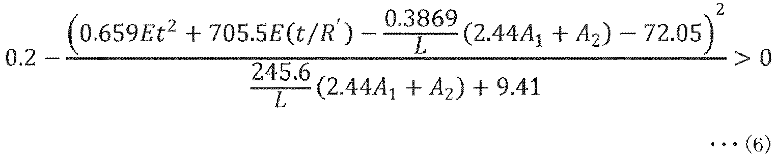 [Math. 12]
 here,R indicates a curvature radius (mm) of the curved portion,F indicates a length of a flat region having a flat shape in a first direction orthogonal to a bending axis of the curved portion when the cover glass is provided with the flat region adjacent to the curved portion in the first direction,t indicates a thickness (mm) of the cover glass,A1 indicates an area (mm2) of the first adhesive layer in the curved portion,A2 indicates an area (mm2) of the second adhesive layer in the curved portion,E indicates a Young's modulus (GPa) of the cover glass, andL indicates a length (mm) of the curved portion in the first direction.
 - The glass article according to any of claims 1 to 4, wherein
the flat region is provided on both sides of the curved portion in the first direction. - The glass article according to any of claims 1 to 5, wherein
(A1+A2)/L is 80 mm or less. - The glass article according to any of claims 1 to 6, wherein
the adhesive layer includes both the first adhesive layer and the second adhesive layer, and the first adhesive layer and the second adhesive layer are formed of different adhesive members. - The glass article according to any of claims 1 to 7, wherein
the cover glass has a thickness t of 0.3 mm or more and 3.0 mm or less. - The glass article according to any of claims 1 to 8, wherein
the curved portion has a curvature radius R of 50 mm or more and 10,000 mm or less. - The glass article according to any of claims 1 to 9, wherein
the cover glass has a Young's modulus E of 60 GPa or more and 90 GPa or less. - An on-vehicle display device comprising:a display; andthe glass article according to any of claims 1 to 10 provided on a surface of the display.
Applications Claiming Priority (3)
| Application Number | Priority Date | Filing Date | Title |
|---|---|---|---|
| JP2021139604 | 2021-08-30 | ||
| JP2022072684 | 2022-04-26 | ||
| PCT/JP2022/032462 WO2023032933A1 (en) | 2021-08-30 | 2022-08-29 | Glass article and onboard display device |
Publications (2)
| Publication Number | Publication Date |
|---|---|
| EP4397638A1 true EP4397638A1 (en) | 2024-07-10 |
| EP4397638A4 EP4397638A4 (en) | 2025-08-27 |
Family
ID=85412307
Family Applications (1)
| Application Number | Title | Priority Date | Filing Date |
|---|---|---|---|
| EP22864515.6A Pending EP4397638A4 (en) | 2021-08-30 | 2022-08-29 | GLASS ITEMS AND ON-BOARD DISPLAY DEVICE |
Country Status (6)
| Country | Link |
|---|---|
| US (1) | US12576714B2 (en) |
| EP (1) | EP4397638A4 (en) |
| JP (2) | JP7511119B2 (en) |
| CN (1) | CN119152773A (en) |
| TW (1) | TW202313378A (en) |
| WO (1) | WO2023032933A1 (en) |
Families Citing this family (1)
| Publication number | Priority date | Publication date | Assignee | Title |
|---|---|---|---|---|
| WO2025142928A1 (en) * | 2023-12-28 | 2025-07-03 | Agc株式会社 | Glass article, display device, method for manufacturing glass article, and method for manufacturing display device |
Family Cites Families (9)
| Publication number | Priority date | Publication date | Assignee | Title |
|---|---|---|---|---|
| KR102331876B1 (en) | 2014-07-10 | 2021-11-29 | 코닝 인코포레이티드 | Cold formed glass applique |
| JP7361705B2 (en) * | 2018-03-13 | 2023-10-16 | コーニング インコーポレイテッド | Vehicle interior system with crack-resistant curved cover glass and method of forming the same |
| EP3826877B1 (en) | 2018-07-26 | 2025-10-08 | Corning Incorporated | Cold-formed curved glass articles and methods of making the same |
| US20220001650A1 (en) | 2018-10-18 | 2022-01-06 | Corning Incorporated | Method of adhesive selection for cold forming product and process |
| KR20210097747A (en) | 2018-11-30 | 2021-08-09 | 코닝 인코포레이티드 | Cold-formed glass article having thermally matched system and process for forming same |
| JP7470533B2 (en) | 2020-03-09 | 2024-04-18 | 東芝ライフスタイル株式会社 | refrigerator |
| CN115485249A (en) * | 2020-04-30 | 2022-12-16 | Agc株式会社 | Glass, chemically strengthened glass, and electronic device |
| JP7720140B2 (en) | 2020-10-30 | 2025-08-07 | アキレス株式会社 | synthetic leather |
| WO2023127669A1 (en) * | 2021-12-27 | 2023-07-06 | Agc株式会社 | Glass, glass structure, and on-vehicle display device |
-
2022
- 2022-08-29 CN CN202411126542.3A patent/CN119152773A/en active Pending
- 2022-08-29 WO PCT/JP2022/032462 patent/WO2023032933A1/en not_active Ceased
- 2022-08-29 EP EP22864515.6A patent/EP4397638A4/en active Pending
- 2022-08-29 JP JP2023545571A patent/JP7511119B2/en active Active
- 2022-08-30 TW TW111132675A patent/TW202313378A/en unknown
-
2024
- 2024-02-23 US US18/585,364 patent/US12576714B2/en active Active
- 2024-06-03 JP JP2024089855A patent/JP2024116207A/en active Pending
Also Published As
| Publication number | Publication date |
|---|---|
| WO2023032933A1 (en) | 2023-03-09 |
| TW202313378A (en) | 2023-04-01 |
| JP7511119B2 (en) | 2024-07-05 |
| CN119152773A (en) | 2024-12-17 |
| US20240190248A1 (en) | 2024-06-13 |
| JP2024116207A (en) | 2024-08-27 |
| US12576714B2 (en) | 2026-03-17 |
| EP4397638A4 (en) | 2025-08-27 |
| JPWO2023032933A1 (en) | 2023-03-09 |
Similar Documents
| Publication | Publication Date | Title |
|---|---|---|
| CN103097315B (en) | Chemically strengthened glass, chemically strengthened glass, and glass plate for display devices | |
| KR102566346B1 (en) | Bendable glass articles with alkali-free glass elements | |
| KR102902309B1 (en) | Method for manufacturing tempered glass and tempered glass | |
| US20180215651A1 (en) | Chemically strengthened glass | |
| CN107207314A (en) | Curved surface cover glass, manufacturing method thereof, and vehicle-mounted display member | |
| TW202442434A (en) | Vehicle interior systems having a curved cover glass with improved impact performance and methods for forming the same | |
| US12576714B2 (en) | Glass article and onboard display device | |
| JP2022543442A (en) | Lamination method for automotive interiors with low bending stress and improved head model impact test performance | |
| JP2020536833A (en) | Pre-crushed glass composites and laminates with impact resistance, and methods for manufacturing them. | |
| EP4567008A1 (en) | Glass article, display device, method for manufacturing glass article, and method for manufacturing display device | |
| US20230312393A1 (en) | Tempered glass | |
| EP4428842A1 (en) | Display device | |
| TWI888622B (en) | Covering material and display device | |
| CN110824747B (en) | display device | |
| CN117940391B (en) | Glass products and vehicle-mounted display devices | |
| EP4321387A1 (en) | In-vehicle display device | |
| EP4458783A1 (en) | Glass, glass structure, and on-vehicle display device | |
| US20240206097A1 (en) | Display device | |
| JP2017109911A (en) | Cover glass for in-vehicle display devices | |
| EP4276082A1 (en) | Glass sheet, display device, and glass sheet manufacturing method | |
| US20240336513A1 (en) | Low-modulus ion-exchangeable glass compositions | |
| WO2025142928A1 (en) | Glass article, display device, method for manufacturing glass article, and method for manufacturing display device | |
| US20240010542A1 (en) | Magnetic bending frame for cold-forming thin glass sheet | |
| WO2025028349A1 (en) | Display device | |
| CN117897753A (en) | Display device |
Legal Events
| Date | Code | Title | Description |
|---|---|---|---|
| STAA | Information on the status of an ep patent application or granted ep patent |
Free format text: STATUS: THE INTERNATIONAL PUBLICATION HAS BEEN MADE |
|
| PUAI | Public reference made under article 153(3) epc to a published international application that has entered the european phase |
Free format text: ORIGINAL CODE: 0009012 |
|
| STAA | Information on the status of an ep patent application or granted ep patent |
Free format text: STATUS: REQUEST FOR EXAMINATION WAS MADE |
|
| 17P | Request for examination filed |
Effective date: 20240229 |
|
| AK | Designated contracting states |
Kind code of ref document: A1 Designated state(s): AL AT BE BG CH CY CZ DE DK EE ES FI FR GB GR HR HU IE IS IT LI LT LU LV MC MK MT NL NO PL PT RO RS SE SI SK SM TR |
|
| DAV | Request for validation of the european patent (deleted) | ||
| DAX | Request for extension of the european patent (deleted) | ||
| A4 | Supplementary search report drawn up and despatched |
Effective date: 20250725 |
|
| RIC1 | Information provided on ipc code assigned before grant |
Ipc: C03C 27/04 20060101AFI20250721BHEP Ipc: B32B 17/06 20060101ALI20250721BHEP Ipc: G09F 9/00 20060101ALI20250721BHEP Ipc: C03C 17/28 20060101ALI20250721BHEP Ipc: C03C 17/34 20060101ALI20250721BHEP |
|
| STAA | Information on the status of an ep patent application or granted ep patent |
Free format text: STATUS: EXAMINATION IS IN PROGRESS |
|
| 17Q | First examination report despatched |
Effective date: 20251105 |