EP4397607A1 - Slitter-winder and a method for slitting and winding a fiber web - Google Patents
Slitter-winder and a method for slitting and winding a fiber web Download PDFInfo
- Publication number
- EP4397607A1 EP4397607A1 EP23209631.3A EP23209631A EP4397607A1 EP 4397607 A1 EP4397607 A1 EP 4397607A1 EP 23209631 A EP23209631 A EP 23209631A EP 4397607 A1 EP4397607 A1 EP 4397607A1
- Authority
- EP
- European Patent Office
- Prior art keywords
- fiber web
- thick fiber
- winding
- winder
- slitter
- Prior art date
- Legal status (The legal status is an assumption and is not a legal conclusion. Google has not performed a legal analysis and makes no representation as to the accuracy of the status listed.)
- Granted
Links
Images




Classifications
-
- B—PERFORMING OPERATIONS; TRANSPORTING
- B65—CONVEYING; PACKING; STORING; HANDLING THIN OR FILAMENTARY MATERIAL
- B65H—HANDLING THIN OR FILAMENTARY MATERIAL, e.g. SHEETS, WEBS, CABLES
- B65H19/00—Changing the web roll
- B65H19/22—Changing the web roll in winding mechanisms or in connection with winding operations
- B65H19/2284—Simultaneous winding at several stations, e.g. slitter-rewinders
-
- B—PERFORMING OPERATIONS; TRANSPORTING
- B65—CONVEYING; PACKING; STORING; HANDLING THIN OR FILAMENTARY MATERIAL
- B65H—HANDLING THIN OR FILAMENTARY MATERIAL, e.g. SHEETS, WEBS, CABLES
- B65H19/00—Changing the web roll
- B65H19/10—Changing the web roll in unwinding mechanisms or in connection with unwinding operations
- B65H19/18—Attaching, e.g. pasting, the replacement web to the expiring web
-
- B—PERFORMING OPERATIONS; TRANSPORTING
- B26—HAND CUTTING TOOLS; CUTTING; SEVERING
- B26D—CUTTING; DETAILS COMMON TO MACHINES FOR PERFORATING, PUNCHING, CUTTING-OUT, STAMPING-OUT OR SEVERING
- B26D7/00—Details of apparatus for cutting, cutting-out, stamping-out, punching, perforating, or severing by means other than cutting
-
- B—PERFORMING OPERATIONS; TRANSPORTING
- B65—CONVEYING; PACKING; STORING; HANDLING THIN OR FILAMENTARY MATERIAL
- B65H—HANDLING THIN OR FILAMENTARY MATERIAL, e.g. SHEETS, WEBS, CABLES
- B65H19/00—Changing the web roll
- B65H19/10—Changing the web roll in unwinding mechanisms or in connection with unwinding operations
- B65H19/20—Cutting-off the expiring web
-
- B—PERFORMING OPERATIONS; TRANSPORTING
- B65—CONVEYING; PACKING; STORING; HANDLING THIN OR FILAMENTARY MATERIAL
- B65H—HANDLING THIN OR FILAMENTARY MATERIAL, e.g. SHEETS, WEBS, CABLES
- B65H2301/00—Handling processes for sheets or webs
- B65H2301/40—Type of handling process
- B65H2301/41—Winding, unwinding
- B65H2301/414—Winding
- B65H2301/4141—Preparing winding process
- B65H2301/41414—Preparing winding process involving pulper or doctor blade or air knife
-
- B—PERFORMING OPERATIONS; TRANSPORTING
- B65—CONVEYING; PACKING; STORING; HANDLING THIN OR FILAMENTARY MATERIAL
- B65H—HANDLING THIN OR FILAMENTARY MATERIAL, e.g. SHEETS, WEBS, CABLES
- B65H2301/00—Handling processes for sheets or webs
- B65H2301/40—Type of handling process
- B65H2301/41—Winding, unwinding
- B65H2301/414—Winding
- B65H2301/4148—Winding slitting
-
- B—PERFORMING OPERATIONS; TRANSPORTING
- B65—CONVEYING; PACKING; STORING; HANDLING THIN OR FILAMENTARY MATERIAL
- B65H—HANDLING THIN OR FILAMENTARY MATERIAL, e.g. SHEETS, WEBS, CABLES
- B65H2301/00—Handling processes for sheets or webs
- B65H2301/40—Type of handling process
- B65H2301/46—Splicing
- B65H2301/4601—Splicing special splicing features or applications
- B65H2301/46011—Splicing special splicing features or applications in winding process
-
- B—PERFORMING OPERATIONS; TRANSPORTING
- B65—CONVEYING; PACKING; STORING; HANDLING THIN OR FILAMENTARY MATERIAL
- B65H—HANDLING THIN OR FILAMENTARY MATERIAL, e.g. SHEETS, WEBS, CABLES
- B65H2301/00—Handling processes for sheets or webs
- B65H2301/40—Type of handling process
- B65H2301/46—Splicing
- B65H2301/461—Processing webs in splicing process
- B65H2301/4615—Processing webs in splicing process after splicing
- B65H2301/4617—Processing webs in splicing process after splicing cutting webs in splicing process
-
- B—PERFORMING OPERATIONS; TRANSPORTING
- B65—CONVEYING; PACKING; STORING; HANDLING THIN OR FILAMENTARY MATERIAL
- B65H—HANDLING THIN OR FILAMENTARY MATERIAL, e.g. SHEETS, WEBS, CABLES
- B65H2301/00—Handling processes for sheets or webs
- B65H2301/50—Auxiliary process performed during handling process
- B65H2301/51—Modifying a characteristic of handled material
- B65H2301/515—Cutting handled material
- B65H2301/5155—Cutting handled material longitudinally
Definitions
- the finished fiber web being output from the fiber web production line is wound with a reel-up around a reeling shaft, i.e. a reel spool, into a parent roll (a machine roll).
- the purpose of the reeling is to transfer the fiber web from its planar manufacturing form into a form in which it can be handled more easily.
- the reel-up is thus a device that reels a material, which is produced as a continuous fiber web in a fiber web production line, into form of a roll; the parent roll.
- the reeling is generally a first process part, wherein a continuous process is discontinued to be continued in sequences.
- the parent roll is formed around the reeling shaft that functions as a core of reeling, i.e. the fiber web on one parent roll around one reeling shaft has a beginning end and an end.
- the parent roll is unwound in an unwinding station of the unwinding section off the reeling shaft and the fiber web is slit with slitting blades of the slitting section into a number of narrower partial webs, which are wound in a winder of the winding section around winding spools such as cores into the customer rolls.
- the slitter-winder is stopped and the rolls, or "set", is removed from the machine. After this, the process continues with the winding of a new set. These stages are repeated periodically.
- the unwinding section comprises only one unwinder the stages are repeated until the fiber web on the parent roll runs out from the reeling shaft, at which point the parent roll is replaced, the end of the fiber web from the emptying parent roll is joined to the beginning end of the fiber web from a new parent roll, emptying and the operation restarts with the unwinding of a new parent roll from the reeling shaft.
- the parent roll change in the unwinder is typically slow due to challenges caused by the thick fiber web. Typically it takes even ten minutes.
- the slitting and winding process is a cyclic process, wherein the process is in the beginning accelerated to a set running speed and when a set of customer rolls is about to be finished the process is decelerated to be stopped for the set change.
- the finished set of the customer rolls is removed from the winder of the slitter-winder and new cores for winding the next set of the customer rolls are fed to the winder.
- capacity of a slitter-winder is dependent on sequence times of the slitter-winder, especially on the stopping time, and on the running speed of the slitter-winder.
- the slitting section of the slitter-winder comprises slitting blades for slitting the full-width thick fiber web in longitudinal direction of the thick fiber web to partial thick fiber webs
- the winding section of the slitter-winder comprises at least one winding drum for winding the partial thick fiber webs to customer rolls
- the winding section of the slitter-winder a cutting device for cutting the partial thick fiber webs when a set of the customer rolls is finished and the cutting device is also configured to cut the partial thick fiber webs when a set of the customer rolls is finished.
- the slitting section of the slitter-winder comprises slitting blades for slitting the full-width thick fiber web in longitudinal direction of the thick fiber web to partial thick fiber webs
- the winding section of the slitter-winder comprises at least one winding drum for winding the partial thick fiber webs to customer rolls
- the slitting section comprises an additional cutting device configured to cut the partial thick fiber webs when a set of the customer rolls is finished.
- the part/- s of the thick fiber web with the joint is/are guided through the winding section towards a reject handling system.
- the part/-s of the thick fiber web of the partial thick fiber webs with the joint is/are guided through the winding section over the at least one winding drum.
- the joint is removed from the thick fiber web in the winding section of the slitter-winder before the beginning ends of the slitted partial fiber webs are guided to be wound to the customer rolls.
- the joints are not present in the finished customer rolls.
- the set change is interrupted after the customer rolls have been removed from the winder before the cores for the next customer roll set winding are placed in the slitter-winder.
- the cores for the next customer roll set winding are placed in the slitter-winder after the part of the thick fiber web with the joint has been removed.
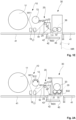
- FIGS 1A-1E is shown schematically an advantageous example of a slitter-winder and a method for slitting and winding a thick fiber web.
- the part/-s with the joint J is/are removed before starting of winding of the next set of the customer rolls by a cutting device 35 located between the two winding drums 31, 32 and after the finished customer rolls 33 have been pushed off from the winder.
- FIGS 2A-2E is shown schematically another advantageous example of a slitter-winder and a method for slitting and winding a thick fiber web.
- the partial thick fiber webs W20 are guided to the winder around the front winding drum 32.
- the part/-s with the joint J W20 is/are removed, before starting of winding of the next set of the customer rolls, by a cutting device 35 located in front of the front winding drum 32 and after the finished customer rolls 33 have been pushed off from the winder.
- FIGS 3A-3D is shown schematically yet another advantageous example of a slitter-winder and a method for slitting and winding a thick fiber web.
- the partial thick fiber webs W20 are guided to the winder between the two winding drums 31, 32 or around the front winding drum 32.
- the part/- s with the joint J is/are removed, before starting of winding of the next set of the customer rolls, by a cutting device 35 located below the winding drums 31, 32 and after the finished customer rolls 33 have been pushed off from the winder.
- a slitter-winder for fiber webs which comprises an unwinding section 10, a slitting section 20 and a winding section 30.
- the slitter-winder is configured to unwind, slit and wind a thick fiber web basic weight of at least 200 g/m 2 to customer rolls 33.
- the unwinding section 10 of the slitter-winder comprises two unwinders: a first unwinder 11 and a second unwinder 12 for unwinding the thick fiber web of from a parent roll comprising full-width thick fiber web W11, W12.
- the unwinding section 10 further comprises a joining device 16, 17 for joining a beginning end of a thick fiber web W11 coming from a parent roll in the first unwinder to an end of a thick fiber web W12 coming from a parent roll in the second unwinder by forming a joint J.
- the winding section 30 of the slitter-winder a cutting device 35 for cutting and removing part/-s of the thick fiber web comprising the joint J from the winding section 30.
- the slitting section 20 of the slitter-winder comprises slitting blades 21, 22 for slitting the full-width thick fiber web W11; W12 in longitudinal direction of the thick fiber web to partial thick fiber webs W20.
- the winding section 30 of the slitter-winder comprises at least one winding drum 31; 32 for winding the partial thick fiber webs W20 to customer rolls 33 and the cutting device 35 is also configured to cut the partial thick fiber webs when a set of the customer rolls 33 is finished or the slitting section 20 comprises an additional cutting device configured to cut the partial thick fiber webs when a set of the customer rolls 33 is finished.
- the cutting device 35 is a full width cutting blade or a traversing fixed or rotating blade.
- the cutting device 35 may also be a scoring device for weakening the thick fiber web at the cutting location and the actual cutting is provided by tension, blowing or as such by one skilled in the art known manner.
- the slitter-winder comprises a reject handling system configured to receive the cut part/-s comprising the joint J removed from the thick fiber web or from the partial thick fiber webs W.
- the joining device 16,17 is advantageously configured to form a form-fitting joint J.
- a full-width thick fiber web W11, W12 is unwound is the unwinding section 10
- the full-width thick fiber web W11, W12 is alternating unwound in the unwinding section 10 from a parent roll in a first unwinder 11 and from a parent roll in a second unwinder 12.
- part/-s of the thick fiber web comprising the joint J are cut by the cutting device 35 and removed from the winding section 30 automatically.
- the part/-s of the thick fiber web comprising the joint J is/are guided through the winding section 30 towards a reject handling system over the at least one winding drum 31; 32, as the part/-s comprising the joint J is/are cut by the cutting device 35 and removed from the thick fiber web or the partial thick fiber webs Wto the reject handling system through reject opening 45 or by the reject conveyor.
- the method comprises stages of a. finishing winding of a finished customer roll set and removing the finished customer roll set from the winder, b.
- FIGS 1A-1E is shown an example of a slitter-winder and a method for slitting and winding a thick fiber web.
- the slitter-winder comprises an unwinding section 10, a slitting section 20 and a winding section 30.
- the unwinding section 10 comprises two unwinders 11, 12, a first unwinder 11 and a second unwinder 12, for alternating unwinding a parent roll of full-width thick fiber web W11 coming from the first unwinder and a parent roll of full-width thick fiber web W12 coming from the second unwinder 12.
- the slitter-winder also comprises a joining device 16, 17 for joining the end of the thick fiber web coming from the emptying parent roll in the second unwinder 12 to the beginning end of the thick fiber web coming from the parent roll to be unwound in the first unwinder 11.
- a joint is formed to attach the beginning end of a second thick fiber web unwinding from one parent roll to the end of the thick fiber web coming from another parent roll.
- the joint is advantageously a form-fitting joint.
- the slitting section 20 comprises a guide roll 23 to guide the thick fiber web W between the slitting blades 21,22, which slit the thick fiber wet W in longitudinal direction to partial thick fiber webs W20, which have desired widths.
- FIG 1A the method for slitting and winding a thick fiber web in the slitter-winder is in a stage, in which the thick fiber web W12 is still running therefrom through the slitting section 20 from the parent roll in the second unwinder 12 is running via the slitting section 20 and after slitting the partial thick fiber webs W20 are running to the unwinding section 30 and the customer roll set 33 in the winder of the winding section is under winding.
- the thick fiber web W12 runs via the front part 17 of the joining device 16, 17.
- FIG 1B the method for slitting and winding a thick fiber web in the slitter-winder is in a stage, in which the parent roll in the second unwinder 12 in the unwinding section 10 is almost empty but the thick fiber web W12 is still running therefrom through the slitting section 20 to the unwinding section 30 and the customer roll set 33 in the winder of the winding section is almost finished.
- the thick fiber web W12 runs via the front part 17 of the joining device 16, 17 and the thick fiber web W11 is attached to the back part 16 of the joining device 16, 17, and thus, the joining device 16, 17 is in position of readiness.
- Rotation direction of the second unwinder 12 is denoted by an arrow S12 and rotation directions of the winding drums 31, 32 are denoted by arrows S31, 32.
- the method for slitting and winding a thick fiber web in the slitter-winder is in a stage, in which the slitter-winder is slowed down to a crawling speed or to a stop.
- the joint is formed to attach the beginning end of a second thick fiber web unwinding from the new parent roll coming from the first unwinder 11 to the end of the thick fiber web coming from emptying parent roll in the second unwinder 12 by the joining device 16, 17.
- the advantageous form-fitting joint can be formed by pressing the beginning end and the end between the front part 17 and the back part 16 of the joining device 16, 17 together.
- One of the parts 16; 17 may have cutting elements for forming a joining cut and the other part 17 has a counter part to the cutting elements.
- the full-width thick fiber web running from the second unwinder 12 is cut.
- the partial thick fiber webs W20 running to form the customer roll set 33 are cut by the cutting device 35 and simultaneously the finished customer roll set 33 is removed from the winder of the winding section 30 by a pusher 34.
- the slitter-winder also comprises a joining device 16, 17 for joining the end of the thick fiber web coming from the emptying parent roll in the second unwinder 12 to the beginning end of the thick fiber web coming from the parent roll to be unwound in the first unwinder 11.
- a joining device 16, 17 By the joining device 16, 17 a joint is formed to attach the beginning end of a second thick fiber web unwinding from one parent roll to the end of the thick fiber web coming from another parent roll.
- the joint is advantageously a form-fitting joint, for example as described in applicants' EP patent application.
- the method for slitting and winding a thick fiber web in the slitter-winder is in a stage, in which the slitter-winder is slowed down to a crawling speed or to a stop.
- the joint is formed to attach the beginning end of a second thick fiber web unwinding from the new parent roll coming from the first unwinder 11 to the end of the thick fiber web coming from emptying parent roll in the second unwinder 12 by the joining device 16, 17.
- the advantageous form-fitting joint can be formed by pressing the beginning end and the end between the front part 17 and the back part 16 of the joining device 16, 17 together.
- the method for slitting and winding a thick fiber web in the slitter-winder is in a stage, in which the slitter-winder is still slowed down to the crawling speed or at the stop.
- the unwinding has been changed to the first unwinder 11 and thus, to the new parent roll and the thick fiber web W11 with the joint J runs through the slitting section 20, in which the slitting blades 21, 22 are advantageously in a non-cutting position but they can also be in a cutting position, to the winding section 30 and is guided as the reject fiber web towards the reject handling system via the reject opening 45 or by a reject conveyor.
- the part/-s with the joint J is/are guided via the reject opening 45 or by the reject conveyor to the reject handling system.
- the slitter-winder also comprises a joining device 16, 17 for joining the end of the thick fiber web coming from the emptying parent roll in the second unwinder 12 to the beginning end of the thick fiber web coming from the parent roll to be unwound in the first unwinder 11.
- a joining device 16, 17 By the joining device 16, 17 a joint is formed to attach the beginning end of a second thick fiber web unwinding from one parent roll to the end of the thick fiber web coming from another parent roll.
- the joint is advantageously a form-fitting joint, for example as described in applicants' EP patent application.
- the winding section 30 also comprises a cutting device 35 which is located below the winding drums 32, for cutting the joint end of the thick fiber web W20
- the cutting device 35 can also be used for cutting the partial thick fiber webs during a set-change or the winding section can comprise an additional cutting device for cutting the partial thick fiber webs during the set-change.
- the winding section 30 also comprises a pusher 34 for removing the finished customer roll set 33 from the winder.
- the winding section 30 may also comprise a blowing means for assisting the guiding of the part/-s with the joint J towards the reject opening 45 or the reject conveyor.
- the slitter-winder is located on the floor level 41, which may comprise an offset floor level part 42, which in this example is located partially under the slitting section 20 and under the winding section.
- the method for slitting and winding a thick fiber web in the slitter-winder is in a stage, in which the thick fiber web W12 is still running therefrom through the slitting section 20 from the parent roll in the second unwinder 12 is running via the slitting section 20 and after slitting the partial thick fiber webs W20 are running to the unwinding section 30 and the customer roll set 33 in the winder of the winding section is under winding.
- the thick fiber web W12 runs via the front part 17 of the joining device 16, 17.
- the method for slitting and winding a thick fiber web in the slitter-winder is in a stage, in which the slitter-winder is still slowed down to the crawling speed or at the stop.
- the reject fiber web WR is cut by the cutting device 35 and the beginning end of the partial thick fiber webs W20 are guided between the winding drums 31, 32 and winding cores 36 placed on support of the winding drums 31, 32, while the back winding drum 31 is rotated, as shown by an arrow S31.
- the slitter-winder is accelerated to the operating, running speed and the slitting and winding a new customer roll set begins.
Landscapes
- Life Sciences & Earth Sciences (AREA)
- Forests & Forestry (AREA)
- Engineering & Computer Science (AREA)
- Mechanical Engineering (AREA)
- Replacement Of Web Rolls (AREA)
Abstract
Description
- In general, present invention relates to production of fiber webs, in particular to producing of thick fiber webs such as pulp webs. More especially the present invention relates to according to preamble part of the independent slitter-winder claim and to a method for slitting and winding a fiber web according to preamble part of the independent method claim.
- As known, fiber webs, also thick fiber webs, are manufactured in machines together forming a fiber web manufacturing line, which may be hundreds of meters long. Fiber webs, especially paper and board are available in a wide variety of types and can be divided according to basis weight in two grades: papers with a single ply and a basis weight of 25-300 g/m2 and boards manufactured in one- or multi-ply technology and having a basis weight of 150-600 m/m2. It should be noted that the borderline between paper and board is flexible since board grades with lightest basis weights are lighter than the heaviest paper grades. Generally speaking, paper is used for printing and board for packaging. Thick fiber webs are generally considered to comprise pulp webs and thick board webs. Density of a pulp web is about 400 - 800 kg/m3 and thickness of the pulp web is about 0,5 - 2,5 mm. Thick board webs have typically thickness of at least 0,3 mm.
- In fiber web production lines, manufacturing operates as a continuous process. The finished fiber web being output from the fiber web production line is wound with a reel-up around a reeling shaft, i.e. a reel spool, into a parent roll (a machine roll). The purpose of the reeling is to transfer the fiber web from its planar manufacturing form into a form in which it can be handled more easily. The reel-up is thus a device that reels a material, which is produced as a continuous fiber web in a fiber web production line, into form of a roll; the parent roll. In the production process of the fiber web, the reeling is generally a first process part, wherein a continuous process is discontinued to be continued in sequences. The parent roll is formed around the reeling shaft that functions as a core of reeling, i.e. the fiber web on one parent roll around one reeling shaft has a beginning end and an end.
- The fiber web of the parent roll generated during manufacture is full-width and long, so it must be slit and cut into partial webs of a suitable width and length for customers and wound around cores into "customer rolls" before dispatch to customers. As known, this slitting and winding of the web takes place in a separate machine fitted to the purpose, i.e., in a slitter-winder, which comprises an unwinding section, a slitting section and a winding section. In the slitter-winder the parent roll is unwound in an unwinding station of the unwinding section off the reeling shaft and the fiber web is slit with slitting blades of the slitting section into a number of narrower partial webs, which are wound in a winder of the winding section around winding spools such as cores into the customer rolls. When the customer rolls are ready, the slitter-winder is stopped and the rolls, or "set", is removed from the machine. After this, the process continues with the winding of a new set. These stages are repeated periodically. In cases the unwinding section comprises only one unwinder the stages are repeated until the fiber web on the parent roll runs out from the reeling shaft, at which point the parent roll is replaced, the end of the fiber web from the emptying parent roll is joined to the beginning end of the fiber web from a new parent roll, emptying and the operation restarts with the unwinding of a new parent roll from the reeling shaft. In unwinders of slitter-winders for thick fiber webs the parent roll change in the unwinder is typically slow due to challenges caused by the thick fiber web. Typically it takes even ten minutes.
- The joining of the end of the parent roll to the beginning end of the next parent roll creates a joint to the fiber web to be further processed in the slitter-winder to the customer rolls. In connection with thick fiber webs it has been difficult to find a functional joining method. For example using of adhesive tapes has proven disadvantageous, as the tapes may peel of fibers from the surface of the thick fiber webs. At the present most promising joining method has turned out to be a form fitting joint. But these joints are thicker than the rest of the fiber web and thus, these joints are not welcome in the customer rolls as they may cause problems in the end processing of the thick fiber web obtained from the customer rolls to end products at customer sites. It is known from prior art to run the slitting and winding process such that the joint is located in bottom layers of the customer roll, but this has caused vibration problems in further processing of the customer rolls. It is also known from prior art to run the slitting and winding process such that the joint is located on outer layer of the customer roll, but this has proven difficult as the process is fast and there is not time to manually remove the joint.
- The slitting and winding process is a cyclic process, wherein the process is in the beginning accelerated to a set running speed and when a set of customer rolls is about to be finished the process is decelerated to be stopped for the set change. The finished set of the customer rolls is removed from the winder of the slitter-winder and new cores for winding the next set of the customer rolls are fed to the winder. Thus, capacity of a slitter-winder is dependent on sequence times of the slitter-winder, especially on the stopping time, and on the running speed of the slitter-winder.
- Slitter-winders employ winding devices of different types, for example multistation winders and two-drum winders. In the two-drum winders the partial webs are wound around winding cores supported by two winding drums to partial web rolls via a nip between the winding drums and the partial pulp web rolls being formed. In the two-drum winders also a belt arrangement i.e. a so-called set of belt rolls with belt loop or belt loops located around two guide rolls can be used as the winding drum. As known in the prior art, also winding with a shaft without cores or together with cores can be employed in the winding of a pulp web into customer rolls on a slitter-winder.
- In patent application publication
WO2010052373A1 is disclosed a method associated with a slitter winder for a fiber web, according to which method a web slit in the slitting section of a slitter winder into partial webs is rewound into partial rolls having a certain diameter and according to which method the machine roll to be unwound is unwound in the primary unwinding station by a drive connected to the machine roll down to a certain diameter and the machine roll is removed from the primary unwinding station. During the transfer the tension of the web is at least partly controlled by a drive and/or by means of a brake of the transfer means of the unwinding apparatus, and after the transfer a new machine roll is brought to the primary unwinding station and the end of the web of the new machine roll is taken to the vicinity of the splicing apparatus while the unwinding from the old machine roll is in progress. - In patent application publication
WO2010000944A2 is disclosed an unwinding arrangement of a fiber web for unwinding the fibrous web wound on a winding shaft, which comprises two substantially parallel rails or equivalents arranged at a distance from each other for supporting the winding shaft and an unwinding station in connection with the rails, which unwinding station comprises elements for locking the winding shaft on the unwinding station to be substantially stationary during unwinding. - An object of the invention is to create a slitter-winder for thick fiber webs and a method for slitting and winding a thick fiber web, in which the disadvantages and problems of prior art are eliminated or at least minimized.
- An object of the invention is to create a slitter-winder for thick fiber webs and a method for slitting and winding a thick fiber web, in which the problems relating to the long parent roll changes are eliminated or at least minimized.
- An object of the invention is to create a slitter-winder for thick fiber webs and a method for slitting and winding a thick fiber web, in which the problems relating to the joints are eliminated or at least minimized.
- In order to achieve the above-mentioned objects, the slitter-winder according to the invention is mainly characterized by the features of the characterizing clause of the independent slitter-winder claim. In turn, the method of slitting and winding a fiber web according to the invention is mainly characterized by the features of the characterizing clause of the independent method claim. Advantageous embodiments and features are disclosed in the dependent claims.
- In this description and in the claims by the term "thick fiber web" is meant a fiber web that has basis weight of at least 200 g/m2. The present invention relates to production of the thick fiber webs and it is especially suitable in connection of production of the pulp webs, as well as thick board webs, such as folding boxboards and liquid packaging boards. The winding drum can also be a belt arrangement i.e. a so-called set of belt rolls with belt loop or belt loops located around two guide rolls.
- According to the invention the slitter-winder for fiber webs comprises an unwinding section, a slitting section and a winding section, and the slitter-winder is configured to unwind, slit and wind a thick fiber web to customer rolls, the thick fiber web has basic weight of at least 200 g/m2 , the unwinding section of the slitter-winder comprises a first unwinder and a second unwinder for unwinding the thick fiber web of from a parent roll comprising full-width thick fiber web, and a joining device for joining a beginning end of a thick fiber web coming from a parent roll in the first unwinder to an end of a thick fiber web coming from a parent roll in the second unwinder by forming a joint, and the winding section of the slitter-winder comprises a cutting device for cutting and removing part/-s of the thick fiber web comprising the joint from the winding section.
- According to an advantageous feature of the invention in the slitter-winder the slitting section of the slitter-winder comprises slitting blades for slitting the full-width thick fiber web in longitudinal direction of the thick fiber web to partial thick fiber webs, the winding section of the slitter-winder comprises at least one winding drum for winding the partial thick fiber webs to customer rolls, and the winding section of the slitter-winder a cutting device for cutting the partial thick fiber webs when a set of the customer rolls is finished and the cutting device is also configured to cut the partial thick fiber webs when a set of the customer rolls is finished.
- According to an advantageous feature of the invention the slitting section of the slitter-winder comprises slitting blades for slitting the full-width thick fiber web in longitudinal direction of the thick fiber web to partial thick fiber webs, the winding section of the slitter-winder comprises at least one winding drum for winding the partial thick fiber webs to customer rolls and the slitting section comprises an additional cutting device configured to cut the partial thick fiber webs when a set of the customer rolls is finished.
- According to an advantageous feature of the invention the slitter-winder comprises a reject handling system configured to receive the cut part/-s comprising the joint removed from the thick fiber webs.
- According to an advantageous feature of the invention the winding section comprises a two drum winder comprising a front winding drum and a back winding drum and that the cutting device is located between the front winding drum and the back winding drum.
- According to an advantageous feature of the invention the winding section comprises a two drum winder comprising a front winding drum and a back winding drum and that the cutting device is located below the front winding drum and the back winding drum.
- According to an advantageous feature of the invention the winding section comprises a two drum winder comprising a front winding drum and a back winding drum and that the cutting device is located in front of the front winding drum.
- According to an advantageous feature of the invention the joining device is configured to form a form-fitting joint.
- According to the invention in the method of slitting and winding a fiber web in a slitter-winder comprising an unwinding section, a slitting section and a winding section, a full-width thick fiber web is unwound is the unwinding section,
- the thick fiber web has basic weight of at least 200 g/m2 ,
- in the method the full-width thick fiber web is alternating unwound in the unwinding section from a parent roll in a first unwinder and from a parent roll in a second unwinder,
- in the method a beginning end of a thick fiber web coming from the parent roll in the first unwinder to an end of a thick fiber web coming from the parent roll in the second unwinder by a joining device forming a joint between the beginning end and the end,
- and in the method part/-s comprising the joint are cut by the cutting device and removed from winding section automatically.
- According to an advantageous feature of the invention in the method the fiber web slitted in longitudinal direction of the thick fiber web to partial thick fiber webs and the partial thick fiber webs are wound to customer rolls in the winding section, which comprises at least one winding drum and in the method the partial thick fiber webs are cut by the cutting device or by an additional cutting device, when a set of the customer rolls is finished
- According to an advantageous feature of the invention in the method the part/- s of the thick fiber web with the joint is/are guided through the winding section towards a reject handling system.
- According to an advantageous feature of the invention the part/-s comprising the joint is/are cut by the cutting device and removed from the thick fiber web of the partial thick fiber webs to the reject handling system through a reject opening or by a reject conveyor.
- According to an advantageous feature of the invention the in the method the part/-s of the thick fiber web of the partial thick fiber webs with the joint is/are guided through the winding section over the at least one winding drum.
- According to an advantageous feature of the invention the method comprises stages of a. finishing winding of a finished customer roll set and removing the finished customer roll set from the winder, b. changing the unwinding from emptying parent roll in one unwinder to a new parent roll in the other unwinder and joining the fiber web ends, c. preparing the winder for next customer roll set winding, and d. beginning steps for the winding of the new customer rolls step.
- According to an advantageous feature of the invention in the method stages a. finishing winding of a finished customer roll set and removing the finished customer roll set from the winder and b. changing the unwinding from emptying parent roll in one unwinder to a new parent roll in the other unwinder and joining the fiber web ends are performed simultaneously.
- According to an advantageous feature of the invention in the method before stage a. finishing winding of a finished customer roll set and removing the finished customer roll set from the winder the slitter-winder is decelerated to crawling speed or to a stop.
- According to an advantageous feature of the invention in the method after the stage d. beginning steps for the winding of the new customer rolls step the slitter-winder is accelerated to a running speed.
- According to an advantageous feature of the invention in the method the fiber web is jogged, i.e. run at a lower (crawling) speed than the running speed, forward between the cutting for finishing the customer rolls and the cutting of the part/-s of the thick fiber web comprising the joint for removing the part/-s of the thick fiber web comprising the joint.
- According to an advantageous aspect of the invention in the slitter-winder for thick fiber webs and in the method of slitting and winding a thick fiber web, in the unwinding section has two unwinders in order to keep the supply of the thick fiber web for the slitting and the winding last longer and to decrease the capacity loss of the stopping times. When a parent roll unwound on a first unwinder is almost empty, end of the fiber web coming from the parent roll on the first unwinder is joined to the beginning end of the fiber web coming from a parent roll on a second unwinder by a joining device based on a form-fitting joint creating technique. The unwinding is changed to the second unwinder and a new parent roll is moved to the first unwinder. When the parent roll unwound on the second unwinder is almost empty, end of the fiber web coming from the parent roll on the second unwinder is joined to the beginning end of the fiber web coming from the new parent roll on the first unwinder. These stages are repeated until the required customer rolls have been produced.
- According to an advantageous aspect of the invention in the method the joining of the fiber web ends in the unwinding section and the set change in the winding section are performed at least partially simultaneously.
- According to an advantageous aspect of the invention the joint is removed from the thick fiber web in the winding section of the slitter-winder before the beginning ends of the slitted partial fiber webs are guided to be wound to the customer rolls. Thus, the joints are not present in the finished customer rolls.
- According to an advantageous aspect of the invention in the method the joint is guided via the winding section towards a pulper or other reject handing of the fiber web production line and thereafter the thick fiber web is cut such that the part of the thick fiber web with the joint is guided to the pulper or the reject handling and the new end of the thick fiber is guided to winding of the customer rolls.
- According to an advantageous aspect of the invention as the cutting device cutting the part of the thick fiber web with the joint is utilized the cutting device of the slitter-winder used for cutting the partial fiber webs. Advantageously, a blowing device may be utilized for helping guidance of the part of the thick fiber web with the joint.
- According to an advantageous aspect of the invention in the method the set change is interrupted after the customer rolls have been removed from the winder before the cores for the next customer roll set winding are placed in the slitter-winder. Advantageously, the cores for the next customer roll set winding are placed in the slitter-winder after the part of the thick fiber web with the joint has been removed.
- By the invention and its advantageous features many advantages are achieved: The change time of the parent roll in the unwinding section is reduced to less than two minutes, which improves the capacity of the slitter-winder for thick fiber webs significantly, even 30-40%. This also provides the possibility of using higher running speed at a board machine or at a pulp dryer. Additionally, the customer rolls are provided to the customers without joints, which improves the production of the end products at the customer site. One of the main advantages is also, that no manual removal of joints is needed. Further, stability of winding of the customer rolls in the winding section is improved in cases, where form-fitting joints are use as the joints do not function as impulse for possible vibration.
- In the following the invention is explained in detail with reference to the accompanying drawing to which the invention is not to be narrowly limited.
- In
figures 1A-1E is shown schematically an advantageous example of a slitter-winder and a method for slitting and winding a thick fiber web. In this example The part/-s with the joint J is/are removed before starting of winding of the next set of the customer rolls by a cuttingdevice 35 located between the two windingdrums - In
figures 2A-2E is shown schematically another advantageous example of a slitter-winder and a method for slitting and winding a thick fiber web. In this example the partial thick fiber webs W20 are guided to the winder around thefront winding drum 32. The part/-s with the joint J W20 is/are removed, before starting of winding of the next set of the customer rolls, by a cuttingdevice 35 located in front of the front windingdrum 32 and after the finished customer rolls 33 have been pushed off from the winder. - In
figures 3A-3D is shown schematically yet another advantageous example of a slitter-winder and a method for slitting and winding a thick fiber web. In this example the partial thick fiber webs W20 are guided to the winder between the two windingdrums front winding drum 32. The part/- s with the joint J is/are removed, before starting of winding of the next set of the customer rolls, by a cuttingdevice 35 located below the windingdrums - During the course of the following description like numbers and signs will be used to identify like elements according to the different views which illustrate the invention and its advantageous examples. In the figures some repetitive reference signs have been omitted for clarity reasons.
- In the examples of the figures is schematically shown a slitter-winder for fiber webs, which comprises an unwinding
section 10, aslitting section 20 and a windingsection 30. The slitter-winder is configured to unwind, slit and wind a thick fiber web basic weight of at least 200 g/m2 to customer rolls 33. The unwindingsection 10 of the slitter-winder comprises two unwinders: afirst unwinder 11 and asecond unwinder 12 for unwinding the thick fiber web of from a parent roll comprising full-width thick fiber web W11, W12. The unwindingsection 10 further comprises a joiningdevice section 30 of the slitter-winder acutting device 35 for cutting and removing part/-s of the thick fiber web comprising the joint J from the windingsection 30. - The slitting
section 20 of the slitter-winder comprises slitting blades 21, 22 for slitting the full-width thick fiber web W11; W12 in longitudinal direction of the thick fiber web to partial thick fiber webs W20. The windingsection 30 of the slitter-winder comprises at least one windingdrum 31; 32 for winding the partial thick fiber webs W20 to customer rolls 33 and thecutting device 35 is also configured to cut the partial thick fiber webs when a set of the customer rolls 33 is finished or theslitting section 20 comprises an additional cutting device configured to cut the partial thick fiber webs when a set of the customer rolls 33 is finished. The cuttingdevice 35 is a full width cutting blade or a traversing fixed or rotating blade. The cuttingdevice 35 may also be a scoring device for weakening the thick fiber web at the cutting location and the actual cutting is provided by tension, blowing or as such by one skilled in the art known manner. The slitter-winder comprises a reject handling system configured to receive the cut part/-s comprising the joint J removed from the thick fiber web or from the partial thick fiber webs W. The joiningdevice section 10, and the full-width thick fiber web W11, W12 is alternating unwound in the unwindingsection 10 from a parent roll in afirst unwinder 11 and from a parent roll in asecond unwinder 12. In the method a beginning end of a thick fiber web W11 coming from the parent roll in the first unwinder to an end of a thick fiber web W12 coming from the parent roll in the second unwinder by a joiningdevice device 35 and removed from the windingsection 30 automatically. In the method the part/-s of the thick fiber web comprising the joint J is/are guided through the windingsection 30 towards a reject handling system over the at least one windingdrum 31; 32, as the part/-s comprising the joint J is/are cut by the cuttingdevice 35 and removed from the thick fiber web or the partial thick fiber webs Wto the reject handling system through reject opening 45 or by the reject conveyor. Thus, the method comprises stages of a. finishing winding of a finished customer roll set and removing the finished customer roll set from the winder, b. changing the unwinding from emptying parent roll in one unwinder to a new parent roll in the other unwinder and joining the fiber web ends, c. preparing the winder for next customer roll set winding, and d. beginning steps for the winding of the new customer rolls step. In the method stages a. finishing winding of a finished customer roll set and removing the finished customer roll set from the winder and b. changing the unwinding from emptying parent roll in one unwinder to a new parent roll in the other unwinder and joining the fiber web ends are performed simultaneously. In the method before stage a. finishing winding of a finished customer roll set and removing the finished customer roll set from the winder the slitter-winder is decelerated to crawling speed or to a stop. In the method after the stage d. beginning steps for the winding of the new customer rolls step the slitter-winder is accelerated to a running speed. - In
figures 1A-1E is shown an example of a slitter-winder and a method for slitting and winding a thick fiber web. The slitter-winder comprises an unwindingsection 10, aslitting section 20 and a windingsection 30. The unwindingsection 10 comprises twounwinders first unwinder 11 and asecond unwinder 12, for alternating unwinding a parent roll of full-width thick fiber web W11 coming from the first unwinder and a parent roll of full-width thick fiber web W12 coming from thesecond unwinder 12. The slitter-winder also comprises a joiningdevice second unwinder 12 to the beginning end of the thick fiber web coming from the parent roll to be unwound in thefirst unwinder 11. By the joiningdevice 16, 17 a joint is formed to attach the beginning end of a second thick fiber web unwinding from one parent roll to the end of the thick fiber web coming from another parent roll. The joint is advantageously a form-fitting joint. The slittingsection 20 comprises aguide roll 23 to guide the thick fiber web W between the slitting blades 21,22, which slit the thick fiber wet W in longitudinal direction to partial thick fiber webs W20, which have desired widths. The partial thick fiber webs W20 are guided via aguide roll 24 to the windingsection 30. The windingsection 30 comprises a two drum winder comprising two windingdrums back winding drum 31 and a front windingdrum 32, on top of which the customer rolls 33 of the partial thick fiber webs W20 are wound. The part/-s with the joint J can be guided through the slitting section while the slitting blades 21, 22 are in a non-cutting position or in a cutting position. The windingsection 30 also comprises acutting device 35, which is located between the windingdrums device 35 can also be used for cutting the partial thick fiber webs during a set-change or the winding section can comprise an additional cutting device for cutting the partial thick fiber webs during the set-change. The windingsection 30 also comprises apusher 34 for removing the finished customer roll set 33 from the winder. Areject opening 45 or a reject conveyor to a reject handling system, for example to a pulper, is located in the windingsection 30. Through thereject opening 45 or via a reject conveyor the part/-s WR of the thick fiber web having the joint J is guided to the reject handing system before in the windingsection 30 winding of a next customer roll set is begun. The windingsection 30 may also comprise a blowing means for assisting the guiding of the part/-s with the joint J towards thereject opening 45 or onto the reject conveyor. The slitter-winder is located on thefloor level 41, which may comprise an offsetfloor level part 42, which in this example is located partially under theslitting section 20 and under the winding section. - In
figure 1A the method for slitting and winding a thick fiber web in the slitter-winder is in a stage, in which the thick fiber web W12 is still running therefrom through theslitting section 20 from the parent roll in thesecond unwinder 12 is running via theslitting section 20 and after slitting the partial thick fiber webs W20 are running to the unwindingsection 30 and the customer roll set 33 in the winder of the winding section is under winding. The thick fiber web W12 runs via thefront part 17 of the joiningdevice - In
figure 1B the method for slitting and winding a thick fiber web in the slitter-winder is in a stage, in which the parent roll in thesecond unwinder 12 in the unwindingsection 10 is almost empty but the thick fiber web W12 is still running therefrom through theslitting section 20 to the unwindingsection 30 and the customer roll set 33 in the winder of the winding section is almost finished. The thick fiber web W12 runs via thefront part 17 of the joiningdevice back part 16 of the joiningdevice device second unwinder 12 is denoted by an arrow S12 and rotation directions of the windingdrums - In
figure 1C the method for slitting and winding a thick fiber web in the slitter-winder is in a stage, in which the slitter-winder is slowed down to a crawling speed or to a stop. At this stage the joint is formed to attach the beginning end of a second thick fiber web unwinding from the new parent roll coming from thefirst unwinder 11 to the end of the thick fiber web coming from emptying parent roll in thesecond unwinder 12 by the joiningdevice front part 17 and theback part 16 of the joiningdevice parts 16; 17 may have cutting elements for forming a joining cut and theother part 17 has a counter part to the cutting elements. After the joint has been formed the full-width thick fiber web running from thesecond unwinder 12 is cut. In the winder the partial thick fiber webs W20 running to form the customer roll set 33 are cut by the cuttingdevice 35 and simultaneously the finished customer roll set 33 is removed from the winder of the windingsection 30 by apusher 34. - In
figure 1D the method for slitting and winding a thick fiber web in the slitter-winder is in a stage, in which the slitter-winder is still slowed down to the crawling speed or at the stop. At this stage in the unwindingsection 10 the unwinding has been changed to thefirst unwinder 11 and thus, to the new parent roll and the thick fiber web W11 with the joint J runs through theslitting section 20, in which the slitting blades 21, 22 are advantageously in a non-cutting position but they can also be in a cutting position, to the windingsection 30 and through the windingsection 30 and is guided as the reject fiber web towards the reject handling system via thereject opening 45 or by a reject conveyor. Thus, the part/-s with the joint J is/are guided via thereject opening 45 or via the reject conveyor to the reject handling system. - In
figure 1E the method for slitting and winding a thick fiber web in the slitter-winder is in a stage, in which the slitter-winder is still slowed down to the crawling speed or at the stop. At this stage, the reject fiber web WR is cut by the cuttingdevice 35 and the beginning end of the partial thick fiber webs W20 are guided between the windingdrums cores 36 placed on support of the windingdrums - In
figures 2A-2E is shown another example of a slitter-winder and a method for slitting and winding a thick fiber web. The slitter-winder comprises an unwindingsection 10, aslitting section 20 and a windingsection 30. The unwindingsection 10 comprises twounwinders first unwinder 11 and asecond unwinder 12, for alternating unwinding a parent roll of full-width thick fiber web W11 coming from the first unwinder and a parent roll of full-width thick fiber web W12 coming from thesecond unwinder 12. The slitter-winder also comprises a joiningdevice second unwinder 12 to the beginning end of the thick fiber web coming from the parent roll to be unwound in thefirst unwinder 11. By the joiningdevice 16, 17 a joint is formed to attach the beginning end of a second thick fiber web unwinding from one parent roll to the end of the thick fiber web coming from another parent roll. The joint is advantageously a form-fitting joint, for example as described in applicants' EP patent application. The slittingsection 20 comprises first aguide roll 23 to guide the thick fiber web W between the slitting blades 21,22, which slit the thick fiber wet W in longitudinal direction to partial thick fiber webs W20, which have desired widths. The partial thick fiber webs W20 are guided via aguide roll 24 to the windingsection 30. The windingsection 30 comprises a two drum winder comprising two windingdrums back winding drum 31 and a front windingdrum 32, on top of which the customer rolls 33 of the partial thick fiber webs W20 are wound. The part/-s with the joint J can be guided through the slitting section while the slitting blades 21, 22 are in a non-cutting position or in a cutting position. The windingsection 30 also comprises acutting device 35 which is located in front of the front windingdrum 32, for cutting the part with the joint J form the thick fiber web W20. The cuttingdevice 35 can also be used for cutting the partial thick fiber webs during a set-change or the winding section can comprise an additional cutting device for cutting the partial thick fiber webs during the set-change. The windingsection 30 also comprises apusher 34 for removing the finished customer roll set 33 from the winder. Areject opening 45 or a reject conveyor to a reject handling system, for example to a pulper, is located in the windingsection 30. Through thereject opening 45 or by the reject conveyor the part/-s WR of the thick fiber web having the joint J is guided to the reject handing system before in the windingsection 30 winding of a next customer roll set is begun. The windingsection 30 may also comprise a blowing means for assisting the guiding of the part/-s with the joint J towards thereject opening 45 or onto the reject conveyor. The slitter-winder is located on thefloor level 41, which may comprise an offsetfloor level part 42, which in this example is located partially under theslitting section 20 and under the winding section. - In
figure 2A the method for slitting and winding a thick fiber web in the slitter-winder is in a stage, in which the thick fiber web W12 is still running therefrom through theslitting section 20 from the parent roll in thesecond unwinder 12 is running via theslitting section 20 and after slitting the partial thick fiber webs W20 are running to the unwindingsection 30 and the customer roll set 33 in the winder of the winding section is under winding. The thick fiber web W12 runs via thefront part 17 of the joiningdevice second unwinder 12 in the unwindingsection 10 is almost empty but the thick fiber web W12 is still running therefrom through theslitting section 20 to the unwindingsection 30 and the customer roll set 33 in the winder of the winding section is almost finished. The thick fiber web W12 runs via thefront part 17 of the joiningdevice back part 16 of the joiningdevice device second unwinder 12 is denoted by an arrow S12 and rotation directions of the windingdrums - In
figure 2B the method for slitting and winding a thick fiber web in the slitter-winder is in a stage, in which the slitter-winder is slowed down to a crawling speed or to a stop. At this stage the joint is formed to attach the beginning end of a second thick fiber web unwinding from the new parent roll coming from thefirst unwinder 11 to the end of the thick fiber web coming from emptying parent roll in thesecond unwinder 12 by the joiningdevice front part 17 and theback part 16 of the joiningdevice parts 16; 17 may have cutting elements for forming a joining cut and theother part 17 then has counterpart-elements to the cutting elements. After the joint has been formed the full-width thick fiber web running from thesecond unwinder 12 is cut. In the winder the partial thick fiber webs W20 running to form the customer roll set 33 are cut by the cuttingdevice 35 and simultaneously the finished customer roll set 33 is removed from the winder of the windingsection 30 by apusher 34. - In
figure 2C the method for slitting and winding a thick fiber web in the slitter-winder is in a stage, in which the slitter-winder is still slowed down to the crawling speed or at the stop. At this stage in the unwindingsection 10 the unwinding has been changed to thefirst unwinder 11 and thus, to the new parent roll and the thick fiber web W11 with the joint J runs through theslitting section 20, in which the slitting blades 21, 22 are advantageously in a non-cutting position but they can also be in a cutting position, to the windingsection 30 and is guided as the reject fiber web towards the reject handling system via thereject opening 45 or by a reject conveyor. Thus, the part/-s with the joint J is/are guided via thereject opening 45 or by the reject conveyor to the reject handling system. - In
figure 2D the method for slitting and winding a thick fiber web in the slitter-winder is in a stage, in which the slitter-winder is still slowed down to the crawling speed or at the stop. At this stage, the reject fiber web WR is cut by the cuttingdevice 35 and the part with the joint is thus guided to the reject handling. - In
figure 2E the method for slitting and winding a thick fiber web in the slitter-winder is in a stage, in which the beginning end of the partial thick fiber webs W20 are guided between the windingdrums cores 36 placed on support of the windingdrums front winding drum 32 is rotating, as shown by an arrow S31. The slitter-winder is accelerated to the operating, running speed and the slitting and winding a new customer roll set begins. - In
figures 3A-3D is shown yet another example of a slitter-winder and a method for slitting and winding a thick fiber web. The slitter-winder comprises an unwindingsection 10, aslitting section 20 and a windingsection 30. The unwindingsection 10 comprises twounwinders first unwinder 11 and asecond unwinder 12, for alternating unwinding a parent roll of full-width thick fiber web W11 coming from the first unwinder and a parent roll of full-width thick fiber web W12 coming from thesecond unwinder 12. The slitter-winder also comprises a joiningdevice second unwinder 12 to the beginning end of the thick fiber web coming from the parent roll to be unwound in thefirst unwinder 11. By the joiningdevice 16, 17 a joint is formed to attach the beginning end of a second thick fiber web unwinding from one parent roll to the end of the thick fiber web coming from another parent roll. The joint is advantageously a form-fitting joint, for example as described in applicants' EP patent application. The slittingsection 20 comprises first aguide roll 23 to guide the thick fiber web W between the slitting blades 21,22, which slit the thick fiber wet W in longitudinal direction to partial thick fiber webs W20, which have desired widths. The partial thick fiber webs W20 are guided via aguide roll 24 to the windingsection 30. The windingsection 30 comprises a two drum winder comprising two windingdrums back winding drum 31 and a front windingdrum 32, on top of which the customer rolls 33 of the partial thick fiber webs W20 are wound. The part/-s with the joint J can be guided through the slitting section while the slitting blades 21, 22 are in a non-cutting position or in a cutting position. The windingsection 30 also comprises acutting device 35 which is located below the windingdrums 32, for cutting the joint end of the thick fiber web W20 The cuttingdevice 35 can also be used for cutting the partial thick fiber webs during a set-change or the winding section can comprise an additional cutting device for cutting the partial thick fiber webs during the set-change. The windingsection 30 also comprises apusher 34 for removing the finished customer roll set 33 from the winder. Areject opening 45 or a reject conveyor to a reject handling system, for example to a pulper, is located in the windingsection 30. Through thereject opening 45 or via the reject conveyor the part/-s WR of the thick fiber web having the joint J is guided to the reject handing system before in the windingsection 30 winding of a next customer roll set is begun. The windingsection 30 may also comprise a blowing means for assisting the guiding of the part/-s with the joint J towards thereject opening 45 or the reject conveyor. The slitter-winder is located on thefloor level 41, which may comprise an offsetfloor level part 42, which in this example is located partially under theslitting section 20 and under the winding section. - In
figure 3A the method for slitting and winding a thick fiber web in the slitter-winder is in a stage, in which the thick fiber web W12 is still running therefrom through theslitting section 20 from the parent roll in thesecond unwinder 12 is running via theslitting section 20 and after slitting the partial thick fiber webs W20 are running to the unwindingsection 30 and the customer roll set 33 in the winder of the winding section is under winding. The thick fiber web W12 runs via thefront part 17 of the joiningdevice second unwinder 12 in the unwindingsection 10 is almost empty but the thick fiber web W12 is still running therefrom through theslitting section 20 to the unwindingsection 30 and the customer roll set 33 in the winder of the winding section is almost finished. The thick fiber web W12 runs via thefront part 17 of the joiningdevice back part 16 of the joiningdevice device second unwinder 12 is denoted by an arrow S12 and rotation directions of the windingdrums - In
figure 3B the method for slitting and winding a thick fiber web in the slitter-winder is in a stage, in which the slitter-winder is slowed down to a crawling speed or to a stop. At this stage the joint is formed to attach the beginning end of a second thick fiber web unwinding from the new parent roll coming from thefirst unwinder 11 to the end of the thick fiber web coming from emptying parent roll in thesecond unwinder 12 by the joiningdevice front part 17 and theback part 16 of the joiningdevice parts 16; 17 may have cutting elements for forming a joining cut and theother part 17 has a counter part to the cutting elements. After the joint has been formed the full-width thick fiber web running from thesecond unwinder 12 is cut. In the winder the partial thick fiber webs W20 running to form the customer roll set 33 are cut by the cuttingdevice 35 and simultaneously the finished customer roll set 33 is removed from the winder of the windingsection 30 by apusher 34. - In
figure 3C the method for slitting and winding a thick fiber web in the slitter-winder is in a stage, in which the slitter-winder is still slowed down to the crawling speed or at the stop. At this stage in the unwindingsection 10 the unwinding has been changed to thefirst unwinder 11 and thus, to the new parent roll and the thick fiber web W11 with the joint J runs through theslitting section 20, in which the slitting blades 21, 22 are advantageously in a non-cutting position but they can also be in a cutting position, to the windingsection 30 and through the windingsection 30 and is guided as the reject fiber web towards the reject handling system via thereject opening 45 or by a reject conveyor. Thus, the part/-s with the joint J is/are guided via thereject opening 45 or by the reject conveyor to the reject handling system. - In
figure 3D the method for slitting and winding a thick fiber web in the slitter-winder is in a stage, in which the slitter-winder is still slowed down to the crawling speed or at the stop. At this stage, the reject fiber web WR is cut by the cuttingdevice 35 and the beginning end of the partial thick fiber webs W20 are guided between the windingdrums cores 36 placed on support of the windingdrums back winding drum 31 is rotated, as shown by an arrow S31. The slitter-winder is accelerated to the operating, running speed and the slitting and winding a new customer roll set begins. - In the method the fiber web is jogged, i.e. run at a lower (crawling) speed than the running speed, forward between the cutting for finishing the customer rolls and the cutting of the part/-s of the thick fiber web comprising the joint for removing the part/-s of the thick fiber web comprising the joint.
- In the description in the foregoing, although some functions have been described with reference to certain features and examples, those functions may be performable by other features and examples whether described or not. Although features have been described with reference to the certain examples, those features may also be present in other examples whether described or not.
- Above only some advantageous examples of the inventions have been described to which examples the invention is not to be narrowly limited and many modifications and alterations are possible within the invention.
Claims (15)
- A slitter-winder for fiber webs, which comprises an unwinding section (10), a slitting section (20) and a winding section (30), characterized in that the slitter-winder is configured to unwind, slit and wind a thick fiber web to customer rolls (33),that the thick fiber web has basic weight of at least 200 g/m2,that the unwinding section (10) of the slitter-winder comprises a first unwinder (11) and a second unwinder (12) for unwinding the thick fiber web of from a parent roll comprising full-width thick fiber web (W11, W12), and a joining device (16, 17) for joining a beginning end of a thick fiber web (W11) coming from a parent roll in the first unwinder to an end of a thick fiber web (W12) coming from a parent roll in the second unwinder by forming a joint (J),and that the winding section (30) of the slitter-winder comprises a cutting device (35) for cutting and removing part/-s of the thick fiber web comprising the joint (J) from the winding section (30).
- Slitter-winder according to claim 1, characterized in that the slitting section (20) of the slitter-winder comprises slitting blades (21, 22) for slitting the full-width thick fiber web (W11; W12) in longitudinal direction of the thick fiber web to partial thick fiber webs (W20), that the winding section (30) of the slitter-winder comprises at least one winding drum (31; 32) for winding the partial thick fiber webs (W20) to customer rolls (33) and that the cutting device (35) is also configured to cut the partial thick fiber webs when a set of the customer rolls (33) is finished or that the slitting section (20) comprises an additional cutting device configured to cut the partial thick fiber webs when a set of the customer rolls (33) is finished.
- Slitter-winder according to claim 1 or 2, characterized in that the slitter-winder comprises a reject handling system configured to receive the cut part/-s comprising the joint (J) removed from the thick fiber web or from the partial thick fiber webs (W).
- Slitter-winder according to any of claims 1 - 3, characterized in that the winding section (30) comprises a two drum winder comprising a front winding drum (32) and a back winding drum (31) and that the cutting device (35) is located between the front winding drum (32) and the back winding drum (31), or and that the cutting device (35) is located below the front winding drum (32) and the back winding drum (31), or and that the cutting device (35) is located in front of the front winding drum (32).
- Slitter-winder according to any of previous claims, characterized in that the joining device (16,17) is configured to form a form-fitting joint (J).
- Method of slitting and winding a fiber web in a slitter-winder comprising an unwinding section (10), a slitting section (20) and a winding section (30), characterized in that in the method a full-width thick fiber web (W11, W12) is unwound is the unwinding section (10),that the thick fiber web has basic weight of at least 200 g/m2 ,that in the method the full-width thick fiber web (W11, W12) is alternating unwound in the unwinding section (10) from a parent roll in a first unwinder (11) and from a parent roll in a second unwinder (12), that in the method a beginning end of a thick fiber web (W11) coming from the parent roll in the first unwinder to an end of a thick fiber web (W12) coming from the parent roll in the second unwinder by a joining device (16, 17) forming a joint (J) between the beginning end and the end,and that in the method part/-s of the thick fiber web comprising the joint (J) are cut by a cutting device (35) and removed from the winding section (30) automatically.
- Method according to claim 6, characterized in that in the method the fiber web slitted in longitudinal direction of the thick fiber web to partial thick fiber webs (W20) and the partial thick fiber webs (W20) are wound to customer rolls (33) in the winding section (30), which comprises at least one winding drum (31; 32) and that in the method the partial thick fiber webs are cut by the cutting device (35) or by an additional cutting device, when a set of the customer rolls (33) is finished.
- Method according to claim 6 or 7, characterized in that in the method the part/-s of the thick fiber web comprising the joint (J) is/are guided through the winding section (30) towards a reject handling system.
- Method according to claim 8, characterized in that the part/-s comprising the joint (J) is/are cut by the cutting device (35) and removed from the thick fiber web or the partial thick fiber webs (W) to the reject handling system through reject opening (45) or by a reject conveyor.
- Method according to any of claims 6-9, characterized in that in the method the part/-s with the joint (J) is/are guided through the winding section (30) over the at least one winding drum (31; 32).
- Method according to any of the previous claims 6 - 10, characterized in that the method comprises stages of a. finishing winding of a finished customer roll set and removing the finished customer roll set from the winder,b. changing the unwinding from emptying parent roll in one unwinder to a new parent roll in the other unwinder and joining the fiber web ends,c. preparing the winder for next customer roll set winding,and d. beginning steps for the winding of the new customer rolls step.
- Method according to claim 11, characterized in that in the method stages a. finishing winding of a finished customer roll set and removing the finished customer roll set from the winder and b. changing the unwinding from emptying parent roll in one unwinder to a new parent roll in the other unwinder and joining the fiber web ends are performed simultaneously.
- Method according to claim 11 or 12, characterized in that in the method before stage a. finishing winding of a finished customer roll set and removing the finished customer roll set from the winder the slitter-winder is decelerated to crawling speed or to a stop.
- Method according to any of claims 11-13, characterized in that in the method after the stage d. beginning steps for the winding of the new customer rolls step the slitter-winder is accelerated to a running speed.
- Method according to any of claims 7-14, characterized in that in the method the fiber web is jogged forward between the cutting for finishing the customer rolls and the cutting of the part/-s of the thick fiber web comprising the joint (J) for removing the part/-s of the thick fiber web comprising the joint (J).
Applications Claiming Priority (1)
| Application Number | Priority Date | Filing Date | Title |
|---|---|---|---|
| FI20235009A FI130645B1 (en) | 2023-01-04 | 2023-01-04 | Slitter-winder and a method for slitting and winding a fiber web |
Publications (2)
| Publication Number | Publication Date |
|---|---|
| EP4397607A1 true EP4397607A1 (en) | 2024-07-10 |
| EP4397607B1 EP4397607B1 (en) | 2025-03-19 |
Family
ID=88833970
Family Applications (1)
| Application Number | Title | Priority Date | Filing Date |
|---|---|---|---|
| EP23209631.3A Active EP4397607B1 (en) | 2023-01-04 | 2023-11-14 | Slitter-winder and a method for slitting and winding a fiber web |
Country Status (3)
| Country | Link |
|---|---|
| US (1) | US12545543B2 (en) |
| EP (1) | EP4397607B1 (en) |
| FI (1) | FI130645B1 (en) |
Families Citing this family (1)
| Publication number | Priority date | Publication date | Assignee | Title |
|---|---|---|---|---|
| FI131381B1 (en) * | 2022-04-11 | 2025-03-18 | Valmet Technologies Oy | An arrangement with a system of controlling performance a slitter-winder and/or the fiber web production line and a method of controlling performance a slitter-winder and/or a fiber web production line |
Citations (4)
| Publication number | Priority date | Publication date | Assignee | Title |
|---|---|---|---|---|
| US20030178523A1 (en) * | 2000-11-24 | 2003-09-25 | Trutschel Hartwig Horst | Device for linking two webs of material |
| US6701992B1 (en) * | 2002-09-27 | 2004-03-09 | New Era Converting Machinery, Inc. | Automatic butt splicer for converting machine |
| WO2010000944A2 (en) | 2008-07-03 | 2010-01-07 | Metso Paper, Inc. | Fibrous-web unwinding arrangement, slitter-winder arrangement and method of unwinding fibrous web |
| WO2010052373A1 (en) | 2008-11-10 | 2010-05-14 | Metso Paper, Inc. | A method in connection with a slitter winder for a fiber web |
Family Cites Families (4)
| Publication number | Priority date | Publication date | Assignee | Title |
|---|---|---|---|---|
| US4422588A (en) * | 1981-09-28 | 1983-12-27 | The Black Clawson Company | Slitter-rewinder system |
| IT1264115B1 (en) * | 1993-04-09 | 1996-09-10 | Azionaria Costruzioni Acma Spa | REEL-CHANGE DEVICE FOR DEVICES FOR FEEDING MATERIAL ON THE BELT TO AN OPERATING MACHINE. |
| DE10301347B4 (en) * | 2003-01-16 | 2013-05-08 | Pester Pac Automation Gmbh | Banding |
| US9187285B2 (en) * | 2012-11-19 | 2015-11-17 | Valmet Technologies, Inc. | Slitter-winder of a fiber production line |
-
2023
- 2023-01-04 FI FI20235009A patent/FI130645B1/en active
- 2023-11-14 EP EP23209631.3A patent/EP4397607B1/en active Active
-
2024
- 2024-01-02 US US18/402,486 patent/US12545543B2/en active Active
Patent Citations (4)
| Publication number | Priority date | Publication date | Assignee | Title |
|---|---|---|---|---|
| US20030178523A1 (en) * | 2000-11-24 | 2003-09-25 | Trutschel Hartwig Horst | Device for linking two webs of material |
| US6701992B1 (en) * | 2002-09-27 | 2004-03-09 | New Era Converting Machinery, Inc. | Automatic butt splicer for converting machine |
| WO2010000944A2 (en) | 2008-07-03 | 2010-01-07 | Metso Paper, Inc. | Fibrous-web unwinding arrangement, slitter-winder arrangement and method of unwinding fibrous web |
| WO2010052373A1 (en) | 2008-11-10 | 2010-05-14 | Metso Paper, Inc. | A method in connection with a slitter winder for a fiber web |
Also Published As
| Publication number | Publication date |
|---|---|
| US20240217767A1 (en) | 2024-07-04 |
| FI130645B1 (en) | 2024-01-04 |
| US12545543B2 (en) | 2026-02-10 |
| EP4397607B1 (en) | 2025-03-19 |
| FI20235009A1 (en) | 2024-01-04 |
Similar Documents
| Publication | Publication Date | Title |
|---|---|---|
| CN104080719B (en) | Reel unwinder and unwinding method | |
| US6722606B2 (en) | System and method for simultaneously unwinding multiple rolls of material | |
| KR980009067A (en) | Threading methods of materials, such as paper webs or equivalent webs, in winding machines, in particular slitter-winders, and apparatus for carrying out the method | |
| EP4105155B1 (en) | A method and a device for joining ends of fiber webs in a parent roll change of an unwinder | |
| WO2010052373A1 (en) | A method in connection with a slitter winder for a fiber web | |
| EP4397607B1 (en) | Slitter-winder and a method for slitting and winding a fiber web | |
| EP3863951B1 (en) | Rewinding machine and method for controlling the speed of the motors in a rewinding machine | |
| CN101535158A (en) | Method in a continuously operating unwind for a fibre web, in particular for a paper or board web, and a continuously operating unwind for a fibre web, in particular for a paper or board web | |
| WO2007107627A1 (en) | Method in connection with a slitter-winder | |
| WO2010052374A1 (en) | A method in connection with a slitter winder for a fiber web | |
| EP4005956B1 (en) | Unwinding section and a method for removing slab fiber web from a reeling shaft | |
| EP4477591B1 (en) | Unwinding section and a method of joining ends of fiber webs in an unwinding section | |
| US6616809B2 (en) | Process and device for producing paper reels | |
| BR102023025024A2 (en) | WINDING MACHINE-CUTTER FOR FIBER WEFTS, AND METHOD OF CUTTING AND WINDING A FIBER WEFT ON A WINDING MACHINE-CUTTER | |
| EP2540649B1 (en) | Method and arrangement in connection with an unwinder | |
| EP4477590B1 (en) | Method of applying adhesive in a slitter-winder and a slitter-winder comprising a system of applying adhesive | |
| EP2664567B1 (en) | Method for web threading in a slitter-winder and a slitter-winder | |
| EP4230793B1 (en) | Method and system of producing of fiber webs | |
| EP2543616B1 (en) | Arrangement in a slitter-winder for a fiber web machine | |
| FI20185378A1 (en) | A slabbing station of fiber webs and a method of slabbing of fiber webs | |
| EP2862824A1 (en) | Method and arrangement in connection with a slitter-winder of a fibrous web | |
| EP2758328B1 (en) | Simultaneous winding of tissue webs | |
| JP2000025990A (en) | Paper roll manufacturing facilities | |
| WO2012140306A1 (en) | Arrangement and method in a slitter-winder of a fiber web machine for winding thick webs especially for pulp webs |
Legal Events
| Date | Code | Title | Description |
|---|---|---|---|
| PUAI | Public reference made under article 153(3) epc to a published international application that has entered the european phase |
Free format text: ORIGINAL CODE: 0009012 |
|
| STAA | Information on the status of an ep patent application or granted ep patent |
Free format text: STATUS: THE APPLICATION HAS BEEN PUBLISHED |
|
| AK | Designated contracting states |
Kind code of ref document: A1 Designated state(s): AL AT BE BG CH CY CZ DE DK EE ES FI FR GB GR HR HU IE IS IT LI LT LU LV MC ME MK MT NL NO PL PT RO RS SE SI SK SM TR |
|
| STAA | Information on the status of an ep patent application or granted ep patent |
Free format text: STATUS: REQUEST FOR EXAMINATION WAS MADE |
|
| 17P | Request for examination filed |
Effective date: 20240830 |
|
| RBV | Designated contracting states (corrected) |
Designated state(s): AL AT BE BG CH CY CZ DE DK EE ES FI FR GB GR HR HU IE IS IT LI LT LU LV MC ME MK MT NL NO PL PT RO RS SE SI SK SM TR |
|
| GRAP | Despatch of communication of intention to grant a patent |
Free format text: ORIGINAL CODE: EPIDOSNIGR1 |
|
| STAA | Information on the status of an ep patent application or granted ep patent |
Free format text: STATUS: GRANT OF PATENT IS INTENDED |
|
| GRAS | Grant fee paid |
Free format text: ORIGINAL CODE: EPIDOSNIGR3 |
|
| GRAA | (expected) grant |
Free format text: ORIGINAL CODE: 0009210 |
|
| STAA | Information on the status of an ep patent application or granted ep patent |
Free format text: STATUS: THE PATENT HAS BEEN GRANTED |
|
| RIC1 | Information provided on ipc code assigned before grant |
Ipc: B65H 19/20 20060101ALI20250110BHEP Ipc: B65H 19/18 20060101AFI20250110BHEP |
|
| INTG | Intention to grant announced |
Effective date: 20250124 |
|
| AK | Designated contracting states |
Kind code of ref document: B1 Designated state(s): AL AT BE BG CH CY CZ DE DK EE ES FI FR GB GR HR HU IE IS IT LI LT LU LV MC ME MK MT NL NO PL PT RO RS SE SI SK SM TR |
|
| REG | Reference to a national code |
Ref country code: GB Ref legal event code: FG4D |
|
| REG | Reference to a national code |
Ref country code: CH Ref legal event code: EP |
|
| REG | Reference to a national code |
Ref country code: DE Ref legal event code: R096 Ref document number: 602023002499 Country of ref document: DE |
|
| REG | Reference to a national code |
Ref country code: IE Ref legal event code: FG4D |
|
| PG25 | Lapsed in a contracting state [announced via postgrant information from national office to epo] |
Ref country code: RS Free format text: LAPSE BECAUSE OF FAILURE TO SUBMIT A TRANSLATION OF THE DESCRIPTION OR TO PAY THE FEE WITHIN THE PRESCRIBED TIME-LIMIT Effective date: 20250619 |
|
| PG25 | Lapsed in a contracting state [announced via postgrant information from national office to epo] |
Ref country code: FI Free format text: LAPSE BECAUSE OF FAILURE TO SUBMIT A TRANSLATION OF THE DESCRIPTION OR TO PAY THE FEE WITHIN THE PRESCRIBED TIME-LIMIT Effective date: 20250319 |
|
| REG | Reference to a national code |
Ref country code: LT Ref legal event code: MG9D |
|
| PG25 | Lapsed in a contracting state [announced via postgrant information from national office to epo] |
Ref country code: NO Free format text: LAPSE BECAUSE OF FAILURE TO SUBMIT A TRANSLATION OF THE DESCRIPTION OR TO PAY THE FEE WITHIN THE PRESCRIBED TIME-LIMIT Effective date: 20250619 |
|
| PG25 | Lapsed in a contracting state [announced via postgrant information from national office to epo] |
Ref country code: HR Free format text: LAPSE BECAUSE OF FAILURE TO SUBMIT A TRANSLATION OF THE DESCRIPTION OR TO PAY THE FEE WITHIN THE PRESCRIBED TIME-LIMIT Effective date: 20250319 |
|
| PG25 | Lapsed in a contracting state [announced via postgrant information from national office to epo] |
Ref country code: LV Free format text: LAPSE BECAUSE OF FAILURE TO SUBMIT A TRANSLATION OF THE DESCRIPTION OR TO PAY THE FEE WITHIN THE PRESCRIBED TIME-LIMIT Effective date: 20250319 |
|
| PG25 | Lapsed in a contracting state [announced via postgrant information from national office to epo] |
Ref country code: BG Free format text: LAPSE BECAUSE OF FAILURE TO SUBMIT A TRANSLATION OF THE DESCRIPTION OR TO PAY THE FEE WITHIN THE PRESCRIBED TIME-LIMIT Effective date: 20250319 Ref country code: GR Free format text: LAPSE BECAUSE OF FAILURE TO SUBMIT A TRANSLATION OF THE DESCRIPTION OR TO PAY THE FEE WITHIN THE PRESCRIBED TIME-LIMIT Effective date: 20250620 |
|
| REG | Reference to a national code |
Ref country code: NL Ref legal event code: MP Effective date: 20250319 |
|
| PG25 | Lapsed in a contracting state [announced via postgrant information from national office to epo] |
Ref country code: NL Free format text: LAPSE BECAUSE OF FAILURE TO SUBMIT A TRANSLATION OF THE DESCRIPTION OR TO PAY THE FEE WITHIN THE PRESCRIBED TIME-LIMIT Effective date: 20250319 |
|
| PG25 | Lapsed in a contracting state [announced via postgrant information from national office to epo] |
Ref country code: SE Free format text: LAPSE BECAUSE OF FAILURE TO SUBMIT A TRANSLATION OF THE DESCRIPTION OR TO PAY THE FEE WITHIN THE PRESCRIBED TIME-LIMIT Effective date: 20250319 |
|
| PG25 | Lapsed in a contracting state [announced via postgrant information from national office to epo] |
Ref country code: SM Free format text: LAPSE BECAUSE OF FAILURE TO SUBMIT A TRANSLATION OF THE DESCRIPTION OR TO PAY THE FEE WITHIN THE PRESCRIBED TIME-LIMIT Effective date: 20250319 |
|
| PG25 | Lapsed in a contracting state [announced via postgrant information from national office to epo] |
Ref country code: ES Free format text: LAPSE BECAUSE OF FAILURE TO SUBMIT A TRANSLATION OF THE DESCRIPTION OR TO PAY THE FEE WITHIN THE PRESCRIBED TIME-LIMIT Effective date: 20250319 Ref country code: PT Free format text: LAPSE BECAUSE OF FAILURE TO SUBMIT A TRANSLATION OF THE DESCRIPTION OR TO PAY THE FEE WITHIN THE PRESCRIBED TIME-LIMIT Effective date: 20250721 |
|
| PG25 | Lapsed in a contracting state [announced via postgrant information from national office to epo] |
Ref country code: PL Free format text: LAPSE BECAUSE OF FAILURE TO SUBMIT A TRANSLATION OF THE DESCRIPTION OR TO PAY THE FEE WITHIN THE PRESCRIBED TIME-LIMIT Effective date: 20250319 |
|
| PG25 | Lapsed in a contracting state [announced via postgrant information from national office to epo] |
Ref country code: CZ Free format text: LAPSE BECAUSE OF FAILURE TO SUBMIT A TRANSLATION OF THE DESCRIPTION OR TO PAY THE FEE WITHIN THE PRESCRIBED TIME-LIMIT Effective date: 20250319 Ref country code: EE Free format text: LAPSE BECAUSE OF FAILURE TO SUBMIT A TRANSLATION OF THE DESCRIPTION OR TO PAY THE FEE WITHIN THE PRESCRIBED TIME-LIMIT Effective date: 20250319 |
|
| PG25 | Lapsed in a contracting state [announced via postgrant information from national office to epo] |
Ref country code: RO Free format text: LAPSE BECAUSE OF FAILURE TO SUBMIT A TRANSLATION OF THE DESCRIPTION OR TO PAY THE FEE WITHIN THE PRESCRIBED TIME-LIMIT Effective date: 20250319 |
|
| PG25 | Lapsed in a contracting state [announced via postgrant information from national office to epo] |
Ref country code: SK Free format text: LAPSE BECAUSE OF FAILURE TO SUBMIT A TRANSLATION OF THE DESCRIPTION OR TO PAY THE FEE WITHIN THE PRESCRIBED TIME-LIMIT Effective date: 20250319 |
|
| PG25 | Lapsed in a contracting state [announced via postgrant information from national office to epo] |
Ref country code: IS Free format text: LAPSE BECAUSE OF FAILURE TO SUBMIT A TRANSLATION OF THE DESCRIPTION OR TO PAY THE FEE WITHIN THE PRESCRIBED TIME-LIMIT Effective date: 20250719 |
|
| REG | Reference to a national code |
Ref country code: DE Ref legal event code: R097 Ref document number: 602023002499 Country of ref document: DE |
|
| PGFP | Annual fee paid to national office [announced via postgrant information from national office to epo] |
Ref country code: DE Payment date: 20251119 Year of fee payment: 3 |
|
| PG25 | Lapsed in a contracting state [announced via postgrant information from national office to epo] |
Ref country code: DK Free format text: LAPSE BECAUSE OF FAILURE TO SUBMIT A TRANSLATION OF THE DESCRIPTION OR TO PAY THE FEE WITHIN THE PRESCRIBED TIME-LIMIT Effective date: 20250319 |
|
| PGFP | Annual fee paid to national office [announced via postgrant information from national office to epo] |
Ref country code: AT Payment date: 20260113 Year of fee payment: 3 |
|
| PGFP | Annual fee paid to national office [announced via postgrant information from national office to epo] |
Ref country code: IT Payment date: 20251201 Year of fee payment: 3 |
|
| PLBE | No opposition filed within time limit |
Free format text: ORIGINAL CODE: 0009261 |
|
| STAA | Information on the status of an ep patent application or granted ep patent |
Free format text: STATUS: NO OPPOSITION FILED WITHIN TIME LIMIT |
|
| REG | Reference to a national code |
Ref country code: CH Ref legal event code: L10 Free format text: ST27 STATUS EVENT CODE: U-0-0-L10-L00 (AS PROVIDED BY THE NATIONAL OFFICE) Effective date: 20260128 |
|
| 26N | No opposition filed |
Effective date: 20251222 |