EP4397592A1 - Exterior aircraft light with cover erosion monitoring, aircraft comprising such exterior aircraft light, and method of monitoring erosion of a light transmissive cover - Google Patents
Exterior aircraft light with cover erosion monitoring, aircraft comprising such exterior aircraft light, and method of monitoring erosion of a light transmissive cover Download PDFInfo
- Publication number
- EP4397592A1 EP4397592A1 EP23150120.6A EP23150120A EP4397592A1 EP 4397592 A1 EP4397592 A1 EP 4397592A1 EP 23150120 A EP23150120 A EP 23150120A EP 4397592 A1 EP4397592 A1 EP 4397592A1
- Authority
- EP
- European Patent Office
- Prior art keywords
- light
- sensor
- aircraft
- exterior aircraft
- transmissive cover
- Prior art date
- Legal status (The legal status is an assumption and is not a legal conclusion. Google has not performed a legal analysis and makes no representation as to the accuracy of the status listed.)
- Granted
Links
Images



Classifications
-
- B—PERFORMING OPERATIONS; TRANSPORTING
- B64—AIRCRAFT; AVIATION; COSMONAUTICS
- B64D—EQUIPMENT FOR FITTING IN OR TO AIRCRAFT; FLIGHT SUITS; PARACHUTES; ARRANGEMENT OR MOUNTING OF POWER PLANTS OR PROPULSION TRANSMISSIONS IN AIRCRAFT
- B64D47/00—Equipment not otherwise provided for
- B64D47/02—Arrangements or adaptations of signal or lighting devices
- B64D47/04—Arrangements or adaptations of signal or lighting devices the lighting devices being primarily intended to illuminate the way ahead
-
- G—PHYSICS
- G01—MEASURING; TESTING
- G01N—INVESTIGATING OR ANALYSING MATERIALS BY DETERMINING THEIR CHEMICAL OR PHYSICAL PROPERTIES
- G01N21/00—Investigating or analysing materials by the use of optical means, i.e. using sub-millimetre waves, infrared, visible or ultraviolet light
- G01N21/84—Systems specially adapted for particular applications
- G01N21/88—Investigating the presence of flaws or contamination
- G01N21/95—Investigating the presence of flaws or contamination characterised by the material or shape of the object to be examined
- G01N21/958—Inspecting transparent materials or objects, e.g. windscreens
-
- B—PERFORMING OPERATIONS; TRANSPORTING
- B64—AIRCRAFT; AVIATION; COSMONAUTICS
- B64D—EQUIPMENT FOR FITTING IN OR TO AIRCRAFT; FLIGHT SUITS; PARACHUTES; ARRANGEMENT OR MOUNTING OF POWER PLANTS OR PROPULSION TRANSMISSIONS IN AIRCRAFT
- B64D47/00—Equipment not otherwise provided for
- B64D47/02—Arrangements or adaptations of signal or lighting devices
- B64D47/06—Arrangements or adaptations of signal or lighting devices for indicating aircraft presence
-
- F—MECHANICAL ENGINEERING; LIGHTING; HEATING; WEAPONS; BLASTING
- F21—LIGHTING
- F21S—NON-PORTABLE LIGHTING DEVICES; SYSTEMS THEREOF; VEHICLE LIGHTING DEVICES SPECIALLY ADAPTED FOR VEHICLE EXTERIORS
- F21S43/00—Signalling devices specially adapted for vehicle exteriors, e.g. brake lamps, direction indicator lights or reversing lights
- F21S43/20—Signalling devices specially adapted for vehicle exteriors, e.g. brake lamps, direction indicator lights or reversing lights characterised by refractors, transparent cover plates, light guides or filters
- F21S43/26—Refractors, transparent cover plates, light guides or filters not provided in groups F21S43/235 - F21S43/255
-
- F—MECHANICAL ENGINEERING; LIGHTING; HEATING; WEAPONS; BLASTING
- F21—LIGHTING
- F21S—NON-PORTABLE LIGHTING DEVICES; SYSTEMS THEREOF; VEHICLE LIGHTING DEVICES SPECIALLY ADAPTED FOR VEHICLE EXTERIORS
- F21S43/00—Signalling devices specially adapted for vehicle exteriors, e.g. brake lamps, direction indicator lights or reversing lights
- F21S43/20—Signalling devices specially adapted for vehicle exteriors, e.g. brake lamps, direction indicator lights or reversing lights characterised by refractors, transparent cover plates, light guides or filters
- F21S43/2605—Refractors
-
- F—MECHANICAL ENGINEERING; LIGHTING; HEATING; WEAPONS; BLASTING
- F21—LIGHTING
- F21W—INDEXING SCHEME ASSOCIATED WITH SUBCLASSES F21K, F21L, F21S and F21V, RELATING TO USES OR APPLICATIONS OF LIGHTING DEVICES OR SYSTEMS
- F21W2107/00—Use or application of lighting devices on or in particular types of vehicles
- F21W2107/30—Use or application of lighting devices on or in particular types of vehicles for aircraft
Definitions
- Exterior aircraft lights are equipped with exterior aircraft lights.
- large passenger air planes are provided with a wide variety of exterior aircraft lights.
- the exterior aircraft lights are provided for a wide variety of different purposes, such as for allowing the passengers and/or air crew to view the outside, for passive visibility, for signalling purposes, etc.
- Examples of such exterior aircraft lights are navigation lights, also referred to as position lights, red-flashing beacon lights, white strobe anti-collision lights, wing scan lights, take-off lights, landing lights, taxi lights, runway turn-off lights, etc.
- Exterior aircraft lights are exposed to very hazardous conditions. They have to withstand large aerodynamic forces, excessive particle impacts at high travelling velocities, as well as large temperature variations.
- a degradation of the at least one light source such as an aging of LED light source(s), and/or a temporary reduction in light output due to a high operating temperature of the at least one light source may be present in both the sensor measurements of the first light sensor and of the second light sensor, and their disturbance of sensor measurements may be reduced or eliminated.
- a differential approach on the basis of sensor measurements of the first light sensor and sensor measurements of the second light sensor may provide for highly reliable results, while having a manageable complexity.
- the exterior aircraft light is an exterior aircraft light with cover erosion monitoring, i.e. an exterior aircraft light with an integrated monitoring of the erosion of the light transmissive cover. It may also be said that an exterior aircraft light with cover erosion monitoring is an exterior aircraft light that has components for the monitoring of the erosion of the protective cover integrated into the exterior aircraft light.
- the exterior aircraft light has sensor and evaluation capacities to monitor the erosion of the light transmissive cover.
- the exterior aircraft light is configured to provide an indication regarding an extent of erosion of the light transmissive cover on the basis of sensor measurements of the first light sensor and sensor measurements of the second light sensor.
- the exterior aircraft light may have a controller that is coupled to the first light sensor and to the second light sensor. Said controller may receive the sensor measurements of the first light sensor and the sensor measurements of the second light sensor and may have an evaluation logic to provide the indication regarding the extent of erosion of the light transmissive cover.
- the controller may further have a memory to store the sensor measurements of the first and second light sensors over time.
- the controller may be embodied in hardware or in a suitable combination of hardware and software.
- the exterior aircraft light is configured to provide an indication regarding an extent of erosion of the light transmissive cover on the basis of sensor measurements of the first light sensor and sensor measurements of the second light sensor.
- the exterior aircraft light may be configured to relate the sensor measurements of the first light sensor to the sensor measurements of the second light sensor. Further in particular, said relating of the sensor measurements of the first light sensor and the sensor measurements of the second light sensor may take place over time. In that case, respective sensor measurements of the first and second light sensors, taken substanially at the same time, may be related. In this way, a time line regarding a relative behavior of the sensor measurements of the first light sensor and the sensor measurements of the second light sensor may be provided and may be used for evaluating the extent of erosion.
- the exterior aircraft light has a light transmissive cover, arranged over the at least one light source.
- the light transmissive cover may be arranged over the at least one light source only or may be arranged over the support and the at least one light source.
- the light transmissive cover is a protective cover for the interior of the exterior aircraft light.
- the light transmissive cover may protect the interior of the exterior aircraft light from hazardous exhaust gases, from rain / snow, from excessive moisture, from particle impact caused by the impinging air stream during flight, and/or from impact of larger objects, such as birds.
- the light transmissive cover may be releasably mounted to the remainder of the exterior aircraft light, such that the light transmissive cover may be replaced when reaching an unacceptable extent of erosion or another type of major damage.
- the exterior aircraft light has a first light sensor, arranged to receive light emitted by the at least one light source and reflected towards the first light sensor by the forward facing portion of the light transmissive cover.
- the forward facing portion of the light transmissive cover may be defined as that part of the light transmissive cover where the tangent to the outer surface of the light transmissive cover has an angle of more than 35° with respect to the impinging air stream during flight, i.e. an angle of more than 35° with respect to the forward flight direction. It has been found that most erosion takes place in this part of the light transmissive cover, i.e. in the part of the light transmissive cover where the impinging air stream hits the light transmissive cover in an orthogonal or substantially head-on manner.
- the exterior aircraft light has a second light sensor, arranged to receive light emitted by the at least one light source and reflected towards the second light sensor by the rearward facing portion of the light transmissive cover.
- the rearward facing portion may be defined as that part of the light transmissive cover that is not exposed to an impinging air stream during flight.
- the rearward facing portion may be defined as that part of the light transmissive cover where the air stream is parallel to the tangent to the outer surface of the light transmissive cover, i.e. where the air stream passes along the outer surface of the light transmissive cover, or where the air stream detaches from the outer surface of the light transmissive cover, i.e. where the air stream diverges from the tangent to the outer surface of the light transmissive cover.
- the rearward facing portion may be the rear half of the light transmissive cover.
- the exterior aircraft light has at least one light source, arranged on the support.
- the exterior aircraft light may have exactly one light source or may have a plurality of light sources. In the latter case, the light that is eventually received by the first light sensor and by the second light sensor does not have to come from all of the plurality of light sources nor from the same one or same ones of the plurality of light sources. In particular, it is possible that the light that is eventually received by the first light sensor originates from generally forward directed light source(s) and that the light that is eventually received by the second light sensor originates from generally rearward directed light source(s).
- the exterior aircraft light has at least one light source, that the light sensor is arranged to receive light emitted by the at least one light source and reflected towards the first light sensor by the forward facing portion of the light transmissive cover, and that the second light sensor is arranged to receive light emitted by the at least one light source and reflected towards the second light sensor by the rearward facing portion of the light transmissive cover is not meant to imply a restriction regarding which particular light source emits the light that is eventually received by the respective light sensors.
- the at least one light source may be at least one LED.
- each of the at least one light source may be an LED.
- the first / second light sensor is arranged to receive light emitted by the at least one light source and reflected towards the first / second light sensor by the forward / rearward facing portion of the light transmissive cover.
- the first light sensor may be said to be oriented towards the forward facing portion of the light transmissive cover
- the second light sensor may be said to be oriented towards the rearward facing portion of the light transmissive cover.
- This terminology is not meant to imply that the first / second light sensor only receives light emitted by the at least one light source and reflected directly towards the first / second light sensor. Rather, the first and second light sensors may also pick up other light, such as ambient light, stray light within the exterior aircraft light, etc.
- the exterior aircraft light is configured to provide the indication regarding the extent of erosion of the light transmissive cover on the basis of ratio values of the sensor measurements of the first light sensor and the sensor measurements of the second light sensor. Determining the indication regarding the extent of erosion on the basis of ratio values may provide for a particularly effective way of eliminating disturbing factors that affect the sensor measurements of the first and second light sensors in the same or similar manner.
- ratio values may be particularly effective in reducing or eliminating the influence of ambient light and/or stray light within the exterior aircraft light and/or light source degradation and/or light output reduction due to high operating temperatures of the light source(s) and/or other factors that may be detrimental to the measurement accuracy between the first and second sensors and/ or detrimental to the comparability of measurement values over time.
- the exterior aircraft light is configured to provide a worn cover indication when the ratio values of the sensor measurements of the first light sensor and the sensor measurements of the second light sensor are above a worn cover threshold value.
- the worn cover indication may indicate that the light transmissive cover of the exterior aircraft light is to be replaced at the next possible time, such as at the next scheduled maintenance or at an extra-curricular maintenance.
- the worn cover threshold value may correspond to an extent of erosion at which the exterior aircraft light is no longer considered airworthy. It is also possible that the worn cover threshold value indicates an extent of erosion at which the exterior aircraft light is still considered airworthy, but not far away from no longer being considered airworthy. In this way, the worn cover indication may provide for a timely planning of a replacement of the light transmissive cover.
- the exterior aircraft light is configured to provide the worn cover indication when the ratio values of the sensor measurements of the first light sensor and the sensor measurements of the second light sensor are on average above the worn cover threshold value within a predetermined erosion monitoring time interval.
- outside conditions that temporarily make the provision of meaningful sensor measurements impossible may be prevented from triggering a worn cover event. Examples of such conditions may be snow or excessive icing on the light transmissive cover, bird feces on the light transmissive cover, excessive dirt from exhaust gases on the light transmissive cover, etc.
- the exterior aircraft light is configured to provide the worn cover indication when at least a predefined percentage of the ratio values of the sensor measurements of the first light sensor and the sensor measurements of the second light sensor are above the worn cover threshold value within a predetermined erosion monitoring time interval.
- Said predefined percentage may be 70% or 80% or 90% or 95% or another suitable percentage value.
- the erosion monitoring time interval may cover a predetermined time interval from a momentary point in time into the past.
- the erosion monitoring time interval may be a moving window with respect to the sensor measurements taken over time, i.e. a moving window with respect to the time series of sensor measurements generated by the first and second light sensors.
- the predetermined erosion monitoring time interval is between 1 week and 3 months.
- the predetermined erosion monitoring time interval may be between 2 weeks and 2 months.
- the given time intervals have been found to provide a good trade-off between obtaining a highly reliable determination regarding the extent of erosion of the light transmissive cover, while reacting to the process of erosion of the light transmissive cover in an adequate time frame.
- the worn cover threshold value is between 1.5 and 4.
- This worn cover threshold value is applied under the assumption that the ratio value of the sensor measurements of the first light sensor and the sensor measurements of the second light sensor is normalized at 1, when the exterior aircraft light is put into service, i.e. when the light transmissive cover is in a non-eroded state.
- the given value range has been found to provide a particularly reliable determination of a worn light transmissive cover, i.e. of a light transmissive cover that is to be serviced / maintained / replaced, while maintaining a long service life of the light transmissive cover.
- the exterior aircraft light is configured to provide the indication regarding the extent of erosion of the light transmissive cover on the basis of difference values of the sensor measurements of the first light sensor and the sensor measurements of the second light sensor. Evaluating difference values of the sensor measurements of the first light sensor and sensor measurements of the second light sensor may also provide for a highly effective way of monitoring the state of erosion of the light transmissive cover of the exterior aircraft light. In particular, evaluating difference values may also allow for reducing or eliminating an undesired disturbance of the sensor measurements by ambient light, stray light within the exterior aircraft light, light source degradation, temporary light output reduction due to high operating temperatures of the light source(s), etc.
- the additional features, modifications, and effects, as described above with respect to the usage of ratio values, may be applied to the indication regarding the extent of erosion of the light transmissive cover on the basis of difference values in an analagous manner.
- the exterior aircraft light further comprises: a first shutter, arranged over the first light sensor, wherein the first shutter has a first light entry port oriented towards the forward facing portion of the light transmissive cover; and/or a second shutter, arranged over the second light sensor, wherein the second shutter has a second light entry port oriented towards the rearward facing portion of the light transmissive cover.
- a first shutter arranged over the first light sensor, wherein the first shutter has a first light entry port oriented towards the forward facing portion of the light transmissive cover
- a second shutter arranged over the second light sensor, wherein the second shutter has a second light entry port oriented towards the rearward facing portion of the light transmissive cover.
- the first light sensor and/or the second light sensor are arranged on the support.
- the at least one light source, the first sensor, and the second light sensor may be jointly supported by the support.
- the support may be a circuit board, in particular a printed circuit board (PCB).
- PCB printed circuit board
- the support may provide the mechanical support for the at least one light source and the first and/or second light sensors and may provide the electric connections for the at least one light source and the first and/or second light sensors.
- the controller of the exterior aircraft light may also be arranged on the support.
- Other electric components of the exterior aircraft light such as a status indication light source, may also be arranged on the support.
- the exterior aircraft light is configured to provide an indication regarding an extent of degradation of the at least one light source on the basis of sensor measurements of the second light sensor.
- the exterior aircraft light may be configured to provide an indication regarding aging / long term degradation of the at least one light source on the basis of sensor measurements of the second light sensor.
- the aging / long term degradation of the at least one light source may be due to thermal and/or electric stresses over time.
- the sensor measurements of the second light sensor are largely or fully independent of the erosion of the light transmissive cover, the sensor measurements of the second light sensor may allow for a highly reliable determination of the degradation of the at least one light source.
- the fuselage-mounted aircraft beacon light may have a bowl-shaped / cup-shaped light transmissive cover.
- the light transmissive cover may have another suitable shape, such as teardrop shape, as well. With these kinds of shapes of the light transmissive cover, the forward facing portion and the rearward facing portion of the light transmissive cover may be conveniently positioned on opposite sides of the light transmissive cover in the longitudinal direction of the fuselage of the aircraft. Accordingly, such fuselage-mounted aircraft beacon lights may provide for ample room for providing and suitably orienting the first and second light sensors.
- the exterior aircraft light comprises a plurality of light sources, arranged on the support.
- the plurality of light sources may be arranged in an annular configuration on the support, and the first light sensor and the second light sensor may be arranged laterally outwards of the annular configuration of the plurality of light sources.
- the annular arrangement of the plurality of light sources may be particularly suitable for fuselage-mounted aircraft beacon lights.
- the plurality of light sources, the first light sensor, and the second light sensor may in particular be arranged in a rotationally symmetric arrangement.
- the exterior aircraft light comprises an optical system for shaping the desired exterior aircraft light output, such as the desired beacon light output, from the light emitted by the at least one light source / by the plurality of light sources.
- the optical system may comprise one or more lenses and/or one or more reflectors and/or one or more shutters.
- the optical system may comprise a unitary lens structure that is arranged over the plurality of light sources and, optionally, over the first and second light sensors and that is rotationally symmetric with respect to the center axis of the annular configuration of the plurality of light sources.
- the exterior aircraft light is a wing-end-mounted exterior aircraft light.
- an exterior aircraft light When mounted to the end of a wing, an exterior aircraft light may take over part of the forward lighting functionalities and part of the rearward lighting functionalities of an exterior aircraft lighting system.
- the light transmissive cover of such an exterior aircraft light may be a three-dimensional structure, in particular a three-dimensional structure having a substantially semi-circular or semi-elliptical horizontal cross-section. In this way, the light transmissive cover may have a forward facing portion and a rearward facing portion that are highly suitable for implementing the erosion monitoring described herein.
- the wing-end-mounted exterior aircraft light is a wing-end-mounted aircraft navigation light or a wing-end-mounted red-flashing beacon light or a wing-end-mounted white strobe anti-collision light or a wing-end-mounted multi-function light providing the functionalities of two or all of an aircraft navigation light, a red-flashing beacon light, and a white strobe anti-collision light.
- Exemplary embodiments of the invention further include an aircraft, comprising at least one exterior aircraft light in accordance with any of the embodiments described above.
- the aircraft may be an air plane or a rotocraft.
- the aircraft comprises an upper fuselage-mounted aircraft beacon light, as described in any of the embodiments above, mounted to an upper portion of a fuselage of the aircraft, and/or a lower fuselage-mounted aircraft beacon light, as described in any of the embodiments above, mounted to a lower portion of the fuselage of the aircraft.
- said relating of the first sensor measurements and the second sensor measurements comprises determining ratio values of the first sensor measurements and the second sensor measurements.
- the white strobe anti-collision lights 128a, 128b, and 128c may be combined aircraft navigation and white strobe anti-collision lights.
- the exterior aircraft light 128a would provide a white strobe anti-collision light output and a green navigation light output
- the exterior aircraft light 128b would provide a white strobe anti-collision light output and a red navigation light output
- the exterior aircraft light 128c would provide a white strobe anti-collision light output and a white navigation light output.
- the aircraft 100 shown in Figures 1 and 2 is equipped with an upper red-flashing beacon light 120a, which is installed in an upper portion of the aircraft 100, in particular on top of the fuselage 160.
- the upper red-flashing beacon light 120a may be installed in an upper portion of the vertical stabilizer 150, in particular on top of the vertical stabilizer 150.
- the aircraft 100 may comprise two or more lower red-flashing beacon lights, which may be installed at different positions along the longitudinal extension of the fuselage 160.
- a first lower red-flashing beacon light may, for example, be mounted to a front portion of the fuselage 160 close to the front gear of the aircraft 100
- a second lower red-flashing beacon light may, for example, be mounted to a middle portion of the fuselage 160 close to the main gear of the aircraft 100 and/or to an aft portion of the fuselage below the horizontal and vertical stabilizers 140a, 140b, 150.
- red-flashing beacon lights may be installed at the tips of the wings 170a, 170b and at the tail 110 of the aircraft 100, potentially supplemented by red-flashing beacon lights on the side walls of the fuselage 160 and/or on the bottom of the fuselage 160.
- the upper red-flashing beacon light 120a and the lower red-flashing beacon light 120b are exterior aircraft lights in accordance with exemplary embodiments of the invention.
- An exemplary embodiment of such fuselage-mounted aircraft beacon lights is described below with respect to Figures 3 to 7 .
- the red-flashing beacon lights 120a, 120b are switched on when the engines 180a, 180b are started, such that the emitted sequences of red light flashes may help to inform and warn ground personnel in the vicinity of the aircraft 100 that the engines 180a, 180b have been started.
- the aircraft 100 is equipped with three white strobe anti-collision lights 128a, 128b, and 128c.
- First and second white strobe anti-collision lights 128a, 128b are installed in the wings 170a, 170b, in particular in the respective tips of the wings 170a, 170b.
- a third white strobe anti-collision light 128c is installed at the tail 110 of the aircraft 100.
- the white strobe anti-collision lights 128a, 128b, 128c emit respective sequences of white light flashes during normal operation of the aircraft 100. It is also possible that the white strobe anti-collision lights 128a, 128b, 128c are only operated during the night and in bad weather conditions.
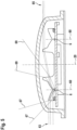
- Figure 3 shows a schematic vertical cross-sectional view of an exterior aircraft light according to an exemplary embodiment of the invention.
- the exterior aircraft light is a fuselage-mounted aircraft beacon light 2.
- the aircraft beacon light 2 may for example be employed as the upper aircraft beacon light 120a and/or as the lower aircraft beacon light 120, depicted in Figures 1 and 2 .
- the aircraft beacon light 2 of Figure 3 has a mounting portion 40, which is configured for mounting the aircraft beacon light 2 to the aircraft 100, in particular to the fuselage 160 of the aircraft 100, as it is depicted in Figures 1 and 2 .
- the aircraft beacon light 2 further comprises a disk-shaped support 4.
- the support 4 has a central portion.
- a plurality of light sources 6 are arranged on the support 4 around the central portion of the support 4.
- the plurality of light sources 6 may in particular be arranged in an annular configuration around the central portion of the support 4, with two of said plurality of light sources 6 being depicted in the cross-sectional view of Figure 3 .
- the light sources 6 may be LEDs.
- the support 4 is in turn supported by a support structure 42, which is arranged between the mounting portion 40 and the support 4.
- the mounting portion 40 may be formed integrally with the support structure 42.
- the support structure 42 provides mechanical support to the support 4. It may further provide a cooling structure and a cooling space for transferring heat, which is generated by the plurality of light sources 6 in operation, away from the plurality of light sources 6.
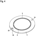
- Figure 4 shows a schematic perspective view of selected components of the aircraft beacon light 2 of Figure 3 .
- Figure 4 depicts the disc-shaped support 4 and the annular configuration of light sources 6 in a perspective view.
- Various components of the aircraft beacon light 2 of Figures 3 and 4 have rotational symmetry with respect to a central axis of symmetry 20.
- the support 4 and the annular configuration of light sources 6 have rotational symmetry.
- the lens structure 8 is a rotationally symmetric component and has various annular optical surfaces, which will be described in detail below.
- the cross-sectional view of Figure 3 shows two mirror-symmetrical portions of the lens structure 8 towards the left and towards the right of the central portion of the support 4. It is understood that the individual surfaces and portions of the lens structure 8, which will be described below, extend around the central portion of the support 4 in a revolving manner. It is further understood that the lens structure 8 may or may not be continuous through the central portion of the support 4 and may thus cover a large portion of the support 4.
- the second light sensor 24 is arranged to receive light emitted by one or more of the plurality of light sources 6 and reflected by the rearward facing portion 14 of the light transmissive cover 10.
- the second shutter 34 is shaped and arranged to enclose the second light sensor 24, with the exception of a second light entry port 38.
- the second shutter 34 contributes to the orientation of the second light sensor 24 towards the rearward facing portion 14 of the light transmissive cover 10. In other words, the second shutter 34 helps that the second light sensor 24 predominantly senses light that arrives from the rearward facing portion 14 of the light transmissive cover 10.
- Basing the determination regarding the extent of erosion of the light transmissive cover 10 on ratio values or difference values of the sensor measurements of the first and second light sensors 22, 24 may additionally allow for eliminating or reducing the measurement uncertainty that may be created by different levels of ambient light and/or by stray light within the aircraft beacon light 2 and/or by light components of other origin and/or by light output variations due to aging of the light sources 4 and/or temporary light output reductions due to thermal stresses on the light sources 4. It may become possible to use measurement values, obtained under vastly different environmental conditions and/or at very different points in time, in a meaningful manner. The data basis for monitoring erosion of the light transmissive cover may be greatly increased.
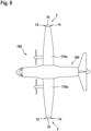
- the principles of obtaining sensor measurements with a first light sensor, oriented towards the forward facing portion 12, and a second light sensor, oriented towards the rearward facing portion 14, and of determining an extent of erosion of the light transmissive cover 10 on the basis of the sensor measurements of the first and second light sensors, as described above, are applicable to the exterior aircraft lights 2 of the aircraft 100 of Figure 8 in an analogous manner. It is understood that the number, arrangement, and colors of light sources may be different in such an embodiment, as compared to the exterior aircraft light 2 of Figures 3 to 7 .
Landscapes
- Engineering & Computer Science (AREA)
- Aviation & Aerospace Engineering (AREA)
- General Engineering & Computer Science (AREA)
- Biochemistry (AREA)
- Health & Medical Sciences (AREA)
- Life Sciences & Earth Sciences (AREA)
- Chemical & Material Sciences (AREA)
- Analytical Chemistry (AREA)
- Physics & Mathematics (AREA)
- General Health & Medical Sciences (AREA)
- General Physics & Mathematics (AREA)
- Immunology (AREA)
- Pathology (AREA)
- Photometry And Measurement Of Optical Pulse Characteristics (AREA)
- Geophysics And Detection Of Objects (AREA)
- Traffic Control Systems (AREA)
Abstract
Description
- The present invention relates to an exterior aircraft light, to an aircraft comprising such an exterior aircraft light, and to a method of monitoring erosion of a light transmissive cover of an exterior aircraft light.
- Almost all aircraft are equipped with exterior aircraft lights. In particular, large passenger air planes are provided with a wide variety of exterior aircraft lights. The exterior aircraft lights are provided for a wide variety of different purposes, such as for allowing the passengers and/or air crew to view the outside, for passive visibility, for signalling purposes, etc. Examples of such exterior aircraft lights are navigation lights, also referred to as position lights, red-flashing beacon lights, white strobe anti-collision lights, wing scan lights, take-off lights, landing lights, taxi lights, runway turn-off lights, etc.
- Exterior aircraft lights are exposed to very hazardous conditions. They have to withstand large aerodynamic forces, excessive particle impacts at high travelling velocities, as well as large temperature variations. The hazardous conditions, in particular the particle impacts at high travelling velocities, cause erosion of light transmissive covers of exterior aircraft lights. Erosion of the light transmissive cover may eventually degrade the light output of the exterior aircraft light in an unacceptable manner, leading to the exterior aircraft light no longer being considered airworthy. Up until now, erosion of light transmissive covers has been assessed mainly by highly subjective observations with naked eyes.
- Accordingly, it would be beneficial to provide an exterior aircraft light with highly reliable integrated monitoring of the erosion of the light transmissive cover. Further, it would be beneficial to provide an aircraft with such an exterior aircraft light and to provide an according method of monitoring erosion of a light transmissive cover of an exterior aircraft light.
- Exemplary embodiments of the invention include an exterior aircraft light with cover erosion monitoring, the exterior aircraft light comprising: a support; at least one light source, arranged on the support; a light transmissive cover, arranged over the at least one light source, the light transmissive cover having a forward facing portion and a rearward facing portion; a first light sensor, arranged to receive light emitted by the at least one light source and reflected towards the first light sensor by the forward facing portion of the light transmissive cover; and a second light sensor, arranged to receive light emitted by the at least one light source and reflected towards the second light sensor by the rearward facing portion of the light transmissive cover; wherein the exterior aircraft light is configured to provide an indication regarding an extent of erosion of the light transmissive cover on the basis of sensor measurements of the first light sensor and sensor measurements of the second light sensor.
- Exemplary embodiments of the invention allow for a highly reliable monitoring of the erosion of the light transmissive cover of an exterior aircraft light. As compared to previous approaches, the cover erosion monitoring does not rely on a human estimate of the erosion of the light transmissive cover. Rather, an automated monitoring of the light transmissive cover of the exterior aircraft light may become possible, with said automated monitoring having comparably low complexity, high ease of use, and high reliability. By monitoring the light, reflected by a forward facing portion of the light transmissive cover, and the light, reflected by a rearward facing portion of the light transmissive cover, a highly reliable monitoring of the erosion of the light transmissive cover may be achieved. Due to erosion predominantly or exclusively taking place at the forward facing portion of the light transmissive cover and due to the reflective action of the forward facing portion of the light transmissive cover increasing for light, coming from within the exterior aircraft light, the spread between the sensor measurements of the first light sensor and the sensor measurements of the second light sensor increases with erosion of the light transmissive cover.
- Providing the indication regarding the extent of erosion of the basis of both the sensor measurements of the first light sensor and the sensor measurements of the second light sensor allows for a highly reliable determination of the extent of erosion. By comparing the sensor measurements of the first light sensor and the sensor measurements of the second light sensor, i.e. by comparing first sensor measurements that depend on erosion and second sensor measurements that are substantially independent of erosion of the light transmissive cover, the monitoring of the erosion of the light transmissive cover may be made substantially or even completely independent of other factors that may otherwise prevent accurate measurements. For example, an ambient light component of the sensor measurements may be present in both the sensor measurements of the first light sensor and of the second light sensor, and its disturbance of sensor measurements may be reduced or eliminated. As another example, a degradation of the at least one light source, such as an aging of LED light source(s), and/or a temporary reduction in light output due to a high operating temperature of the at least one light source may be present in both the sensor measurements of the first light sensor and of the second light sensor, and their disturbance of sensor measurements may be reduced or eliminated. A differential approach on the basis of sensor measurements of the first light sensor and sensor measurements of the second light sensor may provide for highly reliable results, while having a manageable complexity.
- The exterior aircraft light is an exterior aircraft light with cover erosion monitoring, i.e. an exterior aircraft light with an integrated monitoring of the erosion of the light transmissive cover. It may also be said that an exterior aircraft light with cover erosion monitoring is an exterior aircraft light that has components for the monitoring of the erosion of the protective cover integrated into the exterior aircraft light. The exterior aircraft light has sensor and evaluation capacities to monitor the erosion of the light transmissive cover.
- The exterior aircraft light is configured to provide an indication regarding an extent of erosion of the light transmissive cover on the basis of sensor measurements of the first light sensor and sensor measurements of the second light sensor. In particular, the exterior aircraft light may have a controller that is coupled to the first light sensor and to the second light sensor. Said controller may receive the sensor measurements of the first light sensor and the sensor measurements of the second light sensor and may have an evaluation logic to provide the indication regarding the extent of erosion of the light transmissive cover. The controller may further have a memory to store the sensor measurements of the first and second light sensors over time. The controller may be embodied in hardware or in a suitable combination of hardware and software.
- The exterior aircraft light is configured to provide an indication regarding an extent of erosion of the light transmissive cover. The indication may be provided in the form of a signal that may be communicated to an entity outside of the exterior light, such as to a board computer of the aircraft. The signal may be communicated in a wired or wireless manner. It is also possible that the indication regarding the extent of erosion of the light transmissive cover is stored in the exterior aircraft light, such as in the memory of a controller of the exterior aircraft light, and may be read out via a suitable portable diagnostic device. It is further possible that the indication is given in a visual manner, such as via a status indication light source that is visible from outside the exterior aircraft light and that may for example be checked in the pre-flight routine. The indication regarding the extent of erosion of the light transmissive cover may be a quantitative indication regarding the extent of erosion. However, it is also possible that the indication is a binary indication, solely indicating whether the light transmissive cover is still considered airworthy or not.
- The exterior aircraft light is configured to provide an indication regarding an extent of erosion of the light transmissive cover on the basis of sensor measurements of the first light sensor and sensor measurements of the second light sensor. In particular, the exterior aircraft light may be configured to relate the sensor measurements of the first light sensor to the sensor measurements of the second light sensor. Further in particular, said relating of the sensor measurements of the first light sensor and the sensor measurements of the second light sensor may take place over time. In that case, respective sensor measurements of the first and second light sensors, taken substanially at the same time, may be related. In this way, a time line regarding a relative behavior of the sensor measurements of the first light sensor and the sensor measurements of the second light sensor may be provided and may be used for evaluating the extent of erosion. With said comparative/relative approach of looking at the sensor measurements of the first light sensor and the sensor measurements of the second light sensor and with monitoring the development of the comparative / relative information over time, a highly reliable monitoring of the erosion of the light transmissive cover may be achieved. Details regarding different approaches for comparing / relating the sensor measurements of the first and second light sensors will be given below.
- The exterior aircraft light has a light transmissive cover, arranged over the at least one light source. The light transmissive cover may be arranged over the at least one light source only or may be arranged over the support and the at least one light source. The light transmissive cover is a protective cover for the interior of the exterior aircraft light. In particular, the light transmissive cover may protect the interior of the exterior aircraft light from hazardous exhaust gases, from rain / snow, from excessive moisture, from particle impact caused by the impinging air stream during flight, and/or from impact of larger objects, such as birds. The light transmissive cover may be releasably mounted to the remainder of the exterior aircraft light, such that the light transmissive cover may be replaced when reaching an unacceptable extent of erosion or another type of major damage.
- The exterior aircraft light has a first light sensor, arranged to receive light emitted by the at least one light source and reflected towards the first light sensor by the forward facing portion of the light transmissive cover. The forward facing portion of the light transmissive cover may be defined as that part of the light transmissive cover where the tangent to the outer surface of the light transmissive cover has an angle of more than 35° with respect to the impinging air stream during flight, i.e. an angle of more than 35° with respect to the forward flight direction. It has been found that most erosion takes place in this part of the light transmissive cover, i.e. in the part of the light transmissive cover where the impinging air stream hits the light transmissive cover in an orthogonal or substantially head-on manner.
- The exterior aircraft light has a second light sensor, arranged to receive light emitted by the at least one light source and reflected towards the second light sensor by the rearward facing portion of the light transmissive cover. The rearward facing portion may be defined as that part of the light transmissive cover that is not exposed to an impinging air stream during flight. In particular, the rearward facing portion may be defined as that part of the light transmissive cover where the air stream is parallel to the tangent to the outer surface of the light transmissive cover, i.e. where the air stream passes along the outer surface of the light transmissive cover, or where the air stream detaches from the outer surface of the light transmissive cover, i.e. where the air stream diverges from the tangent to the outer surface of the light transmissive cover. For the example of fuselage-mounted light transmissive covers, the rearward facing portion may be the rear half of the light transmissive cover.
- The light transmissive cover has a forward facing portion and a rearward facing portion. The forward and rearward facing portions may in particular be opposite portions of the light transmissive cover.
- The exterior aircraft light has at least one light source, arranged on the support. The exterior aircraft light may have exactly one light source or may have a plurality of light sources. In the latter case, the light that is eventually received by the first light sensor and by the second light sensor does not have to come from all of the plurality of light sources nor from the same one or same ones of the plurality of light sources. In particular, it is possible that the light that is eventually received by the first light sensor originates from generally forward directed light source(s) and that the light that is eventually received by the second light sensor originates from generally rearward directed light source(s). The terminology that the exterior aircraft light has at least one light source, that the light sensor is arranged to receive light emitted by the at least one light source and reflected towards the first light sensor by the forward facing portion of the light transmissive cover, and that the second light sensor is arranged to receive light emitted by the at least one light source and reflected towards the second light sensor by the rearward facing portion of the light transmissive cover is not meant to imply a restriction regarding which particular light source emits the light that is eventually received by the respective light sensors.
- The at least one light source may be at least one LED. In particular, each of the at least one light source may be an LED.
- The first / second light sensor is arranged to receive light emitted by the at least one light source and reflected towards the first / second light sensor by the forward / rearward facing portion of the light transmissive cover. The first light sensor may be said to be oriented towards the forward facing portion of the light transmissive cover, and the second light sensor may be said to be oriented towards the rearward facing portion of the light transmissive cover. This terminology is not meant to imply that the first / second light sensor only receives light emitted by the at least one light source and reflected directly towards the first / second light sensor. Rather, the first and second light sensors may also pick up other light, such as ambient light, stray light within the exterior aircraft light, etc. However, with the provision of the first and second light sensors and their orientation towards the forward and rearward facing portions of the light transmissive cover, it may be possible to monitor the erosion of the light transmissive cover largely independent from such disturbing light components.
- According to a further embodiment, the exterior aircraft light is configured to provide the indication regarding the extent of erosion of the light transmissive cover on the basis of ratio values of the sensor measurements of the first light sensor and the sensor measurements of the second light sensor. Determining the indication regarding the extent of erosion on the basis of ratio values may provide for a particularly effective way of eliminating disturbing factors that affect the sensor measurements of the first and second light sensors in the same or similar manner. For example, ratio values may be particularly effective in reducing or eliminating the influence of ambient light and/or stray light within the exterior aircraft light and/or light source degradation and/or light output reduction due to high operating temperatures of the light source(s) and/or other factors that may be detrimental to the measurement accuracy between the first and second sensors and/ or detrimental to the comparability of measurement values over time.
- According to a further embodiment, the exterior aircraft light is configured to provide a worn cover indication when the ratio values of the sensor measurements of the first light sensor and the sensor measurements of the second light sensor are above a worn cover threshold value. The worn cover indication may indicate that the light transmissive cover of the exterior aircraft light is to be replaced at the next possible time, such as at the next scheduled maintenance or at an extra-curricular maintenance. The worn cover threshold value may correspond to an extent of erosion at which the exterior aircraft light is no longer considered airworthy. It is also possible that the worn cover threshold value indicates an extent of erosion at which the exterior aircraft light is still considered airworthy, but not far away from no longer being considered airworthy. In this way, the worn cover indication may provide for a timely planning of a replacement of the light transmissive cover.
- According to a further embodiment, the exterior aircraft light is configured to provide the worn cover indication when the ratio values of the sensor measurements of the first light sensor and the sensor measurements of the second light sensor are on average above the worn cover threshold value within a predetermined erosion monitoring time interval. In this way, outside conditions that temporarily make the provision of meaningful sensor measurements impossible may be prevented from triggering a worn cover event. Examples of such conditions may be snow or excessive icing on the light transmissive cover, bird feces on the light transmissive cover, excessive dirt from exhaust gases on the light transmissive cover, etc.
- According to a further embodiment, the exterior aircraft light is configured to provide the worn cover indication when at least a predefined percentage of the ratio values of the sensor measurements of the first light sensor and the sensor measurements of the second light sensor are above the worn cover threshold value within a predetermined erosion monitoring time interval. Said predefined percentage may be 70% or 80% or 90% or 95% or another suitable percentage value. This binning of ratio values with respect to the worn cover threshold value may be employed as an alternative or additional means for preventing a wrong triggering of the worn cover event, as compared to the monitoring of the average described above.
- The erosion monitoring time interval may cover a predetermined time interval from a momentary point in time into the past. In other words, the erosion monitoring time interval may be a moving window with respect to the sensor measurements taken over time, i.e. a moving window with respect to the time series of sensor measurements generated by the first and second light sensors.
- According to a further embodiment, the predetermined erosion monitoring time interval is between 1 week and 3 months. In particular, the predetermined erosion monitoring time interval may be between 2 weeks and 2 months. The given time intervals have been found to provide a good trade-off between obtaining a highly reliable determination regarding the extent of erosion of the light transmissive cover, while reacting to the process of erosion of the light transmissive cover in an adequate time frame.
- According to a further embodiment, the worn cover threshold value is between 1.5 and 4. This worn cover threshold value is applied under the assumption that the ratio value of the sensor measurements of the first light sensor and the sensor measurements of the second light sensor is normalized at 1, when the exterior aircraft light is put into service, i.e. when the light transmissive cover is in a non-eroded state. The given value range has been found to provide a particularly reliable determination of a worn light transmissive cover, i.e. of a light transmissive cover that is to be serviced / maintained / replaced, while maintaining a long service life of the light transmissive cover.
- According to a further embodiment, the exterior aircraft light is configured to provide the indication regarding the extent of erosion of the light transmissive cover on the basis of difference values of the sensor measurements of the first light sensor and the sensor measurements of the second light sensor. Evaluating difference values of the sensor measurements of the first light sensor and sensor measurements of the second light sensor may also provide for a highly effective way of monitoring the state of erosion of the light transmissive cover of the exterior aircraft light. In particular, evaluating difference values may also allow for reducing or eliminating an undesired disturbance of the sensor measurements by ambient light, stray light within the exterior aircraft light, light source degradation, temporary light output reduction due to high operating temperatures of the light source(s), etc. The additional features, modifications, and effects, as described above with respect to the usage of ratio values, may be applied to the indication regarding the extent of erosion of the light transmissive cover on the basis of difference values in an analagous manner.
- According to a further embodiment, the exterior aircraft light further comprises: a first shutter, arranged over the first light sensor, wherein the first shutter has a first light entry port oriented towards the forward facing portion of the light transmissive cover; and/or a second shutter, arranged over the second light sensor, wherein the second shutter has a second light entry port oriented towards the rearward facing portion of the light transmissive cover. In this way, the influence of disturbing light components, such as ambient light, stray light within the exterior aircraft light, etc., on the sensor measurements of the first and second light sensors may be kept particularly low. A particularly high reliability in determining the extent of erosion of the light transmissive cover may be achieved.
- According to a further embodiment, the first shutter encloses the first light sensor, with the exception of the first light entry port, and/or the second shutter encloses a second light sensor, with the exception of the second light entry port.
- According to a further embodiment, the first light sensor and/or the second light sensor are arranged on the support. In this way, the at least one light source, the first sensor, and the second light sensor may be jointly supported by the support. The support may be a circuit board, in particular a printed circuit board (PCB). In this way, the support may provide the mechanical support for the at least one light source and the first and/or second light sensors and may provide the electric connections for the at least one light source and the first and/or second light sensors. The controller of the exterior aircraft light may also be arranged on the support. Other electric components of the exterior aircraft light, such as a status indication light source, may also be arranged on the support.
- According to a further embodiment, the exterior aircraft light is configured to provide an indication regarding an extent of degradation of the at least one light source on the basis of sensor measurements of the second light sensor. In particular, the exterior aircraft light may be configured to provide an indication regarding aging / long term degradation of the at least one light source on the basis of sensor measurements of the second light sensor. The aging / long term degradation of the at least one light source may be due to thermal and/or electric stresses over time. As the sensor measurements of the second light sensor are largely or fully independent of the erosion of the light transmissive cover, the sensor measurements of the second light sensor may allow for a highly reliable determination of the degradation of the at least one light source. In order to make said determination largely or fully independent of other variables, such as different levels of ambient light, it is possible to obtain the sensor measurements for the indication regarding an extent of degradation under laboratory conditions, e.g. by placing a cover / hood over the exterior aircraft light. It is also possible to compare the lowest sensor measurements within respective degradation monitoring time intervals over time. It may be assumed that, within each degradation monitoring time interval, there is at least one instance of an operation of the exterior aircraft light under well-defined environmental conditions, such as a night flight. The degradation monitoring time interval may be between 1 week and 3 months, in particular between 2 weeks and 2 months. With the described set-up, it may be possible to carry out an erosion monitoring of the light transmissive cover and a degradation monitoring of the at least one light source with two sensors only. As compared to previous approaches, which used three sensors for providing the two functionalities, the sensor capacities may be reduced by 33%.
- According to a further embodiment, the exterior aircraft light is a fuselage-mounted aircraft beacon light. The aircraft beacon light may be a red-flashing aircraft beacon light, such as an aircraft beacon light with red light sources that emit sequences of red light flashes in operation. The terminology of the exterior aircraft light being a fuselage-mounted aircraft beacon light means that the exterior aircraft light is configured / adapted to be mounted to the fuselage of an aircraft.
- The fuselage-mounted aircraft beacon light may have a bowl-shaped / cup-shaped light transmissive cover. The light transmissive cover may have another suitable shape, such as teardrop shape, as well. With these kinds of shapes of the light transmissive cover, the forward facing portion and the rearward facing portion of the light transmissive cover may be conveniently positioned on opposite sides of the light transmissive cover in the longitudinal direction of the fuselage of the aircraft. Accordingly, such fuselage-mounted aircraft beacon lights may provide for ample room for providing and suitably orienting the first and second light sensors.
- According to a further embodiment, the exterior aircraft light comprises a plurality of light sources, arranged on the support. In particular, the plurality of light sources may be arranged in an annular configuration on the support, and the first light sensor and the second light sensor may be arranged laterally outwards of the annular configuration of the plurality of light sources. The annular arrangement of the plurality of light sources may be particularly suitable for fuselage-mounted aircraft beacon lights. The plurality of light sources, the first light sensor, and the second light sensor may in particular be arranged in a rotationally symmetric arrangement.
- According to a further embodiment, the exterior aircraft light comprises an optical system for shaping the desired exterior aircraft light output, such as the desired beacon light output, from the light emitted by the at least one light source / by the plurality of light sources. The optical system may comprise one or more lenses and/or one or more reflectors and/or one or more shutters. In a particular embodiment, the optical system may comprise a unitary lens structure that is arranged over the plurality of light sources and, optionally, over the first and second light sensors and that is rotationally symmetric with respect to the center axis of the annular configuration of the plurality of light sources.
- According to a further embodiment, the exterior aircraft light is a wing-end-mounted exterior aircraft light. When mounted to the end of a wing, an exterior aircraft light may take over part of the forward lighting functionalities and part of the rearward lighting functionalities of an exterior aircraft lighting system. The light transmissive cover of such an exterior aircraft light may be a three-dimensional structure, in particular a three-dimensional structure having a substantially semi-circular or semi-elliptical horizontal cross-section. In this way, the light transmissive cover may have a forward facing portion and a rearward facing portion that are highly suitable for implementing the erosion monitoring described herein.
- According to a further embodiment, the wing-end-mounted exterior aircraft light is a wing-end-mounted aircraft navigation light or a wing-end-mounted red-flashing beacon light or a wing-end-mounted white strobe anti-collision light or a wing-end-mounted multi-function light providing the functionalities of two or all of an aircraft navigation light, a red-flashing beacon light, and a white strobe anti-collision light.
- Exemplary embodiments of the invention further include an aircraft, comprising at least one exterior aircraft light in accordance with any of the embodiments described above. The aircraft may be an air plane or a rotocraft. The additional features, modifications, and effects, as described above with respect to the exterior aircraft light, apply to the aircraft in an analogous manner.
- According to a further embodiment, the aircraft comprises an upper fuselage-mounted aircraft beacon light, as described in any of the embodiments above, mounted to an upper portion of a fuselage of the aircraft, and/or a lower fuselage-mounted aircraft beacon light, as described in any of the embodiments above, mounted to a lower portion of the fuselage of the aircraft.
- Exemplary embodiments of the invention further include a method of monitoring erosion of a light transmissive cover of an exterior aircraft light having at least one light source, the method comprising: obtaining first sensor measurements with a first light sensor, the first light sensor arranged to receive light emitted by the at least one light source and reflected by a forward facing portion of the light transmissive cover; obtaining second sensor measurements with a second light sensor, the second light sensor arranged to receive light emitted by the at least one light source and reflected by a rearward facing portion of the light transmissive cover; relating the first sensor measurements and the second sensor measurements; and providing an indication regarding an extent of erosion of the light transmissive cover on the basis of said relating of the first sensor measurements and the second sensor measurements. The additional features, modifications and effects, as described above with respect to the exterior aircraft light, apply to the method of monitoring erosion of a light transmissive cover in an analagous manner.
- According to a further embodiment, said relating of the first sensor measurements and the second sensor measurements comprises determining ratio values of the first sensor measurements and the second sensor measurements.
- According to a further embodiment, the method comprises providing a worn cover indication when the ratio values are above a worn cover threshold value.
- Further exemplary embodiments of the invention are described below with respect to the accompanying drawings, wherein:
-
Figure 1 shows a schematic top view of an aircraft according to an exemplary embodiment of the invention, which is equipped with two aircraft beacon lights according to exemplary embodiments of the invention. -
Figure 2 shows a schematic front view of the aircraft shown inFigure 1 . -
Figure 3 shows a schematic vertical cross-sectional view of an exterior aircraft light in accordance with an exemplary embodiment of the invention. -
Figure 4 shows a schematic perspective view of selected components of the exterior aircraft light ofFigure 3 . -
Figure 5 shows the exterior aircraft light ofFigure 3 in the same cross-sectional view, with exemplary light rays illustrating the light output of the exterior aircraft light. -
Figure 6 shows an enlarged version of a rear portion of the exterior aircraft light ofFigure 3 in the same cross-sectional view, with exemplary light rays illustrating part of the light sensing for monitoring erosion of the light transmissive cover. -
Figure 7 shows an enlarged version of a front portion of the exterior aircraft light ofFigure 3 in the same cross-sectional view, with exemplary light rays illustrating part of the light sensing for monitoring erosion of the light transmissive cover. -
Figure 8 shows a schematic top view of an aircraft according to another exemplary embodiment of the invention, which is equipped with two wing-end-mounted exterior aircraft lights according to exemplary embodiments of the invention. -
Figure 1 shows a schematic top view of anaircraft 100 according to an exemplary embodiment of the invention. In the exemplary embodiment ofFigure 1 , the aircraft is a commercialpassenger air plane 100.Figure 2 shows a schematic front view of theaircraft 100. - The
aircraft 100 comprises afuselage 160 and twowings fuselage 160. Arespective engine wings aircraft 100 further comprises twohorizontal stabilizers vertical stabilizer 150, which are mounted to an aft portion of thefuselage 160. - The
aircraft 100 is equipped with a variety of exterior aircraft lights. - Out of all the exterior aircraft lights, which may be provided at the exterior of the
aircraft 100, only three white strobeanti-collision lights beacon lights Figures 1 and2 . Theaircraft 100 may be equipped with additional exterior lights, which may in particular include at least one or any subset or all of navigation lights, logo lights, wing scan lights, engine scan lights, cargo loading lights, take-off lights, taxi lights, landing lights, and/or runway turn-off lights. For clarity and simplicity of illustration and description, these additional types of exterior lights are not depicted inFigures 1 and2 . It is, however, pointed out that the white strobeanti-collision lights exterior aircraft light 128a would provide a white strobe anti-collision light output and a green navigation light output, the exterior aircraft light 128b would provide a white strobe anti-collision light output and a red navigation light output, and the exterior aircraft light 128c would provide a white strobe anti-collision light output and a white navigation light output. - The
aircraft 100 shown inFigures 1 and2 is equipped with an upper red-flashingbeacon light 120a, which is installed in an upper portion of theaircraft 100, in particular on top of thefuselage 160. In an alternative configuration, the upper red-flashingbeacon light 120a may be installed in an upper portion of thevertical stabilizer 150, in particular on top of thevertical stabilizer 150. - The
aircraft 100 further comprises a lower red-flashing beacon light 120b, which is installed in a lower portion of theaircraft 100. The lower red-flashing beacon light 120b may in particular be mounted to the bottom of thefuselage 160. - Although only one lower red-flashing beacon light 120b is depicted in
Figures 1 and2 , theaircraft 100 may comprise two or more lower red-flashing beacon lights, which may be installed at different positions along the longitudinal extension of thefuselage 160. A first lower red-flashing beacon light may, for example, be mounted to a front portion of thefuselage 160 close to the front gear of theaircraft 100, and a second lower red-flashing beacon light may, for example, be mounted to a middle portion of thefuselage 160 close to the main gear of theaircraft 100 and/or to an aft portion of the fuselage below the horizontal andvertical stabilizers - In alternative configurations, red-flashing beacon lights may be installed at the tips of the
wings tail 110 of theaircraft 100, potentially supplemented by red-flashing beacon lights on the side walls of thefuselage 160 and/or on the bottom of thefuselage 160. - In the exemplary embodiments of
Figures 1 and2 , the upper red-flashingbeacon light 120a and the lower red-flashingbeacon light 120b are exterior aircraft lights in accordance with exemplary embodiments of the invention. An exemplary embodiment of such fuselage-mounted aircraft beacon lights is described below with respect toFigures 3 to 7 . - Commonly, the red-flashing
beacon lights engines aircraft 100 that theengines - As mentioned, the
aircraft 100 is equipped with three white strobeanti-collision lights anti-collision lights wings wings anti-collision light 128c is installed at thetail 110 of theaircraft 100. - The white strobe
anti-collision lights aircraft 100. It is also possible that the white strobeanti-collision lights -
Figure 3 shows a schematic vertical cross-sectional view of an exterior aircraft light according to an exemplary embodiment of the invention. In the exemplary embodiment ofFigure 3 , the exterior aircraft light is a fuselage-mountedaircraft beacon light 2. Theaircraft beacon light 2 may for example be employed as the upper aircraft beacon light 120a and/or as the lower aircraft beacon light 120, depicted inFigures 1 and2 . - The
aircraft beacon light 2 ofFigure 3 has a mountingportion 40, which is configured for mounting theaircraft beacon light 2 to theaircraft 100, in particular to thefuselage 160 of theaircraft 100, as it is depicted inFigures 1 and2 . - The
aircraft beacon light 2 further comprises a disk-shapedsupport 4. Thesupport 4 has a central portion. A plurality oflight sources 6 are arranged on thesupport 4 around the central portion of thesupport 4. The plurality oflight sources 6 may in particular be arranged in an annular configuration around the central portion of thesupport 4, with two of said plurality oflight sources 6 being depicted in the cross-sectional view ofFigure 3 . Thelight sources 6 may be LEDs. - The
support 4 is in turn supported by asupport structure 42, which is arranged between the mountingportion 40 and thesupport 4. The mountingportion 40 may be formed integrally with thesupport structure 42. Thesupport structure 42 provides mechanical support to thesupport 4. It may further provide a cooling structure and a cooling space for transferring heat, which is generated by the plurality oflight sources 6 in operation, away from the plurality oflight sources 6. -
Figure 4 shows a schematic perspective view of selected components of theaircraft beacon light 2 ofFigure 3 .Figure 4 depicts the disc-shapedsupport 4 and the annular configuration oflight sources 6 in a perspective view. Various components of theaircraft beacon light 2 ofFigures 3 and4 have rotational symmetry with respect to a central axis ofsymmetry 20. In particular, thesupport 4 and the annular configuration oflight sources 6 have rotational symmetry. - The vertical cross-sectional view of
Figure 3 is a longitudinal cross-sectional view through theaircraft beacon light 2. The cross-sectional view ofFigure 3 may in particular be taken along the longitudinal axis of the fuselage of the aircraft, when theaircraft beacon light 2 is mounted to the fuselage. In other words, the cross-sectional view ofFigure 3 is a longitudinal cross-sectional view in the aircraft frame of reference. The forward flight direction of the aircraft is indicated viaarrow 70 inFigure 3 . - In the exemplary embodiment of
Figures 3 and4 , the plurality oflight sources 6 are arranged in a circular manner around the axis ofsymmetry 20. The plurality oflight sources 6 are in particular arranged between the central portion of thesupport 4 and a circumferential periphery of thesupport 4. It is pointed out that other arrangements of light sources are possible as well. It is also possible that only one light source is present. Said one light source may for example be provided in the central portion of thesupport 4. - In the exemplary embodiment of
Figures 3 and4 , the plurality oflight sources 6 are red LEDs. Optionally, the plurality oflight sources 6 may comprise a combination of red LEDs and white LEDs and/or infrared LEDs. It is also possible that the plurality oflight sources 6 are white LEDs and a red color filter is provided in theaircraft beacon light 2. - The
aircraft beacon light 2 further comprises alens structure 8. Thelens structure 8 is arranged and configured for forming a beacon light output from the light emitted by the plurality oflight sources 6. Thelens structure 8 is shown inFigure 3 , but not inFigure 4 . - In the exemplary embodiment of
Figure 3 , thelens structure 8 is a unitary, rotationally symmetric component, which is arranged within theaircraft beacon light 2 for conditioning the light output of theaircraft beacon light 2. Thelens structure 8 is arranged over the plurality oflight sources 6. Thelens structure 8 may be made from silicone or from PMMA or from another suitable material, and it may be molded over the plurality oflight sources 6 onto thesupport 4. In other words, during manufacture, the material of thelens structure 8 may be brought into its eventual shape in a molding process right over the plurality oflight sources 6 and thesupport 4. It is also possible that thelens structure 8 is molded as a separate element, which is later attached to thesupport 4, enclosing the plurality oflight sources 6 between thesupport 4 and thelens structure 8. - The
lens structure 8 is a rotationally symmetric component and has various annular optical surfaces, which will be described in detail below. The cross-sectional view ofFigure 3 shows two mirror-symmetrical portions of thelens structure 8 towards the left and towards the right of the central portion of thesupport 4. It is understood that the individual surfaces and portions of thelens structure 8, which will be described below, extend around the central portion of thesupport 4 in a revolving manner. It is further understood that thelens structure 8 may or may not be continuous through the central portion of thesupport 4 and may thus cover a large portion of thesupport 4. - The
lens structure 8 has a light entry surface, which is the boundary surface with respect to the plurality oflight sources 6, a first totalinternal reflection surface 82, which is distal from thesupport 4 and positioned laterally outwards of the plurality oflight sources 6, a second totalinternal reflection surface 86, which is distal from thesupport 4 and positioned laterally inwards of the plurality oflight sources 6, a firstlight exit surface 84, which is substantially orthogonal to thesupport 4 and forms the laterally outermost part of thelens structure 8, and a secondlight exit surface 88, which is close to orthogonal with respect to thesupport 4 and which is positioned between the plurality oflight sources 6 and the central portion of thesupport 4, i.e. laterally inwards of the plurality of thelight sources 6 and the second totalinternal reflection surface 86. - In addition, the
lens structure 8 of the exemplary embodiment ofFigure 3 comprises arefractive portion 90, which forms the most distal part of thelens structure 8 with respect to thesupport 4 and which is arranged between the secondlight exit surface 88 and the second totalinternal reflection surface 86, when considering the distance from the axis ofsymmetry 20. The optical effects of the various surfaces and portions of thelens structure 8 will be described below with respect toFigure 5 . - The
aircraft beacon light 2 further comprises alight transmissive cover 10, which is also shown inFigure 3 , but not inFigure 4 . Thelight transmissive cover 10 is mounted to the mountingportion 40 and forms an inner space between the mountingportion 40 and thelight transmissive cover 10. Thesupport 4, the plurality oflight sources 6, and thelens structure 8 are arranged in said inner space. Thelight transmissive cover 10 protects thelens structure 8, the plurality oflight sources 6, and thesupport 4 during flight of the aircraft and on the ground. - The
light transmissive cover 10 may be made from a transparent, color-less material, such as PMMA. Thelight transmissive cover 10 may also be made from another suitable material. In case white light sources are used for providing a red beacon light output, thelight transmissive cover 10 may comprise a red color filter or may be made from a red, light transmissive material. - In the exemplary embodiment of
Figure 3 , thelight transmissive cover 10 is bowl-shaped / cup-shaped and encloses thesupport 4, the plurality oflight sources 6, and thelens structure 8. Thelight transmissive cover 10 has a forward facingportion 12 and a rearward facingportion 14. In the cross-sectional view ofFigure 3 , the forward facingportion 12 and the rearward facingportion 14 are depicted as substantially straight line portions of thelight transmissive cover 10. It is understood that theforward facing portion 12 and the rearward facingportion 14 are extended portions of thelight transmissive cover 10 around the front end and around the rear end of thelight transmissive cover 10. - The
aircraft beacon light 2 further comprises afirst light sensor 22, afirst shutter 32, a secondlight sensor 24, and asecond shutter 34. Thefirst light sensor 22 and thefirst shutter 32 are arranged at a forward end portion of thesupport 4. The secondlight sensor 24 and thesecond shutter 34 are arranged at a rearward end portion of thesupport 4. Thefirst light sensor 22, thefirst shutter 32, the secondlight sensor 24, and thesecond shutter 34 are depicted in cross-section inFigure 3 and in a three-dimensional view inFigure 4 , wherever visible in the viewing direction ofFigure 4 . - The
first light sensor 22 is arranged to receive light emitted by one or more of the plurality oflight sources 6 and reflected by theforward facing portion 12 of thelight transmissive cover 10. Thefirst shutter 32 is shaped and arranged to enclose thefirst light sensor 22, with the exception of a firstlight entry port 36. Thefirst shutter 32 contributes to the orientation of thefirst light sensor 22 towards theforward facing portion 12 of thelight transmissive cover 10. In other words, thefirst shutter 32 helps that thefirst light sensor 22 predominantly senses light that arrives from the forward facingportion 12 of thelight transmissive cover 10. - The second
light sensor 24 is arranged to receive light emitted by one or more of the plurality oflight sources 6 and reflected by the rearward facingportion 14 of thelight transmissive cover 10. Thesecond shutter 34 is shaped and arranged to enclose the secondlight sensor 24, with the exception of a secondlight entry port 38. Thesecond shutter 34 contributes to the orientation of the secondlight sensor 24 towards the rearward facingportion 14 of thelight transmissive cover 10. In other words, thesecond shutter 34 helps that the secondlight sensor 24 predominantly senses light that arrives from the rearward facingportion 14 of thelight transmissive cover 10. - The
first shutter 32 and thesecond shutter 34 may have a low profile on top of thesupport 4. In this way, thefirst shutter 32 and thesecond shutter 34 may disturb / block the beacon light output of theaircraft beacon light 2 to a low degree or not at all. In a particular embodiment, thefirst shutter 32 and thesecond shutter 34 extend from thesupport 4 by at most 5 mm, in particular by at most 3 mm. The extension from thesupport 4 is understood as the extension in the dimension orthogonal to thesupport 4. - In the exemplary embodiment of
Figure 3 , thelens structure 8 is molded over thefirst light sensor 22, thefirst shutter 32, the secondlight sensor 24, and thesecond shutter 34. In other words, thefirst light sensor 22, thefirst shutter 32, the secondlight sensor 24, and thesecond shutter 34 are enclosed by thetransparent lens structure 8. It is also possible that thefirst light sensor 22, thefirst shutter 32, the secondlight sensor 24, and thesecond shutter 34 are arranged outside of thelens structure 8, for example laterally outwards of thelens structure 8. - With the
first light sensor 22 and the secondlight sensor 24, the erosion of thelight transmissive cover 10, in particular the erosion of theforward facing portion 12 of thelight transmissive cover 10, can be monitored. Exemplary details of such monitoring will be described below with respect toFigures 6 and 7 . - The
aircraft beacon light 2 further comprises acontroller 50. In the exemplary embodiment ofFigure 3 , thecontroller 50 is arranged on thesupport 4, in particular arranged on a back side of thesupport 4. Thecontroller 50 may also be provided in or at thesupport structure 42. Thecontroller 12 may also be provided in other locations in theaircraft beacon light 2. - The
controller 50 is coupled to the plurality oflight sources 6. Thecontroller 50 is configured for effecting a pulsed power supply to the plurality oflight sources 6 in operation. In this way, the plurality oflight sources 6 may provide for a red-flashing beacon light output of theaircraft beacon light 2. - The
controller 50 may be coupled to an on-board power supply network or to an according power adapter (not shown), and it may pass on the received electric power to the plurality oflight sources 6. Thecontroller 50 may be embodied entirely in hardware or it may comprise a suitable combination of hardware and software for achieving the desired control of the plurality oflight sources 6. - The
controller 50 is further coupled to thefirst light sensor 22 and to the secondlight sensor 24. Thecontroller 50 is configured to evaluate the sensor measurements of thefirst light sensor 22 and the secondlight sensor 24. In particular, thecontroller 50 is configured to determine an extent of erosion of thelight transmissive cover 10 by relating the sensor measurements of thefirst light sensor 22 and the sensor measurements of the secondlight sensor 24. Details of said determination will be described below with respect toFigures 6 and 7 . - Once the
controller 50 has determined that the light transmissive cover has degraded to an unacceptable extent, herein also referred to as a worn cover event, thecontroller 50 may control astatus indication LED 52 to provide a visual indication of the worn cover event. For example, thestatus indication LED 52 may be a yellow LED and thecontroller 50 may control thestatus indication LED 52 to light up when the aircraft is on the ground. With thestatus indication LED 52 being arranged at a rear end of thesupport 4 and being visible through thelight transmissive cover 10, the visual indication regarding the worn cover event may become apparent to ground personal and/or crew members that do a pre-flight check or a regular comprehensive aircraft check after a certain number of operating hours or a full aircraft check in the course of scheduled maintenance. As an alternative / in addition to providing the visual indication via thestatus indication LED 52, thecontroller 50 may transmit a worn cover signal to an outside entity, such as to the aircraft board computer and/or to a portable diagnostic device, via a suitable wired or wireless communication channel. -
Figure 5 shows theaircraft beacon light 2 ofFigure 3 in the same cross-sectional view.Figure 5 additionally shows exemplary light rays 63, 65, 67, 69, as emitted by thelight source 6 depicted on the left hand side ofFigure 4 . For enhancing the clarity of the illustration, no light rays emitted by thelight source 6 on the right hand side ofFigure 4 are shown. - In order to draw better attention to the exemplary light rays 63, 65, 67, 69, the reference numerals to the individual surfaces and portions of the
lens structure 8 are omitted fromFigure 5 . It is pointed out that the reference numerals ofFigure 3 apply toFigure 5 in complete analogy. - For ease of illustration, the principal
light emission directions 60 of thelight sources 6 are indicated as dashed lines inFigure 5 , with the principallight emission directions 60 being oriented orthogonal to thesupport 4. Thelight sources 6 are directed light sources, with the principallight emission direction 60 extending orthogonal to thesupport 4. - A first portion of the light, emitted by the
light sources 6, enters the lens structure right after exiting thelight sources 6, reaches the first totalinternal reflection surface 82, experiences total internal reflection at the first totalinternal reflection surface 82, and is reflected laterally outwards. The exemplary light rays 63, which illustrate said first portion of light, hit the firstlight exit surface 84 in an orthogonal manner and, therefore, pass the firstlight exit surface 84 without further refraction. - While being reflected laterally outwards, the first portion of light is collimated in a direction parallel to the
support 4, i.e. it is collimated within the horizontal plane in the aircraft frame of reference. For achieving said collimation, the first totalinternal reflection surface 82 has a parabolic shape in cross-section, as illustrated inFigures 3 and5 . The first portion of light encompasses the light as output by the plurality oflight sources 6 in an angular range of about 45° between the principallight emission directions 60 and 45° laterally outwards thereof. - A second portion of light enters the
lens structure 8 from the plurality oflight sources 6, reaches the second totalinternal reflection surface 86, experiences total internal reflection at the second totalinternal reflection surface 86, and exits thelens structure 8 for a first time at the secondlight exit surface 88. The second portion of light is illustrated via exemplary light rays 65. - The second total
internal reflection surface 86 is also parabolic. However, the parabolic shape is tilted in such a way with respect to thesupport 4 that the exemplary light rays 65 are not collimated parallel to thesupport 4, but somewhat angled upwards with respect to thesupport 4. The exemplary light rays 65 of the second portion of light experience an additional refraction at the secondlight exit surface 88. The second portion of light, after passing the secondlight exit surface 88, re-enters theoptical structure 8 at therefractive portion 90. Therefractive portion 90 refracts the second portion of light to be parallel or close to parallel with respect to thesupport 4. In this way, the second portion of light is also emitted in or close to the horizontal plane of theaircraft 100 in the aircraft frame of reference. The second portion of light encompasses the light as output by the plurality oflight sources 6 in an angular range of about 30° between the principallight emission directions 60 and 30° laterally inwards thereof. - A third portion of light emitted by the
light sources 6, which is illustrated by exemplary light rays 67, enters thelens structure 8 after being emitted by thelight sources 6 and propagates right to the firstlight exit surface 84. There, the third portion of light is refracted into various angular directions. The third portion of light encompasses the light as output by the plurality oflight sources 6 in an angular range of about 45° between 45° laterally outwards of the principallight emission directions 60 and parallel to thesupport 4. - A fourth portion of light, which is illustrated by exemplary light rays 69, enters the
lens structure 8 after being emitted by thelight sources 6 and propagates right to the secondlight exit surface 88 and therefractive portion 90. There, the fourth portion of light experiences refraction into various angular regions. The fourth portion of light encompasses the light as output by the plurality oflight sources 6 in an angular range of about 60° between 30° laterally inwards of the principallight emission directions 60 and parallel to thesupport 4. - With the given
lens structure 8, a highly efficient fulfilling of the FAR requirements foraircraft beacon lights 2, requiring a high intensity peak in the horizontal plane in the aircraft frame of reference and requiring a decreasing intensity for larger angles with respect to the horizontal plane, can be achieved. - The total internal reflection at the first and second total internal reflection surfaces 82, 86 may allow for providing the peak in the horizontal plane in a particularly space-efficient and energy-efficient manner. As compared to other approaches, where complex optical systems, based on metallic reflectors, were used, an FAR-compliant beacon light output may be achieved with up to 80% reduction in beacon light volume and up to 60% reduction in height over the fuselage 104. In this way, aerodynamic drag can be reduced, and the exposure to damaging particles and larger objects, such as birds, can be reduced.
- It is, however, explicitly pointed out that the formation of the beacon light output may also be achieved with other optical structure designs and that exemplary embodiments of the present invention may also employ such other optical structure designs.
-
Figure 6 shows an enlarged version of a rear portion of theaircraft beacon light 2 ofFigure 3 in the same cross-sectional view, with exemplary light rays illustrating part of the light sensing for monitoring erosion of thelight transmissive cover 10. In particular,Figure 6 shows that portion of theaircraft beacon light 2 that is depicted towards the right of the central axis ofsymmetry 20 inFigure 3 . - As described with respect to
Figure 5 , a first portion of light, as emitted by the plurality oflight sources 6, leaves theaircraft beacon light 2 substantially parallel with respect to thesupport 4. As inFigure 5 , said first portion of light is illustrated via exemplary light rays 63. When examining said first portion of light closely, not all of the light passes through the rearward facingportion 14 of thelight transmissive cover 10 in an unimpeded manner. A small fraction of the first portion of light experiences Fresnel reflection at the outer surface of thelight transmissive cover 10. This reflection may be due to surface imperfections at the inner and outer surfaces of thelight transmissive cover 10 and/or due to non-perfect collimation of the first portion of light and a reflection of angled light rays on thelight transmissive cover 10 and/or due to other factors. Part of said small fraction of the first portion of light reaches the secondlight sensor 24 and gives rise to sensor measurements at the secondlight sensor 24. This part of light is indicated withreference numeral 74 inFigure 6 . - The rearward facing
portion 14 of thelight transmissive cover 10 is not hit by an impinging air stream in operation. Therefore, the rearward facingportion 14 of thelight transmissive cover 10 does not experience erosion or only a minimal amount of erosion in use. When, hypothetically, assuming the light output of the plurality oflight sources 6 to be constant and when, hypothetically, assuming a constant amount of ambient light, the sensor measurements of the secondlight sensor 24 would stay substantially constant over time. In other words, the sensors measurements of the secondlight sensor 24 reflect the fact that only minimal or no erosion takes place at the rearward facingportion 14 of thelight transmissive cover 10. -
Figure 7 shows an enlarged version of a front portion of theaircraft beacon light 2 ofFigure 3 in the same cross-sectional view, with exemplary light rays illustrating part of the light sensing for monitoring erosion of thelight transmissive cover 10. In particular,Figure 7 shows that portion of theaircraft beacon light 2 that is depicted towards the left of the central axis ofsymmetry 20 inFigure 3 . - As described with respect to
Figure 5 , a first portion of light, as emitted by the plurality oflight sources 6, leaves theaircraft beacon light 2 substantially parallel with respect to thesupport 4. However, said highly collimated light output through theforward facing portion 12, substantially in parallel with thesupport 4, only takes place, as long as thelight transmissive cover 10 is in a non-eroded state. When the forward facingportion 12 of thelight transmissive cover 10 has experienced some erosion, as it is depicted inFigure 7 , the outer surface of theforward facing portion 12 of thelight transmissive cover 10 takes on a complex shape in terms of its optical properties. While some light still passes theforward facing portion 12 straight, some light experiences refraction at various angles, and some light experiences reflection at various angles. Part of the latter portion of light, i.e. part of the portion of light being reflected at the outer surface of theforward facing portion 12 of thelight transmissive cover 10, reaches thefirst light sensor 22 and gives rise to sensor measurements at thefirst light sensor 22. This part of light is indicated withreference numeral 72 inFigure 7 . - Over the course of time and with an ongoing erosion of the
forward facing portion 12 of thelight transmissive cover 10, the portion of light that is reflected at the outer surface of theforward facing portion 12 of thelight transmissive cover 10 increases. Similarly, the part of the light that reaches thefirst light sensor 22 after being reflected at the outer surface of theforward facing portion 12 of thelight transmissive cover 10 increases as well. - When considering both the substantially constant reflection of light towards the second
light sensor 24, as described above with respect toFigure 6 , and the increasing reflection of light towards thefirst light sensor 22 due to a progressing erosion of theforward facing portion 12 of thelight transmissive cover 10, as described above with respect toFigure 7 , it can be appreciated that the spread between the sensor measurements of thefirst light sensor 22 and the secondlight sensor 24 increases with an increase in erosion. The relation between the sensor measurements of thefirst light sensor 22 and the secondlight sensor 24 may be monitored over time, and a highly reliable determination with respect to the extent of erosion of thelight transmissive cover 10 may be obtained. - The increasing spread between the sensor measurements of the
first light sensor 22 and the sensor measurements of the secondlight sensor 24 may be monitored in terms of ratio values or difference values of the sensor measurements of the first and secondlight sensors light sensors light transmissive cover 10 has reached a critical level, such as a level where thelight transmissive cover 10 is to be replaced. - Basing the determination regarding the extent of erosion of the
light transmissive cover 10 on ratio values or difference values of the sensor measurements of the first and secondlight sensors aircraft beacon light 2 and/or by light components of other origin and/or by light output variations due to aging of thelight sources 4 and/or temporary light output reductions due to thermal stresses on thelight sources 4. It may become possible to use measurement values, obtained under vastly different environmental conditions and/or at very different points in time, in a meaningful manner. The data basis for monitoring erosion of the light transmissive cover may be greatly increased. - The
controller 50, as described above with respect toFigure 3 , may carry out above described evaluation of the sensor measurements of the first and secondlight sensors controller 50 may store the sensor measurements and/or the ratio / difference values and may determine the extent of erosion from the time series of sensor measurements and/or ratio values and/or difference values. Further in particular, thecontroller 50 may monitor whether the ratio / difference values are above a worn cover threshold value for a predetermined erosion monitoring time interval, at least on average, and/or whether a predefined percentage of the ratio / difference values are above the worn cover threshold value within a predetermined erosion monitoring time interval. In this way, thecontroller 50 may ensure that the slow process of erosion of thelight transmissive cover 10 is reliably monitored, while disregarding temporary disturbances of the sensor measurements, such as snow, excessive icing, dirt, light output reductions due to high operating temperatures of the light sources, or temporary sensor malfunctions. - The
controller 50 may also carry out a degradation monitoring. In particular, thecontroller 50 may evaluate the sensor measurements of the secondlight sensor 24 over time and may deduce the level of degradation of thelight sources 6 therefrom. With the sensor measurements of the secondlight sensor 24 being largely or fully independent of the erosion of thelight transmissive cover 10, a highly reliable determination of the degradation / aging of thelight sources 6 may be achieved. -
Figure 8 shows a schematic top view of anaircraft 100 according to an exemplary embodiment of the invention. In the exemplary embodiment ofFigure 8 , theaircraft 100 is a smaller size air plane, such as a private air plane for recreational or sports purposes. In particular, the air plane may be an air plane of less than 20 passengers. The aircraft has afuselage 160, aright wing 170a, and aleft wing 170b. Each of the right andleft wings - Further, the
aircraft 100 ofFigure 8 has twoexterior aircraft lights 2 in accordance with exemplary embodiments of the invention. Theexterior aircraft lights 2 are wing-end-mounted exterior aircraft lights and are provided on a left lateral end portion of theleft wing 170b and a right lateral end portion of theright wing 170a. Each of theexterior aircraft lights 2 has alight transmissive cover 10, which is substantially circular in the top view ofFigure 8 and/or substantially circular in a horizontal cross-section. With this shape, thelight transmissive cover 10 has a forward facingportion 12 and a rearward facingportion 14. The principles of obtaining sensor measurements with a first light sensor, oriented towards theforward facing portion 12, and a second light sensor, oriented towards the rearward facingportion 14, and of determining an extent of erosion of thelight transmissive cover 10 on the basis of the sensor measurements of the first and second light sensors, as described above, are applicable to theexterior aircraft lights 2 of theaircraft 100 ofFigure 8 in an analogous manner. It is understood that the number, arrangement, and colors of light sources may be different in such an embodiment, as compared to theexterior aircraft light 2 ofFigures 3 to 7 . - In the exemplary embodiment of
Figure 8 , theexterior aircraft lights 2 are combined navigation, white strobe anti-collision and red-flashing beacon lights. It is also possible that theexterior aircraft lights 2 have only one or any two of said functionalities. - While the invention has been described with reference to exemplary embodiments, it will be understood by those skilled in the art that various changes may be made and equivalents may be substituted for elements thereof without departing from the scope of the invention. In addition, many modifications may be made to adapt a particular situation or material to the teachings of the invention without departing from the essential scope thereof. Therefore, it is intended that the invention not be limited to the particular embodiment disclosed, but that the invention will include all embodiments falling within the scope of the appended claims.
Claims (15)
- Exterior aircraft light (2) with cover erosion monitoring, the exterior aircraft light (2) comprising:a support (4);at least one light source (6), arranged on the support (4);a light transmissive cover (10), arranged over the at least one light source (6), the light transmissive cover (10) having a forward facing portion (12) and a rearward facing portion (14);a first light sensor (22), arranged to receive light emitted by the at least one light source (6) and reflected towards the first light sensor (22) by the forward facing portion (12) of the light transmissive cover (10); anda second light sensor (24), arranged to receive light emitted by the at least one light source (6) and reflected towards the second light sensor (24) by the rearward facing portion (14) of the light transmissive cover (10);wherein the exterior aircraft light (2) is configured to provide an indication regarding an extent of erosion of the light transmissive cover (10) on the basis of sensor measurements of the first light sensor (22) and sensor measurements of the second light sensor (24).
- Exterior aircraft light (2) according to claim 1, wherein the exterior aircraft light (2) is configured to provide the indication regarding the extent of erosion of the light transmissive cover (10) on the basis of ratio values of the sensor measurements of the first light sensor (22) and the sensor measurements of the second light sensor (24).
- Exterior aircraft light (2) according to claim 2, wherein the exterior aircraft light (2) is configured to provide a worn cover indication when the ratio values of the sensor measurements of the first light sensor (22) and the sensor measurements of the second light sensor (24) are above a worn cover threshold value.
- Exterior aircraft light (2) according to claim 3,wherein the exterior aircraft light (2) is configured to provide the worn cover indication when the ratio values of the sensor measurements of the first light sensor (22) and the sensor measurements of the second light sensor (24) are on average above the worn cover threshold value within a predetermined erosion monitoring time interval;
and/orwherein the exterior aircraft light (2) is configured to provide the worn cover indication when at least a predefined percentage, such as 80%, of the ratio values of the sensor measurements of the first light sensor (22) and the sensor measurements of the second light sensor (24) are above the worn cover threshold value within a predetermined erosion monitoring time interval. - Exterior aircraft light (2) according to claim 4, wherein the predetermined erosion monitoring time interval is between 1 week and 3 months, in particular between 2 weeks and 2 months.
- Exterior aircraft light (2) according to any of claims 3 to 5, wherein the worn cover threshold value is between 1.5 and 4.
- Exterior aircraft light (2) according to claim 1, wherein the exterior aircraft light (2) is configured to provide the indication regarding the extent of erosion of the light transmissive cover (10) on the basis of difference values of the sensor measurements of the first light sensor (22) and the sensor measurements of the second light sensor (24).
- Exterior aircraft light (2) according to any of the preceding claims, further comprising:a first shutter (32), arranged over the first light sensor (22), wherein the first shutter (32) has a first light entry port (36) oriented towards the forward facing portion (12) of the light transmissive cover (10);
and/ora second shutter (34), arranged over the second light sensor (24), wherein the second shutter (34) has a second light entry port (38) oriented towards the rearward facing portion (14) of the light transmissive cover (10). - Exterior aircraft light (2) according to claim 8,wherein the first shutter (32) encloses the first light sensor (22) with the exception of the first light entry port (36);
and/orwherein the second shutter (34) encloses the second light sensor (24) with the exception of the second light entry port (38). - Exterior aircraft light (2) according to any of the preceding claims, wherein the exterior aircraft light (2) is configured to provide an indication regarding an extent of degradation of the at least one light source (6) on the basis of sensor measurements of the second light sensor (24).
- Exterior aircraft light (2) according to any of the preceding claims,wherein the exterior aircraft light is a fuselage-mounted aircraft beacon light (102a, 102b);wherein the exterior aircraft light (2) comprises a plurality of light sources (6), arranged on the support (4);wherein the plurality of light sources (6) are in particular arranged in an annular configuration on the support (4) and wherein the first light sensor (22) and the second light sensor (24) are in particular arranged laterally outwards of the annular configuration of the plurality of light sources (6).
- Exterior aircraft light (2) according to any of claims 1 to 10,wherein the exterior aircraft light is a wing-end-mounted exterior aircraft light,wherein the exterior aircraft light is in particular a wing-end-mounted aircraft navigation light or a wing-end-mounted red-flashing beacon light or a wing-end-mounted white strobe anti-collision light or a wing-end-mounted multi-function light providing the functionalities of at least two of an aircraft navigation light, a red-flashing beacon light, and a white strobe anti-collision light.
- Aircraft (100), such as an air plane or a rotorcraft, comprising at least one exterior aircraft light (2) according to any of the preceding claims, wherein the aircraft (100) in particular comprises an upper fuselage-mounted aircraft beacon light (120a) according to claim 11, mounted to an upper portion of a fuselage (160) of the aircraft (100), and/or a lower fuselage-mounted aircraft beacon light (120b) according to claim 11, mounted to a lower portion of the fuselage (160) of the aircraft (100).
- Method of monitoring erosion of a light transmissive cover (10) of an exterior aircraft light (2) having at least one light source (6), the method comprising:obtaining first sensor measurements with a first light sensor (22), the first light sensor (22) arranged to receive light emitted by the at least one light source (6) and reflected by a forward facing portion (12) of the light transmissive cover (10);obtaining second sensor measurements with a second light sensor (24), the second light sensor (24) arranged to receive light emitted by the at least one light source (6) and reflected by a rearward facing portion (14) of the light transmissive cover (10);relating the first sensor measurements and the second sensor measurements; andproviding an indication regarding an extent of erosion of the light transmissive cover (10) on the basis of said relating of the first sensor measurements and the second sensor measurements.
- Method according to claim 14,wherein said relating of the first sensor measurements and the second sensor measurements comprises determining ratio values of the first sensor measurements and the second sensor measurements; andwherein the method in particular comprises providing a worn cover indication when the ratio values are above a worn cover threshold value.
Priority Applications (2)
| Application Number | Priority Date | Filing Date | Title |
|---|---|---|---|
| EP23150120.6A EP4397592B1 (en) | 2023-01-03 | 2023-01-03 | Exterior aircraft light with cover erosion monitoring, aircraft comprising such exterior aircraft light, and method of monitoring erosion of a light transmissive cover |
| US18/545,951 US12050185B2 (en) | 2023-01-03 | 2023-12-19 | Exterior aircraft light with cover erosion monitoring, aircraft comprising such exterior aircraft light, and method of monitoring erosion of a light transmissive cover |
Applications Claiming Priority (1)
| Application Number | Priority Date | Filing Date | Title |
|---|---|---|---|
| EP23150120.6A EP4397592B1 (en) | 2023-01-03 | 2023-01-03 | Exterior aircraft light with cover erosion monitoring, aircraft comprising such exterior aircraft light, and method of monitoring erosion of a light transmissive cover |
Publications (2)
| Publication Number | Publication Date |
|---|---|
| EP4397592A1 true EP4397592A1 (en) | 2024-07-10 |
| EP4397592B1 EP4397592B1 (en) | 2026-04-15 |
Family
ID=84799807
Family Applications (1)
| Application Number | Title | Priority Date | Filing Date |
|---|---|---|---|
| EP23150120.6A Active EP4397592B1 (en) | 2023-01-03 | 2023-01-03 | Exterior aircraft light with cover erosion monitoring, aircraft comprising such exterior aircraft light, and method of monitoring erosion of a light transmissive cover |
Country Status (2)
| Country | Link |
|---|---|
| US (1) | US12050185B2 (en) |
| EP (1) | EP4397592B1 (en) |
Families Citing this family (1)
| Publication number | Priority date | Publication date | Assignee | Title |
|---|---|---|---|---|
| EP4596422A1 (en) * | 2024-01-30 | 2025-08-06 | Goodrich Lighting Systems GmbH & Co. KG | Aircraft navigation light and aircraft comprising the same |
Citations (3)
| Publication number | Priority date | Publication date | Assignee | Title |
|---|---|---|---|---|
| US20060249663A1 (en) * | 2005-01-06 | 2006-11-09 | Pascal Ewig | Light signaling device |
| EP3812285A1 (en) * | 2019-10-25 | 2021-04-28 | Goodrich Lighting Systems GmbH | Combined aircraft navigation and anti-collision light, and method of determining a state of erosion of a lens cover of a combined aircraft navigation and anti-collision light |
| EP4082918A1 (en) * | 2021-04-29 | 2022-11-02 | Goodrich Lighting Systems GmbH & Co. KG | Aircraft beacon light, aircraft comprising an aircraft beacon light, and method of determining a health status of an aircraft beacon light |
Family Cites Families (4)
| Publication number | Priority date | Publication date | Assignee | Title |
|---|---|---|---|---|
| EP3073249B1 (en) | 2015-03-26 | 2019-11-20 | Goodrich Lighting Systems GmbH | Erosion detector for an exterior aircraft lighting device and exterior aircraft lighting device comprising the same |
| EP3095709B1 (en) * | 2015-05-20 | 2018-01-10 | Goodrich Lighting Systems GmbH | Exterior aircraft lighting device |
| EP3476746B1 (en) * | 2017-10-24 | 2021-05-19 | Goodrich Lighting Systems GmbH | Aircraft navigation light and aircraft comprising the same |
| EP3572334B1 (en) * | 2018-05-22 | 2021-09-15 | Goodrich Lighting Systems GmbH | Multi-mode aircraft navigation light and aircraft comprising the same |
-
2023
- 2023-01-03 EP EP23150120.6A patent/EP4397592B1/en active Active
- 2023-12-19 US US18/545,951 patent/US12050185B2/en active Active
Patent Citations (3)
| Publication number | Priority date | Publication date | Assignee | Title |
|---|---|---|---|---|
| US20060249663A1 (en) * | 2005-01-06 | 2006-11-09 | Pascal Ewig | Light signaling device |
| EP3812285A1 (en) * | 2019-10-25 | 2021-04-28 | Goodrich Lighting Systems GmbH | Combined aircraft navigation and anti-collision light, and method of determining a state of erosion of a lens cover of a combined aircraft navigation and anti-collision light |
| EP4082918A1 (en) * | 2021-04-29 | 2022-11-02 | Goodrich Lighting Systems GmbH & Co. KG | Aircraft beacon light, aircraft comprising an aircraft beacon light, and method of determining a health status of an aircraft beacon light |
Also Published As
| Publication number | Publication date |
|---|---|
| EP4397592B1 (en) | 2026-04-15 |
| US20240219318A1 (en) | 2024-07-04 |
| US12050185B2 (en) | 2024-07-30 |
Similar Documents
| Publication | Publication Date | Title |
|---|---|---|
| US10299343B2 (en) | Exterior aircraft light unit and method of disabling a light output of an exterior aircraft light unit | |
| US10362657B2 (en) | Exterior aircraft light unit and aircraft comprising the same | |
| US9846112B2 (en) | Exterior aircraft lighting device | |
| EP3812285B1 (en) | Combined aircraft navigation and anti-collision light, and method of determining a state of erosion of a lens cover of a combined aircraft navigation and anti-collision light | |
| US11097855B2 (en) | Aircraft beacon light and aircraft comprising an aircraft beacon light | |
| EP3073249B1 (en) | Erosion detector for an exterior aircraft lighting device and exterior aircraft lighting device comprising the same | |
| EP4082918B1 (en) | Aircraft beacon light, aircraft comprising an aircraft beacon light, and method of determining a health status of an aircraft beacon light | |
| US12050185B2 (en) | Exterior aircraft light with cover erosion monitoring, aircraft comprising such exterior aircraft light, and method of monitoring erosion of a light transmissive cover | |
| US10914446B2 (en) | Cover for an exterior aircraft light, exterior aircraft light, and method of determining a wear state of a lens cover structure | |
| US11892152B2 (en) | Method of determining operating conditions of an exterior aircraft light, exterior aircraft light, and method of calibrating an exterior aircraft light | |
| US11274811B2 (en) | Replaceable light head for exterior aircraft light, and method of evaluating an operating status of an internal power supply of an exterior aircraft light | |
| EP4400427A1 (en) | Multi mode aircraft beacon light and aircraft comprising a multi mode aircraft beacon light | |
| EP4349718B1 (en) | Exterior aircraft light with integrated light output monitoring, aircraft comprising such exterior aircraft light, and method for monitoring a light output of an exterior aircraft light | |
| EP4617175A1 (en) | Aircraft light, aircraft comprising an aircraft light, and method of manufacturing an aircraft light | |
| EP4620832A1 (en) | Exterior aircraft light, aircraft comprising the same, and method for checking the operation of an exterior aircraft light |
Legal Events
| Date | Code | Title | Description |
|---|---|---|---|
| PUAI | Public reference made under article 153(3) epc to a published international application that has entered the european phase |
Free format text: ORIGINAL CODE: 0009012 |
|
| STAA | Information on the status of an ep patent application or granted ep patent |
Free format text: STATUS: THE APPLICATION HAS BEEN PUBLISHED |
|
| AK | Designated contracting states |
Kind code of ref document: A1 Designated state(s): AL AT BE BG CH CY CZ DE DK EE ES FI FR GB GR HR HU IE IS IT LI LT LU LV MC ME MK MT NL NO PL PT RO RS SE SI SK SM TR |
|
| STAA | Information on the status of an ep patent application or granted ep patent |
Free format text: STATUS: REQUEST FOR EXAMINATION WAS MADE |
|
| 17P | Request for examination filed |
Effective date: 20250109 |
|
| GRAJ | Information related to disapproval of communication of intention to grant by the applicant or resumption of examination proceedings by the epo deleted |
Free format text: ORIGINAL CODE: EPIDOSDIGR1 |
|
| GRAP | Despatch of communication of intention to grant a patent |
Free format text: ORIGINAL CODE: EPIDOSNIGR1 |
|
| GRAP | Despatch of communication of intention to grant a patent |
Free format text: ORIGINAL CODE: EPIDOSNIGR1 |
|
| STAA | Information on the status of an ep patent application or granted ep patent |
Free format text: STATUS: GRANT OF PATENT IS INTENDED |
|
| RIC1 | Information provided on ipc code assigned before grant |
Ipc: B64D 47/04 20060101AFI20251007BHEP Ipc: B64D 47/06 20060101ALI20251007BHEP |
|
| INTG | Intention to grant announced |
Effective date: 20251107 |
|
| GRAS | Grant fee paid |
Free format text: ORIGINAL CODE: EPIDOSNIGR3 |
|
| GRAA | (expected) grant |
Free format text: ORIGINAL CODE: 0009210 |
|
| STAA | Information on the status of an ep patent application or granted ep patent |
Free format text: STATUS: THE PATENT HAS BEEN GRANTED |
|
| AK | Designated contracting states |
Kind code of ref document: B1 Designated state(s): AL AT BE BG CH CY CZ DE DK EE ES FI FR GB GR HR HU IE IS IT LI LT LU LV MC ME MK MT NL NO PL PT RO RS SE SI SK SM TR |
|
| REG | Reference to a national code |
Ref country code: CH Ref legal event code: F10 Free format text: ST27 STATUS EVENT CODE: U-0-0-F10-F00 (AS PROVIDED BY THE NATIONAL OFFICE) Effective date: 20260415 |
|
| REG | Reference to a national code |
Ref country code: DE Ref legal event code: R096 Ref document number: 602023015123 Country of ref document: DE |
|
| REG | Reference to a national code |
Ref country code: IE Ref legal event code: FG4D |