EP4397589A1 - Separating door venting functions isolating means to prevent pressurization and handle lockout due to high cabin pressure - Google Patents
Separating door venting functions isolating means to prevent pressurization and handle lockout due to high cabin pressure Download PDFInfo
- Publication number
- EP4397589A1 EP4397589A1 EP23212497.4A EP23212497A EP4397589A1 EP 4397589 A1 EP4397589 A1 EP 4397589A1 EP 23212497 A EP23212497 A EP 23212497A EP 4397589 A1 EP4397589 A1 EP 4397589A1
- Authority
- EP
- European Patent Office
- Prior art keywords
- vent door
- aircraft
- locking
- pressurization
- door
- Prior art date
- Legal status (The legal status is an assumption and is not a legal conclusion. Google has not performed a legal analysis and makes no representation as to the accuracy of the status listed.)
- Granted
Links
Images







Classifications
-
- B—PERFORMING OPERATIONS; TRANSPORTING
- B64—AIRCRAFT; AVIATION; COSMONAUTICS
- B64C—AEROPLANES; HELICOPTERS
- B64C1/00—Fuselages; Constructional features common to fuselages, wings, stabilising surfaces or the like
- B64C1/14—Windows; Doors; Hatch covers or access panels; Surrounding frame structures; Canopies; Windscreens accessories therefor, e.g. pressure sensors, water deflectors, hinges, seals, handles, latches, windscreen wipers
- B64C1/1407—Doors; surrounding frames
- B64C1/1423—Passenger doors
-
- B—PERFORMING OPERATIONS; TRANSPORTING
- B64—AIRCRAFT; AVIATION; COSMONAUTICS
- B64C—AEROPLANES; HELICOPTERS
- B64C1/00—Fuselages; Constructional features common to fuselages, wings, stabilising surfaces or the like
- B64C1/14—Windows; Doors; Hatch covers or access panels; Surrounding frame structures; Canopies; Windscreens accessories therefor, e.g. pressure sensors, water deflectors, hinges, seals, handles, latches, windscreen wipers
- B64C1/1407—Doors; surrounding frames
- B64C1/1423—Passenger doors
- B64C1/143—Passenger doors of the plug type
-
- B—PERFORMING OPERATIONS; TRANSPORTING
- B64—AIRCRAFT; AVIATION; COSMONAUTICS
- B64D—EQUIPMENT FOR FITTING IN OR TO AIRCRAFT; FLIGHT SUITS; PARACHUTES; ARRANGEMENT OR MOUNTING OF POWER PLANTS OR PROPULSION TRANSMISSIONS IN AIRCRAFT
- B64D13/00—Arrangements or adaptations of air-treatment apparatus for aircraft crew or passengers, or freight space
- B64D13/06—Arrangements or adaptations of air-treatment apparatus for aircraft crew or passengers, or freight space the air being conditioned
-
- B—PERFORMING OPERATIONS; TRANSPORTING
- B64—AIRCRAFT; AVIATION; COSMONAUTICS
- B64D—EQUIPMENT FOR FITTING IN OR TO AIRCRAFT; FLIGHT SUITS; PARACHUTES; ARRANGEMENT OR MOUNTING OF POWER PLANTS OR PROPULSION TRANSMISSIONS IN AIRCRAFT
- B64D13/00—Arrangements or adaptations of air-treatment apparatus for aircraft crew or passengers, or freight space
- B64D13/02—Arrangements or adaptations of air-treatment apparatus for aircraft crew or passengers, or freight space the air being pressurised
-
- B—PERFORMING OPERATIONS; TRANSPORTING
- B64—AIRCRAFT; AVIATION; COSMONAUTICS
- B64C—AEROPLANES; HELICOPTERS
- B64C1/00—Fuselages; Constructional features common to fuselages, wings, stabilising surfaces or the like
- B64C2001/009—Fuselages; Constructional features common to fuselages, wings, stabilising surfaces or the like comprising decompression panels or valves for pressure equalisation in fuselages or floors
-
- B—PERFORMING OPERATIONS; TRANSPORTING
- B64—AIRCRAFT; AVIATION; COSMONAUTICS
- B64D—EQUIPMENT FOR FITTING IN OR TO AIRCRAFT; FLIGHT SUITS; PARACHUTES; ARRANGEMENT OR MOUNTING OF POWER PLANTS OR PROPULSION TRANSMISSIONS IN AIRCRAFT
- B64D13/00—Arrangements or adaptations of air-treatment apparatus for aircraft crew or passengers, or freight space
- B64D2013/003—Cabin ventilation nozzles
-
- B—PERFORMING OPERATIONS; TRANSPORTING
- B64—AIRCRAFT; AVIATION; COSMONAUTICS
- B64D—EQUIPMENT FOR FITTING IN OR TO AIRCRAFT; FLIGHT SUITS; PARACHUTES; ARRANGEMENT OR MOUNTING OF POWER PLANTS OR PROPULSION TRANSMISSIONS IN AIRCRAFT
- B64D13/00—Arrangements or adaptations of air-treatment apparatus for aircraft crew or passengers, or freight space
- B64D13/06—Arrangements or adaptations of air-treatment apparatus for aircraft crew or passengers, or freight space the air being conditioned
- B64D2013/0603—Environmental Control Systems
Definitions
- Examples generally relate to a venting door pressurization mechanism to control pressurization and depressurization of an aircraft. More particularly, examples relate to vent doors that permit pressurization when in a closed position, prevent depressurization when a pressurization differential meets a threshold, and permit depressurization when the pressurization differential does not meet the threshold.
- the aircraft includes a handle that controls the pressurization vent door and is moveable to an engaged position to control the pressurization vent door to be in the pressurization position, and a disengaged position to control the pressurization vent door to be in the depressurization position, the handle being releasably connected with the locking vent door.
- the handle is releasably connected with the locking vent door so that when the locking vent door is in the closing position, the handle is secured in the engaged position so that the handle is prevented from moving into the disengaged position, and when the locking vent door is in the opening position, the handle is moveable to the disengaged position to permit the pressurization vent door to be in the depressurization position.
- the aircraft door 100 is part of an aircraft that can seal or open an entry/exit into the aircraft.
- the aircraft door 100 is moveable to a first position to permit a user to enter or exit the aircraft, and a second position to seal the aircraft and disallow the user from entering or exiting the aircraft.
- the aircraft door 100 includes an aircraft pressurization system 118 that comprises a pressurization vent door 106 and a locking vent door 112.
- the aircraft pressurization system 118 is configured to allow pressurization in a first configuration and prevent pressurization in a second configuration to enhance safety and comply with certain regulations.
- the pressurization vent door 106 is moveable between a pressurization position to close a depressurization vent to allow the aircraft to be pressurized, and a depressurization position to open the depressurization vent to depressurize the aircraft.
- the pressurization vent door 106 can be biased via a biasing mechanism (e.g., springs) towards the depressurization position (e.g., opens the depressurization vent).
- a biasing mechanism e.g., springs
- the pressurization vent door 106 is interlocked with the locking vent door 112 to prevent movement of the pressurization vent door 106 from the pressurization position to the depressurization position when a pressure differential (e.g., between an interior and exterior air pressure) meets a threshold.
- a pressure differential e.g., between an interior and exterior air pressure
- the locking vent door 112 is configured to open inwardly towards an interior of the aircraft. For example, a top portion of the locking vent door 112 can rotate inwardly while a bottom portion of the locking vent door 112 remains fixed so that the top portion rotates around the bottom portion.
- the locking vent door 112 can be firmly held in the closing position (e.g., a close position) by an air pressure inside the aircraft. For example, if the interior air pressure inside the aircraft is greater than an exterior air pressure of the aircraft, the locking vent door 112 can be firmly held and/or biased in the closing position.
- the handle 102 when the locking vent door 112 is in the closing position, the handle 102 is secured in the engaged position so that the hook or catch 108 is in the locking position and the handle 102 is prevented from moving into the disengaged position.
- the handle 102 When the locking vent door 112 is in the opening position, the handle 102 is moveable to a disengaged position.
- FIGS. 2A-2B illustrates a process 200 to close an aircraft door and enable pressurization in an aircraft.
- the process 200 is generally implemented by any of the examples described herein and can be applied to for example the aircraft door 100 ( FIG. 1 ).
- the pressurization vent door 404 will stay open until manually closed. Doing so prevents pressurization of an aircraft and provides a required sequencing.
- the pressurization vent door 404 (e.g., a means to prevent pressurization) cannot be closed until the door is closed, latched, and locked by means of the latches of the hook or catch 406 are in place on the pressurization vent door 404 to secure the pressurization vent door 404 closed in a pressurization position.
- a pin on the pressurization vent door 404 will be removed then replaced latching the pressurization vent door 404 in the pressurization position (e.g., the hooks will be in the closed position)
- FIGS. 5A-5D illustrate a modified aircraft pressurization system 500.
- FIGS. 5A-5D is generally implemented by any of the examples described herein and can be applied to for example the aircraft door 100 ( FIG. 1 ), in conjunction with the process 200 and/or in conjunction with the pressure locking system 300 ( FIGS 3A-3C ), and/or in conjunction with pressure regulation system 400 ( FIGS. 4A-4B ).
- the modified aircraft pressurization system 500 has a same function as the aircraft pressurization system 118 ( FIG. 1 ), but a locking vent door 504 is positioned in the pressurization vent door 502 and locks out a shaft 508 (e.g., a connection mechanism) of a hook or catch 506 rather locking a shaft of a handle 510 directly.
- a shear lock is formed between the shaft 508 and the locking vent door 504.
- the locking vent door 504 is pressed into a locked position when a pressure difference between an internal air pressure of an aircraft and an external air pressure of the aircraft meets a threshold.
- the locking vent door 504 When the locking vent door 504 is in the closed position, the locking vent door 504 abuts against a portion of the shaft 508 to form the shear lock and prevent rotation of the hook or catch 506 as well as the handle 510.
- FIG. 5C illustrates when the pressure difference fails to meet the threshold, and the shear lock is initially disengaged.
- the protrusion 504a disengages the shaft 508.
- the handle 510 can be freely rotated to a disengaged position.
- the hook or catch 506 can be rotated to the unlocking position to permit the pressurization vent door 502 to open into the depressurization position.
- Illustrated processing block 602 moves a locking vent door from an opening position to a closing position, where in the opening position, the locking vent door opens a lockout vent, and in the closing position, the locking vent door closes the locking vent.
- illustrated processing block 604 prohibits movement of a handle from an engaged position to a disengaged position.
- Clause 3 The aircraft of Clause 1, further comprising a cover coupled with the locking vent door so that movement of the cover moves the locking vent door between the opening position and the closing position.
- Clause 6 The aircraft of Clause 1, wherein the locking vent door is positioned away from the pressurization vent door
- Clause 8 The aircraft of Clause 1, wherein the pressurization vent door rotates towards an interior of the aircraft or towards an exterior of the aircraft.
- Clause 9 The aircraft of Clause 1, further comprising:
- Clause 10 The aircraft of Clause 1, wherein the locking vent door is positioned in the pressurization vent door.
- Clause 12 The method of Clause 11, further comprising:
- Clause 15 The method of Clause 11, wherein the opening position and the closing position of the locking vent door are located within an interior of the aircraft.
- Clause 21 The aircraft of Clause 1, further comprising:
Landscapes
- Engineering & Computer Science (AREA)
- Aviation & Aerospace Engineering (AREA)
- Mechanical Engineering (AREA)
- Health & Medical Sciences (AREA)
- General Health & Medical Sciences (AREA)
- Pulmonology (AREA)
- Pressure Vessels And Lids Thereof (AREA)
- Lock And Its Accessories (AREA)
Abstract
Description
- Examples generally relate to a venting door pressurization mechanism to control pressurization and depressurization of an aircraft. More particularly, examples relate to vent doors that permit pressurization when in a closed position, prevent depressurization when a pressurization differential meets a threshold, and permit depressurization when the pressurization differential does not meet the threshold.
- An aircraft cabin can be pressurized during operation. Cabin pressurization may offset differences between low-altitude and high-altitude air density. That is, air is less dense at high altitudes than at low altitudes, resulting in air pressure imbalances between low-altitude and high-altitude. The per square inch (PSI) differences between low-altitude and high-altitude pressure can exceed 10 PSI (i.e., about 0,689 bar).
- Low air pressure associated with high-altitude flights can restrict passengers from receiving an adequate amount of oxygen. Thus, aircraft cabins are typically pressurized to ensure that passengers are able to receive the adequate amount of oxygen and prevent unfavorable conditions such as hypoxia. That is, the low air pressure at higher altitudes results in the density of air being less and containing less oxygen. As such, pressurization is required so that the air density increases leading to people receiving sufficient oxygen.
- In accordance with one or more examples, provided is an aircraft comprising a pressurization vent door that is moveable between a pressurization position to close a depressurization vent to allow the aircraft to be pressurized, and a depressurization position to open the depressurization vent to depressurize the aircraft. The aircraft includes a locking vent door that when moved to be open in an opening position opens a lockout vent, and when moved to be closed in a closing position closes the lockout vent. The aircraft includes a handle that controls the pressurization vent door and is moveable to an engaged position to control the pressurization vent door to be in the pressurization position, and a disengaged position to control the pressurization vent door to be in the depressurization position, the handle being releasably connected with the locking vent door. The handle is releasably connected with the locking vent door so that when the locking vent door is in the closing position, the handle is secured in the engaged position so that the handle is prevented from moving into the disengaged position, and when the locking vent door is in the opening position, the handle is moveable to the disengaged position to permit the pressurization vent door to be in the depressurization position.
- In accordance with one or more examples, a method comprising moving a locking vent door from an opening position to a closing position, wherein in the opening position, the locking vent door opens a lockout vent, and in the closing position, the locking vent door closes the lockout vent. The method comprises when the locking vent door is in the closing position, prohibiting movement of a handle from an engaged position to a disengaged position. The method comprises when the locking vent door is in the opening position, moving the handle from the engaged position to the disengaged position to permit a pressurization vent door to be in a depressurization position, and moving the pressurization vent door from a pressurization position to the depressurization position based on the handle being moved from the engaged position to the disengaged position, wherein in the pressurization position the pressurization vent door closes a depressurization vent, and in the depressurization position the pressurization vent door opens the depressurization vent to depressurize an aircraft.
- The features, functions, and advantages that have been discussed can be achieved independently in various examples or can be combined in yet other examples further details of which can be seen with reference to the following description and drawings.
- The various advantages of the examples will become apparent to one skilled in the art by reading the following specification and appended claims, and by referencing the following drawings, in which:
-
FIG. 1 is an illustration of an example of aircraft door; -
FIG. 2A-2B are illustrations of a process to close an aircraft door and enable pressurization in an aircraft; -
FIGS. 3A-3C are an illustrations of a pressure locking system; -
FIGS. 4A-4B is an illustration of a pressure regulation system; -
FIGS. 5A-5D are an illustration of a modified aircraft pressurization system; and -
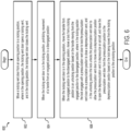
FIG. 6 is an illustration of a method of controlling pressurization and depressurization of an aircraft. - Turning now to
FIG. 1 , anaircraft door 100 is illustrated. Theaircraft door 100 is part of an aircraft that can seal or open an entry/exit into the aircraft. For example, theaircraft door 100 is moveable to a first position to permit a user to enter or exit the aircraft, and a second position to seal the aircraft and disallow the user from entering or exiting the aircraft. Theaircraft door 100 includes anaircraft pressurization system 118 that comprises apressurization vent door 106 and alocking vent door 112. Theaircraft pressurization system 118 is configured to allow pressurization in a first configuration and prevent pressurization in a second configuration to enhance safety and comply with certain regulations. For example, theaircraft pressurization system 118 separates the locking vent door 112 (e.g., a means to pressure lock), and the pressurization vent door 106 (e.g., a means of preventing pressurization of the aircraft). As will be explained in further detail, the separation of thepressurization vent door 106 and thelocking vent door 112 can provide enhanced operations including flexible positioning and safety. Furthermore, some examples can lock ahandle 102 and prevent opening of vent(s) (e.g., depressurization vent) on the ground when there is a pressure differential that could cause damage to interior parts of an aircraft (e.g., door, electronic components, etc.), and/or potential injury. - The
pressurization vent door 106 is moveable between a pressurization position to close a depressurization vent to allow the aircraft to be pressurized, and a depressurization position to open the depressurization vent to depressurize the aircraft. Thepressurization vent door 106 can be biased via a biasing mechanism (e.g., springs) towards the depressurization position (e.g., opens the depressurization vent). As described below, thepressurization vent door 106 is interlocked with thelocking vent door 112 to prevent movement of thepressurization vent door 106 from the pressurization position to the depressurization position when a pressure differential (e.g., between an interior and exterior air pressure) meets a threshold. For example, if a pressure difference between an interior of the aircraft and an exterior of the aircraft meets a threshold, thepressurization vent door 106 may be locked by thelocking vent door 112 to prevent rapid depressurization of a cabin of the aircraft. Doing so can enhance safety while also facilitating design. In this example, thepressurization vent door 106 is in the pressurization position. - The
pressurization vent door 106 is releasably connected with a hook orcatch 108. The hook orcatch 108 is movable between a locking position to engage with thepressurization vent door 106 to lock thepressurization vent door 106 into the pressurization position, and an unlocking position to unlock thepressurization vent door 106 to allow thepressurization vent door 106 to move into the depressurization position. For example, the hook orcatch 108 can form a groove that a portion of thepressurization vent door 106 is disposed within when the hook orcatch 108 is in the locking position and thepressurization vent door 106 is in the pressurization position. In doing so, the hook orcatch 108 is secured to thepressurization vent door 106 to prevent thepressurization vent door 106 from moving to the depressurization position. When the hook orcatch 108 is moved from the locking position to the unlocking position (e.g., rotated upward) the hook orcatch 108 releases thepressurization vent door 106 so that thepressurization vent door 106 is free to move and open (e.g., rotates outwardly or inwardly) to the depressurization position. In the depressurization position, the depressurization vent is exposed so that air pressure inside the aircraft and outside the aircraft equalizes (i.e., depressurization of the aircraft cabin occurs). - The
locking vent door 112 is configured to open inwardly towards an interior of the aircraft. For example, a top portion of thelocking vent door 112 can rotate inwardly while a bottom portion of thelocking vent door 112 remains fixed so that the top portion rotates around the bottom portion. Thelocking vent door 112 can be firmly held in the closing position (e.g., a close position) by an air pressure inside the aircraft. For example, if the interior air pressure inside the aircraft is greater than an exterior air pressure of the aircraft, thelocking vent door 112 can be firmly held and/or biased in the closing position. Thus, if the interior air pressure is significantly greater than the exterior air pressure (e.g., the pressure difference between the interior air pressure and the exterior air pressure meets a threshold), thelocking vent door 112 cannot be moved into the opening position and remains in the closing position. In the closing position, thelocking vent door 112 abuts aportion 110 of ashaft 122 of thehandle 102, thus preventing downward rotation of thehandle 102 alongarrow 114 to prevent thehandle 102 from moving into the disengaged position. That is, rotation of thehandle 102 rotates theshaft 122. If theshaft 122 cannot rotate downward due to theportion 110 abutting thelocking vent door 112, thehandle 102 cannot rotate downward as well. Thus, when thelocking vent door 112 is in the closing position, thehandle 102 is secured in the engaged position so that the hook orcatch 108 is in the locking position and thehandle 102 is prevented from moving into the disengaged position. When thelocking vent door 112 is in the opening position, thehandle 102 is moveable to a disengaged position. - In some examples, the
aircraft pressurization system 118 includes acover 120 attached to thelocking vent door 112. Thecover 120 covers several elements, including thehandle 102, theshaft 122, theportion 110 and the lockingvent door 112. Thecover 120 is removed when the handle is pulled to open the door. For example, thecover 120 is coupled with the lockingvent door 112 so that movement of thecover 120 moves the lockingvent door 112 between the opening position and the closing position. As noted above, in some examples the lockingvent door 112 cannot be moved from the opening position to the closing position when the pressure difference between the interior air pressure and the exterior air pressure meets the threshold. In such examples, thecover 120 cannot be moved since the lockingvent door 112 cannot be moved, thus inhibiting movement of thecover 120. As discussed below, doing so prohibits thehandle 102 from moving and thepressurization vent door 106 cannot be moved into the depressurization position. - If a pressure difference does not meet the threshold, the locking
vent door 112 is moveable (e.g., can be moved from the closing position to the opening position). Thecover 120 can be thus moved to expose thehandle 102, lockingvent door 112,portion 110,shaft 122 and thepressurization vent door 106. Furthermore, movement of thecover 120 rotates the lockingvent door 112 to the opening position due tointerconnections 142 between thecover 120 and the lockingvent door 112. Theinterconnection 142 is a flexible link that runs from the center of thecover 120 to the top of the lockingvent door 112 that when pulled, causes the lockingvent door 112 to rotate along a lower hinge line of the lockingvent door 112. If the lockingvent door 112 is unable to be opened due the pressure difference, thecover 120 cannot be moved. When the lockingvent door 112 rotates to the opening position (e.g., opens inwardly towards an interior of the aircraft) based on thecover 120 moving, the lockingvent door 112 no longer abuts theportion 110 of theshaft 122 of thehandle 102. - Since the
portion 110 of theshaft 122 no longer abuts the lockingvent door 112, thehandle 102 is no longer locked in place and can be freely moved to the disengaged position from the engaged position. Thehandle 102 can be manually rotated. When thehandle 102 moves into the disengaged position, cranks 124 are rotated to move the hook or catch 108 into the opening position (e.g., unlocking position), permitting thepressurization vent door 106 to automatically open due to the pressure difference and equalize the interior air pressure and the exterior air pressure. Thus, thehandle 102 controls the hook or catch 108. - When the
handle 102 is moved from the current illustrated engaged position to the disengaged position (e.g., downward) alongarrow 114, thehandle 102 moves (e.g., rotates) the hook or catch 108 into the unlocking position to unlock thepressurization vent door 106 from the hook or catch 108. When thepressurization vent door 106 is unlocked, thepressurization vent door 106 can move into the depressurization position under the influence of the pressure difference. That is, thepressurization vent door 106 rotates towards an outside of the aircraft and is pushed open by the internal air pressure. Since the external air pressure is less than the internal air pressure, the internal pressure is able to move thepressurization vent door 106 to the open position. For example, on landing the above operations can be executed to open thepressurization vent door 106 and equalize pressure. - In this example, the locking
vent door 112 will rotate downward pulled open by removing thecover 120 over the lockingvent door 112. If the internal pressure is too high, thecover 120 will not be removed and thehandle 102 will remain locked out to avoid depressurization when the pressure difference is significantly high. In some examples, a spring or small latch can be added to a hinge line of the lockingvent door 112 to tune a value of the pressure difference that will permit opening of the lockingvent door 112, and thus when the hook or catch 108 will be disengaged. The spring or small latch can also hold the hook or catch 108 closed once the hook or catch 108 is in the locking position. In some examples and depending on the configuration and loads, an additional feature to hold the lockingvent door 112 open until the lockingvent door 112 is manually closed is possible. - The positions of the
pressurization vent door 106 and the lockingvent door 112 are flexible as well. For example, in some examples the lockingvent door 112 and thepressurization vent door 106 can be located off theaircraft door 100 in a sidewall of the aircraft that supports theaircraft door 100. In some examples, thepressurization vent door 106 can be located beneath the illustrated window in areas that typically would not be able to accommodate thepressurization vent door 106 since thepressurization vent door 106 opens outwardly. -
FIGS. 2A-2B illustrates aprocess 200 to close an aircraft door and enable pressurization in an aircraft. Theprocess 200 is generally implemented by any of the examples described herein and can be applied to for example the aircraft door 100 (FIG. 1 ). - In a
first portion 222 of theprocess 200, a lockingvent door 208 is in an opening position and is thus not visible. Rather, alockout vent 210 is illustrated that the lockingvent door 208 will cover (explained below). A hook or catch 204 is further in an unlocking position. Ahandle 206 is in a disengaged position. A pressurization vent door 214 (not yet illustrated) is in a depressurization position to open adepressurization vent 202 to depressurize the aircraft. - In a
second portion 224 of theprocess 200, the lockingvent door 208 is moved towards a closing position to cover thelockout vent 210. Thehandle 206 is moved towards the locking position to rotate thecranks 230 into a closed position and position the hook or catch 204 into a locking position. Thus, thehandle 206 is rotated to an engaged position (e.g., a close latched and locked position). - Turning now to
FIG. 2B , in athird portion 226 of theprocess 200 is illustrated. InFIG. 2B , thehandle 206 is closed to abut against the locking vent door 208 (e.g., form a lower handle pressure lock). For example, aportion 212 of thehandle 206 abuts against the lockingvent door 208. The lockingvent door 208 is now in the closing position and thehandle 206 is in the engaged position. - In a
fourth portion 228 of theprocess 200, pins 260 are removed from thepressurization vent door 214 to allow the lockingvent door 208 to move to the closing position (e.g., locking position). Thepressurization vent door 214 is closed, covering and sealing thedepressurization vent 202. The pins are then inserted into thepressurization vent door 214 and hook or catch 204 locks thepressurization vent door 214 into a pressurization position (e.g., a closed position). At this time, a handle cover (not illustrated) can also be replaced and coupled with the lockingvent door 208. -
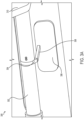
FIGS. 3A-3C illustrates apressure locking system 300. Thepressure locking system 300 is generally implemented by any of the examples described herein and can be applied to for example the aircraft door 100 (FIG. 1 ) and/or in conjunction with theprocess 200. Thepressure locking system 300 may be readily substituted for theportion 110 of theshaft 122 of thehandle 102, and the locking vent door 112 (FIG. 1 ). -
FIG. 3A illustrates a locked state of thepressure locking system 300. A lockingvent door 306 includes afirst protrusion 308. Ashaft 302 of ahandle 310 includes asecond protrusion 304 that interlocks with thefirst protrusion 308. In some examples, when a pressure difference between an internal air pressure internal to the aircraft and an external air pressure external to the aircraft meets a threshold, the lockingvent door 306 is held firmly into a closed position as illustrated, and the first andsecond protrusions handle 310 firmly in place (e.g., handle 310 cannot be rotated downward) and a cover (not illustrated) covering thehandle 310. If the internal pressure is too high, a cover will not be able to be removed and thehandle 310 will remain locked out. A pressurization vent door will be physically locked out if the lockingvent door 306 is closed, thehandle 310 shaft will bear on to the lock out feature preventing rotation of thehandle 310 and the pressurization vent door. Most door vents are considered locked when the handle force to open is above approximately 3001bs (i.e., 1.334,47 N), but may not be locked out by a shear or bearing connection. -
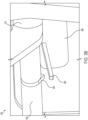
FIG. 3B illustrated an unlocked state of thepressure locking system 300. When the pressure difference does not meet the threshold, the lockingvent door 306 can rotate downward pulled open by removing a cover (not illustrated) covering thehandle 310. The first andsecond protrusions vent door 306 and place the lockingvent door 306 into an opening position. Thehandle 310 can now be rotated to open a pressurization vent door as discussed above. In some examples, a spring or small latch can be added to a hinge line of the lockingvent door 306 to tune at what pressure a lock locking the pressurization vent door will be disengaged, and also hold the pressurization vent door closed once the lock and pressurization vent door are in proper positions. In some embodiments, depending on the configuration and loads, an additional feature to lock the lockingvent door 306 open until the lockingvent door 306 is manually closed is implemented. -
FIG. 3C illustrates an intermediary state between a locked state of the pressure locking system 300 (FIG. 3A ) and an unlocked state of the pressure locking system 300 (FIG. 3B ). As illustrated, the first andsecond protrusions -
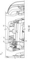
FIGS. 4A-4B illustrate apressure regulation system 400. Thepressure regulation system 400 is generally implemented by any of the examples described herein and can be applied to for example the aircraft door 100 (FIG. 1 ), in conjunction with theprocess 200 and/or in conjunction with the pressure locking system 300 (FIGS 3A-3C ). - As illustrated in
FIG. 4A , ahandle 402 is connected with a hook or catch 406 viacrank 408. The hook or catch 406 locks thepressurization vent door 404. When thehandle 402 rotates to open thepressurization vent door 404, thehandle 402 direct drives the hook or catch 406 through thecrank 408 releasing the pressurization vent door 404 (e.g., an outwardly opening vent), allowing thepressurization vent door 404 to rotate open freely. Thepressurization vent door 404 will be spring loaded open. Removeable pins 420 are also illustrated to close thepressurization vent door 404. - The
pressurization vent door 404 will stay open until manually closed. Doing so prevents pressurization of an aircraft and provides a required sequencing. The pressurization vent door 404 (e.g., a means to prevent pressurization) cannot be closed until the door is closed, latched, and locked by means of the latches of the hook or catch 406 are in place on thepressurization vent door 404 to secure thepressurization vent door 404 closed in a pressurization position. - During closing of the
pressurization vent door 404, a pin on thepressurization vent door 404 will be removed then replaced latching thepressurization vent door 404 in the pressurization position (e.g., the hooks will be in the closed position) - In some examples, to facilitate ice breaking, the hook or catch 406 can have added kicker(s) to aid in biasing the
pressurization vent door 404 open. In some examples, a spring force of thepressurization vent door 404 can be tuned to provide enough opening force to overcome restraining elements such as ice. In examples, a combination of the added kickers and spring force can be used. -
FIG. 4B illustrates an example where thehandle 402 is in the disengaged position. The hook or catch 406 has released thepressurization vent door 404 and is able to freely move into the depressurization position to depressurize the aircraft. -
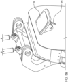
FIGS. 5A-5D illustrate a modifiedaircraft pressurization system 500.FIGS. 5A-5D is generally implemented by any of the examples described herein and can be applied to for example the aircraft door 100 (FIG. 1 ), in conjunction with theprocess 200 and/or in conjunction with the pressure locking system 300 (FIGS 3A-3C ), and/or in conjunction with pressure regulation system 400 (FIGS. 4A-4B ). - The modified
aircraft pressurization system 500 has a same function as the aircraft pressurization system 118 (FIG. 1 ), but a lockingvent door 504 is positioned in thepressurization vent door 502 and locks out a shaft 508 (e.g., a connection mechanism) of a hook or catch 506 rather locking a shaft of ahandle 510 directly. In this example, a shear lock is formed between theshaft 508 and the lockingvent door 504. Thus, the lockingvent door 504 is pressed into a locked position when a pressure difference between an internal air pressure of an aircraft and an external air pressure of the aircraft meets a threshold. When the lockingvent door 504 is in the closed position, the lockingvent door 504 abuts against a portion of theshaft 508 to form the shear lock and prevent rotation of the hook or catch 506 as well as thehandle 510. - As illustrated in
FIG. 5B , when the pressure difference fails to meet the threshold, the lockingvent door 504 can be moved into an opening position to disengage the shear lock, thereby permitting thepressurization vent door 502 to move into the depressurization position from the pressurization position. Theshaft 508 may then be rotated allowing the hook or catch 506 to rotate. Thepressurization vent door 502 is then rotatable into a depressurization position to depressurize the aircraft. The lockingvent door 504 rotates with thepressurization vent door 502. Aprotrusion 504a of the lockingvent door 504 is illustrated. The protrusion can form part of the shear lock and abuts theshaft 508 to lock theshaft 508 into place and prevent rotation of theshaft 508. -
FIG. 5C illustrates when the pressure difference fails to meet the threshold, and the shear lock is initially disengaged. Theprotrusion 504a disengages theshaft 508. At this time, thehandle 510 can be freely rotated to a disengaged position. When thehandle 510 moves to the disengaged position, the hook or catch 506 can be rotated to the unlocking position to permit thepressurization vent door 502 to open into the depressurization position. -
FIG. 5D illustrates when the shear lock is disengaged and thehandle 510 is rotated to the disengaged position. When thehandle 510 moves to the disengaged position, the hook or catch 506 is rotated to the unlocking position to permit thepressurization vent door 502 to open into the depressurization position. -
FIG. 6 shows amethod 600 of controlling pressurization and depressurization of an aircraft. Themethod 600 is generally implemented by any of the examples described herein, for example, the aircraft door 100 (FIG. 1 ), in conjunction with theprocess 200 and/or in conjunction with the pressure locking system 300 (FIGS 3A-3C ), in conjunction with pressure regulation system 400 (FIGS. 4A-4B ), and/or modified aircraft pressurization system 500 (FIGS. 5A-5D ). Some embodiments may include some electrical monitoring. - Illustrated
processing block 602 moves a locking vent door from an opening position to a closing position, where in the opening position, the locking vent door opens a lockout vent, and in the closing position, the locking vent door closes the locking vent. When the locking vent door is in the closing position, illustratedprocessing block 604 prohibits movement of a handle from an engaged position to a disengaged position. - When the locking vent door is in the opening position illustrated
processing block 606 moves the handle from the engaged position to the disengaged position. Further,processing block 606 moves a lock from a locking position to an unlocking position based on the handle moving from the engaged position to the disengaged position, where in the locking position the lock engages with a pressurization vent door to lock the pressurization vent door into a pressurization position to close a depressurization vent, and in the unlocking position the lock unlocks the pressurization vent door to allow the pressurization vent door to move into a depressurization position to open the depressurization vent to depressurize an aircraft. Further,processing block 606 moves the pressurization vent door from the pressurization position to the depressurization position based on the lock being moved from the locking position to the unlocking position. - Further, the disclosure comprises additional examples as detailed in the following clauses below.
- Clause 1. An aircraft comprising:
- a pressurization vent door that is moveable between a pressurization position to close a depressurization vent to allow the aircraft to be pressurized, and a depressurization position to open the depressurization vent to depressurize the aircraft;
- a locking vent door that when moved to be open in an opening position opens a lockout vent, and when moved to be closed in a closing position closes the lockout vent; and
- a handle that controls the pressurization vent door and is moveable to an engaged position to control the pressurization vent door to be in the pressurization position, and a disengaged position to control the pressurization vent door to be in the depressurization position, the handle being releasably connected with the locking vent door,
- wherein the handle is releasably connected with the locking vent door so that:
- when the locking vent door is in the closing position, the handle is secured in the engaged position so that the handle is prevented from moving into the disengaged position, and
- when the locking vent door is in the opening position, the handle is moveable to the disengaged position to permit the pressurization vent door to be in the depressurization position.
- Clause 2. The aircraft of Clause 1, wherein:
- an exterior air pressure is applied to the locking vent door from an exterior of the aircraft,
- an interior air pressure is applied to the locking vent door from an interior of the aircraft, and
- the locking vent door is prevented from being moved from the closing position when a pressure difference between the interior air pressure and the exterior air pressure meets a threshold.
- Clause 3. The aircraft of Clause 1, further comprising a cover coupled with the locking vent door so that movement of the cover moves the locking vent door between the opening position and the closing position.
- Clause 4. The aircraft of Clause 1, further comprising a protrusion on the locking vent door and that forms a shear lock with the handle to prevent the handle from moving to the disengaged position when the locking vent door is in the closing position.
- Clause 5. The aircraft of Clause 1, wherein the opening position and the closing position of the locking vent door are located within an interior of the aircraft.
- Clause 6. The aircraft of Clause 1, wherein the locking vent door is positioned away from the pressurization vent door
- Clause 7. The aircraft of Clause 1, further comprising:
- a hook or catch movable between a locking position to engage with the pressurization vent door to lock the pressurization vent door into the pressurization position, and an unlocking position to unlock the pressurization vent door to allow the pressurization vent door to move into the depressurization position,
- wherein when the locking vent door is in the closing position, the handle is secured in the engaged position so that the hook or catch is in the locking position and the handle is prevented from moving into the disengaged position, and
- further wherein when the locking vent door is in the opening position, the handle is moveable to the disengaged position to move the hook or catch into the unlocking position.
- Clause 8. The aircraft of Clause 1, wherein the pressurization vent door rotates towards an interior of the aircraft or towards an exterior of the aircraft.
- Clause 9. The aircraft of Clause 1, further comprising:
- an aircraft door that is moveable to a first position to permit a user to enter or exit the aircraft, and a second position to seal the aircraft and disallow the user from entering or exiting the aircraft; and
- a sidewall that supports the aircraft door;
- wherein one or more of the pressurization vent door or the locking vent door are disposed in the sidewall at a position away from the aircraft door.
- Clause 10. The aircraft of Clause 1, wherein the locking vent door is positioned in the pressurization vent door.
- Clause 11. A method comprising:
- moving a locking vent door from an opening position to a closing position, wherein in the opening position, the locking vent door opens a lockout vent, and in the closing position, the locking vent door closes the lockout vent;
- when the locking vent door is in the closing position, prohibiting movement of a handle from an engaged position to a disengaged position; and
- when the locking vent door is in the opening position,
- moving the handle from the engaged position to the disengaged position to permit a pressurization vent door to be in a depressurization position; and
- moving the pressurization vent door from a pressurization position to the depressurization position based on the handle being moved from the engaged position to the disengaged position, wherein in the pressurization position the pressurization vent door closes a depressurization vent, and in the depressurization position the pressurization vent door opens the depressurization vent to depressurize an aircraft.
- Clause 12. The method of Clause 11, further comprising:
- preventing movement of the locking vent door from the closing position when a pressure difference between an interior air pressure and an exterior air pressure meets a threshold,
- wherein the exterior air pressure is applied to the locking vent door from an exterior of the aircraft,
- wherein the interior air pressure is applied to the locking vent door from an interior of the aircraft.
- Clause 13. The method of Clause 11, further comprising:
moving a cover coupled to the locking vent door so that movement of the cover moves the locking vent door between the opening position and the closing position. - Clause 14. The method of Clause 11, further comprising:
forming, with a protrusion of the locking vent door, a shear lock with the handle to prevent the handle from moving to the disengaged position when the locking vent door is in the closing position. - Clause 15. The method of Clause 11, wherein the opening position and the closing position of the locking vent door are located within an interior of the aircraft.
- Clause 16. The method of Clause 11, wherein the locking vent door is positioned away from the pressurization vent door
- Clause 17. The method of Clause 11, further comprising:
moving a hook or catch from a locking position to an unlocking position based on the handle moving from the engaged position to the disengaged position, wherein in the locking position the hook or catch engages with the pressurization vent door to lock the pressurization vent door into the pressurization position and in the unlocking position the hook or catch unlocks the pressurization vent door to allow the pressurization vent door to move into the depressurization position. - Clause 18. The method of Clause 11, wherein the pressurization vent door rotates towards an interior of the aircraft or towards an exterior of the aircraft.
- Clause 19. The method of Clause 11, further comprising:
- moving an aircraft door to a first position to permit a user to enter or exit the aircraft; and
- moving the aircraft door to a second position to seal the aircraft and disallow the user from entering or exiting the aircraft,
- wherein a sidewall that supports the aircraft door;
- wherein one or more of the pressurization vent door or the locking vent door are disposed in the sidewall at a position away from the aircraft door.
- Clause 20. The method of Clause 11, wherein the locking vent door is positioned in the pressurization vent door.
- Clause 21. The aircraft of Clause 1, further comprising:
- a connection mechanism to connect the handle and the locking vent door; and
- a protrusion on the locking vent door that forms a shear lock with the connection mechanism to prevent the handle from moving to the disengaged position when the locking vent door is in the closing position.
- Clause 22. The method of Clause 1, further comprising:
- connecting the handle and the locking vent door with a connection mechanism connects; and
- forming a shear lock with a protrusion on the locking vent door and the connection mechanism to prevent the handle from moving to the disengaged position when the locking vent door is in the closing position.
- Example sizes/models/values/ranges can have been given, although examples are not limited to the same. Arrangements can be shown in block diagram form in order to avoid obscuring examples, and also in view of the fact that specifics with respect to implementation of such block diagram arrangements are highly dependent upon the computing system within which the example is to be implemented, i.e., such specifics should be well within purview of one skilled in the art. The term "coupled" can be used herein to refer to any type of relationship, direct or indirect, between the components in question, and can apply to electrical, mechanical, fluid, optical, electromagnetic, electromechanical, or other connections. In addition, the terms "first", "second", etc. can be used herein only to facilitate discussion, and carry no particular temporal or chronological significance unless otherwise indicated.
- As used in this application and in the claims, a list of items joined by the term "one or more of" can mean any combination of the listed terms. For example, the phrases "one or more of A, B, or C" can mean A; B; C; A and B; A and C; B and C; or A, B, and C.
- Those skilled in the art will appreciate from the foregoing description that the broad techniques of the examples can be implemented in a variety of forms. Therefore, while the examples have been described in connection with particular examples thereof, the scope of protection is determined by the appended claims.
Claims (15)
- An aircraft comprising:a pressurization vent door (106) that is moveable between a pressurization position to close a depressurization vent to allow the aircraft to be pressurized, and a depressurization position to open the depressurization vent to depressurize the aircraft;a locking vent door (112) that when moved to be open in an opening position opens a lockout vent, and when moved to be closed in a closing position closes the lockout vent; anda handle (102) that controls the pressurization vent door (106) and is moveable to an engaged position to control the pressurization vent door (106) to be in the pressurization position, and a disengaged position to control the pressurization vent door (106) to be in the depressurization position, the handle (102) being releasably connected with the locking vent door (112),wherein the handle (102) is releasably connected with the locking vent door (112) so that:when the locking vent door (112) is in the closing position, the handle (102) is secured in the engaged position so that the handle (102) is prevented from moving into the disengaged position, andwhen the locking vent door (112) is in the opening position, the handle (102) is moveable to the disengaged position to permit the pressurization vent door (106) to be in the depressurization position.
- The aircraft of claim 1, wherein:an exterior air pressure is applied to the locking vent door (112) from an exterior of the aircraft,an interior air pressure is applied to the locking vent door (112) from an interior of the aircraft, andthe locking vent door (112) is configured to be firmly held and/or biased in the closing position by the air pressure inside the aircraft when a pressure difference between the interior air pressure and the exterior air pressure meets a threshold.
- The aircraft of any one of claims 1 or 2, further comprising a cover (120) coupled with the locking vent door (112) so that movement of the cover (120) moves the locking vent door (112) between the opening position and the closing position.
- The aircraft of any one of claims 1 to 3, further comprising a protrusion on the locking vent door (112) and that forms a shear lock with the handle (102) to prevent the handle (102) from moving to the disengaged position when the locking vent door (112) is in the closing position.
- The aircraft of any one of claims 1 to 4, wherein the opening position and the closing position of the locking vent door (112) are located within an interior of the aircraft.
- The aircraft of any one of claims 1 to 5, wherein alternatively:- the locking vent door (112) is positioned away from the pressurization vent door (106); or- the locking vent door (112) is positioned in the pressurization vent door (106).
- The aircraft of any one of claims 1 to 6, further comprising:a hook or catch (108) movable between a locking position to engage with the pressurization vent door (106) to lock the pressurization vent door (106) into the pressurization position, and an unlocking position to unlock the pressurization vent door (106) to allow the pressurization vent door (106) to move into the depressurization position,wherein when the locking vent door (112) is in the closing position, the handle (102) is secured in the engaged position so that the hook or catch (108) is in the locking position and the handle (102) is prevented from moving into the disengaged position, andfurther wherein when the locking vent door (112) is in the opening position, the handle (102) is moveable to the disengaged position to move the hook or catch (108) into the unlocking position.
- The aircraft of claim 1, wherein the pressurization vent door (106) rotates towards an interior of the aircraft or towards an exterior of the aircraft, preferably wherein the pressurization vent door (106) is configured to rotate towards an outside of the aircraft and to be pushed open by an interior air pressure from an interior of the aircraft.
- The aircraft of any one of claims 1 to 8, further comprising:an aircraft door (100) that is moveable to a first position to permit a user to enter or exit the aircraft, and a second position to seal the aircraft and disallow the user from entering or exiting the aircraft; anda sidewall that supports the aircraft door;wherein one or more of the pressurization vent door (106) or the locking vent door (112) are disposed in the sidewall at a position away from the aircraft door.
- A method of controlling pressurization and depressurization of an aircraft comprising:moving a locking vent door (112) from an opening position to a closing position, wherein in the opening position, the locking vent door (112) opens a lockout vent, and in the closing position, the locking vent door (112) closes the lockout vent;when the locking vent door (112) is in the closing position, prohibiting movement of a handle (102) from an engaged position to a disengaged position; andwhen the locking vent door (112) is in the opening position, moving the handle (102) from the engaged position to the disengaged position to permit a pressurization vent door (106) to be in a depressurization position; andmoving the pressurization vent door (106) from a pressurization position to the depressurization position based on the handle (102) being moved from the engaged position to the disengaged position, wherein in the pressurization position the pressurization vent door (106) closes a depressurization vent, and in the depressurization position the pressurization vent door (106) opens the depressurization vent to depressurize an aircraft.
- The method of claim 10, further comprising:preventing movement of the locking vent door (112) from the closing position when a pressure difference between an interior air pressure and an exterior air pressure meets a threshold,wherein the exterior air pressure is applied to the locking vent door (112) from an exterior of the aircraft,wherein the interior air pressure is applied to the locking vent door (112) from an interior of the aircraft.
- The method of any one of claims 10 or 11, further comprising:
moving a cover (120) coupled to the locking vent door (112) so that movement of the cover (120) moves the locking vent door (112) between the opening position and the closing position. - The method of any one of claims 10 to 12, further comprising:
forming, with a protrusion of the locking vent door (112), a shear lock with the handle (102) to prevent the handle (102) from moving to the disengaged position when the locking vent door (112) is in the closing position. - The method of any one of claims 10 to 13, further comprising:moving a hook or catch (108) from a locking position to an unlocking position based on the handle (102) moving from the engaged position to the disengaged position, wherein in the locking position the hook or catch (108) engages with the pressurization vent door (106) to lock the pressurization vent door (106) into the pressurization position and in the unlocking position the hook or catch (108) unlocks the pressurization vent door (106) to allow the pressurization vent door (106) to move into the depressurization position,and optionally wherein the method comprises rotatingthe pressurization vent door (106) towards an interior of the aircraft or towards an exterior of the aircraft, preferably allowing the pressurization vent door (106) to rotate towards an outside of the aircraft upon a force exerted on said pressurization vent door (106) by an interior air pressure from an interior of the aircraft.
- The method of claim 11, further comprising:moving an aircraft door (100) to a first position to permit a user to enter or exit the aircraft; andmoving the aircraft door (100) to a second position to seal the aircraft and disallow the user from entering or exiting the aircraft,wherein a sidewall that supports the aircraft door;wherein one or more of the pressurization vent door (106) or the locking vent door (112) are disposed in the sidewall at a position away from the aircraft door.
Applications Claiming Priority (1)
| Application Number | Priority Date | Filing Date | Title |
|---|---|---|---|
| US18/145,439 US12168505B2 (en) | 2022-12-22 | 2022-12-22 | Separating door venting functions isolating means to prevent pressurization and handle lockout due to high cabin pressure |
Publications (2)
| Publication Number | Publication Date |
|---|---|
| EP4397589A1 true EP4397589A1 (en) | 2024-07-10 |
| EP4397589B1 EP4397589B1 (en) | 2025-08-06 |
Family
ID=88978255
Family Applications (1)
| Application Number | Title | Priority Date | Filing Date |
|---|---|---|---|
| EP23212497.4A Active EP4397589B1 (en) | 2022-12-22 | 2023-11-28 | Separating door venting functions isolating means to prevent pressurization and handle lockout due to high cabin pressure |
Country Status (4)
| Country | Link |
|---|---|
| US (1) | US12168505B2 (en) |
| EP (1) | EP4397589B1 (en) |
| JP (1) | JP2024091557A (en) |
| CN (1) | CN118238991A (en) |
Families Citing this family (1)
| Publication number | Priority date | Publication date | Assignee | Title |
|---|---|---|---|---|
| US12391358B2 (en) * | 2023-05-09 | 2025-08-19 | The Boeing Company | Pressure differential lockout system and calibration method |
Citations (5)
| Publication number | Priority date | Publication date | Assignee | Title |
|---|---|---|---|---|
| FR2686568A1 (en) * | 1992-01-28 | 1993-07-30 | Aerospatiale | Pressurised aircraft door, making it possible to remove the internal residual pressure before opening it, and to limit the pressurisation as long as it is not completely closed |
| US20060006285A1 (en) * | 2002-09-03 | 2006-01-12 | Carsten Puschmann | Device for warning of differential pressure during the opening of a pressurized closing device pertaining to an opening in the fuselage of an aeroplane |
| US20130327892A1 (en) * | 2009-09-01 | 2013-12-12 | Textron Innovations Inc. | Aircraft Cabin Door Pressure Vent System |
| US20220126974A1 (en) * | 2019-03-12 | 2022-04-28 | Latecoere | Aircraft door having a mechanism for conditional opening along two trajectories |
| US20220135201A1 (en) * | 2020-11-05 | 2022-05-05 | The Boeing Company | Coaxial pressure lock assembly of an aircraft door |
Family Cites Families (13)
| Publication number | Priority date | Publication date | Assignee | Title |
|---|---|---|---|---|
| US4473201A (en) | 1982-10-29 | 1984-09-25 | The Boeing Company | Canopy-type aircraft cargo door and actuating mechanisms |
| US5305969A (en) | 1991-07-16 | 1994-04-26 | The Boeing Company | Aircraft door latch lock mechanism |
| US5337977A (en) | 1993-01-29 | 1994-08-16 | The Boeing Company | Vent-latch interlock assembly for an aircraft door |
| US5823473A (en) | 1995-05-15 | 1998-10-20 | The Boeing Company | Latch-lock mechanism for load carrying airplane cargo doors |
| CN1082003C (en) | 1996-08-30 | 2002-04-03 | 波音公司 | Latch-lock mechanism for load carrying airplane cargo doors |
| US5931415A (en) | 1997-05-09 | 1999-08-03 | The Boeing Company | Plug-type overwing emergency exit door assembly |
| US6454210B1 (en) | 2000-07-13 | 2002-09-24 | Wesley M. Plattner | Aircraft vent and cargo door locking mechanism |
| DE102006001685B4 (en) | 2006-01-12 | 2009-11-12 | Airbus Deutschland Gmbh | Method and system for controlling the pressure in an aircraft cabin |
| RU2482018C2 (en) | 2007-07-31 | 2013-05-20 | Б/Е Аэроспейс, Инк. | Aircraft door |
| EP2415663B1 (en) | 2010-08-05 | 2013-10-23 | Eurocopter Deutschland GmbH | Actuating mechanism for a vent door |
| FR3043058A1 (en) | 2015-11-03 | 2017-05-05 | Latecoere | AIRCRAFT EMERGENCY EXIT DOOR WITH INTEGRATED MECHANISMS AND METHOD OF OPENING / CLOSING SUCH A DOOR |
| CN207131224U (en) * | 2017-08-25 | 2018-03-23 | 浙江春风动力股份有限公司 | A kind of vehicle and its door handle mechanism, door outer handle mechanism |
| IT202000000851U1 (en) | 2020-02-21 | 2021-08-21 | Leonardo Spa | Cargo door with fail-safe locking mechanism |
-
2022
- 2022-12-22 US US18/145,439 patent/US12168505B2/en active Active
-
2023
- 2023-11-28 EP EP23212497.4A patent/EP4397589B1/en active Active
- 2023-12-20 JP JP2023214404A patent/JP2024091557A/en active Pending
- 2023-12-22 CN CN202311794401.4A patent/CN118238991A/en active Pending
Patent Citations (5)
| Publication number | Priority date | Publication date | Assignee | Title |
|---|---|---|---|---|
| FR2686568A1 (en) * | 1992-01-28 | 1993-07-30 | Aerospatiale | Pressurised aircraft door, making it possible to remove the internal residual pressure before opening it, and to limit the pressurisation as long as it is not completely closed |
| US20060006285A1 (en) * | 2002-09-03 | 2006-01-12 | Carsten Puschmann | Device for warning of differential pressure during the opening of a pressurized closing device pertaining to an opening in the fuselage of an aeroplane |
| US20130327892A1 (en) * | 2009-09-01 | 2013-12-12 | Textron Innovations Inc. | Aircraft Cabin Door Pressure Vent System |
| US20220126974A1 (en) * | 2019-03-12 | 2022-04-28 | Latecoere | Aircraft door having a mechanism for conditional opening along two trajectories |
| US20220135201A1 (en) * | 2020-11-05 | 2022-05-05 | The Boeing Company | Coaxial pressure lock assembly of an aircraft door |
Also Published As
| Publication number | Publication date |
|---|---|
| JP2024091557A (en) | 2024-07-04 |
| CN118238991A (en) | 2024-06-25 |
| US20240208634A1 (en) | 2024-06-27 |
| US12168505B2 (en) | 2024-12-17 |
| EP4397589B1 (en) | 2025-08-06 |
Similar Documents
| Publication | Publication Date | Title |
|---|---|---|
| US11299250B2 (en) | Aircraft privacy door and door frame assembly | |
| US10752331B2 (en) | Aircraft emergency exit door with integrated mechanisms and method for opening/closing such a door | |
| CA3204300C (en) | Aircraft privacy door and door frame assembly | |
| US11305860B2 (en) | Aircraft privacy door and door frame assembly | |
| EP1427904B1 (en) | Access apparatus for a cockpit of an aircraft | |
| EP4397589B1 (en) | Separating door venting functions isolating means to prevent pressurization and handle lockout due to high cabin pressure | |
| EP4011781B1 (en) | Cockpit door security system | |
| US2577697A (en) | Safety device for pressurized cabin doors | |
| EP3524510B1 (en) | Aircraft privacy door and door frame assembly | |
| US12297677B2 (en) | Reduced volume latch, lock, vent and handle mechanism for an apparatus door | |
| EP3524512B1 (en) | Aircraft privacy door and door frame assembly | |
| GB2415731A (en) | Aircraft flight deck double door access system |
Legal Events
| Date | Code | Title | Description |
|---|---|---|---|
| PUAI | Public reference made under article 153(3) epc to a published international application that has entered the european phase |
Free format text: ORIGINAL CODE: 0009012 |
|
| STAA | Information on the status of an ep patent application or granted ep patent |
Free format text: STATUS: THE APPLICATION HAS BEEN PUBLISHED |
|
| AK | Designated contracting states |
Kind code of ref document: A1 Designated state(s): AL AT BE BG CH CY CZ DE DK EE ES FI FR GB GR HR HU IE IS IT LI LT LU LV MC ME MK MT NL NO PL PT RO RS SE SI SK SM TR |
|
| STAA | Information on the status of an ep patent application or granted ep patent |
Free format text: STATUS: REQUEST FOR EXAMINATION WAS MADE |
|
| 17P | Request for examination filed |
Effective date: 20241205 |
|
| GRAP | Despatch of communication of intention to grant a patent |
Free format text: ORIGINAL CODE: EPIDOSNIGR1 |
|
| STAA | Information on the status of an ep patent application or granted ep patent |
Free format text: STATUS: GRANT OF PATENT IS INTENDED |
|
| RIC1 | Information provided on ipc code assigned before grant |
Ipc: B64C 1/00 20060101ALN20250522BHEP Ipc: B64C 1/14 20060101AFI20250522BHEP |
|
| GRAS | Grant fee paid |
Free format text: ORIGINAL CODE: EPIDOSNIGR3 |
|
| GRAA | (expected) grant |
Free format text: ORIGINAL CODE: 0009210 |
|
| STAA | Information on the status of an ep patent application or granted ep patent |
Free format text: STATUS: THE PATENT HAS BEEN GRANTED |
|
| INTG | Intention to grant announced |
Effective date: 20250610 |
|
| AK | Designated contracting states |
Kind code of ref document: B1 Designated state(s): AL AT BE BG CH CY CZ DE DK EE ES FI FR GB GR HR HU IE IS IT LI LT LU LV MC ME MK MT NL NO PL PT RO RS SE SI SK SM TR |
|
| REG | Reference to a national code |
Ref country code: GB Ref legal event code: FG4D |
|
| REG | Reference to a national code |
Ref country code: CH Ref legal event code: EP |
|
| REG | Reference to a national code |
Ref country code: IE Ref legal event code: FG4D |
|
| REG | Reference to a national code |
Ref country code: DE Ref legal event code: R096 Ref document number: 602023005463 Country of ref document: DE |
|
| P01 | Opt-out of the competence of the unified patent court (upc) registered |
Free format text: CASE NUMBER: UPC_APP_1067_4397589/2025 Effective date: 20250725 |
|
| REG | Reference to a national code |
Ref country code: NL Ref legal event code: MP Effective date: 20250806 |
|
| PG25 | Lapsed in a contracting state [announced via postgrant information from national office to epo] |
Ref country code: IS Free format text: LAPSE BECAUSE OF FAILURE TO SUBMIT A TRANSLATION OF THE DESCRIPTION OR TO PAY THE FEE WITHIN THE PRESCRIBED TIME-LIMIT Effective date: 20251206 |
|
| PGFP | Annual fee paid to national office [announced via postgrant information from national office to epo] |
Ref country code: DE Payment date: 20251128 Year of fee payment: 3 |
|
| PG25 | Lapsed in a contracting state [announced via postgrant information from national office to epo] |
Ref country code: NO Free format text: LAPSE BECAUSE OF FAILURE TO SUBMIT A TRANSLATION OF THE DESCRIPTION OR TO PAY THE FEE WITHIN THE PRESCRIBED TIME-LIMIT Effective date: 20251106 |
|
| REG | Reference to a national code |
Ref country code: LT Ref legal event code: MG9D |
|
| PG25 | Lapsed in a contracting state [announced via postgrant information from national office to epo] |
Ref country code: PT Free format text: LAPSE BECAUSE OF FAILURE TO SUBMIT A TRANSLATION OF THE DESCRIPTION OR TO PAY THE FEE WITHIN THE PRESCRIBED TIME-LIMIT Effective date: 20251209 |
|
| PG25 | Lapsed in a contracting state [announced via postgrant information from national office to epo] |
Ref country code: FI Free format text: LAPSE BECAUSE OF FAILURE TO SUBMIT A TRANSLATION OF THE DESCRIPTION OR TO PAY THE FEE WITHIN THE PRESCRIBED TIME-LIMIT Effective date: 20250806 |
|
| PG25 | Lapsed in a contracting state [announced via postgrant information from national office to epo] |
Ref country code: HR Free format text: LAPSE BECAUSE OF FAILURE TO SUBMIT A TRANSLATION OF THE DESCRIPTION OR TO PAY THE FEE WITHIN THE PRESCRIBED TIME-LIMIT Effective date: 20250806 Ref country code: NL Free format text: LAPSE BECAUSE OF FAILURE TO SUBMIT A TRANSLATION OF THE DESCRIPTION OR TO PAY THE FEE WITHIN THE PRESCRIBED TIME-LIMIT Effective date: 20250806 |
|
| PGFP | Annual fee paid to national office [announced via postgrant information from national office to epo] |
Ref country code: FR Payment date: 20251125 Year of fee payment: 3 |
|
| PG25 | Lapsed in a contracting state [announced via postgrant information from national office to epo] |
Ref country code: GR Free format text: LAPSE BECAUSE OF FAILURE TO SUBMIT A TRANSLATION OF THE DESCRIPTION OR TO PAY THE FEE WITHIN THE PRESCRIBED TIME-LIMIT Effective date: 20251107 |
|
| PG25 | Lapsed in a contracting state [announced via postgrant information from national office to epo] |
Ref country code: SE Free format text: LAPSE BECAUSE OF FAILURE TO SUBMIT A TRANSLATION OF THE DESCRIPTION OR TO PAY THE FEE WITHIN THE PRESCRIBED TIME-LIMIT Effective date: 20250806 |
|
| PG25 | Lapsed in a contracting state [announced via postgrant information from national office to epo] |
Ref country code: LV Free format text: LAPSE BECAUSE OF FAILURE TO SUBMIT A TRANSLATION OF THE DESCRIPTION OR TO PAY THE FEE WITHIN THE PRESCRIBED TIME-LIMIT Effective date: 20250806 |
|
| PG25 | Lapsed in a contracting state [announced via postgrant information from national office to epo] |
Ref country code: PL Free format text: LAPSE BECAUSE OF FAILURE TO SUBMIT A TRANSLATION OF THE DESCRIPTION OR TO PAY THE FEE WITHIN THE PRESCRIBED TIME-LIMIT Effective date: 20250806 Ref country code: BG Free format text: LAPSE BECAUSE OF FAILURE TO SUBMIT A TRANSLATION OF THE DESCRIPTION OR TO PAY THE FEE WITHIN THE PRESCRIBED TIME-LIMIT Effective date: 20250806 |
|
| PG25 | Lapsed in a contracting state [announced via postgrant information from national office to epo] |
Ref country code: RS Free format text: LAPSE BECAUSE OF FAILURE TO SUBMIT A TRANSLATION OF THE DESCRIPTION OR TO PAY THE FEE WITHIN THE PRESCRIBED TIME-LIMIT Effective date: 20251106 |
|
| PG25 | Lapsed in a contracting state [announced via postgrant information from national office to epo] |
Ref country code: ES Free format text: LAPSE BECAUSE OF FAILURE TO SUBMIT A TRANSLATION OF THE DESCRIPTION OR TO PAY THE FEE WITHIN THE PRESCRIBED TIME-LIMIT Effective date: 20250806 |
|
| REG | Reference to a national code |
Ref country code: AT Ref legal event code: MK05 Ref document number: 1821572 Country of ref document: AT Kind code of ref document: T Effective date: 20250806 |
|
| PG25 | Lapsed in a contracting state [announced via postgrant information from national office to epo] |
Ref country code: RO Free format text: LAPSE BECAUSE OF FAILURE TO SUBMIT A TRANSLATION OF THE DESCRIPTION OR TO PAY THE FEE WITHIN THE PRESCRIBED TIME-LIMIT Effective date: 20250806 |
|
| PG25 | Lapsed in a contracting state [announced via postgrant information from national office to epo] |
Ref country code: SM Free format text: LAPSE BECAUSE OF FAILURE TO SUBMIT A TRANSLATION OF THE DESCRIPTION OR TO PAY THE FEE WITHIN THE PRESCRIBED TIME-LIMIT Effective date: 20250806 |
|
| PG25 | Lapsed in a contracting state [announced via postgrant information from national office to epo] |
Ref country code: DK Free format text: LAPSE BECAUSE OF FAILURE TO SUBMIT A TRANSLATION OF THE DESCRIPTION OR TO PAY THE FEE WITHIN THE PRESCRIBED TIME-LIMIT Effective date: 20250806 |
|
| PG25 | Lapsed in a contracting state [announced via postgrant information from national office to epo] |
Ref country code: AT Free format text: LAPSE BECAUSE OF FAILURE TO SUBMIT A TRANSLATION OF THE DESCRIPTION OR TO PAY THE FEE WITHIN THE PRESCRIBED TIME-LIMIT Effective date: 20250806 |
|
| PG25 | Lapsed in a contracting state [announced via postgrant information from national office to epo] |
Ref country code: IT Free format text: LAPSE BECAUSE OF FAILURE TO SUBMIT A TRANSLATION OF THE DESCRIPTION OR TO PAY THE FEE WITHIN THE PRESCRIBED TIME-LIMIT Effective date: 20250806 |
|
| PG25 | Lapsed in a contracting state [announced via postgrant information from national office to epo] |
Ref country code: CZ Free format text: LAPSE BECAUSE OF FAILURE TO SUBMIT A TRANSLATION OF THE DESCRIPTION OR TO PAY THE FEE WITHIN THE PRESCRIBED TIME-LIMIT Effective date: 20250806 |
|
| PG25 | Lapsed in a contracting state [announced via postgrant information from national office to epo] |
Ref country code: EE Free format text: LAPSE BECAUSE OF FAILURE TO SUBMIT A TRANSLATION OF THE DESCRIPTION OR TO PAY THE FEE WITHIN THE PRESCRIBED TIME-LIMIT Effective date: 20250806 Ref country code: SK Free format text: LAPSE BECAUSE OF FAILURE TO SUBMIT A TRANSLATION OF THE DESCRIPTION OR TO PAY THE FEE WITHIN THE PRESCRIBED TIME-LIMIT Effective date: 20250806 |