EP4397564A1 - System for detecting object and method for detecting object - Google Patents
System for detecting object and method for detecting object Download PDFInfo
- Publication number
- EP4397564A1 EP4397564A1 EP22863934.0A EP22863934A EP4397564A1 EP 4397564 A1 EP4397564 A1 EP 4397564A1 EP 22863934 A EP22863934 A EP 22863934A EP 4397564 A1 EP4397564 A1 EP 4397564A1
- Authority
- EP
- European Patent Office
- Prior art keywords
- region
- interest
- roi
- track
- image
- Prior art date
- Legal status (The legal status is an assumption and is not a legal conclusion. Google has not performed a legal analysis and makes no representation as to the accuracy of the status listed.)
- Pending
Links
Images





Classifications
-
- G—PHYSICS
- G06—COMPUTING OR CALCULATING; COUNTING
- G06T—IMAGE DATA PROCESSING OR GENERATION, IN GENERAL
- G06T7/00—Image analysis
-
- B—PERFORMING OPERATIONS; TRANSPORTING
- B61—RAILWAYS
- B61L—GUIDING RAILWAY TRAFFIC; ENSURING THE SAFETY OF RAILWAY TRAFFIC
- B61L23/00—Control, warning or like safety means along the route or between vehicles or trains
- B61L23/04—Control, warning or like safety means along the route or between vehicles or trains for monitoring the mechanical state of the route
- B61L23/041—Obstacle detection
-
- G—PHYSICS
- G06—COMPUTING OR CALCULATING; COUNTING
- G06T—IMAGE DATA PROCESSING OR GENERATION, IN GENERAL
- G06T7/00—Image analysis
- G06T7/60—Analysis of geometric attributes
-
- G—PHYSICS
- G06—COMPUTING OR CALCULATING; COUNTING
- G06V—IMAGE OR VIDEO RECOGNITION OR UNDERSTANDING
- G06V10/00—Arrangements for image or video recognition or understanding
- G06V10/20—Image preprocessing
- G06V10/25—Determination of region of interest [ROI] or a volume of interest [VOI]
-
- G—PHYSICS
- G06—COMPUTING OR CALCULATING; COUNTING
- G06V—IMAGE OR VIDEO RECOGNITION OR UNDERSTANDING
- G06V10/00—Arrangements for image or video recognition or understanding
- G06V10/40—Extraction of image or video features
- G06V10/62—Extraction of image or video features relating to a temporal dimension, e.g. time-based feature extraction; Pattern tracking
-
- G—PHYSICS
- G06—COMPUTING OR CALCULATING; COUNTING
- G06V—IMAGE OR VIDEO RECOGNITION OR UNDERSTANDING
- G06V20/00—Scenes; Scene-specific elements
- G06V20/50—Context or environment of the image
- G06V20/52—Surveillance or monitoring of activities, e.g. for recognising suspicious objects
- G06V20/54—Surveillance or monitoring of activities, e.g. for recognising suspicious objects of traffic, e.g. cars on the road, trains or boats
-
- G—PHYSICS
- G06—COMPUTING OR CALCULATING; COUNTING
- G06V—IMAGE OR VIDEO RECOGNITION OR UNDERSTANDING
- G06V20/00—Scenes; Scene-specific elements
- G06V20/50—Context or environment of the image
- G06V20/56—Context or environment of the image exterior to a vehicle by using sensors mounted on the vehicle
- G06V20/58—Recognition of moving objects or obstacles, e.g. vehicles or pedestrians; Recognition of traffic objects, e.g. traffic signs, traffic lights or roads
Definitions
- the present invention relates to a technology of detecting a target object in an image.
- motorman-less operation has already been realized in subway systems or new types of transportation that cause railway vehicles to travel on elevated railroads, there are no practical examples of routes where humans may enter, such as routes where there are level crossings and the like or routes in rail yards where there are workers.
- Realization of motorman-less operation requires means for detecting obstacles such as humans or vehicles that may enter tracks. Particularly, it is necessary to detect distant obstacles fast and highly precisely in order to decelerate or stop upon detection of obstacles.
- cameras and image processing are used to perform obstacle detection.
- technologies to recognize and detect objects by image processing there are general object recognition technologies with precision which has been enhanced rapidly owing to deep learning in recent years.
- the general object recognition technologies have a tendency that the precision of detecting objects with smaller pixel counts in images deteriorates.
- ROIs are limited by defining a region that needs to be monitored, in a case where the region is large or in a case where there are a plurality of regions and the regions are distributed over a wide range in an image, the image needs to be captured with a large angle of view; as a result, a captured image of a target object becomes small undesirably, and the sensing may fail.
- An object detection system detects objects in an image captured from a moving body moving on a track with a specified width.
- the system can be used for detection of obstacles of a railway vehicle travelling on a track including rails, a conveyance robot moving on a track which is a lane with a predetermined width, and the like.
- the system can be used for operation assistance, automated operation, and the like of moving bodies travelling on tracks.
- a specific explanation is given with regard to an example of a system that detects obstacles of a railway vehicle moving on rails.
- the structure gauge determines dimensional bounds defining a region around the track on which the railway vehicle is travelling and the construction of buildings, the planting of trees, or the like are prohibited in the region.
- the structure gauge is a region with a certain width L [m] centered on the center of the track on which the railway vehicle is moving. That is, both sides of the track are detection targets.
- the numerical value of the width L is predetermined for a certain track width R [m].
- the obstacle detection system sets ROIs on the basis of detection conditions required for detecting an obstacle appropriately. As a result, ROIs that enable appropriate balance of detection precision, a range of detection, a processing speed, and the like can be set.
- the track width and the structure gauge width are constant widths.
- v coordinates (ordinates) in the longitudinal direction and u coordinates (abscissas) in the lateral direction are set, with their origins at the upper left corner of an image. It can be considered that the ratios (scales) between lengths in the real world and lengths in the image do not change if v coordinates in the image of measured geographical points are the same.
- the obstacle detection system determines ROIs on the basis of a track width in an image and a predetermined coefficient. This coefficient is called an ROI coefficient.
- the ROI coefficient is based on a pixel count of a target object in an image necessary for detection, the size of the detection-target object in the real world, the input image size of an object recognition program, and a track width in the real world.
- the width of an ROI is determined as the track width R [m] multiplied by the coefficient.
- the intra-structure-gauge obstacle detection system 10 further includes a communication interface (IF) 116 that performs data communication with external devices such as another computer device, an external storage device, a camera, a microphone, or various types of sensors and an auxiliary storage device 113 that provides a non-volatile storage area using an HDD (Hard Disk Drive), a flash memory, or the like.
- IF communication interface
- the image acquiring section 101 receives an image from a monitoring camera received via the communication interface 116.
- the input image is an image including an image of a track which is a captured image of the space in an advancing direction of a railway vehicle.
- FIG. 2 schematically depicts an example of the input image.
- An input image 20 includes a track 25 extending forward from a railway vehicle.
- the track 25 extends between trees around it.
- the track 25 includes a left rail 26 and a right rail 27, and these define the width of the track 25.
- v coordinates in the longitudinal direction and u coordinates in the lateral direction are set, with their origins at the upper left corner of the input image 20.
- the ROI processing section 106 determines a plurality of ROIs, and outputs them.
- the obstacle detecting section 107 performs an obstacle detection process by using, as input, an image included in each ROI.
- the result output section 108 outputs obstacle detection results obtained by the detection by the obstacle detecting section 107.
- the intra-structure-gauge obstacle detection system 10 may be a physical computer system (one or more physical computers) or may be a system built on a group of computational resources (a plurality of computational resources) such as a cloud computing infrastructure.
- the intra-structure-gauge obstacle detection system 10 may be mobile equipment such as a smartphone or a tablet.
- the computer system or the group of computational resources includes one or more interface devices, one or more storage devices (e.g., including a main storage device and an auxiliary storage device), and one or more calculating devices.
- the programs may be installed from a program source.
- the program source may be a program distribution computer or a computer-readable storage medium (e.g., a computer-readable non-transitory storage medium).
- a program distribution computer or a computer-readable storage medium (e.g., a computer-readable non-transitory storage medium).
- a computer-readable storage medium e.g., a computer-readable non-transitory storage medium.
- FIG. 3 is a block diagram schematically depicting the configuration of the ROI processing section 106.
- An image input section 301 receives, as input, the image captured by the monitoring camera and acquired by the image acquiring section 101.
- a track detection result input section 302 receives, as input, the coordinates of the left and right rails of the track detected by the track detecting section 103.
- a detection condition input section 303 receives, as input, the detection conditions from the detection condition assessing section 102.
- FIG. 4D depicts a configuration example of a weather/time interval coefficient table 440.
- the weather/time interval coefficient table 440 manages the relation between weather/time intervals at the times of obstacle detection and coefficients.
- the weather/time interval coefficient table 440 includes a weather field 441, a time interval field 442, and a coefficient field 443.
- the weather field 441 represents weather such as fine weather or rain
- the time interval field 442 represents time intervals such as daytime or nighttime. Note that the weather field or the time interval field may represent weather or time intervals by another method.
- the coefficient field 423 represents coefficients for combinations of weather and time intervals.
- step 506 the obstacle detecting section 107 performs an obstacle detection process on all the ROIs.
- the procedure proceeds to step 508.
- the result output section 108 issues an obstacle detection alert.
- the result output section 108 may give a warning to the motorman, or in a case where the result output section 108 is connected with an operation control device of the railway vehicle, the result output section 108 may perform a process of decelerating the vehicle.
- the ROI determining section 306 determines a width r k of an ROI k which is the k-th ROI, by multiplying a width w k of the track at a geographical point at a v coordinate v k in a screen by the ROI coefficient.
- the ROI is a square.
- the v coordinate of the upper side of the ROI k is v k .
- v k is the reference ordinate value of the ROI k .
- a track 210 extends forward from the near side. That is, the track 210 extends from the lower side to the upper side of the input image.
- u coordinates increase from the left side to the right side
- v coordinates increase from the upper side to the lower side.
- the v coordinate of a geographical point where the ROI k starts being unable to cover the structure-gauge region is the v coordinate of the lower side of the ROI k .
- the v coordinate of the geographical point where the ROI k starts being unable to cover the structure-gauge region is a v coordinate v k+1 of the upper side of the following ROI k+1 .
- the track 210 On the upper side of the ROI k+1 , that is, at the v coordinate v k+1 , the track 210 has a width w k+1 , and the structure-gauge region has a width l k+1 .
- the ROI k+1 has a width r k+1 .
- the relation of l k+1 (L/R)w k+1 holds true.
- abscissa values of the ROI k there are abscissa values of the ROI k at which both the lower intersections of the two structure-gauge lines and the ROI k are positioned on the lower side of the ROI k .
- the abscissa values can be set as abscissa values of the ROI k for performing the target-object detection process.
- the v coordinate of the geographical point where the ROI k starts being unable to cover the structure-gauge region is the v coordinate v k+1 of the upper side of the following ROI k+1 . That is, the v coordinate v k+1 of the upper side of the following ROI k+1 coincides with the v coordinates of the lower intersections.
- the intersection C k+1 of the upper side of the ROI k+1 and the centerline of the track 210 has the coordinates (u k+1 , v k+1 ).
- the intersection C k+1 of the upper side of the ROI k+1 and the centerline of the track 210 has the coordinates (u k+1 , v k+1 ).
- the track 210 On the upper side of the ROI k+1 , that is, at the v coordinate v k+1 , the track 210 has the width w k+1 , and the structure-gauge region has the width l k+1 .
- the ROI k+1 has the width r k+1 .
- the fourth pattern is a case where the ROI k reaches the lower end of the screen, and an ROI 1 to the ROI k cover the entire structure-gauge region in the input image.
- the v coordinate v k where the width of the track is measured is used as the v coordinate value of the upper end of the ROI k .
- the v coordinate v k is the reference ordinate value of the ROI k .
- the v coordinate value of the upper end of the ROI k may be different from v k , for example, may be positioned higher than v k .
- the u coordinate of the center of the ROI k is determined such that the v coordinates of the intersections of the two structure-gauge lines and the left and right sides of the ROI k become the same.
- the u coordinate of the center of the ROI k and the u coordinate of the center of the track at the v coordinate v k+1 match.
- the ROI k can include the entire region of the structure-gauge region from the v coordinate v k to the v coordinate v k+1 .
- the ROI k in FIG. 8 satisfies this condition.
- the ROI determining section 306 may determine, as the u coordinate of the center of the ROI k , (u k +l k /2-r k /2 (when u k > u k+1 )) or (u k -l k /2+r k /2 (when u k ⁇ u k+1 )).
- the ROI k can include the entire region of the structure-gauge region from the v coordinate v k to the v coordinate v k+1 .
- One of the structure-gauge lines crosses the upper corner of the ROI k .
- the ROI k in FIG. 9 satisfies this condition.
- the ROI determining section 306 determines, as the u coordinate of the center of the ROI k , the u coordinate of the center of the track at the v coordinate v k .
- the ROI k can include the entire region of the structure-gauge region in the image.
- the u coordinate value of the ROI k in each pattern may be determined by a method that is different from the methods described above.
- the u coordinate of the center of the track at the v coordinate v k may be determined as the u coordinate of the center of the ROI k .
- step 611 the ROI determining section 306 increments k. Thereafter, the procedure returns to step 606, and the next ROI is determined at a new position of the v coordinate v k .
- one or more ROIs cover the structure-gauge region in an input image over the range from the far side to the near side.
- target objects can be detected in each ROI with the necessary detection precision set in the detection conditions.
- FIG. 10 depicts an example of a plurality of ROIs formed for one input image.
- three ROIs are formed for the input image 20, and the three ROIs covers the entire structure-gauge region in the input image 20.
- the three ROIs are the ROI 1 , the ROI 2 , and the ROI 3 .
- the ROI 1 and the ROI 2 are ROIs of the second pattern explained with reference to FIG. 8
- the ROI 3 is an ROI of the fourth pattern.
- Each ROI represents a detection limit of a region within which target objects can be detected.
- the ROI determining section 306 determines the v coordinate v 1 of the ROI 1 , which is the first ROI, and the ROI coefficient. From the ROI coefficient and the track width at the v coordinate v 1 , the length of one side of the ROI 1 is determined. On the upper side of the ROI 1 , that is, at the v coordinate v 1 , the track 210 has a width w 1 , and the structure-gauge region has a width l 1 . The ROI 1 has a width r 1 .
- the ROI determining section 306 adjusts the u coordinate of the ROI 1 as necessary, and assesses the relation between the ROI 1 and the structure gauge.
- the relation between the ROI 1 and the track 210 corresponds to the second pattern.
- the left structure-gauge line 220A of the track 210 crosses the upper side and the left side of the ROI 1 .
- the right structure-gauge line 220B of the track 210 crosses the upper side and the right side of the ROI 1 .
- the ROI determining section 306 performs a process of forming the next ROI 2 at the v coordinate v 2 .
- the formation of the ROI 2 is similar to the formation of the ROI 1 described above.
- the track 210 On the upper side of the ROI 2 , that is, at the v coordinate v 2 , the track 210 has a width w 2 , and the structure-gauge region has a width l 2 .
- the ROI 2 has a width r 2 .
- the structure-gauge lines 220A and 220B cross the left and right sides of the ROI 2 at a v coordinate v 3 .
- the ROI 3 is formed at the v coordinate v 3 .
- the track 210 has a width w 3
- the structure-gauge region has a width l 3 .
- the ROI 3 has a width r 3 .
- the relation between the ROI 3 and the structure-gauge region corresponds to the fourth pattern.
- the u coordinate of the center of the ROI 3 is determined in such a manner as to coincide with the u coordinate of the center of the track 210 at the v coordinate v 3 .
- the present invention is not limited to the embodiments described above, and includes various modification examples.
- the embodiments described above are explained in detail for explaining the present invention in an easy-to-understand manner, and the present invention is not necessarily limited to those including all constituent elements explained..
- some of constituent elements of each embodiment can also have other constituent elements additionally, be removed, or be replaced.
- each constituent element, function, processing section, or the like described above may.be partially or entirely realized by hardware by, for example, designing it with an integrated circuit.
- each constituent element, function, and the like described above may be realized by software by a processor interpreting and executing a program to realize each function.
- Information such as a program, a table or a file to realize each function can be placed on a recording device such as a memory, a hard disk, or an SSD (Solid State Drive) or a recording medium such as an IC card or an SD card.
- control lines and information lines are ones that are considered to be necessary for explanation, and all control lines and information lines that are necessary for products are not necessarily depicted. It may be considered that, in practice, almost all constituent elements are interconnected.
Landscapes
- Engineering & Computer Science (AREA)
- Physics & Mathematics (AREA)
- General Physics & Mathematics (AREA)
- Theoretical Computer Science (AREA)
- Multimedia (AREA)
- Computer Vision & Pattern Recognition (AREA)
- Mechanical Engineering (AREA)
- Geometry (AREA)
- Image Analysis (AREA)
- Train Traffic Observation, Control, And Security (AREA)
- Image Processing (AREA)
Abstract
Description
- The present application claims the priority of
Japanese Patent Application No. 2021-141404, which is a Japanese application filed on August 31, 2021 - The present invention relates to a technology of detecting a target object in an image.
- As means for cost reduction and service improvement in the railway transportation business, motorman-less operation of trains has been attracting attention. For railway operators, labor costs of motormen and costs required for training motormen are considerable, and expectations of the railway operators for motorman cost reduction realized by motorman-less operation are high. In addition, in terms of service, since constraints regarding assignment of motormen will be removed, the degree of freedom of operation improves, and also improvement of convenience for users owing to highly frequent operation can also be expected.
- Although motorman-less operation has already been realized in subway systems or new types of transportation that cause railway vehicles to travel on elevated railroads, there are no practical examples of routes where humans may enter, such as routes where there are level crossings and the like or routes in rail yards where there are workers. Realization of motorman-less operation requires means for detecting obstacles such as humans or vehicles that may enter tracks. Particularly, it is necessary to detect distant obstacles fast and highly precisely in order to decelerate or stop upon detection of obstacles.
- In cases considered in the present invention, cameras and image processing are used to perform obstacle detection. As technologies to recognize and detect objects by image processing, there are general object recognition technologies with precision which has been enhanced rapidly owing to deep learning in recent years. However, the general object recognition technologies have a tendency that the precision of detecting objects with smaller pixel counts in images deteriorates.
- A technology in
JP-2019-181996-A - It is difficult with the general object recognition technologies to detect objects with smaller pixel counts in images. Due to restrictions of computational costs in performing real-time processing, input image sizes are restricted to certain sizes such as 608 × 608 or 416 × 416 in the general object recognition technologies. Accordingly, even if a high-resolution image is captured, it is downsized undesirably when used as input in the general object recognition technologies.
- If the image is downsized, it becomes difficult to detect objects with smaller pixel counts, such as distant obstacles. One conceivable measure for detecting objects with smaller pixel counts is to set particular regions in an image as ROIs (Regions Of Interest), and treat only the ROIs as processing targets. However, since the region outside the ROIs is excluded from processing targets, it is necessary to appropriately select coordinates and sizes of the ROIs in order to achieve the purpose of obstacle detection.
- Although, in conventional obstacle detection approaches, ROIs are limited by defining a region that needs to be monitored, in a case where the region is large or in a case where there are a plurality of regions and the regions are distributed over a wide range in an image, the image needs to be captured with a large angle of view; as a result, a captured image of a target object becomes small undesirably, and the sensing may fail.
- An aspect of the present invention is a system that detects a target object in an image. The system includes one or more storage devices and one or more calculating devices. The one or more storage devices store a coefficient. The one or more calculating devices acquire an image captured from a moving body moving on a track, detect the track in the image, determine a width of the track at a reference ordinate value selected on the image, determine a size of a region of interest in the image on the basis of the width of the track and the coefficient, determine a positional coordinate of the region of interest in the image on the basis of the selected ordinate value and the detected track, and execute a target-object detection process on the region of interest at the determined positional coordinate.
- According to an aspect of the present invention, a target object can be detected fast and highly precisely. Further features associated with the present invention will become clear from the description and attached figures of the present specification. In addition, problems, configurations, and advantages other than those described above will be made clear by the following explanation of an embodiment.
-
-
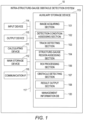
FIG. 1 schematically depicts a configuration example of an intra-structure-gauge obstacle detection system. -
FIG. 2 schematically depicts an example of an input image. -
FIG. 3 schematically depicts a configuration example of an ROI processing section. -
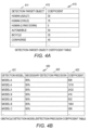
FIG. 4A schematically depicts a configuration example of a detection-target-object coefficient table. -
FIG. 4B schematically depicts a configuration example of an obstacle detection model/detection precision coefficient table. -
FIG. 4C schematically depicts a configuration example of a track width coefficient table. -
FIG. 4D schematically depicts a configuration example of a weather/time interval coefficient table. -
FIG. 5 depicts the procedure of a process example of the intra-structure-gauge obstacle detection system. -
FIG. 6 depicts the procedure of a process example of determination of ROIs. -
FIG. 7 depicts an example of a first pattern of the relation between a track and ROIs in an input image. -
FIG. 8 depicts an example of a second pattern of the relation between a track and ROIs in an input image. -
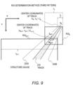
FIG. 9 depicts an example,of a third pattern of the relation between a track and ROIs in an input image. -
FIG. 10 depicts an example of a plurality of ROIs determined for an input image. - Hereinbelow, several embodiments are explained by use of the figures. Note that, in the following embodiments, explanation is given with regard to a plurality of divided sections or embodiments when it is necessary to do so for convenience; however, unless clearly noted otherwise particularly, they are mutually not unrelated, and one of them is related to a part or the whole of the others as a modification example, details, an additional explanation, or the like. The embodiments may be implemented separately, but may also be implemented in combination.
- In addition, in a case where numbers or the like related to an element (including a quantity, a numerical value, an amount, a range, and the like) are described in the following embodiments, the numbers are not limited to the particular numbers unless clearly noted otherwise particularly, except when the numbers are obviously limited to the particular numbers in principle, and so on, and the numbers may be equal to or greater than or equal to or smaller than the particular numbers.
- Further, it is not needless to say that constituent elements (including element steps and the like) of the following embodiments are not necessarily essential unless clearly noted otherwise particularly, except when those constituent elements are deemed to be obviously essential in principle, and so on.
- Similarly, when the shapes, positional relations, and the like of constituent elements and the like are described in the following embodiments, shapes, relations, and the like that are substantially approximate or similar to those shapes and the like are included, unless clearly noted otherwise particularly, except when they are deemed to be obviously not so in principle, and so on. The same applies also to numerical values and ranges.
- In addition, whereas explanation uses expressions like "xxx table" in some cases in the.following explanation, the information may be data with any structure. In addition, in the following explanation, the configuration of each table is an example. One table may be divided into two or more tables, and all or some of two or more tables may be one table. In addition, whereas functions are explained by use of the expression "xxx section" in some cases in the following explanation, the functions may also be realized by execution of one or more computer programs.
- An object detection system according to one embodiment of the present specification detects objects in an image captured from a moving body moving on a track with a specified width. For example, the system can be used for detection of obstacles of a railway vehicle travelling on a track including rails, a conveyance robot moving on a track which is a lane with a predetermined width, and the like. The system can be used for operation assistance, automated operation, and the like of moving bodies travelling on tracks. Hereinbelow, a specific explanation is given with regard to an example of a system that detects obstacles of a railway vehicle moving on rails.
- In automated operation or operation assistance of a railway vehicle, detection of obstacles in a structure gauge is required. An obstacle detection system explained in one embodiment of the present specification receives images captured with one camera that is attached to a railway vehicle and that monitors the front space, and detects obstacles in a structure gauge centered on a track.
- The structure gauge determines dimensional bounds defining a region around the track on which the railway vehicle is travelling and the construction of buildings, the planting of trees, or the like are prohibited in the region. The structure gauge is a region with a certain width L [m] centered on the center of the track on which the railway vehicle is moving. That is, both sides of the track are detection targets. The numerical value of the width L is predetermined for a certain track width R [m].
- In order to detect objects with smaller pixel counts in an input image, the obstacle detection system sets particular regions in an image as ROIs (Regions Of Interest), and treats only the ROIs as processing targets. It is supposed in an example explained below that an ROI is a square including two sides that are parallel to the vertical axis of an image and two sides parallel to the horizontal axis of the image. An ROI may have another shape, for example, an oblong.
- The region outside ROIs is excluded from processing targets. Accordingly, in performing obstacle detection using an input image captured with a front-space monitoring camera of the railway vehicle, the obstacle detection system sets ROIs on the basis of detection conditions required for detecting an obstacle appropriately. As a result, ROIs that enable appropriate balance of detection precision, a range of detection, a processing speed, and the like can be set.
- In the real world, the track width and the structure gauge width are constant widths. Here, in the present specification, v coordinates (ordinates) in the longitudinal direction and u coordinates (abscissas) in the lateral direction are set, with their origins at the upper left corner of an image. It can be considered that the ratios (scales) between lengths in the real world and lengths in the image do not change if v coordinates in the image of measured geographical points are the same.
- In view of this condition, the obstacle detection system according to one embodiment of the present invention determines ROIs on the basis of a track width in an image and a predetermined coefficient. This coefficient is called an ROI coefficient. Thus, it is possible to obtain ROIs that can satisfy necessary detection precision and have sizes sufficient for reducing computational costs.
- For example, the ROI coefficient is based on a pixel count of a target object in an image necessary for detection, the size of the detection-target object in the real world, the input image size of an object recognition program, and a track width in the real world. In one embodiment of the present specification, the width of an ROI is determined as the track width R [m] multiplied by the coefficient.
-
FIG. 1 is a block diagram schematically depicting a configuration example of an intra-structure-gauge obstacle detection system according to one embodiment of the present specification. An intra-structure-gaugeobstacle detection system 10 includes a calculatingdevice 111 having calculation capabilities and amain storage device 112 that provides a storage area that stores programs to be executed by the calculatingdevice 111 and processing-target data. For example, the calculatingdevice 111 is a CPU or a GPU including one or more cores, and, for example, themain storage device 112 is a DRAM including a volatile storage area. - The intra-structure-gauge
obstacle detection system 10 further includes a communication interface (IF) 116 that performs data communication with external devices such as another computer device, an external storage device, a camera, a microphone, or various types of sensors and anauxiliary storage device 113 that provides a non-volatile storage area using an HDD (Hard Disk Drive), a flash memory, or the like. - In addition, the intra-structure-gauge
obstacle detection system 10 includes aninput device 114 that accepts manipulation by a user and anoutput device 115 that presents output results of each process to the user. For example, theinput device 114 includes a keyboard and a mouse, and, for example, theoutput device 115 includes a display that displays results of detection by the intra-structure-gaugeobstacle detection system 10, a speaker that issues alerts, and the like. These constituent elements of the intra-structure-gaugeobstacle detection system 10 can communicate with each other via aninternal bus 117. - In
FIG. 1 , theauxiliary storage device 113 stores various types of programs that realize detection processes by the intra-structure-gaugeobstacle detection system 10, information to be referred to in the detection processes, and execution results of the processes. InFIG. 1 , theauxiliary storage device 113 has stored thereon various types of programs of animage acquiring section 101, a detectioncondition assessing section 102, atrack detecting section 103, a structure-gaugeregion assessing section 104, anROI processing section 106, anobstacle detecting section 107, and aresult output section 108. Further, theauxiliary storage device 113 has stored thereon a management information database (DB) 120 including,information necessary for obstacle detection. - The programs executed by the calculating
device 111 and processing-target data are loaded from theauxiliary storage device 113 onto themain storage device 112. In accordance with the respective programs described above, the calculatingdevice 111 can operate as functional sections corresponding to them. - The
image acquiring section 101 receives an image from a monitoring camera received via thecommunication interface 116. In one embodiment of the present specification, the input image is an image including an image of a track which is a captured image of the space in an advancing direction of a railway vehicle.FIG. 2 schematically depicts an example of the input image. Aninput image 20 includes atrack 25 extending forward from a railway vehicle. Thetrack 25 extends between trees around it. Thetrack 25 includes aleft rail 26 and aright rail 27, and these define the width of thetrack 25. v coordinates in the longitudinal direction and u coordinates in the lateral direction are set, with their origins at the upper left corner of theinput image 20. - Referring back to
FIG. 1 , the detectioncondition assessing section 102 assesses detection conditions for determining an ROI coefficient. The detection conditions are variables such as a target-object type (human, car, etc.), an input image, size (608 × 608, 416 × 416, etc.) of an object recognition program, necessary detection precision (whether it is necessary to perform detection with the precision of 99%, the precision of 90% is sufficient, etc.), weather, and daytime or nighttime. - Some or all of the detection conditions may be designated by a user via the
input device 114, and stored on themanagement information database 120 in advance. The detectioncondition assessing section 102 may assess at least some conditions by analyzing an input image or information from external sensors. - The
track detecting section 103 detects, from the input image, the track on which the railway vehicle is moving, and outputs coordinates of the track, for example, coordinates of the left and right rails and center coordinates of the track. The structure-gaugeregion assessing section 104 assesses a structure gauge in the input image on the basis of the coordinates of the track detected by thetrack detecting section 103, and outputs the structure gauge. The region inside the structure gauge is called a structure-gauge region. The structure-gauge region is a detection region where a target object should be detected, and are defined by two boundary lines representing the structure gauge on both sides. - On the basis of the detection conditions obtained by the assessment by the detection
condition assessing section 102, the track detection result obtained by the detection by thetrack detecting section 103, and the structure-gauge region obtained by the assessment by the structure-gaugeregion assessing section 104, theROI processing section 106 determines a plurality of ROIs, and outputs them. Theobstacle detecting section 107 performs an obstacle detection process by using, as input, an image included in each ROI. By using theoutput device 115, theresult output section 108 outputs obstacle detection results obtained by the detection by theobstacle detecting section 107. - The intra-structure-gauge
obstacle detection system 10 may be a physical computer system (one or more physical computers) or may be a system built on a group of computational resources (a plurality of computational resources) such as a cloud computing infrastructure. The intra-structure-gaugeobstacle detection system 10 may be mobile equipment such as a smartphone or a tablet. The computer system or the group of computational resources includes one or more interface devices, one or more storage devices (e.g., including a main storage device and an auxiliary storage device), and one or more calculating devices. - Since predetermined processes are performed by use of, for example, the storage devices and/or the interface devices as appropriate in a case where the functions are realized by execution of the programs by the calculating devices, the functions may be at least a part of the calculating devices. Processes explained by use of sentences whose subjects are the functions may be processes performed by the calculating devices or a system having their processors.
- The programs may be installed from a program source. For example, the program source may be a program distribution computer or a computer-readable storage medium (e.g., a computer-readable non-transitory storage medium). Each of the functions explained is an example. A plurality of functions may be integrated into one function, one function may be divided into a plurality of functions, and so on.
-
FIG. 3 is a block diagram schematically depicting the configuration of theROI processing section 106. Animage input section 301 receives, as input, the image captured by the monitoring camera and acquired by theimage acquiring section 101. A track detectionresult input section 302 receives, as input, the coordinates of the left and right rails of the track detected by thetrack detecting section 103. A detectioncondition input section 303 receives, as input, the detection conditions from the detectioncondition assessing section 102. - On the basis of the input detection conditions and information stored on the
management information database 120, an ROIcoefficient determining section 304 determines the ROI coefficient. A structure-gaugeregion input section 305 acquires the structure-gauge region in the image from the structure-gaugeregion assessing section 104. On the basis of the track detection result, the structure-gauge region, and the ROI coefficient, anROI determining section 306 determines a plurality of ROIs. AnROI output section 307 outputs the determined ROIs. - In one embodiment of the present specification, the ROI coefficient can be determined on the basis of the following perspective. Detection of a detection target requires a height p [pixel] in the image, and it is supposed here that statistically the average height of the detection target in the real world is P [m]. In addition, it is supposed here that the track width in the real world is R [m] and that the width of the track in the image at a certain geographical point is w [pixel]. Further, it is supposedhere that the length of one side of the size of an image to be input to an object detection model (program) is i [pixel]. Image data of the ROIs is enlarged or downsized, is standardized such that the length of each side of the images is i, and is input to the object detection model.
- The maximum ROI width with which the target object can be detected can be determined by the following formula, for example.

- The average height P of the detection-target object in the real world is determined depending on the detection-target object. In addition, the track width R is determined depending on the track on which the railway vehicle is travelling. The length i of one side of an image to be input to the object detection model is determined depending on the specifications of the object detection model.
- The height p required for object detection can be dependent on required detection precision of the object detection model or the clarity of input images. The clarity of input images can change depending on the surrounding environment, for example, weather or a time interval. Reducing the ROI widths means increasing the height of the detection-target object in images to be input to the object detection model.
- In one embodiment of the present specification, the detection conditions and coefficients for determining the ROI coefficient are retained in the
management information database 120 in order to determine the ROI coefficient. Hereinbelow, information that is included in themanagement information database 120 and is for associating the detection conditions and the ROI coefficient with each other is explained. -
FIG. 4A depicts a configuration example of a detection-target-object coefficient table 410. The detection-target-object coefficient table 410 associates detection-target objects and coefficients for calculating the ROI coefficient with each other. The detection-target-object coefficient table 410 includes a detection-target object field 411 and acoefficient field 412. A user can designate one or more detection-target objects in the detection-target objects depicted in the detection-target object field 411, via theinput device 114. In a case where a plurality of detection-target objects are designated, the smallest coefficient is selected for calculation of the ROI coefficient. -
FIG. 4B depicts a configuration example of an obstacle detection model/detection precision coefficient table 420. The obstacle detection model/detection precision coefficient table 420 manages the relation between necessary detection precision required for obstacle detection models (detection programs) and coefficients. The obstacle detection model/detection precision coefficient table 420 includes adetection model field 421, a necessarydetection precision field 422, and acoefficient field 423. - The
detection model field 421 represents the types of the obstacle detection models. The necessarydetection precision field 422 represents the lowest values of precision required for obstacle detection. Thecoefficient field 423 represents coefficients of combinations of the detection models and the necessary detection precision. The coefficients are used for the calculation of the ROI coefficient. In the present example, information regarding the size of an image to be input to an obstacle detection model, the information being necessary for the calculation of the ROI coefficient, is included in the coefficients in thecoefficient field 423. For example, in a case where the necessary precision is equal to or greater than 95%, the coefficient matches the size of an image to be input to a detection model. For example, an obstacle detection model and necessary detection precision are designated by a user via theinput device 114, and stored on themanagement information database 120. -
FIG. 4C depicts a configuration example of a track width coefficient table 430. The track width coefficient table 430 manages the relation between track widths and coefficients. The track width coefficient table 430 includes atrack width field 431 and acoefficient field 432. For example, a track width is designated by a user via theinput device 114, and stored on themanagement information database 120. -
FIG. 4D depicts a configuration example of a weather/time interval coefficient table 440. The weather/time interval coefficient table 440 manages the relation between weather/time intervals at the times of obstacle detection and coefficients. The weather/time interval coefficient table 440 includes aweather field 441, atime interval field 442, and acoefficient field 443. Theweather field 441 represents weather such as fine weather or rain, and thetime interval field 442 represents time intervals such as daytime or nighttime. Note that the weather field or the time interval field may represent weather or time intervals by another method. Thecoefficient field 423 represents coefficients for combinations of weather and time intervals. - For example, a weather/time interval may be designated by a user via the
input device 114 before the start of operation, and stored on themanagement information database 120. The detectioncondition assessing section 102 may determine a weather/time interval on the basis of information from sensors or an external system. For example, the detectioncondition assessing section 102 can assess weather by using an external weather information system or a meteorological sensor. The detectioncondition assessing section 102 can assess the time interval by using a timer or an illuminance sensor. - As described above, in one embodiment of the present specification, the detection conditions can include a detection-target object, necessary detection precision, a track width, weather, and a time interval, in the real world, and the like. The ROI
coefficient determining section 304 acquires coefficients from the tables 410, 420, 430, and 440 by using the detection conditions (a detection-target object, a detection model, necessary detection precision, a track width, weather, a time interval) as keys. The ROIcoefficient determining section 304 calculates the ROI coefficient by integrating all the acquired coefficients and a constant independent of the detection conditions. - Note that some conditions of the conditions depicted in
FIGS. 4A to 4D may be omitted, or other conditions may be added. For example, the obstacle detection model/detection precision coefficient table 420 and the weather/time interval coefficient table 440 may be omitted. - Next, an operation of the intra-structure-gauge
obstacle detection system 10 is explained.FIG. 5 depicts a flowchart of the operation of the intra-structure-gaugeobstacle detection system 10. Instep 501, theimage acquiring section 101 receives an input image from an external camera. - In
step 502, thetrack detecting section 103 detects a track in the input image. The detection of a track may be performed by image processing, or coordinates of a track in the input image may be calculated by using a GPS or map data. Since the track extends from the front end of the railway vehicle, it can be detected easily as compared with obstacles or the like. For example, coordinates of the track represent the centerline between the left and right rails. As described above, v coordinates in the longitudinal direction and u coordinates in the lateral direction are set, with their origins at the upper left corner of the input image. Coordinates of the track represent the u coordinate and v coordinate of each point of the centerline. For example, the values of the v coordinates increase from the upper side to the lower side of the image, and the values of the u coordinate increase from the left side to the right side of the image. - Further, the structure-gauge
region assessing section 104 determines a structure gauge. The structure gauge includes two structure-gauge lines, and a region outlined by the structure-gauge lines is a structure-gauge region. The structure-gauge region is a region having its center at the u coordinates of the track, and its width which is the track width multiplied by a constant. In a case where it is supposed that the width of the structure gauge in the real world is L [m] and the width of the track in the real world is R' [m], the constant is L/R. The value of L is preset, and, for example, is stored on themanagement information database 120. - Next, in
step 503, the detectioncondition assessing section 102 assesses detection conditions by the method described before. In the example described above, the detectioncondition assessing section 102 determines a detection-target object, an object detection model, necessary detection precision, a track width, weather, and a time interval. - In
step 505, theROI processing section 106 determines a necessary and sufficient number of ROIs with necessary and sufficient sizes, on the basis of detection results of the track and the structure-gauge region instep 502 and the detection conditions assessed instep 503. Details of the process of theROI processing section 106 instep 505 are described later. - In
step 506, theobstacle detecting section 107 performs an obstacle detection process on all the ROIs. In a case where an obstacle is detected (507: YES), the procedure proceeds to step 508. Instep 508, theresult output section 108 issues an obstacle detection alert. In a case where theresult output section 108 can manipulate a human interface for a motorman, theresult output section 108 may give a warning to the motorman, or in a case where theresult output section 108 is connected with an operation control device of the railway vehicle, theresult output section 108 may perform a process of decelerating the vehicle. - After
step 508, the procedure proceeds to step 509. In a case where obstacles are not detected in step 506 (507: NO), the procedure proceeds to step 509. Instep 509, theimage acquiring section 101 assesses whether there is an input image that should be processed next. In a case where there is an input image that should be processed next (509: YES), the procedure returns to step 501, and the next input image is received. In a case where there is not an input image that should be processed next (509: NO), the present process ends. - Hereinbelow, detail of the process of the
ROI processing section 106 performed instep 505 are explained.FIG. 6 depicts a flowchart of the process performed by theROI processing section 106 instep 505. Instep 601, theimage input section 301 receives an input image. For example, the input image is an image as the one depicted inFIG. 2 . - In
step 602, the track detectionresult input section 302 receives a track detection result from thetrack detecting section 103. Further, the structure-gaugeregion input section 305 receives information regarding the structure-gauge region from the structure-gaugeregion assessing section 104. Instep 603, the detectioncondition input section 303 receives the detection conditions from the detectioncondition assessing section 102. - In
step 604, the ROIcoefficient determining section 304 determines an ROI coefficient. Specifically, in accordance with the detection conditions acquired from the detectioncondition input section 303, the ROIcoefficient determining section 304 acquires coefficients from the detection-target-object coefficient table 410, the obstacle detection model/detection precision coefficient table 420, the track width coefficient table 430, and the weather/time interval coefficient table 440. The ROIcoefficient determining section 304 calculates, as the ROI coefficient, the product of the acquired coefficients and the predetermined constant. - In
step 605, theROI determining section 306 determines a v coordinate v1 of a detection starting geographical point in the input image. v1 is the v coordinate of a geographical point which is the farthest from the vehicle in monitoring-target geographical points. That is, v1 is the top monitoring-target geographical point in the image, and is the minimum value in v coordinates of the monitoring-target geographical points. In an example of a method of determining v1, a geographical point which is the farthest from the vehicle in coordinates of a detected track (coordinates of the centerline of the track) is set as v1. In another example, v1 may be determined on the basis of a braking distance calculated from the travelling speed of the railway vehicle. Here, 1 is assigned to a variable k. - In
step 606, theROI determining section 306 determines a width rk of an ROIk which is the k-th ROI, by multiplying a width wk of the track at a geographical point at a v coordinate vk in a screen by the ROI coefficient. As described above, it is supposed here that the ROI is a square. The v coordinate of the upper side of the ROIk is vk. vk is the reference ordinate value of the ROIk. - Next, in
step 607, theROI determining section 306 searches for a geographical point (position) where the ROIk starts being unable to cover the structure-gauge region, that is, a geographical point where the structure-gauge region goes out of the ROIk first. The v coordinate of the geographical point is set as vk+1. - There are three patterns of modes where the ROIk starts being unable to cover the structure-gauge region.
- In addition, as a fourth pattern, there is a case where there is not such a geographical point, that is, a case where the ROIk covers the closest end of the structure-gauge region in the image. The
ROI determining section 306 assesses which of the four patterns described above is true of the ROIk, on the basis of the relation between the ROIk and the track in the image. - The geographical point where the structure-gauge region goes out of the ROIk. depends on the shape and position of the ROIk. As described above, the length rk of one side of the ROIk and the v coordinate vk of the upper side of the ROIk have been determined already, and the u coordinate of the ROIk has not been determined. The final u coordinate of the ROIk is determined in
step 608 described later. TheROI determining section 306 adjusts the u coordinate of the ROIk, and assesses which of the patterns described above the ROIk corresponds to. -
FIG. 7 schematically depicts a first pattern of the ROIk starting being unable to cover the structure-gauge region. In the first pattern, both two structure-gauge lines cross the upper side and the lower side of the ROIk. - In an input image depicted in
FIG. 7 , atrack 210 extends forward from the near side. That is, thetrack 210 extends from the lower side to the upper side of the input image. InFIG. 7 , u coordinates increase from the left side to the right side, and v coordinates increase from the upper side to the lower side. -
FIG. 7 depicts two consecutive ROIs, and depicts the preceding ROIk and the following ROIk+1. In the first pattern, each of two structure-gauge lines track 210 crosses the upper side and the lower side of the ROIk. The center Ck of thetrack 210 on the upper side of the ROIk has coordinates (uk,vk). - On the upper side of the ROIk, that is, at the v coordinate vk, the
track 210 has, the width wk, and the structure-gauge region has a width lk. The ROIk has the width rk. The widths of thetrack 210 and the structure-gauge region are lengths along the u axis. As described above, the relation of lk = (L/R)wk holds true. - Two lower intersections of the structure-
gauge lines - That is, the v coordinate vk+1 of the upper side of the following ROIk+1 coincides with the v coordinate (vk+rk) of the lower side of the ROIk. An intersection Ck+1 of the upper side of the ROIk+1 and the centerline of the
track 210 has coordinates (uk+1, vk+1). - On the upper side of the ROIk+1, that is, at the v coordinate vk+1, the
track 210 has a width wk+1, and the structure-gauge region has a width lk+1. The ROIk+1 has a width rk+1. The relation of lk+1 = (L/R)wk+1 holds true. - In the first pattern, there are abscissa values of the ROIk at which both the lower intersections of the two structure-gauge lines and the ROIk are positioned on the lower side of the ROIk. The abscissa values can be set as abscissa values of the ROIk for performing the target-object detection process.
-
FIG. 8 schematically depicts a second pattern of the ROIk starting being unable to cover the structure-gauge region. In the second pattern, the left structure-gauge line crosses the upper side and the left side of the ROIk. The right structure-gauge line crosses the upper side and the right side of the ROIx. - In the example in
FIG. 8 , a left structure-gauge line 220A of thetrack 210 crosses the upper side and the left side of the ROIk. A right structure-gauge line 220B of thetrack 210 crosses the upper side and the right side of the ROIk. - The center Ck of the
track 210 on the upper side of the ROIk has the coordinates. (uk, vk). On the upper side of the ROIk, that is, at the v coordinate vk, thetrack 210 has the width wk, and the structure-gauge region has the width lk. The ROIk has the width rk. The widths of thetrack 210 and the structure-gauge region are lengths along the u axis. The relation of lk = (L/R)wk holds true. - The lower intersection of the structure-
gauge line 220A and the ROIk is positioned on the left side of the ROIk, and the lower intersection of the structure-gauge line 220B and the ROIk is positioned on the right side of the ROIk. In the example inFIG. 8 , the v coordinates of the lower intersections are the same. Accordingly, the v coordinate of the geographical point where the ROIk starts being unable to cover the structure-gauge region is the v coordinate of the lower intersections of the structure-gauge lines - The v coordinate of the geographical point where the ROIk starts being unable to cover the structure-gauge region is the v coordinate vk+1 of the upper side of the following ROIk+1. That is, the v coordinate vk+1 of the upper side of the following ROIk+1 coincides with the v coordinates of the lower intersections. The intersection Ck+1 of the upper side of the ROIk+1 and the centerline of the
track 210 has the coordinates (uk+1, vk+1). - On the upper side of the ROIk+1, that is, at the v coordinate Vk+1, the
track 210 has the width wk+1, and the structure-gauge region has the width lk+1. The ROIk+1. has the width rk+1. The relation of lk+1 = (L/R)wk+1 holds true. The width lk+1 of the structure-gauge region is the same as the width rk+1 of the ROIk+1. That is, a position where the width lk+1 of the structure-gauge region and the width rk+1 of the ROIk+1 become the same is the position of the geographical point where the ROIk starts being unable to cover the structure-gauge region. - In the second pattern, there are abscissa values of the ROIk at which the lower intersections of the two structure-gauge lines and the ROIk are positioned on the left side and the right side of the ROIk, respectively. Abscissa values of the ROIk for performing the target-object detection process can be determined such that the ordinate positions of the lower intersections are the same.
-
FIG. 9 schematically depicts a third pattern of the ROIk starting being unable to cover the structure-gauge region. In the third pattern, one of the left structure-gauge line and the right structure-gauge line crosses the upper side and the left side or the right side of the ROIk. The other of the left structure-gauge line and the right structure-gauge line crosses the upper side and the lower side of the ROIk. - In the example in
FIG. 9 , thetrack 210 curves significantly. The left structure-gauge line 220A of thetrack 210 crosses the upper side and the left side of the ROIk. The right structure-gauge line 220B of thetrack 210 crosses the upper side and the lower side of the ROIk. - The center Ck of the
track 210 on the upper side of the ROIk has the coordinates (uk, vk). On the upper side of the ROIk, that is, at the v coordinate vk, thetrack 210 has the width wk, and the structure-gauge region has the width lk. The ROIk has the width rk. The widths of thetrack 210 and the structure-gauge region are lengths along the u axis. The relation of lk = (L/R)wk holds true. - The lower intersection of the structure-
gauge line 220A and the ROIk is positioned on the left side of the ROIk, and the lower intersection of the structure-gauge line 220B and the ROIk is positioned on the lower side of the ROIk. The position of an intersection positioned higher, that is, positioned farther, among the lower intersections of the two structure-gauge lines is the position of the geographical point where the ROIk starts being unable to cover the structure-gauge region. - The v coordinate of the geographical point where the ROIk starts being unable to cover the structure-gauge region is the v coordinate vk+1 of the upper side of the following ROIk+1. That is, the v coordinate vk+1 of the upper side of the following ROIk+1 is the v coordinate of the intersection positioned higher, that is, positioned farther, among the lower intersections of the two structure-gauge, lines. The same applies to the first and second patterns.
- The intersection Ck+1 of the upper side of the ROIk+1 and the centerline of the
track 210 has the coordinates (uk+1, vk+1). On the upper side of the ROIk+1, that is, at the v coordinate vk+1, thetrack 210 has the width wk+1, and the structure-gauge region has the width lk+1. The ROIk+1 has the width rk+1. The relation of lk+1 = (L/R)wk+1 holds true. - As described above, in the third pattern, the u coordinate of the centerline of the
track 210 changes significantly. The position where the ROIk starts being unable to cover the structure-gauge region is a geographical point where the width rk of the ROIk becomes insufficient for the width of the structure-gauge region, that is, a geographical point where (|uk+1-uk| + (lk+lk+1)/2) = rk. - In the third pattern, there are abscissa values of the ROIk at which the lower intersection of one of the two structure-gauge lines: and the ROIk is positioned on the right side or the left side of the ROIk and the lower intersection of the other of the two structure-gauge lines and the ROIk is positioned on the lower side of the ROIk. Abscissa values of the ROIk for performing the target-object detection process can be determined such that, on a side opposite to the lower intersection of the one of the two structure-gauge lines and the ROIk, the upper intersection of the one of the two structure-gauge lines and the ROIk coincides with the upper corner of the ROIk.
- As explained with reference to
FIGS. 7 to 9 , the structure-gauge region is defined by the two structure-gauge lines ROI determining section 306 selects an intersection which is closer, that is, which has a greater v coordinate, among two intersections of each structure-gauge line and the ROIk. Further, theROI determining section 306 determines a farther intersection among the selected intersections of the two structure-gauge lines as a geographical point where the ROIk starts being unable to cover the structure-gauge region. That is, abscissa values of an ROI are determined such that the top position in the two lower intersections of the two structure-gauge lines and the ROI coincides with the lowest position of the image. - The fourth pattern is a case where the ROIk reaches the lower end of the screen, and an ROI1 to the ROIk cover the entire structure-gauge region in the input image.
- In the examples described above, the v coordinate vk where the width of the track is measured is used as the v coordinate value of the upper end of the ROIk. The v coordinate vk is the reference ordinate value of the ROIk. In another example, the v coordinate value of the upper end of the ROIk may be different from vk, for example, may be positioned higher than vk.
- Referring back to
FIG. 6 , as described above, instep 607, theROI determining section 306 identifies a geographical point where the ROIk starts being unable to cover the structure-gauge region, and assesses a relevant pattern. Next, instep 608, theROI determining section 306 determines the center u coordinate of the ROIk. In accordance with the pattern of the ROIk starting being unable to cover the structure-gauge region, theROI determining section 306 can determine the center u coordinate of the ROIk. - In the case of the first pattern, the
ROI determining section 306 determines, as the u coordinate of the center of the ROIk, the average of the u coordinate of the center of the track on the upper side (v coordinate vk) of the ROIk and the u coordinate of the center of the track on the lower side (v coordinate vk+1). As a result, the ROIk can surely include the entire region of the structure-gauge region from the v coordinate vk to the v coordinate vk+1. The ROIk inFIG. 7 satisfies this condition. - In the case of the second pattern, the u coordinate of the center of the ROIk is determined such that the v coordinates of the intersections of the two structure-gauge lines and the left and right sides of the ROIk become the same. The u coordinate of the center of the ROIk and the u coordinate of the center of the track at the v coordinate vk+1 match. As a result, the ROIk can include the entire region of the structure-gauge region from the v coordinate vk to the v coordinate vk+1. The ROIk in
FIG. 8 satisfies this condition. - In the case of the third pattern, the
ROI determining section 306 may determine, as the u coordinate of the center of the ROIk, (uk+lk/2-rk/2 (when uk > uk+1)) or (uk-lk/2+rk/2 (when uk < uk+1)). As a result, the ROIk can include the entire region of the structure-gauge region from the v coordinate vk to the v coordinate vk+1. One of the structure-gauge lines crosses the upper corner of the ROIk. The ROIk inFIG. 9 satisfies this condition. - In the case of the fourth pattern, the
ROI determining section 306 determines, as the u coordinate of the center of the ROIk, the u coordinate of the center of the track at the v coordinate vk. As a result, the ROIk can include the entire region of the structure-gauge region in the image. - Note that the u coordinate value of the ROIk in each pattern may be determined by a method that is different from the methods described above. For example, in all the patterns, the u coordinate of the center of the track at the v coordinate vk may be determined as the u coordinate of the center of the ROIk.
- Next, in
step 610, theROI determining section 306 assesses whether a geographical point (v coordinate vk+1) where the ROIk starts being unable to cover the structure-gauge region has been detected. In a case where there are no geographical points where the ROIk starts being unable to cover the structure-gauge region, that is, in the case of the fourth pattern (610: NO), the procedure proceeds to step 612. TheROI output section 307 outputs all ROIs. As a result, the ROI determination process instep 505 inFIG. 5 is completed. - In a case where a geographical point where the ROIk starts being unable to cover the structure-gauge region is detected, that is, in the case of the first, second, or third pattern (610: YES), in
step 611, theROI determining section 306 increments k. Thereafter, the procedure returns to step 606, and the next ROI is determined at a new position of the v coordinate vk. - By the procedure described above, one or more ROIs cover the structure-gauge region in an input image over the range from the far side to the near side. In a case where a plurality of ROIs are defined for one input image, target objects can be detected in each ROI with the necessary detection precision set in the detection conditions.
-
FIG. 10 depicts an example of a plurality of ROIs formed for one input image. InFIG. 10 , three ROIs are formed for theinput image 20, and the three ROIs covers the entire structure-gauge region in theinput image 20. The three ROIs are the ROI1, the ROI2, and the ROI3. The ROI1 and the ROI2 are ROIs of the second pattern explained with reference toFIG. 8 , and the ROI3 is an ROI of the fourth pattern. Each ROI represents a detection limit of a region within which target objects can be detected. - As described above, the
ROI determining section 306 determines the v coordinate v1 of the ROI1, which is the first ROI, and the ROI coefficient. From the ROI coefficient and the track width at the v coordinate v1, the length of one side of the ROI1 is determined. On the upper side of the ROI1, that is, at the v coordinate v1, thetrack 210 has a width w1, and the structure-gauge region has a width l1. The ROI1 has a width r1. - The
ROI determining section 306 adjusts the u coordinate of the ROI1 as necessary, and assesses the relation between the ROI1 and the structure gauge. The relation between the ROI1 and thetrack 210 corresponds to the second pattern. InFIG. 10 , the left structure-gauge line 220A of thetrack 210 crosses the upper side and the left side of the ROI1. The right structure-gauge line 220B of thetrack 210 crosses the upper side and the right side of the ROI1. - The u coordinate of the center of the ROI1 is determined such that the intersection of the structure-
gauge line 220A and the ROI1 and the lower intersection of the structure-gauge line 220B and the ROI1 have the same v coordinate. The v coordinate of the geographical point where the ROI1 starts being unable to cover the structure-gauge region is a v coordinate v2 of the lower intersections of the structure-gauge lines - The
ROI determining section 306 performs a process of forming the next ROI2 at the v coordinate v2. The formation of the ROI2 is similar to the formation of the ROI1 described above. On the upper side of the ROI2, that is, at the v coordinate v2, thetrack 210 has a width w2, and the structure-gauge region has a width l2. The ROI2 has a width r2. The structure-gauge lines - Last, the ROI3 is formed at the v coordinate v3. At the v coordinate v3, the
track 210 has a width w3, and the structure-gauge region has a width l3. The ROI3 has a width r3. The relation between the ROI3 and the structure-gauge region corresponds to the fourth pattern. The u coordinate of the center of the ROI3 is determined in such a manner as to coincide with the u coordinate of the center of thetrack 210 at the v coordinate v3. - Note that the present invention is not limited to the embodiments described above, and includes various modification examples. For example, the embodiments described above are explained in detail for explaining the present invention in an easy-to-understand manner, and the present invention is not necessarily limited to those including all constituent elements explained.. In addition, it is possible to replace some of the constituent elements of an embodiment with constituent elements of another embodiment, and it is also possible to add constituent elements of an embodiment to the constituent elements of another embodiment. In addition, some of constituent elements of each embodiment can also have other constituent elements additionally, be removed, or be replaced.
- In addition, each constituent element, function, processing section, or the like described above may.be partially or entirely realized by hardware by, for example, designing it with an integrated circuit. In addition, each constituent element, function, and the like described above may be realized by software by a processor interpreting and executing a program to realize each function. Information such as a program, a table or a file to realize each function can be placed on a recording device such as a memory, a hard disk, or an SSD (Solid State Drive) or a recording medium such as an IC card or an SD card.
- In addition, depicted control lines and information lines are ones that are considered to be necessary for explanation, and all control lines and information lines that are necessary for products are not necessarily depicted. It may be considered that, in practice, almost all constituent elements are interconnected.
Claims (11)
- A system that detects a target object in an image, the system comprising:one or more storage devices; andone or more calculating devices, whereinthe one or more storage devices store a coefficient, andthe one or more calculating devicesacquire an image captured from a moving body moving on a track,detect the track in the image,determine a width of the track at a reference ordinate value selected on the image,determine a size of a region of interest in the image on a basis of the width of the track and the coefficient,determine a positional coordinate of the region of interest in the image on a basis of the reference ordinate value and the detected track, andexecute a target-object detection process on the region of interest at the determined positional coordinate.
- The system according to claim 1, wherein
the one or more calculating devicesdetermine an ordinate value of the region of interest on a basis of the reference ordinate value,determine a detection region where a target object should be detected, on a basis of the detected track, anddetermine abscissa values of the region of interest on a basis of a positional relation between the detection region and the region of interest. - The system according to claim 2, whereinthe detection region is defined by two boundary lines extending in an up-down direction in the image, andthe one or more calculating devices determine the abscissa values of the region of interest such that a top position of two lower intersections of the two boundary lines and the region of interest is at a lowest position of the image.
- The system according to claim 2, whereinthe detection region is defined by two boundary lines extending in an up-down direction in the image,the region of interest is a rectangle including two sides parallel to an axis of an abscissa and two sides parallel to an axis of an ordinate, and,in a case where there are abscissa values of the region of interest at which both lower intersections of the two boundary lines and the region of interest are positioned on a lower side of the region of interest, the one or more calculating devices determine the abscissa values as abscissa values of the region of interest for performing the target-object detection process.
- The system according to claim 2, whereinthe detection region is defined by two boundary lines extending in an up-down direction in the image,the region of interest includes two sides parallel to an axis of an abscissa and two sides parallel to an axis of an ordinate, andthe one or more calculating devices, in a case where there are abscissa values of the region of interest at which lower intersections of the two boundary lines and the region of interest are positioned on a left side and a right side of the region of interest, respectively, determine abscissa values of the region of interest for performing the target-object detection process such that ordinate positions of the lower intersections are the same.
- The system according to claim 2, whereinthe detection region is defined by two boundary lines extending in an up-down direction in the image,the region of interest includes two sides parallel to an axis of an abscissa and two sides parallel to an axis of an ordinate, andthe one or more calculating devices, in a case where there are abscissa values of the region of interest at which a lower intersection of one of the two boundary lines and the region of interest is positioned on a right side or a left side of the region of interest and a lower intersection of the other of the two boundary lines and the region of interest is positioned on a lower side of the region of interest, determine abscissa values of the region of interest for performing the target-object detection process such that, on a side opposite to the lower intersection of the one of the two boundary lines and the region of interest, an upper intersection of the one of the two boundary lines and the region of interest coincides with an upper corner of the region of interest.
- The system according to claim 1, wherein a width of the region of interest is the width of the track multiplied by a constant.
- The system according to claim 1, whereinthe one or more calculating devices determine the coefficient on a basis of a user-designated detection condition, and stores the coefficient on the one or more storage devices, andthe detection condition includes at least one of a target-object type, detection precision, a track width, and a surrounding environment.
- The system according to claim 2, whereinthe detection region is defined by two boundary lines extending in an up-down direction in the image, andthe one or more calculating devices select the reference ordinate value for a next region of interest on a basis of a top position of two lower intersections of the two boundary lines and the region of interest on which the target-object detection process has been executed.
- The system according to claim 9, whereinthe region of interest includes two sides parallel to an axis of an abscissa and two sides parallel to an axis of an ordinate,an ordinate value of the top position of the two lower intersections of the two boundary lines and the region of interest on which the target-object detection process has been executed is the reference ordinate value for the next region of interest, andthe reference ordinate value' selected on the image is an ordinate value of an upper side of the next region of interest.
- A method of detecting a target object in an image, the method comprising:acquiring an image captured from a moving body moving on a track;detecting the track in the image;determining a width of the track at a reference ordinate value selected on the image;determining a size of a region of interest in the image on a basis of the width of the track and a designated coefficient;determining a positional coordinate of the region of interest in the image on a basis of the reference ordinate value and the detected track; andexecuting a target-object detection process on the region of interest at the determined positional coordinate.
Applications Claiming Priority (2)
| Application Number | Priority Date | Filing Date | Title |
|---|---|---|---|
| JP2021141404A JP7734534B2 (en) | 2021-08-31 | 2021-08-31 | System for detecting an object and method for detecting an object |
| PCT/JP2022/017760 WO2023032344A1 (en) | 2021-08-31 | 2022-04-14 | System for detecting object and method for detecting object |
Publications (2)
| Publication Number | Publication Date |
|---|---|
| EP4397564A1 true EP4397564A1 (en) | 2024-07-10 |
| EP4397564A4 EP4397564A4 (en) | 2025-07-02 |
Family
ID=85412071
Family Applications (1)
| Application Number | Title | Priority Date | Filing Date |
|---|---|---|---|
| EP22863934.0A Pending EP4397564A4 (en) | 2021-08-31 | 2022-04-14 | SYSTEM FOR OBJECT RECOGNITION AND METHOD FOR OBJECT RECOGNITION |
Country Status (3)
| Country | Link |
|---|---|
| EP (1) | EP4397564A4 (en) |
| JP (1) | JP7734534B2 (en) |
| WO (1) | WO2023032344A1 (en) |
Families Citing this family (2)
| Publication number | Priority date | Publication date | Assignee | Title |
|---|---|---|---|---|
| JP2026002633A (en) * | 2024-06-21 | 2026-01-08 | 株式会社日立製作所 | Obstacle Detection System |
| KR102842712B1 (en) * | 2024-11-08 | 2025-08-06 | 한국철도기술연구원 | Real-time railway track detection method based on images |
Family Cites Families (7)
| Publication number | Priority date | Publication date | Assignee | Title |
|---|---|---|---|---|
| JP6381981B2 (en) * | 2014-06-12 | 2018-08-29 | 西日本旅客鉄道株式会社 | Track space obstacle detection system |
| US11021177B2 (en) * | 2016-10-20 | 2021-06-01 | Rail Vision Ltd | System and method for object and obstacle detection and classification in collision avoidance of railway applications |
| JP7000232B2 (en) | 2018-04-02 | 2022-02-04 | 株式会社東芝 | Forward monitoring device, obstacle collision avoidance device and train control device |
| EP3787953B1 (en) * | 2018-05-01 | 2025-07-30 | Rail Vision Ltd | System and method for dynamic selection of high sampling rate for a selected region of interest |
| JP7217094B2 (en) * | 2018-05-30 | 2023-02-02 | 日本信号株式会社 | monitoring device |
| JP7316107B2 (en) * | 2019-06-19 | 2023-07-27 | 日本信号株式会社 | monitoring device |
| JP6714942B1 (en) | 2020-03-04 | 2020-07-01 | フォクレット合同会社 | Communication system, computer program, and information processing method |
-
2021
- 2021-08-31 JP JP2021141404A patent/JP7734534B2/en active Active
-
2022
- 2022-04-14 EP EP22863934.0A patent/EP4397564A4/en active Pending
- 2022-04-14 WO PCT/JP2022/017760 patent/WO2023032344A1/en not_active Ceased
Also Published As
| Publication number | Publication date |
|---|---|
| JP2023034917A (en) | 2023-03-13 |
| EP4397564A4 (en) | 2025-07-02 |
| WO2023032344A1 (en) | 2023-03-09 |
| JP7734534B2 (en) | 2025-09-05 |
Similar Documents
| Publication | Publication Date | Title |
|---|---|---|
| CN109087510B (en) | Traffic monitoring method and device | |
| EP3063552B1 (en) | Method and apparatus for road width estimation | |
| JP4409035B2 (en) | Image processing apparatus, singular part detection method, and recording medium recording singular part detection program | |
| CN110286389B (en) | Grid management method for obstacle identification | |
| JP6850324B2 (en) | Obstacle distribution simulation method, device, terminal and program based on multi-model | |
| CN109871787B (en) | Obstacle detection method and device | |
| CN111295321A (en) | Obstacle detection device | |
| EP4397564A1 (en) | System for detecting object and method for detecting object | |
| CN110349260B (en) | Automatic pavement marking extraction method and device | |
| CN113424240B (en) | Driving road identification device | |
| CN102208013A (en) | Scene matching reference data generation system and position measurement system | |
| DE102011117585A1 (en) | Systems and methods for tracking objects | |
| US10748014B2 (en) | Processing device, object recognition apparatus, device control system, processing method, and computer-readable recording medium | |
| CN112912894B (en) | Road boundary identification method and device | |
| CN112818792A (en) | Lane line detection method, lane line detection device, electronic device, and computer storage medium | |
| US12243321B2 (en) | Method for determining a semantic free space | |
| DE112018004835T5 (en) | Collision prediction device, collision prediction method and program | |
| WO2021000787A1 (en) | Method and device for road geometry recognition | |
| CN113536867B (en) | Methods, devices and systems for object recognition | |
| CN114387293A (en) | Road edge detection method and device, electronic equipment and vehicle | |
| CN119291717A (en) | Railway track obstacle detection method and system | |
| CN114998855A (en) | Road edge line generation method and device, storage medium and computer equipment | |
| CN111583257B (en) | Method, device and system for detecting foreign body intrusion in railway boundary | |
| KR20200058272A (en) | Method and system for providing road driving situation through preprocessing of road driving image | |
| CN112561967A (en) | Control method and device for vehicle door lock |
Legal Events
| Date | Code | Title | Description |
|---|---|---|---|
| STAA | Information on the status of an ep patent application or granted ep patent |
Free format text: STATUS: THE INTERNATIONAL PUBLICATION HAS BEEN MADE |
|
| PUAI | Public reference made under article 153(3) epc to a published international application that has entered the european phase |
Free format text: ORIGINAL CODE: 0009012 |
|
| STAA | Information on the status of an ep patent application or granted ep patent |
Free format text: STATUS: REQUEST FOR EXAMINATION WAS MADE |
|
| 17P | Request for examination filed |
Effective date: 20240331 |
|
| AK | Designated contracting states |
Kind code of ref document: A1 Designated state(s): AL AT BE BG CH CY CZ DE DK EE ES FI FR GB GR HR HU IE IS IT LI LT LU LV MC MK MT NL NO PL PT RO RS SE SI SK SM TR |
|
| DAV | Request for validation of the european patent (deleted) | ||
| DAX | Request for extension of the european patent (deleted) | ||
| A4 | Supplementary search report drawn up and despatched |
Effective date: 20250602 |
|
| RIC1 | Information provided on ipc code assigned before grant |
Ipc: G06T 7/60 20170101ALI20250526BHEP Ipc: G06T 7/00 20170101ALI20250526BHEP Ipc: B61L 23/00 20060101AFI20250526BHEP |
|
| GRAP | Despatch of communication of intention to grant a patent |
Free format text: ORIGINAL CODE: EPIDOSNIGR1 |
|
| STAA | Information on the status of an ep patent application or granted ep patent |
Free format text: STATUS: GRANT OF PATENT IS INTENDED |
|
| INTG | Intention to grant announced |
Effective date: 20251121 |
|
| GRAS | Grant fee paid |
Free format text: ORIGINAL CODE: EPIDOSNIGR3 |