EP4397563A1 - Autonomous transport vehicle and towing and transportation method - Google Patents
Autonomous transport vehicle and towing and transportation method Download PDFInfo
- Publication number
- EP4397563A1 EP4397563A1 EP21956013.3A EP21956013A EP4397563A1 EP 4397563 A1 EP4397563 A1 EP 4397563A1 EP 21956013 A EP21956013 A EP 21956013A EP 4397563 A1 EP4397563 A1 EP 4397563A1
- Authority
- EP
- European Patent Office
- Prior art keywords
- transported object
- weight
- autonomous transport
- transport vehicle
- vehicle body
- Prior art date
- Legal status (The legal status is an assumption and is not a legal conclusion. Google has not performed a legal analysis and makes no representation as to the accuracy of the status listed.)
- Granted
Links
Images



Classifications
-
- B—PERFORMING OPERATIONS; TRANSPORTING
- B66—HOISTING; LIFTING; HAULING
- B66F—HOISTING, LIFTING, HAULING OR PUSHING, NOT OTHERWISE PROVIDED FOR, e.g. DEVICES WHICH APPLY A LIFTING OR PUSHING FORCE DIRECTLY TO THE SURFACE OF A LOAD
- B66F9/00—Devices for lifting or lowering bulky or heavy goods for loading or unloading purposes
- B66F9/06—Devices for lifting or lowering bulky or heavy goods for loading or unloading purposes movable, with their loads, on wheels or the like, e.g. fork-lift trucks
-
- B—PERFORMING OPERATIONS; TRANSPORTING
- B62—LAND VEHICLES FOR TRAVELLING OTHERWISE THAN ON RAILS
- B62D—MOTOR VEHICLES; TRAILERS
- B62D63/00—Motor vehicles or trailers not otherwise provided for
- B62D63/02—Motor vehicles
-
- B—PERFORMING OPERATIONS; TRANSPORTING
- B60—VEHICLES IN GENERAL
- B60P—VEHICLES ADAPTED FOR LOAD TRANSPORTATION OR TO TRANSPORT, TO CARRY, OR TO COMPRISE SPECIAL LOADS OR OBJECTS
- B60P1/00—Vehicles predominantly for transporting loads and modified to facilitate loading, consolidating the load, or unloading
- B60P1/02—Vehicles predominantly for transporting loads and modified to facilitate loading, consolidating the load, or unloading with parallel up-and-down movement of load supporting or containing element
-
- B—PERFORMING OPERATIONS; TRANSPORTING
- B60—VEHICLES IN GENERAL
- B60P—VEHICLES ADAPTED FOR LOAD TRANSPORTATION OR TO TRANSPORT, TO CARRY, OR TO COMPRISE SPECIAL LOADS OR OBJECTS
- B60P1/00—Vehicles predominantly for transporting loads and modified to facilitate loading, consolidating the load, or unloading
- B60P1/64—Vehicles predominantly for transporting loads and modified to facilitate loading, consolidating the load, or unloading the load supporting or containing element being readily removable
- B60P1/6409—Vehicles predominantly for transporting loads and modified to facilitate loading, consolidating the load, or unloading the load supporting or containing element being readily removable details, accessories, auxiliary devices
-
- B—PERFORMING OPERATIONS; TRANSPORTING
- B60—VEHICLES IN GENERAL
- B60P—VEHICLES ADAPTED FOR LOAD TRANSPORTATION OR TO TRANSPORT, TO CARRY, OR TO COMPRISE SPECIAL LOADS OR OBJECTS
- B60P1/00—Vehicles predominantly for transporting loads and modified to facilitate loading, consolidating the load, or unloading
- B60P1/64—Vehicles predominantly for transporting loads and modified to facilitate loading, consolidating the load, or unloading the load supporting or containing element being readily removable
- B60P1/6418—Vehicles predominantly for transporting loads and modified to facilitate loading, consolidating the load, or unloading the load supporting or containing element being readily removable the load-transporting element being a container or similar
- B60P1/6445—Vehicles predominantly for transporting loads and modified to facilitate loading, consolidating the load, or unloading the load supporting or containing element being readily removable the load-transporting element being a container or similar the load-transporting element being shifted only vertically
-
- B—PERFORMING OPERATIONS; TRANSPORTING
- B62—LAND VEHICLES FOR TRAVELLING OTHERWISE THAN ON RAILS
- B62D—MOTOR VEHICLES; TRAILERS
- B62D33/00—Superstructures for load-carrying vehicles
- B62D33/02—Platforms; Open load compartments
-
- B—PERFORMING OPERATIONS; TRANSPORTING
- B62—LAND VEHICLES FOR TRAVELLING OTHERWISE THAN ON RAILS
- B62D—MOTOR VEHICLES; TRAILERS
- B62D33/00—Superstructures for load-carrying vehicles
- B62D33/077—Superstructures for load-carrying vehicles characterised by the connection of the superstructure to the vehicle frame
-
- B—PERFORMING OPERATIONS; TRANSPORTING
- B62—LAND VEHICLES FOR TRAVELLING OTHERWISE THAN ON RAILS
- B62D—MOTOR VEHICLES; TRAILERS
- B62D33/00—Superstructures for load-carrying vehicles
- B62D33/08—Superstructures for load-carrying vehicles comprising adjustable means
- B62D33/10—Superstructures for load-carrying vehicles comprising adjustable means comprising means for the suspension of the superstructure on the frame
-
- B—PERFORMING OPERATIONS; TRANSPORTING
- B65—CONVEYING; PACKING; STORING; HANDLING THIN OR FILAMENTARY MATERIAL
- B65G—TRANSPORT OR STORAGE DEVICES, e.g. CONVEYORS FOR LOADING OR TIPPING, SHOP CONVEYOR SYSTEMS OR PNEUMATIC TUBE CONVEYORS
- B65G1/00—Storing articles, individually or in orderly arrangement, in warehouses or magazines
- B65G1/02—Storage devices
- B65G1/04—Storage devices mechanical
- B65G1/10—Storage devices mechanical with relatively movable racks to facilitate insertion or removal of articles
-
- B—PERFORMING OPERATIONS; TRANSPORTING
- B66—HOISTING; LIFTING; HAULING
- B66F—HOISTING, LIFTING, HAULING OR PUSHING, NOT OTHERWISE PROVIDED FOR, e.g. DEVICES WHICH APPLY A LIFTING OR PUSHING FORCE DIRECTLY TO THE SURFACE OF A LOAD
- B66F9/00—Devices for lifting or lowering bulky or heavy goods for loading or unloading purposes
- B66F9/06—Devices for lifting or lowering bulky or heavy goods for loading or unloading purposes movable, with their loads, on wheels or the like, e.g. fork-lift trucks
- B66F9/063—Automatically guided
-
- B—PERFORMING OPERATIONS; TRANSPORTING
- B65—CONVEYING; PACKING; STORING; HANDLING THIN OR FILAMENTARY MATERIAL
- B65G—TRANSPORT OR STORAGE DEVICES, e.g. CONVEYORS FOR LOADING OR TIPPING, SHOP CONVEYOR SYSTEMS OR PNEUMATIC TUBE CONVEYORS
- B65G2203/00—Indexing code relating to control or detection of the articles or the load carriers during conveying
- B65G2203/02—Control or detection
- B65G2203/0208—Control or detection relating to the transported articles
- B65G2203/0216—Codes or marks on the article
Definitions
- An autonomous transport vehicle disclosed in Patent Literature 1 includes a drive unit having a right wheel, a left wheel, and a wheel driver, a turning shaft mechanism that turnably supports the drive unit with respect to a top plate, and a coil spring disposed in a vertical direction around the turning shaft mechanism in order to apply a force applied to the top plate to the right wheel and the left wheel. According to this, it is considered that ground contact loads of the right wheel and the left wheel are made substantially uniform, and traveling stability of the autonomous transport vehicle can be improved.
- autonomous transport vehicle 1 performs one of traveling with loading transported object 9 and traveling while towing transported object 9 based on a total weight and shape of transported object 9 different on a case-by-case basis.
- Autonomous transport vehicle 1 operates according to a transportation command including individual identification information of transported object 9 and a current position and target position of transported object 9.
- Autonomous transport vehicle 1 includes vehicle body 2 and weight acting portion 3.
- traveling wheels 23 can rotate in mutually different rotation directions, and can rotate at mutually different rotation speeds. Accordingly, a traveling direction of autonomous transport vehicle 1 is free.
- autonomous transport vehicle 1 is capable of traveling in various forms such as steering and spin turning. The number, a type, and an arrangement of traveling wheels 23 can be changed in various ways, without being limited thereto.
- acquisition section 28 including a camera may also be used for detecting an obstacle in front during traveling. Further, acquisition section 28 is not limited to the above-described camera.
- transported object 9 may include a wireless tag that transmits a wireless signal indicating the individual identification information
- acquisition section 28 may be a wireless reception section that receives the wireless signal.
- the maximum load weight of autonomous transport vehicle 1 is determined in consideration of traveling stability of autonomous transport vehicle 1, mechanical strength of vehicle body 2 and traveling wheels 23, and the like. Further, the maximum towing weight is determined in consideration of traveling driving forces of the drive motors that drives traveling wheels 23, an own weight of vehicle body 2, and the like. Further, the maximum load weight or the maximum towing weight may be determined in consideration of the maximum inclination angle or quality of a road surface condition of a traveling road on which autonomous transport vehicle 1 travels. Of course, the maximum towing weight is larger than the maximum load weight. In a case where autonomous transport vehicle 1 travels while towing transported object 9 having a relatively large total weight, it is important to appropriately maintain the ground contact load of traveling wheels 23 from the viewpoint of traveling stability.
- each of elastic support portions 5 includes base body 51, support body 52, and elastic body 53.
- Cylinder member 514 is a member which has a central axis extending in a vertical direction and in which cylinder space 515 having an opening in an up-down direction is formed. Cylinder member 514 is fixed to an upper side of bottom plate member 512. Cylinder space 515 is formed in a stepped cylindrical shape having small-diameter portion 516 on an upper side and a large-diameter portion 517 on a lower side.
- Support body 52 is formed of piston member 521, support member 525, and the like.
- Piston member 521 is a bottomed cylindrical member having a central axis common to cylinder member 514. Specifically, piston member 521 has bottom portion 522 at an upper portion of cylindrical portion 524, and a lower portion of cylindrical portion 524 is flange 523 having an increased diameter.
- Support member 525 is a circular plate-shaped member. Support member 525 is horizontally disposed on an upper side of bottom portion 522 of piston member 521, and is fixed using a fastening screw whose reference numeral is omitted. Support member 525 supports a bottom portion of transported object 9 (a lower surface of bottom plate 91) from below.
- Elastic body 53 is provided between base body 51 and support body 52. Specifically, elastic body 53 is used in a form in which a coil spring (shown in a cylindrical shape for convenience in Fig. 4 ) capable of expanding and contracting in the up-down direction is applied and a stress is generated by compression. A lower end of elastic body 53 is supported by engagement of support pin 513 of base body 51. An upper end of elastic body 53 is pressed against bottom portion 522 of support body 52. An intermediate portion of elastic body 53 is held inside cylindrical portion 524 of support body 52, and is prevented from being deformed in a direction other than an expansion and contraction direction. In manufacture of elastic support portion 5, after piston member 521 and elastic body 53 are incorporated into cylinder member 514, bottom plate member 512 with support pin 513 and support member 525 are attached.
- a coil spring shown in a cylindrical shape for convenience in Fig. 4
- the predetermined weight is determined to be one fourth of the maximum load weight of autonomous transport vehicle 1.
- a sum of the predetermined weights of four elastic bodies 53 matches the maximum load weight. Accordingly, stresses equal to the maximum load weight in total is generated in four elastic bodies 53.
- an amount corresponding to the maximum load weight of the weight of transported object 9 acts on loading platform portion 21 from transported object 9 via elastic support portion 5.
- a sum of the amount corresponding to the maximum load weight of transported object 9 and the own weight of vehicle body 2 acts on four traveling wheels 23 to be the ground contact load.
- support body 52 is lowered by a stroke length shorter than lowering stroke length DS with reference to base body 51. In other words, support body 52 may stop in the middle of being lowered, instead of being lowered to the predetermined lowered position.
- stresses equal to a partial weight smaller than the maximum load weight in total is generated in four elastic bodies 53.
- an amount corresponding to the partial weight of the total weight of transported object 9 acts on loading platform portion 21 from transported object 9.
- a sum of the amount corresponding to the partial weight of transported object 9 and the own weight of vehicle body 2 acts on four traveling wheels 23 to be the ground contact load.
- Bottom plate 91 has contacted portion 92 described above and four casters 93 whose traveling directions freely change. Further, the two-dimensional code (not shown) described above is displayed on front and rear sides of bottom plate 91. A height of a bottom surface of bottom plate 91 varies depending on individual differences of transported objects 9.
- Two inventory plates 96 are disposed horizontally while being vertically separated so as to divide an inside of the frame into approximately three equal parts. Packages are placed on upper surfaces of two inventory plates 96 and bottom plate 91.
- Curtain 97 is formed using a transparent and flexible resin sheet. Curtain 97 is disposed so as to cover front and rear sides of the frame in an openable and closable manner.
- control section 25 separately controls the four drive motors so as to separately control the rotation directions and the rotation speeds of four traveling wheels 23. Further, control section 25 is connected to manual operation section 26, and receives a command by a manual operation of the worker. Further, control section 25 is connected to acquisition section 28 and receives the individual identification information of transported object 9 acquired by acquisition section 28. Further, control section 25 controls drive section 6 of weight acting portion 3.
- control section 25 is wirelessly communicably connected to transported object management section 99.
- Transported object management section 99 manages operating of multiple transported objects 9 using transported object data DC illustrated in Fig. 8 .
- Transported object data DC is set for each of multiple transported objects 9.
- Transported object data DC has a data format in which individual identification information ID is associated with other management information.
- the other management information includes seven items: current position information P1, target position information P2, package name NM, package weight information W2, own weight information W1, bottom portion height information HT, and loading possibility information YN.
- Individual identification information ID is information displayed on each of transported objects 9 as described above and acquired by acquisition section 28.
- Current position information P1 is information indicating the current position of transported object 9.
- As an expression format of current position information P1 for example, two-dimensional coordinate values of a field in which autonomous transport vehicle 1 travels or position numbers of multiple stop positions at which transported object 9 is stopped or stored are used. Each position number is associated in advance with a two-dimensional coordinate value of the field.
- Target position information P2 is information indicating a position of a transport destination to which autonomous transport vehicle 1 transports transported object 9.
- Target position information P2 is blank in a case where it is not necessary to transport transported object 9, and is set in a case where transported object 9 is transported.
- Target position information P2 is expressed in the same expression format as current position information P 1.
- Package name NM is information obtained by encoding a name of the package placed on transported object 9.
- Package weight information W2 is information corresponding to an added value obtained by adding each weight of the multiple packages placed on transported object 9.
- Package name NM and Package weight information W2 are sequentially updated by the worker or a work robot in a case where the worker or the work robot loads and unloads the packages.
- the four items are changing information that changes with time: current position information P1, target position information P2, package name NM, and package weight information W2.
- Own weight information W1 is information on the own weight of transported object 9.
- the total weight of transported object 9 can be automatically obtained by adding own weight information W1 and package weight information W2.
- Bottom portion height information HT is information indicating a height from road surface RD of each bottom plate 91 of transported objects 9 having individual differences.
- Loading possibility information YN is information that determines whether transportation with loading is possible. For example, for transported object 9 having a large height dimension (refer to Fig. 6 ), loading possibility information YN is set to "impossible to transport with loading".
- the three items are fixed information that does not change under a normal condition and may change in a case where transported object 9 is modified or repaired: own weight information W1, bottom portion height information HT, and loading possibility information YN.
- control section 25 receives a transportation command from transported object management section 99.
- control section 25 determines a transportation method for transported object 9 based on transported object data DC included in the transportation command. Specifically, control section 25 determines whether to load transported object 9 or to tow transported object 9, and determines an operation condition of weight acting portion 3 in a case of towing transported object 9.
- control section 25 determines to tow transported object 9. Further, in a case where loading possibility information YN indicates "possible to transport with loading", control section 25 determines to load transported object 9 in a case where the total weight of transported object 9 is equal to or less than the maximum load weight, and determines to tow transported object 9 in a case where the total weight of transported object 9 exceeds the maximum load weight. Further, for example, in a case where the total weight of transported object 9 exceeds the maximum towing weight, control section 25 notifies transported object management section 99 that transported object 9 cannot be transported, and ends the operation flow.
- step S12 control section 25 notifies transported object management section 99 that commanded transported object 9 is absent (not found), and ends the operation flow.
- control section 25 drives traveling wheels 23. Accordingly, autonomous transport vehicle 1 loads transported object 9 and travels to the target position indicated by target position information P2. Autonomous transport vehicle 1 travels to the target position while towing transported object 9 while pressing portion 72 presses contacted portion 92.
- the maximum load weight or the partial weight of the total weight of transported object 9 acts on loading platform portion 21 because of the action of elastic support portion 5.
- the sum of the maximum load weight or partial weight of transported object 9 and the own weight of vehicle body 2 acts on four traveling wheels 23 to be the ground contact load. Accordingly, a stable ground contact load of traveling wheels 23 can be secured, and autonomous transport vehicle 1 can transport transported object 9 while towing transported object 9. Further, even in a case where road surface RD of the traveling road has some unevenness or steps, autonomous transport vehicle 1 can transport transported object 9 while towing transported object 9.
- traveling wheels 23 is less likely to slip (idle). Accordingly, the estimation accuracy of the current position estimated from the driving amount of traveling wheels 23 does not decrease.
- weight acting portion 3 performs a releasing operation. That is, drive section 6 cause common base 4 to perform a lowering operation to generate a separation distance between support body 52 and bottom plate 91 of transported object 9.
- loading platform portion 21 and weight acting portion 3 exit from the lower side of transported object 9. Accordingly, autonomous transport vehicle 1 leaves transported object 9 at the target position and departs from transported object 9.
- control section 25 notifies transported object management section 99 that the commanded transportation has ended. Transported object management section 99 moves the content of target position information P2 to current position information P1 and makes target position information P2 blank. As a result, the operation flow corresponding to one transportation command is ended.
- loading platform portion 21 of vehicle body 2 is caused to enter the lower side of transported object 9, and the partial weight of transported object 9 is applied from transported object 9 to loading platform portion 21, so that a large load obtained by adding the partial weight of transported object 9 to the own weight of vehicle body 2 acts as the ground contact load of traveling wheels 23. Accordingly, even in a case where the total weight of transported object 9 is different on a case-by-case basis, it is possible to secure the stable ground contact load of traveling wheels 23 to suppress a slip (idling), and it is possible to transport transported object 9 while towing transported object 9.
- control section 25 may obtain the current position only by detecting the position marker by the sensor and determine the future traveling route.
- the data format of transported object data DC can be changed in various ways. For example, one item of information, the total weight of transported object 9, can be used instead of two items of information, package weight information W2 and own weight information W1. Further, the total weight of transported object 9 on which a package is placed may be measured, and a measured value of the total weight may be used as transported object data DC. Further, information indicating the height dimension of transported object 9 may be used instead of loading possibility information YN of transported object data DC. In this aspect, control section 25 determines whether loading is possible by comparing the height dimension of transported object 9 with a predetermined limit height dimension at which loading is possible. Various modifications and applications in addition to the embodiment are possible.
Landscapes
- Engineering & Computer Science (AREA)
- Transportation (AREA)
- Mechanical Engineering (AREA)
- Structural Engineering (AREA)
- Chemical & Material Sciences (AREA)
- Combustion & Propulsion (AREA)
- Civil Engineering (AREA)
- Life Sciences & Earth Sciences (AREA)
- Geology (AREA)
- Control Of Position, Course, Altitude, Or Attitude Of Moving Bodies (AREA)
Abstract
Description
- The present description relates to an autonomous transport vehicle that travels while towing a transported object, and a towing and transportation method for transporting the transported object while towing the transported object.
- In recent years, application of autonomous transport vehicles has been advanced in order to promote labor saving and automation of distribution and production. In many cases, an autonomous transport vehicle travels on a flat traveling road in a distribution warehouse or a production plant. Further, in order to handle a transported object having a weight exceeding the maximum load weight, the autonomous transport vehicle may travel while towing the transported object. In order for an autonomous transport vehicle to travel and transport stably, in addition to a traveling driving force corresponding to weights of a vehicle body and a transported object, a ground contact load sufficient to prevent traveling wheels from slipping (idling) is required. An example of a technique related to this type of autonomous transport vehicle is disclosed in
Patent Literature 1. - An autonomous transport vehicle disclosed in
Patent Literature 1 includes a drive unit having a right wheel, a left wheel, and a wheel driver, a turning shaft mechanism that turnably supports the drive unit with respect to a top plate, and a coil spring disposed in a vertical direction around the turning shaft mechanism in order to apply a force applied to the top plate to the right wheel and the left wheel. According to this, it is considered that ground contact loads of the right wheel and the left wheel are made substantially uniform, and traveling stability of the autonomous transport vehicle can be improved. - Patent Literature 1:
JP-A-2010-76683 - A case where an autonomous transport vehicle travels on an inclined traveling road (slope) is also assumed. In this case, a larger traveling driving force and a larger ground contact load are required as compared with a flat traveling road. Here, in a case where an own weight of a vehicle body is increased in order to secure the larger ground contact load, an even larger traveling driving force is required, and the autonomous transport vehicle becomes heavy and large. Further, even on a flat traveling road, in a case where a road surface is wet, a coefficient of friction decreases, so that traveling wheels easily slip (idle), and the same problem occurs. Further, in an autonomous transport vehicle of a type in which a current position is estimated based on a driving amount of traveling wheels, estimation accuracy of the current position is reduced because of a slip of the traveling wheels.
- The above problem also occurs in the same way in a case where an autonomous transport vehicle travels while towing the transported object. In addition, in a case where a weight (load) acting on a vehicle body from the transported object is small because of dependence on a form of towing, it is difficult to secure a sufficient ground contact load of traveling wheels. Conversely, in a case where the weight acting on the vehicle body from the transported obj ect is excessive and exceeds the maximum load weight, there is a concern that travel is destabilized or the vehicle body or the traveling wheels is damaged.
- Therefore, an object of the present description is to provide an autonomous transport vehicle and a towing and transportation method capable of securing a stable ground contact load of a traveling wheel and transporting a transported object while towing the transported object even in a case where a total weight of the transported object is different on a case-by-case basis.
- The present description discloses an autonomous transport vehicle including a vehicle body that includes a traveling wheel, is configured to enter a lower side of a transported object, and is configured to travel while towing the transported object, and a weight acting portion configured to cause, in a case where a total weight of the transported object is larger than a predetermined weight, a partial weight of the total weight equal to or less than the predetermined weight to act on the vehicle body from the transported object.
- Further, the present description discloses a towing and transportation method including a vehicle body entering step of causing a vehicle body including a traveling wheel to enter a lower side of a transported object, a weight acting step of causing a partial weight of a total weight of the transported object equal to or less than a predetermined weight to act on the vehicle body from the transported object, and a traveling driving step of driving the traveling wheel such that the vehicle body travels while towing the transported object.
- In the autonomous transport vehicle and the towing and transportation method disclosed, the vehicle body is caused to enter the lower side of the transported object, and the partial weight of the transported object is caused to act on the vehicle body from the transported object, so that a large load obtained by adding the partial weight of the transported object to an own weight of the vehicle body acts as a ground contact load of the traveling wheel. Accordingly, even in a case where the total weight of the transported object is different on a case-by-case basis, it is possible to secure a stable ground contact load of the traveling wheel to suppress a slip (idling), and it is possible to transport the transported object while towing the transported object.
-
-
Fig. 1 is a perspective view of an autonomous transport vehicle according to an embodiment. -
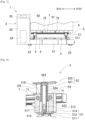
Fig. 2 is a side view of the autonomous transport vehicle before a weight acting portion operates. -
Fig. 3 is a side view of the autonomous transport vehicle in which the weight acting portion has operated below a transported object. -
Fig. 4 is a side cross-sectional view illustrating a state of an elastic support portion before the weight acting portion operates. -
Fig. 5 is a side view illustrating a state of the elastic support portion after the weight acting portion has operated. -
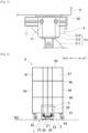
Fig. 6 is a front view illustrating a state in which the autonomous transport vehicle is traveling in a right-left direction while towing a transported object. -
Fig. 7 is a block diagram illustrating a configuration of control of the autonomous transport vehicle. -
Fig. 8 is a diagram conceptually illustrating a data format of transported object data set for each transported object. -
Fig. 9 is a diagram of an operation flow illustrating a transportation operation of autonomous transport vehicle. - First, an overall configuration of
autonomous transport vehicle 1 according to an embodiment will be described with reference toFigs. 1 to 3 . As indicated by an upper right arrow inFig. 1 , front, rear, right, and left sides ofautonomous transport vehicle 1 are defined for convenience.Autonomous transport vehicle 1 performs one of traveling with loading transportedobject 9 and traveling while towing transportedobject 9 based on a total weight and shape of transportedobject 9 different on a case-by-case basis.Autonomous transport vehicle 1 operates according to a transportation command including individual identification information of transportedobject 9 and a current position and target position of transportedobject 9.Autonomous transport vehicle 1 includesvehicle body 2 andweight acting portion 3. -
Vehicle body 2 includesloading platform portion 21 on a front side and drivingportion 22 on a rear side. Loadingplatform portion 21 is formed in a thin rectangular parallelepiped shape that has a substantially rectangular shape elongated in a front-rear direction in plan view and has a small height dimension. Loadingplatform portion 21 enters a lower side of transportedobject 9 to be transported.Driving portion 22 is formed in a vertically long rectangular parallelepiped shape that has the same width dimension as a width dimension ofloading platform portion 21 in a right-left direction, has a substantially rectangular shape elongated in the right-left direction in plan view, and has a large height dimension. Forloading platform portion 21 and drivingportion 22, heights of bottom surfaces have been aligned. -
Vehicle body 2 has fourtraveling wheels 23. As illustrated inFigs. 2 and3 , two travelingwheels 23 on the front side are disposed in a forward position of the bottom surface ofloading platform portion 21. Two travelingwheels 23 on the rear side are disposed on the bottom surface around a boundary betweenloading platform portion 21 and drivingportion 22. As travelingwheels 23, four omni wheels that are driven independently by different drive motors and have different axle directions at a pitch of 90° can be used. - In this aspect, four traveling wheels 23 (omni wheels) can rotate in mutually different rotation directions, and can rotate at mutually different rotation speeds. Accordingly, a traveling direction of
autonomous transport vehicle 1 is free. In addition,autonomous transport vehicle 1 is capable of traveling in various forms such as steering and spin turning. The number, a type, and an arrangement of travelingwheels 23 can be changed in various ways, without being limited thereto. - Further,
Vehicle body 2 includesbattery 24,control section 25,manual operation section 26, emergency stop buttons (27 and 29), andacquisition section 28.Battery 24 is disposed in a lower portion inside a housing ofdriving portion 22. The disposition ofbattery 24 having a large weight in a lower portion lowers a position of the center of gravity ofvehicle body 2 and improves stability.Battery 24 supplies power to the drive motors of travelingwheels 23,control section 25, and drive section 6 (described later) ofweight acting portion 3. -
Control section 25 is disposed in an upper portion inside the housing ofdriving portion 22.Control section 25 controls operations of the drive motors of travelingwheels 23 and operation ofweight acting portion 3 according to a transportation command (details will be described later). Further,control section 25 obtains a current position ofautonomous transport vehicle 1 based on a detection result of a position marker using a sensor (not shown) or the like, and further determines a future traveling route. In addition,control section 25 also estimates the current position based on a driving amount of travelingwheels 23. Accordingly, in a case where a ground contact load of travelingwheels 23 is insufficient and a slip (idling) occurs, estimation accuracy of the current position decreases. -
Manual operation section 26 is disposed on a left side of an upper surface of drivingportion 22, and is connected to controlsection 25.Manual operation section 26 functions in a case where a predetermined safety condition is satisfied, and a command by a manual operation of a worker is input thereto. The predetermined safety condition is satisfied, for example, in a case where a temporary stop command is transmitted toautonomous transport vehicle 1 andautonomous transport vehicle 1 temporarily stops. Further, as a command based on a manual operation, a command for canceling a transportation command set in advance inautonomous transport vehicle 1, a command for changing a target position, or the like can be exemplified. - First
emergency stop button 27 is disposed at a left rear end of the upper surface of drivingportion 22. Secondemergency stop button 29 is disposed on a front surface ofloading platform portion 21. In a case where emergency stop button (27 or 29) is pressed by the worker or another person, a power supply circuit connecting the drive motors of travelingwheels 23 andbattery 24 is cut off, andautonomous transport vehicle 1 stops in an emergency. Further, an approach detection sensor (not shown) may be provided invehicle body 2. The approach detection sensor detects an approach of anotherautonomous transport vehicle 1, the worker, or the like and outputs a detection signal to controlsection 25. Upon receiving the detection signal,control section 25 stopsautonomous transport vehicle 1 or reduces a traveling speed. Accordingly, interference betweenautonomous transport vehicles 1 and contact betweenautonomous transport vehicle 1 and the worker are avoided. -
Acquisition section 28 is disposed on a left side ofemergency stop button 29 on the front surface ofloading platform portion 21.Acquisition section 28 acquires the individual identification information for identifying an individual of transportedobject 9. In the present embodiment, a two-dimensional code indicating individual identification information is displayed on transportedobject 9. Meanwhile, a camera can be used asacquisition section 28. Acquisition section 28 (camera) acquires the individual identification information by imaging and reading the two-dimensional code displayed on transportedobject 9.Acquisition section 28 can perform an imaging operation while moving with respect to transportedobject 9 whileautonomous transport vehicle 1 is traveling.Acquisition section 28 sends the acquired individual identification information to controlsection 25. - Note that
acquisition section 28 including a camera may also be used for detecting an obstacle in front during traveling. Further,acquisition section 28 is not limited to the above-described camera. For example, transportedobject 9 may include a wireless tag that transmits a wireless signal indicating the individual identification information, andacquisition section 28 may be a wireless reception section that receives the wireless signal. - The maximum load weight of
autonomous transport vehicle 1 is determined in consideration of traveling stability ofautonomous transport vehicle 1, mechanical strength ofvehicle body 2 and travelingwheels 23, and the like. Further, the maximum towing weight is determined in consideration of traveling driving forces of the drive motors that drives travelingwheels 23, an own weight ofvehicle body 2, and the like. Further, the maximum load weight or the maximum towing weight may be determined in consideration of the maximum inclination angle or quality of a road surface condition of a traveling road on whichautonomous transport vehicle 1 travels. Of course, the maximum towing weight is larger than the maximum load weight. In a case whereautonomous transport vehicle 1 travels while towing transportedobject 9 having a relatively large total weight, it is important to appropriately maintain the ground contact load of travelingwheels 23 from the viewpoint of traveling stability. - Next, a configuration of
weight acting portion 3 will be described with reference toFigs. 1 to 5 .Weight acting portion 3 is provided on an upper portion ofloading platform portion 21 and enters the lower side of transportedobject 9.Weight acting portion 3 causes the total weight or partial weight of transportedobject 9 to act onloading platform portion 21 ofvehicle body 2 from transportedobject 9. To cause the total weight of transportedobject 9 to act onloading platform portion 21 means transportation with loading. To cause a partial weight of transportedobject 9 to act onloading platform portion 21 means that a remaining weight is borne by transportedobject 9 itself, in other words, transportation while towing transportedobject 9.Weight acting portion 3 includescommon base 4, four sets ofelastic support portions 5, drive section 6 (refer toFig. 7 ), and the like, and two connectingmembers 7 are attached thereto. -
Common base 4 is a substantially rectangular plate-shaped member that occupies the majority of an upper surface area ofloading platform portion 21.Common base 4 is formed of a thick member, and has high rigidity due to addition of a reinforcing member. In a case of being driven bydrive section 6,common base 4 is lifted and lowered while maintaining a horizontal state.Common base 4 is lowered (refer toFigs. 1 and 2 ) under a normal condition, and is driven to be lifted in a case of transporting transported object 9 (refer toFig. 3 ). Asdrive section 6, a combination of a motor and a cam mechanism can be exemplified, and another mechanism such as a hydraulic drive mechanism can also be used. - Four sets of
elastic support portions 5 are respectively disposed in the vicinity of four corners ofcommon base 4. The number of sets ofelastic support portions 5 is not limited to four sets, and can be changed.Elastic support portions 5 are provided onloading platform portion 21 viacommon base 4 so as to be capable of being lifted and lowered, and support transportedobject 9 from the lower side viaelastic body 53. As illustrated inFig. 4 , each ofelastic support portions 5 includesbase body 51,support body 52, andelastic body 53. -
Base body 51 is formed ofbase member 511,bottom plate member 512,cylinder member 514, and the like.Base member 511 is formed to have a large bottom portion and a small upper portion, and a reinforcing stay whose reference numeral is omitted is added. The bottom portion ofbase member 511 is fixed tocommon base 4.Bottom plate member 512 is a rectangular plate-shaped member.Bottom plate member 512 is horizontally fixed to an upper side ofbase member 511.Support pin 513 is disposed to stand upward at a center ofbottom plate member 512 and is fixed using a fastening screw whose reference numeral is omitted.Cylinder member 514 is a member which has a central axis extending in a vertical direction and in whichcylinder space 515 having an opening in an up-down direction is formed.Cylinder member 514 is fixed to an upper side ofbottom plate member 512.Cylinder space 515 is formed in a stepped cylindrical shape having small-diameter portion 516 on an upper side and a large-diameter portion 517 on a lower side. -
Support body 52 is formed ofpiston member 521,support member 525, and the like.Piston member 521 is a bottomed cylindrical member having a central axis common tocylinder member 514. Specifically,piston member 521 hasbottom portion 522 at an upper portion ofcylindrical portion 524, and a lower portion ofcylindrical portion 524 is flange 523 having an increased diameter.Support member 525 is a circular plate-shaped member.Support member 525 is horizontally disposed on an upper side ofbottom portion 522 ofpiston member 521, and is fixed using a fastening screw whose reference numeral is omitted.Support member 525 supports a bottom portion of transported object 9 (a lower surface of bottom plate 91) from below. - A lower portion of
piston member 521 constitutingsupport body 52 is disposed incylinder space 515 ofcylinder member 514 so as to be capable of being lifted and lowered. Further,support member 525 constitutingsupport body 52 is disposed abovecylinder member 514.Bottom portion 522 andcylindrical portion 524 ofpiston member 521 can be lifted and lowered in small-diameter portion 516. Meanwhile,flange 523 ofpiston member 521 can be lifted and lowered in large-diameter portion 517, but cannot enter small-diameter portion 516. This preventssupport body 52 from being detached upward. -
Elastic body 53 is provided betweenbase body 51 andsupport body 52. Specifically,elastic body 53 is used in a form in which a coil spring (shown in a cylindrical shape for convenience inFig. 4 ) capable of expanding and contracting in the up-down direction is applied and a stress is generated by compression. A lower end ofelastic body 53 is supported by engagement ofsupport pin 513 ofbase body 51. An upper end ofelastic body 53 is pressed againstbottom portion 522 ofsupport body 52. An intermediate portion ofelastic body 53 is held insidecylindrical portion 524 ofsupport body 52, and is prevented from being deformed in a direction other than an expansion and contraction direction. In manufacture ofelastic support portion 5, afterpiston member 521 andelastic body 53 are incorporated intocylinder member 514,bottom plate member 512 withsupport pin 513 andsupport member 525 are attached. - As illustrated in
Fig. 4 , a stress generated inelastic body 53 is small at a lifted position ofsupport body 52 in which flange 523 is located at an upper end of large-diameter portion 517. Meanwhile, in a case whereelastic support portion 5 is driven to be lifted,support body 52 is lifted at the beginning. In a case wheresupport body 52 is further lifted and comes into contact with the lower side of transportedobject 9,support body 52 cannot be lifted thereafter. In a case whereelastic support portion 5 is further driven to be lifted,support body 52 maintains a height thereof, and is relatively lowered with reference tobase body 51. - Accordingly,
bottom portion 522 ofsupport body 52 receiving the weight of transportedobject 9 presseselastic body 53 downward to compresselastic body 53. As illustrated inFig. 5 ,support body 52 can be lowered to a predetermined lowered position with reference tobase body 51. At a predetermined lowered position,support member 525 is lowered by lowering stroke length DS (refer toFig. 4 ) and comes into contact withcylinder member 514. At the same time,flange 523 is lowered to the vicinity of a lower end of large-diameter portion 517. Alternatively,flange 523 may be lowered to the lower end of large-diameter portion 517 and come into contact withbottom plate member 512, andsupport member 525 may be lowered to a position close tocylinder member 514. - In a case where
support body 52 is lowered to the lowered position,elastic body 53 is compressed by lowering stroke length DS, and a stress equal to a predetermined weight is generated. This stress has a magnitude that is balanced with the weight acting onsupport body 52 from transportedobject 9. This stress acts onloading platform portion 21 viabase body 51 andcommon base 4. - In the present embodiment, the predetermined weight is determined to be one fourth of the maximum load weight of
autonomous transport vehicle 1. In other words, a sum of the predetermined weights of fourelastic bodies 53 matches the maximum load weight. Accordingly, stresses equal to the maximum load weight in total is generated in fourelastic bodies 53. In this case, an amount corresponding to the maximum load weight of the weight of transportedobject 9 acts onloading platform portion 21 from transportedobject 9 viaelastic support portion 5. A sum of the amount corresponding to the maximum load weight of transportedobject 9 and the own weight ofvehicle body 2 acts on four travelingwheels 23 to be the ground contact load. - Note that various factors such as a spring constant and lowering stroke length DS of
elastic body 53 are designed such that the above-described stress is generated. Even in this case, the stress generated in fourelastic bodies 53 may include some manufacturing errors resulting from a dimensional tolerance of the members, an operation error during an assembly operation, or the like. - Further, in a case where a lifting amount of
elastic support portion 5 is small,support body 52 is lowered by a stroke length shorter than lowering stroke length DS with reference tobase body 51. In other words,support body 52 may stop in the middle of being lowered, instead of being lowered to the predetermined lowered position. In this case, stresses equal to a partial weight smaller than the maximum load weight in total is generated in fourelastic bodies 53. In this case, an amount corresponding to the partial weight of the total weight of transportedobject 9 acts onloading platform portion 21 from transportedobject 9. A sum of the amount corresponding to the partial weight of transportedobject 9 and the own weight ofvehicle body 2 acts on four travelingwheels 23 to be the ground contact load. - Two connecting
members 7 respectively connect two front andrear base bodies 51. As connectingmember 7, for example, square rod-shaped section steel is used. Connectingmember 7 is fastened to front and rear base bodies 51 (cylinder members 514) using twofastening bolts 71. Connectingmember 7 is provided to increase mechanical rigidity. Four connectingmembers 7 may be disposed to be a rectangular shape, and right and leftbase bodies 51 may be connected together. Each of connectingmembers 7 haspressing portions 72 at two positions on an upper surface. Pressingportion 72 is provided to stand upward from the upper surface of connectingmember 7, and is formed in, for example, a conical shape or a round rod shape. An upper end of pressingportion 72 extends to a position higher than an upper surface of support body 52 (support member 525). - As illustrated in
Fig. 3 ,bottom plate 91 of transportedobject 9 is formed with contactedportion 92 protruding downward in a lattice shape. In a case whereloading platform portion 21 enters the lower side of transportedobject 9,common base 4 is lowered, and pressingportion 72 passes a lower side of contactedportion 92. Thereafter, in a case whereweight acting portion 3 operates, connectingmember 7 is lifted integrally withcommon base 4 andbase body 51. Accordingly, pressingportion 72 is lifted to a height of contactedportion 92. Then, asvehicle body 2 travels, pressingportion 72 comes into contact with contactedportion 92 from a lateral side and presses transportedobject 9. According to this, in both cases of loading and towing, transportedobject 9 does not go through a significant lateral skid with respect to fourelastic support portions 5, and is stably transported. - Here, there are cases where
autonomous transport vehicle 1 is traveling and suddenly stops because of some reasons. In this case, a large inertial force in a horizontal direction is generated because of a sudden stop of transportedobject 9, and acts on pressingportion 72 from contactedportion 92. In this case, since the large inertial force is divided and transmitted from pressingportion 72 to front andrear base bodies 51 via connectingmember 7, a deformation amount of front and rearelastic support portions 5 is small, and there is no concern of breakage. That is, by providing connectingmember 7, it is possible to increase the mechanical rigidity against the large inertial force from transportedobject 9 generated in a case whereautonomous transport vehicle 1 suddenly stops. - Next, an example of transported
object 9 will be described with reference toFig. 6 . In the present embodiment, transportedobject 9 is a roll container on which multiple packages can be placed, and is not limited thereto. As illustrated inFig. 6 , transported object 9 (roll container) includesbottom plate 91, twoside plates 94,top plate 95, twoinventory plates 96, andcurtain 97.Bottom plate 91, twoside plates 94, andtop plate 95 form a rectangular parallelepiped frame that has openings in front and rear. -
Bottom plate 91 has contactedportion 92 described above and fourcasters 93 whose traveling directions freely change. Further, the two-dimensional code (not shown) described above is displayed on front and rear sides ofbottom plate 91. A height of a bottom surface ofbottom plate 91 varies depending on individual differences of transported objects 9. Twoinventory plates 96 are disposed horizontally while being vertically separated so as to divide an inside of the frame into approximately three equal parts. Packages are placed on upper surfaces of twoinventory plates 96 andbottom plate 91.Curtain 97 is formed using a transparent and flexible resin sheet.Curtain 97 is disposed so as to cover front and rear sides of the frame in an openable and closable manner. - The total weight of transported
object 9 is obtained by adding an own weight of transportedobject 9 to a weight of the packages placed thereon. Accordingly, the total weight of transportedobject 9 varies depending on a type and the number of the packages placed on a case-by-case basis. Further, there are multiple types of transportedobjects 9 having different height dimensions. A height dimension of transportedobject 9 illustrated inFig. 6 is close to four times a height dimension ofautonomous transport vehicle 1, and it cannot be said that stability is good in a case where transportedobject 9 is loaded and transported. Accordingly, even in a case where transportedobject 9 is unloaded and the total weight of transportedobject 9 is smaller than the maximum load weight,autonomous transport vehicle 1 tows that transportedobject 9 without loading that transportedobject 9 and performs stable transportation. - In
Fig. 6 ,casters 93 of transportedobject 9 are oriented in a right-left direction of the drawing, andautonomous transport vehicle 1 travels on road surface RD while towing unloaded transportedobject 9 in the right-left direction. In a case where the traveling direction ofautonomous transport vehicle 1 changes, a traveling direction ofcasters 93 also changes accordingly, so thatautonomous transport vehicle 1 can stably travel even while towing transportedobject 9. Meanwhile,autonomous transport vehicle 1 transports a transported object having a relatively small height dimension and a total weight smaller than the maximum load weight by elevating the transported object from road surface RD and loading the transported object. - Next, a configuration related to control of
autonomous transport vehicle 1 will be described with reference toFigs. 7 and 8 together with management of transportedobject 9. As illustrated inFig. 7 ,control section 25 separately controls the four drive motors so as to separately control the rotation directions and the rotation speeds of four travelingwheels 23. Further,control section 25 is connected tomanual operation section 26, and receives a command by a manual operation of the worker. Further,control section 25 is connected toacquisition section 28 and receives the individual identification information of transportedobject 9 acquired byacquisition section 28. Further,control section 25 controls drivesection 6 ofweight acting portion 3. - Further,
control section 25 is wirelessly communicably connected to transportedobject management section 99. Transportedobject management section 99 manages operating of multiple transportedobjects 9 using transported object data DC illustrated inFig. 8 . Transported object data DC is set for each of multiple transported objects 9. Transported object data DC has a data format in which individual identification information ID is associated with other management information. In the present embodiment, the other management information includes seven items: current position information P1, target position information P2, package name NM, package weight information W2, own weight information W1, bottom portion height information HT, and loading possibility information YN. - Individual identification information ID is information displayed on each of transported
objects 9 as described above and acquired byacquisition section 28. Current position information P1 is information indicating the current position of transportedobject 9. As an expression format of current position information P1, for example, two-dimensional coordinate values of a field in whichautonomous transport vehicle 1 travels or position numbers of multiple stop positions at which transportedobject 9 is stopped or stored are used. Each position number is associated in advance with a two-dimensional coordinate value of the field. Target position information P2 is information indicating a position of a transport destination to whichautonomous transport vehicle 1 transports transportedobject 9. Target position information P2 is blank in a case where it is not necessary to transport transportedobject 9, and is set in a case where transportedobject 9 is transported. Target position information P2 is expressed in the same expression format as currentposition information P 1. - Package name NM is information obtained by encoding a name of the package placed on transported
object 9. Package weight information W2 is information corresponding to an added value obtained by adding each weight of the multiple packages placed on transportedobject 9. Package name NM and Package weight information W2 are sequentially updated by the worker or a work robot in a case where the worker or the work robot loads and unloads the packages. The four items are changing information that changes with time: current position information P1, target position information P2, package name NM, and package weight information W2. - Own weight information W1 is information on the own weight of transported
object 9. The total weight of transportedobject 9 can be automatically obtained by adding own weight information W1 and package weight information W2. Bottom portion height information HT is information indicating a height from road surface RD of eachbottom plate 91 of transportedobjects 9 having individual differences. Loading possibility information YN is information that determines whether transportation with loading is possible. For example, for transportedobject 9 having a large height dimension (refer toFig. 6 ), loading possibility information YN is set to "impossible to transport with loading". The three items are fixed information that does not change under a normal condition and may change in a case where transportedobject 9 is modified or repaired: own weight information W1, bottom portion height information HT, and loading possibility information YN. - Transported
object management section 99 transmits a transportation command including transported object data DC in which target position information P2 is set toautonomous transport vehicle 1.Autonomous transport vehicle 1 transports transportedobject 9 based on transported object data DC included in the transportation command. Transportedobject management section 99 may transmit a transportation command including multiple pieces of transported object data DC, andautonomous transport vehicle 1 may sequentially transport multiple transportedobjects 9 in accordance with an arrangement order of the multiple pieces of transported object data DC. - Next, the operation of
autonomous transport vehicle 1 will be described with reference toFig. 9 . The following description includes description of a towing and transportation method of the embodiment. An operation flow illustrated inFig. 9 is advanced mainly under the control ofcontrol section 25. In step S1 ofFig. 9 ,control section 25 receives a transportation command from transportedobject management section 99. In next step S2,control section 25 determines a transportation method for transportedobject 9 based on transported object data DC included in the transportation command. Specifically,control section 25 determines whether to load transportedobject 9 or to tow transportedobject 9, and determines an operation condition ofweight acting portion 3 in a case of towing transportedobject 9. - Specifically, in a case where loading possibility information YN included in transported object data DC indicates that "impossible to transport with loading",
control section 25 determines to tow transportedobject 9. Further, in a case where loading possibility information YN indicates "possible to transport with loading",control section 25 determines to load transportedobject 9 in a case where the total weight of transportedobject 9 is equal to or less than the maximum load weight, and determines to tow transportedobject 9 in a case where the total weight of transportedobject 9 exceeds the maximum load weight. Further, for example, in a case where the total weight of transportedobject 9 exceeds the maximum towing weight,control section 25 notifies transportedobject management section 99 that transportedobject 9 cannot be transported, and ends the operation flow. - In a case where it is determined that transported
object 9 is loaded,control section 25 determines a lifting amount that is large enough to elevate transportedobject 9 from road surface RD as a lifting amount by which drivesection 6 ofweight acting portion 3 causescommon base 4 to be lifted. Further, in a case where it is determined that transportedobject 9 is towed,control section 25 determines a lifting amount by which drivesection 6 causescommon base 4 to be lifted based on the total weight of transportedobject 9 and bottom portion height information HT. Determination patterns include following (1), (2), and (3), and (2) may be merged into (1). - (1) In a case where the total weight of transported
object 9 exceeds the maximum load weight (predetermined weight),control section 25 adds lowering stroke length DS to a separation distance betweensupport body 52 andbottom plate 91 of transportedobject 9 to obtain a lifting amount. In this case, in a case wherecommon base 4 is lifted, as illustrated inFig. 5 ,support body 52 is lowered to the lowered position with reference tobase body 51. Accordingly, the sum of the amount corresponding to the maximum load weight of transportedobject 9 and the own weight ofvehicle body 2 acts on four travelingwheels 23 to be the ground contact load. In consideration of a manufacturing error of the stress generated in fourelastic bodies 53, an error of unevenness of road surface RD, or the like,control section 25 may reduce the lifting amount by an amount corresponding to the error. Accordingly, it is possible to avoid a concern that a load exceeding the maximum load weight acts onloading platform portion 21. - (2) In a case where the total weight of transported
object 9 exceeds the maximum load weight but an excess amount is equal to or less than a predetermined reducible weight,control section 25 adds the above-described separation distance and a reduction stroke length obtained by multiplying lowering stroke length DS by a first reduction rate less than 1 to obtain a lifting amount. In this case, in a case wherecommon base 4 is lifted,support body 52 stops in the middle of being lowered, instead of being lowered to the lowered position with reference tobase body 51. Accordingly, the sum of the amount corresponding to the partial weight of transportedobject 9 and the own weight ofvehicle body 2 acts on four travelingwheels 23 to be the ground contact load. That is, in a case where an excess amount is not so large, it is not necessary to apply the maximum load weight from transportedobject 9 to travelingwheels 23, and a certain degree of reduction is allowed. Accordingly, for example, by setting the first reduction rate to 50%, a partial weight that is half the maximum load weight is applied from transportedobject 9 to travelingwheels 23 vialoading platform portion 21, thereby obtaining a sufficient ground contact load. - (3) In a case where the total weight of transported
object 9 is equal to or less than the maximum load weight,control section 25 adds the above-described separation distance and a stroke length obtained by multiplying lowering stroke length DS by a second reduction rate to obtain a lifting amount. The second reduction rate is set within a range in which transportedobject 9 is not elevated from road surface RD. For example, in a case where the total weight of transportedobject 9 is 60% of the maximum load weight, the second reduction rate is set to a range of 0% or more and less than 60% (refer to Hooke's law). In a case where the second reduction rate is 0%, transportedobject 9 is self-standing while bearing the total weight of transportedobject 9 and is pressed by pressingportion 72. Further, in a case where the second reduction rate approaches 60%,elastic body 53 is compressed by that amount, and most of the total weight of transportedobject 9 acts on travelingwheels 23 vialoading platform portion 21. - In next step S3,
autonomous transport vehicle 1 travels toward the current position of transportedobject 9 indicated by current position information P1. Step S3 can be executed in parallel with step S2. In step S4 during traveling,acquisition section 28 acquires the individual identification information of transportedobject 9 while approaching transportedobject 9 and sends the individual identification information to controlsection 25. In next step S5,control section 25 checks whether the individual identification information received fromacquisition section 28 matches individual identification information ID included in transported object data DC received from transportedobject management section 99. - In a case where two pieces of individual identification information ID do not match, and in a case where
acquisition section 28 cannot acquire the individual identification information from transportedobject 9, the execution of the operation flow branches to step S12. In step S12,control section 25 notifies transportedobject management section 99 that commanded transportedobject 9 is absent (not found), and ends the operation flow. - In step S6, in a case where two pieces of individual identification information ID match,
loading platform portion 21 andweight acting portion 3 ofautonomous transport vehicle 1 enter the lower side of transportedobject 9. In next step S7,weight acting portion 3 operates based on any one of the determination patterns (1) to (3) described above. In any one of the determination patterns,elastic support portion 5 and connectingmember 7 is lifted. Accordingly,support body 52 supportsbottom plate 91 of transportedobject 9, andelastic body 53 is compressed and deformed. Further, pressingportion 72 is lifted to a height at which pressingportion 72 can come in to contact with contactedportion 92 from the lateral side. Accordingly, transportedobject 9 is loaded onloading platform portion 21 and can be towed byloading platform portion 21. - In next step S8,
control section 25drives traveling wheels 23. Accordingly,autonomous transport vehicle 1 loads transportedobject 9 and travels to the target position indicated by target position information P2.Autonomous transport vehicle 1 travels to the target position while towing transportedobject 9 while pressingportion 72 presses contactedportion 92. - Here, in a case where the total weight of transported
object 9 exceeds the maximum load weight, the maximum load weight or the partial weight of the total weight of transportedobject 9 acts onloading platform portion 21 because of the action ofelastic support portion 5. According to this, the sum of the maximum load weight or partial weight of transportedobject 9 and the own weight ofvehicle body 2 acts on four travelingwheels 23 to be the ground contact load. Accordingly, a stable ground contact load of travelingwheels 23 can be secured, andautonomous transport vehicle 1 can transport transportedobject 9 while towing transportedobject 9. Further, even in a case where road surface RD of the traveling road has some unevenness or steps,autonomous transport vehicle 1 can transport transportedobject 9 while towing transportedobject 9. - Further, since the stable ground contact load is secured, traveling
wheels 23 is less likely to slip (idle). Accordingly, the estimation accuracy of the current position estimated from the driving amount of travelingwheels 23 does not decrease. - In next step S9,
weight acting portion 3 performs a releasing operation. That is,drive section 6 causecommon base 4 to perform a lowering operation to generate a separation distance betweensupport body 52 andbottom plate 91 of transportedobject 9. In next step S10,loading platform portion 21 andweight acting portion 3 exit from the lower side of transportedobject 9. Accordingly,autonomous transport vehicle 1 leaves transportedobject 9 at the target position and departs from transportedobject 9. In next step S11,control section 25 notifies transportedobject management section 99 that the commanded transportation has ended. Transportedobject management section 99 moves the content of target position information P2 to current position information P1 and makes target position information P2 blank. As a result, the operation flow corresponding to one transportation command is ended. - In
autonomous transport vehicle 1 of the embodiment,loading platform portion 21 ofvehicle body 2 is caused to enter the lower side of transportedobject 9, and the partial weight of transportedobject 9 is applied from transportedobject 9 toloading platform portion 21, so that a large load obtained by adding the partial weight of transportedobject 9 to the own weight ofvehicle body 2 acts as the ground contact load of travelingwheels 23. Accordingly, even in a case where the total weight of transportedobject 9 is different on a case-by-case basis, it is possible to secure the stable ground contact load of travelingwheels 23 to suppress a slip (idling), and it is possible to transport transportedobject 9 while towing transportedobject 9. - The predetermined weight can be set to be smaller than the maximum load weight. For example, the spring constant of
elastic body 53 is made smaller than that of the embodiment. According to this, it is possible to reliably avoid a concern that the load exceeding the maximum load weight acts onloading platform portion 21. Further, pressingportion 72 can be formed long and provided to directly stand uponcommon base 4. In this aspect, moment generated in pressingportion 72 is larger than that in the embodiment, and thus pressingportion 72 needs to be thickened, but connectingmember 7 can be omitted. Further, a combination of pressingportion 72 and contactedportion 92 can be replaced with another configuration capable of moving transportedobject 9 in the horizontal direction. For example, an engaging portion provided on a front surface of drivingportion 22 may be engaged with an engaged portion provided on a rear surface of transportedobject 9, andvehicle body 2 and transportedobject 9 may move together. - Further, it is not essential to estimate the current position based on the driving amount of traveling
wheels 23, andcontrol section 25 may obtain the current position only by detecting the position marker by the sensor and determine the future traveling route. Further, the data format of transported object data DC can be changed in various ways. For example, one item of information, the total weight of transportedobject 9, can be used instead of two items of information, package weight information W2 and own weight information W1. Further, the total weight of transportedobject 9 on which a package is placed may be measured, and a measured value of the total weight may be used as transported object data DC. Further, information indicating the height dimension of transportedobject 9 may be used instead of loading possibility information YN of transported object data DC. In this aspect,control section 25 determines whether loading is possible by comparing the height dimension of transportedobject 9 with a predetermined limit height dimension at which loading is possible. Various modifications and applications in addition to the embodiment are possible. - 1: autonomous transport vehicle, 2: vehicle body, 21: loading platform portion, 22: driving portion, 23: traveling wheel, 25: control section, 28: acquisition section, 3: weight acting portion, 4: common base, 5: elastic support portion, 51: base body, 52: support body, 53: elastic body, 6: drive section, 7: connecting member, 72: pressing portion, 9: transported object, 91: bottom plate, 92: contacted portion, 99: transported object management section, DC: transported object data, DS: lowering stroke length.
Claims (13)
- An autonomous transport vehicle comprising:a vehicle body that includes a traveling wheel, is configured to enter a lower side of a transported object, and is configured to travel while towing the transported object; anda weight acting portion configured to cause, in a case where a total weight of the transported object is larger than a predetermined weight, a partial weight of the total weight equal to or less than the predetermined weight to act on the vehicle body from the transported object.
- The autonomous transport vehicle according to claim 1, wherein
the weight acting portion includesan elastic support portion that is provided on the vehicle body so as to be capable of being lifted and lowered, and is configured to support the transported object from the lower side via an elastic body, anda drive section configured to lift the elastic support portion with respect to the vehicle body such that a stress generated in the elastic body becomes the partial weight. - The autonomous transport vehicle according to claim 2, whereinthe elastic support portion includesa base body that is provided on the vehicle body so as to be capable of being lifted and lowered,a support body that is provided on the base body so as to be capable of being lifted and lowered, and is configured to support the transported object from the lower side, andthe elastic body that is provided between the base body and the support body and in which the stress equal to the predetermined weight is generated in a case where the support body is lowered to a predetermined lowered position with reference to the base body, andthe drive section drives the base body to be lifted and lowered.
- The autonomous transport vehicle according to claim 3, wherein
the drive section lowers the support body to the lowered position with reference to the base body by lifting the base body. - The autonomous transport vehicle according to claim 3 or 4, wherein
a lifting amount of the base body is determined based on a height of a bottom portion of the transported object supported by the support body. - The autonomous transport vehicle according to any one of claims 3 to 5, wherein
the weight acting portion includesa common base provided with multiple sets of the base body, the support body, and the elastic body, andthe drive section configured to drive the common base to be lifted and lowered. - The autonomous transport vehicle according to any one of claims 3 to 6, wherein
the weight acting portion includes a connecting member configured to connect at least two base bodies. - The autonomous transport vehicle according to any one of claims 1 to 7, further comprising:
a pressing portion that is configured to come into contact with a contacted portion provided on the transported object from a lateral side, and is configured to press the transported object as the vehicle body travels. - The autonomous transport vehicle according to any one of claims 1 to 8, wherein
the predetermined weight is a maximum load weight at which the transported object is capable of being loaded and transported without being towed. - The autonomous transport vehicle according to claim 9, wherein
in a case where the total weight of the transported object is equal to or less than the maximum load weight, the weight acting portion causes a part of the total weight to act on the vehicle body from the transported object to cause the vehicle body to tow the transported object, or causes the total weight to act on the vehicle body from the transported object to cause the transported object to be loaded onto the vehicle body. - The autonomous transport vehicle according to any one of claims 1 to 10, whereinindividual identification information for identifying an individual of the transported object is set for each transported object, andthe autonomous transport vehicle further comprises an acquisition section configured to acquire the individual identification information.
- The autonomous transport vehicle according to claim 11, wherein
at least one piece of information from among information on the total weight of the transported object, information on a height of a bottom portion of the transported object into which the vehicle body enters, and information on whether the transported object is capable of being loaded and transported is associated with the individual identification information. - A towing and transportation method comprising:a vehicle body entering step of causing a vehicle body including a traveling wheel to enter a lower side of a transported object;a weight acting step of causing a partial weight of a total weight of the transported object equal to or less than a predetermined weight to act on the vehicle body from the transported object; anda traveling step of driving the traveling wheel such that the vehicle body travels while towing the transported object.
Applications Claiming Priority (1)
| Application Number | Priority Date | Filing Date | Title |
|---|---|---|---|
| PCT/JP2021/032295 WO2023032124A1 (en) | 2021-09-02 | 2021-09-02 | Autonomous transport vehicle and towing and transportation method |
Publications (3)
| Publication Number | Publication Date |
|---|---|
| EP4397563A1 true EP4397563A1 (en) | 2024-07-10 |
| EP4397563A4 EP4397563A4 (en) | 2024-11-13 |
| EP4397563B1 EP4397563B1 (en) | 2025-08-13 |
Family
ID=85412399
Family Applications (1)
| Application Number | Title | Priority Date | Filing Date |
|---|---|---|---|
| EP21956013.3A Active EP4397563B1 (en) | 2021-09-02 | 2021-09-02 | Autonomous transport vehicle and towing and transportation method |
Country Status (5)
| Country | Link |
|---|---|
| US (1) | US20240351502A1 (en) |
| EP (1) | EP4397563B1 (en) |
| JP (1) | JP7645387B2 (en) |
| CN (1) | CN117836197A (en) |
| WO (1) | WO2023032124A1 (en) |
Families Citing this family (1)
| Publication number | Priority date | Publication date | Assignee | Title |
|---|---|---|---|---|
| DE102024109342B4 (en) * | 2024-04-03 | 2025-11-27 | Fixture Tech Solutions Gmbh | Self-driving transport robot |
Family Cites Families (8)
| Publication number | Priority date | Publication date | Assignee | Title |
|---|---|---|---|---|
| JP5305810B2 (en) | 2008-09-26 | 2013-10-02 | 愛知機械テクノシステム株式会社 | Automated guided vehicle |
| DE102011080857A1 (en) * | 2010-12-21 | 2012-06-21 | Roland Fritz | Transportation trailer for attaching to electrical towing vehicle to form logistics train for transportation of e.g. palette for regulating storekeeping of goods, has lifting unit connected to power source of electrical towing vehicle |
| DE102017203514A1 (en) * | 2017-03-03 | 2018-09-20 | Robert Bosch Gmbh | Industrial truck with improved sensor concept and forklift system |
| JP6855995B2 (en) * | 2017-09-29 | 2021-04-07 | アイシン・エィ・ダブリュ株式会社 | Automated guided vehicle and unmanned transport system |
| JP6980637B2 (en) * | 2018-11-09 | 2021-12-15 | 株式会社東芝 | Automated guided vehicle, automatic guided vehicle control method, and program |
| JP7303660B2 (en) * | 2019-05-07 | 2023-07-05 | 株式会社オカムラ | carrier |
| US11420856B2 (en) * | 2019-12-27 | 2022-08-23 | Grey Orange Pte. Ltd. | Transport vehicle for transporting payloads |
| JP7500484B2 (en) * | 2021-03-22 | 2024-06-17 | 株式会社東芝 | Automated guided vehicles, automated guided vehicles systems and transport programs |
-
2021
- 2021-09-02 EP EP21956013.3A patent/EP4397563B1/en active Active
- 2021-09-02 WO PCT/JP2021/032295 patent/WO2023032124A1/en not_active Ceased
- 2021-09-02 CN CN202180101767.1A patent/CN117836197A/en active Pending
- 2021-09-02 US US18/683,460 patent/US20240351502A1/en active Pending
- 2021-09-02 JP JP2023544912A patent/JP7645387B2/en active Active
Also Published As
| Publication number | Publication date |
|---|---|
| JP7645387B2 (en) | 2025-03-13 |
| EP4397563B1 (en) | 2025-08-13 |
| WO2023032124A1 (en) | 2023-03-09 |
| EP4397563A4 (en) | 2024-11-13 |
| JPWO2023032124A1 (en) | 2023-03-09 |
| US20240351502A1 (en) | 2024-10-24 |
| CN117836197A (en) | 2024-04-05 |
Similar Documents
| Publication | Publication Date | Title |
|---|---|---|
| KR102123790B1 (en) | AGV with lifting apparatus and AGV operating system | |
| JP2620707B2 (en) | Lift-spoke type cargo handling equipment | |
| EP3532416B1 (en) | Movable platform and actuating attachment | |
| US20160297653A1 (en) | Driver-free transport vehicle for the transportation of heavy loads on carriages and method for operating the transport vehicle | |
| CN216512675U (en) | AGV fork truck | |
| JP2018111589A (en) | Horizontal transport cart | |
| JP2008266011A (en) | Dolly with very small lifting loading stage and multistory storage shelf | |
| JP7303660B2 (en) | carrier | |
| EP4397563B1 (en) | Autonomous transport vehicle and towing and transportation method | |
| WO2022215115A1 (en) | Moving body | |
| WO2024004065A1 (en) | Autonomous transport vehicle and towing and transportation method | |
| CN110550412A (en) | Intelligent driving transport tool, transport tool combination and control method | |
| JP6855995B2 (en) | Automated guided vehicle and unmanned transport system | |
| CN215158533U (en) | Intelligent driving transport tool and transport tool combination | |
| CN210559178U (en) | An AGV forklift | |
| CN112298401A (en) | logistics trolley | |
| CN212605547U (en) | logistics trolley | |
| CN208647011U (en) | A kind of automated guided vehicle | |
| EP4400453B1 (en) | Automatic movement device and delivery system | |
| KR102939780B1 (en) | Ground force control driving method of low-floor cage towing driving robot | |
| CN222780717U (en) | Transport goods shelf | |
| JP7441367B1 (en) | Method and system for determining abnormalities in trolleys | |
| CN113666306A (en) | Three-way forklift mast, mast processing and arranging method and forklift | |
| CN218662146U (en) | Material rack of AGV device | |
| CN216005108U (en) | Electric walking system of small-sized carrying equipment |
Legal Events
| Date | Code | Title | Description |
|---|---|---|---|
| STAA | Information on the status of an ep patent application or granted ep patent |
Free format text: STATUS: THE INTERNATIONAL PUBLICATION HAS BEEN MADE |
|
| PUAI | Public reference made under article 153(3) epc to a published international application that has entered the european phase |
Free format text: ORIGINAL CODE: 0009012 |
|
| STAA | Information on the status of an ep patent application or granted ep patent |
Free format text: STATUS: REQUEST FOR EXAMINATION WAS MADE |
|
| 17P | Request for examination filed |
Effective date: 20240227 |
|
| AK | Designated contracting states |
Kind code of ref document: A1 Designated state(s): AL AT BE BG CH CY CZ DE DK EE ES FI FR GB GR HR HU IE IS IT LI LT LU LV MC MK MT NL NO PL PT RO RS SE SI SK SM TR |
|
| A4 | Supplementary search report drawn up and despatched |
Effective date: 20241011 |
|
| RIC1 | Information provided on ipc code assigned before grant |
Ipc: B62D 63/02 20060101ALI20241007BHEP Ipc: B62D 33/10 20060101ALI20241007BHEP Ipc: B62D 33/077 20060101ALI20241007BHEP Ipc: B62D 33/02 20060101ALI20241007BHEP Ipc: B65G 1/00 20060101ALI20241007BHEP Ipc: B62D 53/00 20060101ALI20241007BHEP Ipc: B61B 13/00 20060101AFI20241007BHEP |
|
| DAV | Request for validation of the european patent (deleted) | ||
| DAX | Request for extension of the european patent (deleted) | ||
| GRAP | Despatch of communication of intention to grant a patent |
Free format text: ORIGINAL CODE: EPIDOSNIGR1 |
|
| STAA | Information on the status of an ep patent application or granted ep patent |
Free format text: STATUS: GRANT OF PATENT IS INTENDED |
|
| RIC1 | Information provided on ipc code assigned before grant |
Ipc: B66F 9/06 20060101ALI20250414BHEP Ipc: B65G 1/10 20060101ALI20250414BHEP Ipc: B62D 63/02 20060101ALI20250414BHEP Ipc: B62D 33/10 20060101ALI20250414BHEP Ipc: B62D 33/077 20060101ALI20250414BHEP Ipc: B62D 33/02 20060101ALI20250414BHEP Ipc: B65G 1/00 20060101ALI20250414BHEP Ipc: B62D 53/00 20060101ALI20250414BHEP Ipc: B61B 13/00 20060101AFI20250414BHEP |
|
| INTG | Intention to grant announced |
Effective date: 20250430 |
|
| GRAS | Grant fee paid |
Free format text: ORIGINAL CODE: EPIDOSNIGR3 |
|
| GRAA | (expected) grant |
Free format text: ORIGINAL CODE: 0009210 |
|
| STAA | Information on the status of an ep patent application or granted ep patent |
Free format text: STATUS: THE PATENT HAS BEEN GRANTED |
|
| P01 | Opt-out of the competence of the unified patent court (upc) registered |
Free format text: CASE NUMBER: APP_28730/2025 Effective date: 20250617 |
|
| AK | Designated contracting states |
Kind code of ref document: B1 Designated state(s): AL AT BE BG CH CY CZ DE DK EE ES FI FR GB GR HR HU IE IS IT LI LT LU LV MC MK MT NL NO PL PT RO RS SE SI SK SM TR |
|
| REG | Reference to a national code |
Ref country code: GB Ref legal event code: FG4D |
|
| REG | Reference to a national code |
Ref country code: CH Ref legal event code: EP |
|
| REG | Reference to a national code |
Ref country code: DE Ref legal event code: R096 Ref document number: 602021036417 Country of ref document: DE |
|
| REG | Reference to a national code |
Ref country code: IE Ref legal event code: FG4D |
|
| PGFP | Annual fee paid to national office [announced via postgrant information from national office to epo] |
Ref country code: DE Payment date: 20250910 Year of fee payment: 5 |
|
| PGFP | Annual fee paid to national office [announced via postgrant information from national office to epo] |
Ref country code: GB Payment date: 20250911 Year of fee payment: 5 |
|
| PGFP | Annual fee paid to national office [announced via postgrant information from national office to epo] |
Ref country code: AT Payment date: 20251020 Year of fee payment: 5 |
|
| REG | Reference to a national code |
Ref country code: NL Ref legal event code: MP Effective date: 20250813 |
|
| PG25 | Lapsed in a contracting state [announced via postgrant information from national office to epo] |
Ref country code: IS Free format text: LAPSE BECAUSE OF FAILURE TO SUBMIT A TRANSLATION OF THE DESCRIPTION OR TO PAY THE FEE WITHIN THE PRESCRIBED TIME-LIMIT Effective date: 20251213 |
|
| PG25 | Lapsed in a contracting state [announced via postgrant information from national office to epo] |
Ref country code: NO Free format text: LAPSE BECAUSE OF FAILURE TO SUBMIT A TRANSLATION OF THE DESCRIPTION OR TO PAY THE FEE WITHIN THE PRESCRIBED TIME-LIMIT Effective date: 20251113 |
|
| REG | Reference to a national code |
Ref country code: LT Ref legal event code: MG9D |
|
| PG25 | Lapsed in a contracting state [announced via postgrant information from national office to epo] |
Ref country code: PT Free format text: LAPSE BECAUSE OF FAILURE TO SUBMIT A TRANSLATION OF THE DESCRIPTION OR TO PAY THE FEE WITHIN THE PRESCRIBED TIME-LIMIT Effective date: 20251215 |
|
| PG25 | Lapsed in a contracting state [announced via postgrant information from national office to epo] |
Ref country code: FI Free format text: LAPSE BECAUSE OF FAILURE TO SUBMIT A TRANSLATION OF THE DESCRIPTION OR TO PAY THE FEE WITHIN THE PRESCRIBED TIME-LIMIT Effective date: 20250813 |
|
| PG25 | Lapsed in a contracting state [announced via postgrant information from national office to epo] |
Ref country code: NL Free format text: LAPSE BECAUSE OF FAILURE TO SUBMIT A TRANSLATION OF THE DESCRIPTION OR TO PAY THE FEE WITHIN THE PRESCRIBED TIME-LIMIT Effective date: 20250813 Ref country code: HR Free format text: LAPSE BECAUSE OF FAILURE TO SUBMIT A TRANSLATION OF THE DESCRIPTION OR TO PAY THE FEE WITHIN THE PRESCRIBED TIME-LIMIT Effective date: 20250813 |
|
| PG25 | Lapsed in a contracting state [announced via postgrant information from national office to epo] |
Ref country code: GR Free format text: LAPSE BECAUSE OF FAILURE TO SUBMIT A TRANSLATION OF THE DESCRIPTION OR TO PAY THE FEE WITHIN THE PRESCRIBED TIME-LIMIT Effective date: 20251114 |
|
| PG25 | Lapsed in a contracting state [announced via postgrant information from national office to epo] |
Ref country code: SE Free format text: LAPSE BECAUSE OF FAILURE TO SUBMIT A TRANSLATION OF THE DESCRIPTION OR TO PAY THE FEE WITHIN THE PRESCRIBED TIME-LIMIT Effective date: 20250813 |
|
| PG25 | Lapsed in a contracting state [announced via postgrant information from national office to epo] |
Ref country code: LV Free format text: LAPSE BECAUSE OF FAILURE TO SUBMIT A TRANSLATION OF THE DESCRIPTION OR TO PAY THE FEE WITHIN THE PRESCRIBED TIME-LIMIT Effective date: 20250813 |
|
| PG25 | Lapsed in a contracting state [announced via postgrant information from national office to epo] |
Ref country code: PL Free format text: LAPSE BECAUSE OF FAILURE TO SUBMIT A TRANSLATION OF THE DESCRIPTION OR TO PAY THE FEE WITHIN THE PRESCRIBED TIME-LIMIT Effective date: 20250813 Ref country code: BG Free format text: LAPSE BECAUSE OF FAILURE TO SUBMIT A TRANSLATION OF THE DESCRIPTION OR TO PAY THE FEE WITHIN THE PRESCRIBED TIME-LIMIT Effective date: 20250813 |
|
| PG25 | Lapsed in a contracting state [announced via postgrant information from national office to epo] |
Ref country code: RS Free format text: LAPSE BECAUSE OF FAILURE TO SUBMIT A TRANSLATION OF THE DESCRIPTION OR TO PAY THE FEE WITHIN THE PRESCRIBED TIME-LIMIT Effective date: 20251113 |
|
| PG25 | Lapsed in a contracting state [announced via postgrant information from national office to epo] |
Ref country code: ES Free format text: LAPSE BECAUSE OF FAILURE TO SUBMIT A TRANSLATION OF THE DESCRIPTION OR TO PAY THE FEE WITHIN THE PRESCRIBED TIME-LIMIT Effective date: 20250813 |
|
| REG | Reference to a national code |
Ref country code: AT Ref legal event code: MK05 Ref document number: 1824400 Country of ref document: AT Kind code of ref document: T Effective date: 20250813 |
|
| PG25 | Lapsed in a contracting state [announced via postgrant information from national office to epo] |
Ref country code: RO Free format text: LAPSE BECAUSE OF FAILURE TO SUBMIT A TRANSLATION OF THE DESCRIPTION OR TO PAY THE FEE WITHIN THE PRESCRIBED TIME-LIMIT Effective date: 20250813 |
|
| PG25 | Lapsed in a contracting state [announced via postgrant information from national office to epo] |
Ref country code: SM Free format text: LAPSE BECAUSE OF FAILURE TO SUBMIT A TRANSLATION OF THE DESCRIPTION OR TO PAY THE FEE WITHIN THE PRESCRIBED TIME-LIMIT Effective date: 20250813 |
|
| PG25 | Lapsed in a contracting state [announced via postgrant information from national office to epo] |
Ref country code: DK Free format text: LAPSE BECAUSE OF FAILURE TO SUBMIT A TRANSLATION OF THE DESCRIPTION OR TO PAY THE FEE WITHIN THE PRESCRIBED TIME-LIMIT Effective date: 20250813 |
|
| PG25 | Lapsed in a contracting state [announced via postgrant information from national office to epo] |
Ref country code: AT Free format text: LAPSE BECAUSE OF FAILURE TO SUBMIT A TRANSLATION OF THE DESCRIPTION OR TO PAY THE FEE WITHIN THE PRESCRIBED TIME-LIMIT Effective date: 20250813 |
|
| PG25 | Lapsed in a contracting state [announced via postgrant information from national office to epo] |
Ref country code: IT Free format text: LAPSE BECAUSE OF FAILURE TO SUBMIT A TRANSLATION OF THE DESCRIPTION OR TO PAY THE FEE WITHIN THE PRESCRIBED TIME-LIMIT Effective date: 20250813 |
|
| PG25 | Lapsed in a contracting state [announced via postgrant information from national office to epo] |
Ref country code: CZ Free format text: LAPSE BECAUSE OF FAILURE TO SUBMIT A TRANSLATION OF THE DESCRIPTION OR TO PAY THE FEE WITHIN THE PRESCRIBED TIME-LIMIT Effective date: 20250813 |
|
| PG25 | Lapsed in a contracting state [announced via postgrant information from national office to epo] |
Ref country code: EE Free format text: LAPSE BECAUSE OF FAILURE TO SUBMIT A TRANSLATION OF THE DESCRIPTION OR TO PAY THE FEE WITHIN THE PRESCRIBED TIME-LIMIT Effective date: 20250813 Ref country code: SK Free format text: LAPSE BECAUSE OF FAILURE TO SUBMIT A TRANSLATION OF THE DESCRIPTION OR TO PAY THE FEE WITHIN THE PRESCRIBED TIME-LIMIT Effective date: 20250813 |
|
| REG | Reference to a national code |
Ref country code: CH Ref legal event code: H13 Free format text: ST27 STATUS EVENT CODE: U-0-0-H10-H13 (AS PROVIDED BY THE NATIONAL OFFICE) Effective date: 20260504 |