EP4397558A1 - Vehicle control system and method - Google Patents
Vehicle control system and method Download PDFInfo
- Publication number
- EP4397558A1 EP4397558A1 EP23210536.1A EP23210536A EP4397558A1 EP 4397558 A1 EP4397558 A1 EP 4397558A1 EP 23210536 A EP23210536 A EP 23210536A EP 4397558 A1 EP4397558 A1 EP 4397558A1
- Authority
- EP
- European Patent Office
- Prior art keywords
- lane
- driving
- vehicle
- controller
- lane width
- Prior art date
- Legal status (The legal status is an assumption and is not a legal conclusion. Google has not performed a legal analysis and makes no representation as to the accuracy of the status listed.)
- Granted
Links
Images


Classifications
-
- B—PERFORMING OPERATIONS; TRANSPORTING
- B60—VEHICLES IN GENERAL
- B60W—CONJOINT CONTROL OF VEHICLE SUB-UNITS OF DIFFERENT TYPE OR DIFFERENT FUNCTION; CONTROL SYSTEMS SPECIALLY ADAPTED FOR HYBRID VEHICLES; ROAD VEHICLE DRIVE CONTROL SYSTEMS FOR PURPOSES NOT RELATED TO THE CONTROL OF A PARTICULAR SUB-UNIT
- B60W30/00—Purposes of road vehicle drive control systems not related to the control of a particular sub-unit, e.g. of systems using conjoint control of vehicle sub-units
- B60W30/10—Path keeping
- B60W30/12—Lane keeping
-
- B—PERFORMING OPERATIONS; TRANSPORTING
- B60—VEHICLES IN GENERAL
- B60W—CONJOINT CONTROL OF VEHICLE SUB-UNITS OF DIFFERENT TYPE OR DIFFERENT FUNCTION; CONTROL SYSTEMS SPECIALLY ADAPTED FOR HYBRID VEHICLES; ROAD VEHICLE DRIVE CONTROL SYSTEMS FOR PURPOSES NOT RELATED TO THE CONTROL OF A PARTICULAR SUB-UNIT
- B60W40/00—Estimation or calculation of non-directly measurable driving parameters for road vehicle drive control systems not related to the control of a particular sub unit, e.g. by using mathematical models
- B60W40/02—Estimation or calculation of non-directly measurable driving parameters for road vehicle drive control systems not related to the control of a particular sub unit, e.g. by using mathematical models related to ambient conditions
- B60W40/06—Road conditions
-
- B—PERFORMING OPERATIONS; TRANSPORTING
- B60—VEHICLES IN GENERAL
- B60W—CONJOINT CONTROL OF VEHICLE SUB-UNITS OF DIFFERENT TYPE OR DIFFERENT FUNCTION; CONTROL SYSTEMS SPECIALLY ADAPTED FOR HYBRID VEHICLES; ROAD VEHICLE DRIVE CONTROL SYSTEMS FOR PURPOSES NOT RELATED TO THE CONTROL OF A PARTICULAR SUB-UNIT
- B60W2420/00—Indexing codes relating to the type of sensors based on the principle of their operation
- B60W2420/40—Photo, light or radio wave sensitive means, e.g. infrared sensors
- B60W2420/403—Image sensing, e.g. optical camera
-
- B—PERFORMING OPERATIONS; TRANSPORTING
- B60—VEHICLES IN GENERAL
- B60W—CONJOINT CONTROL OF VEHICLE SUB-UNITS OF DIFFERENT TYPE OR DIFFERENT FUNCTION; CONTROL SYSTEMS SPECIALLY ADAPTED FOR HYBRID VEHICLES; ROAD VEHICLE DRIVE CONTROL SYSTEMS FOR PURPOSES NOT RELATED TO THE CONTROL OF A PARTICULAR SUB-UNIT
- B60W2520/00—Input parameters relating to overall vehicle dynamics
- B60W2520/06—Direction of travel
-
- B—PERFORMING OPERATIONS; TRANSPORTING
- B60—VEHICLES IN GENERAL
- B60W—CONJOINT CONTROL OF VEHICLE SUB-UNITS OF DIFFERENT TYPE OR DIFFERENT FUNCTION; CONTROL SYSTEMS SPECIALLY ADAPTED FOR HYBRID VEHICLES; ROAD VEHICLE DRIVE CONTROL SYSTEMS FOR PURPOSES NOT RELATED TO THE CONTROL OF A PARTICULAR SUB-UNIT
- B60W2552/00—Input parameters relating to infrastructure
- B60W2552/10—Number of lanes
-
- B—PERFORMING OPERATIONS; TRANSPORTING
- B60—VEHICLES IN GENERAL
- B60W—CONJOINT CONTROL OF VEHICLE SUB-UNITS OF DIFFERENT TYPE OR DIFFERENT FUNCTION; CONTROL SYSTEMS SPECIALLY ADAPTED FOR HYBRID VEHICLES; ROAD VEHICLE DRIVE CONTROL SYSTEMS FOR PURPOSES NOT RELATED TO THE CONTROL OF A PARTICULAR SUB-UNIT
- B60W2552/00—Input parameters relating to infrastructure
- B60W2552/20—Road profile, i.e. the change in elevation or curvature of a plurality of continuous road segments
-
- B—PERFORMING OPERATIONS; TRANSPORTING
- B60—VEHICLES IN GENERAL
- B60W—CONJOINT CONTROL OF VEHICLE SUB-UNITS OF DIFFERENT TYPE OR DIFFERENT FUNCTION; CONTROL SYSTEMS SPECIALLY ADAPTED FOR HYBRID VEHICLES; ROAD VEHICLE DRIVE CONTROL SYSTEMS FOR PURPOSES NOT RELATED TO THE CONTROL OF A PARTICULAR SUB-UNIT
- B60W2552/00—Input parameters relating to infrastructure
- B60W2552/53—Road markings, e.g. lane marker or crosswalk
-
- B—PERFORMING OPERATIONS; TRANSPORTING
- B60—VEHICLES IN GENERAL
- B60W—CONJOINT CONTROL OF VEHICLE SUB-UNITS OF DIFFERENT TYPE OR DIFFERENT FUNCTION; CONTROL SYSTEMS SPECIALLY ADAPTED FOR HYBRID VEHICLES; ROAD VEHICLE DRIVE CONTROL SYSTEMS FOR PURPOSES NOT RELATED TO THE CONTROL OF A PARTICULAR SUB-UNIT
- B60W2556/00—Input parameters relating to data
- B60W2556/40—High definition maps
-
- B—PERFORMING OPERATIONS; TRANSPORTING
- B60—VEHICLES IN GENERAL
- B60W—CONJOINT CONTROL OF VEHICLE SUB-UNITS OF DIFFERENT TYPE OR DIFFERENT FUNCTION; CONTROL SYSTEMS SPECIALLY ADAPTED FOR HYBRID VEHICLES; ROAD VEHICLE DRIVE CONTROL SYSTEMS FOR PURPOSES NOT RELATED TO THE CONTROL OF A PARTICULAR SUB-UNIT
- B60W50/00—Details of control systems for road vehicle drive control not related to the control of a particular sub-unit, e.g. process diagnostic or vehicle driver interfaces
- B60W50/02—Ensuring safety in case of control system failures, e.g. by diagnosing, circumventing or fixing failures
- B60W50/0205—Diagnosing or detecting failures; Failure detection models
-
- B—PERFORMING OPERATIONS; TRANSPORTING
- B60—VEHICLES IN GENERAL
- B60Y—INDEXING SCHEME RELATING TO ASPECTS CROSS-CUTTING VEHICLE TECHNOLOGY
- B60Y2300/00—Purposes or special features of road vehicle drive control systems
- B60Y2300/10—Path keeping
- B60Y2300/12—Lane keeping
Definitions
- the present disclosure relates to a vehicle control system and method for controlling a vehicle to keep driving in a current driving lane.
- An autonomous vehicle employs an advanced driver assistance system (ADAS) to free a driver from simple work, such as steering wheel and pedal manipulation during driving, and prevent accidents caused by a driver's carelessness. Therefore, people's interest therein is currently increasing.
- ADAS advanced driver assistance system
- the determining of the expected lane width may include: recognizing, by the controller, the driving lane ahead of the vehicle by utilizing image information obtained by the camera; and determining, by the controller, an expected lane width of the driving lane, based on information included in the driving lane recognized by the camera.
- the determining of whether the real lane width increases may include: determining, by the controller, a real lane width of the driving lane at a time point at which the expected lane width increases; and determining, by the controller, whether the determined real lane width increases within a pre-configured reference time from the time point.
- the determining of whether the real lane width increases may include: determining, by the controller, an increased amount of the expected lane width in a time interval in which the expected lane width increases; determining, by the controller, a changed amount of the real lane width of the driving lane in the time interval; and determining, by the controller, whether the real lane width increases, based on the changed amount of the real lane width and the increased amount of the expected lane width.
- the determining of whether the driving lane is the outermost lane may include: collecting, by the controller in response to the determination that the real lane width is increasing, at least one piece of information among information on the two lines of the driving lane, and information relating to existence or absence of a road edge with respect to both sides of the driving lane; and determining, by the controller, whether the driving lane is the outermost lane, by utilizing the collected at least one piece of information.
- a vehicle control system may include: a camera configured be in a vehicle and to capture an image of a foreground of the vehicle; and a controller configured to: recognize a driving lane, based on an image captured by the camera, determine an expected lane width of the driving lane over time, determine whether a real lane width of the driving lane increases at a time point at which the determined expected lane width increases, and control driving, based on information on a line, when it is determined that the real lane width increases, wherein the line is one among two lines of the driving lane and positioned opposite a side of the driving lane in which the lane width increases.
- the controller may be further configured to: determine an increased amount of the expected lane width in a time interval in which the expected lane width increases, determine a changed amount of the real lane width of the driving lane in the time interval, and determine whether the real lane width increases, based on the changed amount of the real lane width and the increased amount of the expected lane width.
- a singular expression may include a plural expression unless they are definitely different in a context.
- control unit is merely a term widely used for naming a controller configured to control a specific function of a vehicle, but does not mean a generic function unit.
- the controller may include a communication device configured to communicate with a sensor or another control unit, a memory configured to store an operation system, a logic command, or input/output information, and at least one processor configured to perform determination, calculation, decision or the like which are required for responsible function controlling.
- the determination unit 121 may determine that the vehicle has entered a stretch in which the driving lane in which the vehicle is driving expands. For example, when it is determined that an expected lane width and a real lane width increases, the determination unit 121 may determine that the vehicle has entered a stretch in which there is at least one lane among a diverged lane and an expanded lane of the driving lane in which the vehicle is driving.
- the determination unit 121 may determine whether the driving lane in which the vehicle is driving is the outermost lane. When it is determined that the real lane width increases, the determination unit 121 may collect at least one piece of information among information on both lines of the driving lane, and information relating to existence or absence of a road edge with respect to both sides of the driving lane. Thereafter, the determination unit 121 may determine whether the driving lane in which the vehicle is driving is the outermost lane, by using the collected at least one piece of information.
- the determination unit 121 may make mis-determination when determining whether a lane is the outermost lane. Therefore, when the driving lane is a single one-way lane, the determination unit 121 may determine which side, among both sides of the driving lane, to which an expected lane width and a real lane width increase more, based on the driving lane.
- the determination unit 121 may determine that at least one lane among a diverged lane and an expanded lane exists at a side to which the expected lane width and the real lane width increase more, and determine that the vehicle has entered a stretch in which there is at least one lane among the diverged lane and the expanded lane of the driving lane.
- the determination unit 121 may transfer a result of the determination to the information generation unit 122.
- the information generation unit 122 may generate driving control information of the vehicle, based on information of a line, among both lines of the driving lane, existing opposite to a side at which there is at least one lane among the diverged lane and the expanded lane. For example, the information generation unit 122 may generate driving control information of the vehicle, based on at least one piece of information among the offset, a heading angle, a curvature, and a curvature derivative value of a line, among both lines of the driving lane, existing opposite to a side at which there is at least one lane among the diverged lane and the expanded lane.
- this is an example, and it is obvious that various information other than the above information may be used to generate driving control information of a vehicle.
- the information generation unit 122 may output the generated driving control information of the vehicle to the driving control unit 123.
- the driving control information of the vehicle generated by the information generation unit 122 may differ from driving control information of the vehicle based on information of a driving lane line previously recognized by the camera 110, and this difference may make control of vehicle driving unstable. Therefore, before outputting the generated driving control information of the vehicle, the information generation unit 122 may reflect, on the driving control information, a correction value considering a change rate of the driving control information and then output the driving control information.
- the correction value may be a value configured by considering an upper limit value of a change rate of driving control information in order to prevent a rapid change between existing driving control information and generated driving control information.
- this is an example, and it is obvious that the disclosure is not necessarily limited thereto.
- the driving control unit 123 may control driving of the vehicle, based on driving control information of the vehicle output from the information generation unit 122. For example, the driving control unit 123 may control a steering device included in the vehicle, based on the output driving control information, such that the vehicle does not travel to the side at which there is at least one lane among the diverged lane and the expanded lane, and travels in the driving lane where the vehicle is originally driving.
- the controller 120 may be implemented as one function of an advanced driver assistance system (ADAS) controller controlling an ADAS.
- ADAS advanced driver assistance system
- the controller 120 may be implemented as a separate controller different from the ADAS controller, or may be implemented such that the functions thereof are disposed into two or more different controllers.
- the vehicle While the vehicle is driving in the driving lane, when the vehicle reaches point A, the vehicle may determine an expected lane width over time. Thereafter, if it is determined that the expected lane width increases at point B, when the vehicle reaches point B during driving, the vehicle may determine whether a real lane width increases.
- the vehicle may collect information on both lines of the driving lane in which the vehicle is driving, and information relating to existence or absence of a road edge with respect to both sides of the driving lane.
- a line (RL) positioned at the right side among both sides of the driving lane in which the vehicle is driving is determined as an unbroken line indicating lane change being impossible, or when a road edge exists at the right side among both sides of the driving lane, the vehicle may determine that the driving lane in which the vehicle is currently driving is the outermost lane.
- the vehicle may determine that the vehicle has entered a stretch of the driving lane in which there is at least one lane among a diverged lane and an expanded lane.
- FIG. 2 is used to describe an example in which a diverged lane exists, but the same application to an expanded lane is obviously possible.
- the vehicle may control driving thereof, based on information of a line LL existing opposite to the line RL, among both lines of the driving lane, at which the diverged lane exists.
- the vehicle may recognize a line LL, which faces, in a horizontal direction (Y direction), the line RL, among both lines of the driving lane, at which the diverged lane exists, and control driving of the vehicle, based on information of the line LL. If the vehicle passes point C, the vehicle becomes out of the stretch in which the diverged lane exists in the driving lane, and thus the vehicle may perform a previous driving control scheme again.
- the vehicle may only recognize, rather than the line RL connecting to the diverged lane, only the line LL which is opposite to the line RL and faces same in the horizontal direction, and control driving of the vehicle, based on information of the line LL. Therefore, even when the vehicle enters a stretch in which a diverged lane exists, a line of the diverged lane is not mis-recognized and a line of a driving lane in the vehicle is driving is recognized, whereby malfunction of vehicle driving control can be prevented and driving stability of the vehicle can be improved.
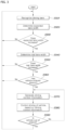
- FIG. 3 is a flowchart of a vehicle control method according to an embodiment of the present disclosure.
- an image of the foreground of a vehicle may be captured by means of the camera 110 included in the vehicle, and the controller 120 may recognize a driving lane in which the vehicle is currently driving, based on image information obtained by the camera 110 (operation S310), and may determine an expected lane width of the driving lane, based on recognized information (operation S320).
- the controller 120 may defer a process of determining whether the vehicle has entered the stretch in which there is at least one lane among the diverged lane and the expanded lane. In addition, even though the real lane width increases at the time point at which the expected lane width increases (Yes of operation S350), when the driving lane in which the vehicle is driving is not the outermost lane, or recognition of both lines of the driving lane fails, the controller 120 may determine that the vehicle has not entered the stretch in which there is at least one lane among the diverged lane and the expanded lane (No of operation S360).
- the controller 120 may recognize a line, among both lines of the driving lane, existing opposite to a side at which there is at least one lane among the diverged lane and the expanded lane.
- the controller 120 may generate driving control information of the vehicle, based on information of the recognized line (operation S370).
- the controller 120 may control driving of the vehicle, based on the generated driving control information, while driving in the stretch in which there is at least one lane among the diverged lane and the expanded lane (operation S380).
- the controller 120 may determine that the vehicle is out of the stretch in which there is at least one lane among the diverged lane and the expanded lane (Yes of operation S390). The controller 120 may perform corresponding control again, based on the driving lane recognized by the camera 110, or may terminate control.
- the present disclosure as described above may be implemented as codes in a computer-readable medium in which a program is recorded.
- the computer-readable medium includes all types of recording devices in which data readable by a computer system are stored. Examples of the computer-readable medium include a hard disk drive (HDD), a solid state disk (SSD), a silicon disk drive (SDD), a ROM, a RAM, a CD-ROM, a magnetic tape, a floppy disk, an optical data storage device, and the like.
Landscapes
- Engineering & Computer Science (AREA)
- Automation & Control Theory (AREA)
- Transportation (AREA)
- Mechanical Engineering (AREA)
- Physics & Mathematics (AREA)
- Mathematical Physics (AREA)
- Traffic Control Systems (AREA)
- Control Of Driving Devices And Active Controlling Of Vehicle (AREA)
Abstract
Description
- The present disclosure relates to a vehicle control system and method for controlling a vehicle to keep driving in a current driving lane.
- An autonomous vehicle employs an advanced driver assistance system (ADAS) to free a driver from simple work, such as steering wheel and pedal manipulation during driving, and prevent accidents caused by a driver's carelessness. Therefore, people's interest therein is currently increasing.
- The advanced driver assistance system includes a highway driving assist (HDA) function of assisting a vehicle to travel along the center of a driving lane, and lane following assist (KFA) and lane keeping assist (LKA) functions of assisting a vehicle not to deviate from the lines of a driving lane. When such functions are performed, a vehicle may recognize the lines of a driving lane, in which the vehicle is currently driving, by using a front camera included in the vehicle, and perform steering control along the recognized lines of the driving lane. Therefore, steering control performed by these kinds of assistance functions requires precise recognition of lines.
- However, when steering control is performed using only curvature information of a line of a driving lane, this may be problematic in that lines are mis-recognized due to diversity of a driving road environment in which a vehicle is driving, and steering is mis-controlled. For example, if there is a stretch diverged or expanded from a driving lane in which a vehicle is driving, when the vehicle enters the stretch, the vehicle misrecognizes a line of the diverged or expanded stretch as a line of the driving lane, and thus steering to the stretch may be performed.
- The foregoing described as the background is intended merely to aid in the understanding of the background of the present disclosure, and is not intended to mean that the present disclosure falls within the purview of the related art already known to those skilled in the art.
- The present disclosure has been made to solve such a problem, and is to provide a vehicle control system and method by which whether the lane width of a lane in which a vehicle is driving increases is determined, and driving of the vehicle is controlled on the basis of the determination.
- The technical subjects pursued in the present disclosure may not be limited to the above-mentioned technical subjects, and other technical subjects which are not mentioned may be clearly understood, through the following descriptions, by those skilled in the art to which the present disclosure pertains.
- In accordance with an aspect, a vehicle control method according to the present disclosure may include: recognizing, by a controller, a driving lane ahead of a vehicle by utilizing a camera included in the vehicle, and determining, by the controller, an expected lane width of the driving lane over time; determining, by the controller, whether a real lane width of the driving lane increases at a time point at which the determined expected lane width increases; and controlling driving, by the controller and in response to the determination that the real lane width is increasing, based on information on a line, wherein the line is one among two lines of the driving lane and positioned opposite a side of the driving lane in which the lane width increases.
- For example, the determining of the expected lane width may include: recognizing, by the controller, the driving lane ahead of the vehicle by utilizing image information obtained by the camera; and determining, by the controller, an expected lane width of the driving lane, based on information included in the driving lane recognized by the camera.
- For example, the determining of the expected lane width may further include determining, by the controller, an expected lane width of a driving lane recognized by the camera, based on a longitudinal distance of the vehicle and at least one piece of information among an offset, a heading angle, a curvature, and a curvature derivative value of the line.
- For example, the determining of whether the real lane width increases may include: determining, by the controller, a real lane width of the driving lane at a time point at which the expected lane width increases; and determining, by the controller, whether the determined real lane width increases within a pre-configured reference time from the time point.
- For example, the determining of whether the real lane width increases may include: determining, by the controller, an increased amount of the expected lane width in a time interval in which the expected lane width increases; determining, by the controller, a changed amount of the real lane width of the driving lane in the time interval; and determining, by the controller, whether the real lane width increases, based on the changed amount of the real lane width and the increased amount of the expected lane width.
- For example, the controlling of the driving may include determining, by the controller, that the vehicle has entered a stretch in which the driving lane includes at least one lane among a diverged lane and an expanded lane in response to the determination that the real lane width is increasing.
- For example, the controlling of the driving may further include: in response to the vehicle entering the stretch, generating, by the controller, driving control information of the vehicle, based on information of the line; and reflecting, by the controller, a pre-configured correction value on the generated driving control information and outputting the driving control information.
- For example, the generating of the driving control information may include generating, by the controller, driving control information of the vehicle, based on at least one piece of information among an offset, a heading angle, a curvature, and a curvature derivative value of the line.
- For example, the controlling of the driving may include: determining, by the controller and in response to the determination that the real lane width is increasing, whether the driving lane is an outermost lane; and determining, by the controller and in response to the driving lane being the outermost lane, that the vehicle has entered a stretch in which the driving lane includes at least one lane among a diverged lane and an expanded lane.
- For example, the determining of whether the driving lane is the outermost lane may include: collecting, by the controller in response to the determination that the real lane width is increasing, at least one piece of information among information on the two lines of the driving lane, and information relating to existence or absence of a road edge with respect to both sides of the driving lane; and determining, by the controller, whether the driving lane is the outermost lane, by utilizing the collected at least one piece of information.
- In addition, in accordance with the above aspect, a vehicle control system according to the present disclosure may include: a camera configured be in a vehicle and to capture an image of a foreground of the vehicle; and a controller configured to: recognize a driving lane, based on an image captured by the camera, determine an expected lane width of the driving lane over time, determine whether a real lane width of the driving lane increases at a time point at which the determined expected lane width increases, and control driving, based on information on a line, when it is determined that the real lane width increases, wherein the line is one among two lines of the driving lane and positioned opposite a side of the driving lane in which the lane width increases.
- For example, the controller may be further configured to: determine a real lane width of the driving lane at a time point at which the expected lane width increases, and determine whether the determined real lane width increases within a pre-configured reference time from the time point.
- For example, the controller may be further configured to: determine an increased amount of the expected lane width in a time interval in which the expected lane width increases, determine a changed amount of the real lane width of the driving lane in the time interval, and determine whether the real lane width increases, based on the changed amount of the real lane width and the increased amount of the expected lane width.
- For example, the controller may be further configured to: determine that the vehicle has entered a stretch in which the driving lane includes at least one lane among a diverged lane and an expanded lane, when it is determined that the real lane width increases, generate driving control information of the vehicle, based on information of the line, when it is determined that the vehicle has entered the stretch, reflect a pre-configured correction value on the generated driving control information, and output the driving control information.
- For example, the controller may be further configured to: determine whether the driving lane is an outermost lane when it is determined that the real lane width increases, and determine that the vehicle has entered a stretch in which the driving lane includes at least one lane among a diverged lane and an expanded lane when the driving lane is the outermost lane.
- According to a vehicle control system and method of the present disclosure, even when the lane width of a driving lane, in which a vehicle is driving, increases, a line positioned opposite to a side at which the lane width increases is recognized and driving of the vehicle is controlled, thereby preventing mis-controlling of lane following assist (LFA), lane keeping assist (LKA), and highway driving assist (HDA) functions which serve as transverse control in an advanced driver assistance system.
- Advantageous effects obtainable from the present disclosure may not be limited to the above-mentioned effects, and other effects which are not mentioned may be clearly understood, through the following descriptions, by those skilled in the art to which the present disclosure pertains.
-
-
FIG. 1 is a block diagram illustrating a configuration of a vehicle control system according to an embodiment of the present disclosure; -
FIG. 2 is a diagram illustrating control of a vehicle having entered a stretch in which a lane width increases, according to an embodiment of the present disclosure; and -
FIG. 3 is a flowchart of a vehicle control method according to an embodiment of the present disclosure. - In describing embodiments disclosed in the present specification, when the detailed description of the relevant known technology is determined to unnecessarily obscure the gist of the present disclosure, the detailed description may be omitted. Furthermore, the accompanying drawings are provided only for easy understanding of the embodiments disclosed in the present specification, and the technical spirit disclosed herein is not limited to the accompanying drawings, and it should be understood that all changes, equivalents, or substitutes thereof are included in the spirit and scope of the present disclosure.
- Terms including an ordinal number such as "first", "second", or the like may be used to describe various elements, but the elements are not limited to the terms. The above terms are used only for the purpose of distinguishing one element from another element.
- In the case where an element is referred to as being "connected" or "coupled" to any other element, it should be understood that another element may be provided therebetween, as well as that the element may be directly connected or coupled to the other element. In contrast, in the case where an element is "directly connected" or "directly coupled" to any other element, it should be understood that no other element is present therebetween.
- A singular expression may include a plural expression unless they are definitely different in a context.
- As used herein, the expression "include" or "have" are intended to specify the existence of mentioned features, numbers, steps, operations, elements, components, or combinations thereof, and should be construed as not precluding the possible existence or addition of one or more other features, numbers, steps, operations, elements, components, or combinations thereof.
- Hereinafter, embodiments disclosed in the present specification will be described in detail with reference to the accompanying drawings, and the same or similar elements are given the same and similar reference numerals, so duplicate descriptions thereof will be omitted.
- A unit or a control unit included in the name "control unit" is merely a term widely used for naming a controller configured to control a specific function of a vehicle, but does not mean a generic function unit. For example, the controller may include a communication device configured to communicate with a sensor or another control unit, a memory configured to store an operation system, a logic command, or input/output information, and at least one processor configured to perform determination, calculation, decision or the like which are required for responsible function controlling.
- First, referring to
FIG. 1 , a configuration of a vehicle control system according to an embodiment of the present disclosure is described. -
FIG. 1 is a block diagram illustrating a configuration of a vehicle control system according to an embodiment of the present disclosure. - Referring to
FIG. 1 , a vehicle control system according to an embodiment of the present disclosure may include acamera 110 and acontroller 120.FIG. 1 shows mainly elements related to an embodiment of the present disclosure, and thus it is obvious that fewer or more elements may be included when a real vehicle control system is implemented. - Hereinafter, each element will be described.
- The
camera 110 is an image capturing device mounted at a vehicle, and may be at least one camera among a front camera, a side camera, and a rear camera according to the position in which the camera is mounted. Thecamera 110 according to an embodiment of the present disclosure is assumed as a front camera mounted at a front of the vehicle. Thecamera 110 may be mounted at the front of the vehicle to capture an image of the foreground of the vehicle. In addition,multiple cameras 110 may be arranged at the front of the vehicle, and an image of the foreground of the vehicle may be captured by means of the multiple cameras. Thecamera 110 may collect image information obtained by capturing an image of the foreground of the vehicle, and provide the collected information to thecontroller 120. - The
controller 120 may recognize at least one piece of information among traffic information and road information, the traffic and roads of which are positioned ahead of the vehicle, based on the image information obtained by thecamera 110. For example, thecontroller 120 may recognize a driving lane ahead of the vehicle, in which the vehicle is driving. Thereafter, thecontroller 120 may control driving of the vehicle, based on information on the recognized driving lane. An aspect of the present disclosure is to, even in a case of occurrence of a change, such as increasing of the lane width of a driving lane in which a vehicle is driving, keep controlling the vehicle to travel in the current driving lane. Therefore, thecontroller 120 may determine an expected lane width of the driving lane over time, determine whether a real lane width of the driving lane increases at a time point at which the determined expected lane width increases, and when it is determined that the real lane width increases, control driving, based on information on a line, among both lines of the driving lane, positioned in an opposite direction of a direction in which the lane width increases. To this end, thecontroller 120 may include adetermination unit 121, aninformation generation unit 122, and adriving control unit 123. Hereinafter, each element will be described. - The
determination unit 121 may recognize a driving lane in image information provided from thecamera 110, and determine an expected lane width of the driving lane, based on information related to the recognized driving lane. Specifically, thedetermination unit 121 may determine an expected lane width of the driving lane, based on a longitudinal distance of the vehicle and at least one piece of information among an offset, a heading angle, a curvature, and a curvature derivative value of a line of the driving lane in information related to the recognized driving lane. - For example, the
determination unit 121 may determine an expected lane width through a line equation, based on a longitudinal distance of the vehicle and an offset, a heading angle, a curvature, and a curvature derivative value of a line of the driving lane. Thedetermination unit 121 may determine an expected lane width through a line equation as Equation 1 below.
- In Equation 1, X may denote a longitudinal distance of the vehicle, and Y may denote the distance from the vehicle to the left line or the right line. α may indicate an offset of the line, β may indicate a heading angle, γ may indicate the curvature of the line, δ may indicate the curvature derivative value of the line. In addition, the
determination unit 121 may apply the curvature and the curvature derivative value of the line in consideration of a correction factor. - The
determination unit 121 may determine an expected lane width over time through the described line equation, based on information related to a driving lane. That is, thedetermination unit 121 may determine an expected lane width that is expected over time with respect to a current location of the vehicle. For example, the expected lane width may be a value obtained by adding the distance from the vehicle to the left line and the distance from the vehicle to the right line, which are determined through Equation 1 described above, respectively. - As time passes, an offset, a heading angle, a curvature, and a curvature derivative value of a line of a driving lane in which the vehicle is driving and the longitudinal distance of the vehicle may change. Therefore, the expected lane width may be determined based on an offset, a heading angle, a curvature, and a curvature derivative value of a line, and the longitudinal distance of the vehicle which are obtained in consideration of a change over time. For example, an offset, a heading angle, a curvature, and a curvature derivative value of a driving lane line which are obtained in consideration of a change over time may be determined through Equation 2 below.

- Here, αk, βk, γk, and δk may denote an offset, a heading angle, a curvature, and a curvature derivative value of a line at a random time of k seconds, and α k+1 , β k+1 , γ k+1, and δ k+1 may denote an offset, a heading angle, a curvature, and a curvature derivative value of a line at a random time of (k+1) seconds. ΔX, ΔY, and Δθ may be determined through Equation 3 below.

- Here, ΔX may denote the longitudinal displacement of the vehicle for ΔT, ΔY may denote the transverse displacement of the vehicle for ΔT, and Δθ may denote the angle displacement in yaw of the pose of the vehicle for ΔT.
- Therefore, the
determination unit 121 may determine an expected lane width of a driving lane in which the vehicle is driving, over time through line equations including Equations 1 to 3. However, this is an example, and it is obvious that a method of determining an expected lane width of a driving lane is not limited to the method described above. For example, when an expected lane width of a driving lane is determined, information other than the above information of a line may be used, and the expected lane width may be determined through methods other than the line equations described above. - Furthermore, the
determination unit 121 may determine whether there is a time point at which a determined expected lane width increases, and when there is a time point at which the expected lane width increases, may determine a real lane width of the driving lane at the time point at which the expected lane width increases. If it is determined using only an expected lane width that the lane width of a driving lane in which the vehicle is driving increases, when line mis-recognition using thecamera 110 occurs, the expected lane width may be incorrectly determined as increasing. Therefore, in order to prevent this problem, thedetermination unit 121 may determine a real lane width when an expected lane width increases, to determine whether the real lane width also increases. For example, thedetermination unit 121 may determine a real lane width when an expected lane width increases, and determine whether the determined real lane width increases within a pre-configured reference time from a time point at which the expected lane width increases. - As another example, the
determination unit 121 may identify, in data of an expected lane width determined over time, a time interval in which the expected lane width increases, and determine an increased amount of the expected lane width in the time interval. Thereafter, thedetermination unit 121 may determine a changed amount of a real lane width of the driving lane in the time interval, and determine whether the real lane width increases, based on the changed amount of the real lane width and a changed amount of the expected lane width. - When it is determined that the real lane width also increases at a time point at which the expected lane width increases, the
determination unit 121 may determine that the vehicle has entered a stretch in which the driving lane in which the vehicle is driving expands. For example, when it is determined that an expected lane width and a real lane width increases, thedetermination unit 121 may determine that the vehicle has entered a stretch in which there is at least one lane among a diverged lane and an expanded lane of the driving lane in which the vehicle is driving. - In addition, when it is determined that the real lane width also increases at a time point at which the expected lane width increases, the
determination unit 121 may determine whether the driving lane in which the vehicle is driving is the outermost lane. When it is determined that the real lane width increases, thedetermination unit 121 may collect at least one piece of information among information on both lines of the driving lane, and information relating to existence or absence of a road edge with respect to both sides of the driving lane. Thereafter, thedetermination unit 121 may determine whether the driving lane in which the vehicle is driving is the outermost lane, by using the collected at least one piece of information. For example, thedetermination unit 121 may collect information relating to existence or absence of a road edge with respect to both sides of the driving lane, and when a road edge exists at one side among both sides of the driving lane, may determine that the driving lane in which the vehicle is currently driving is the outermost lane. In addition, thedetermination unit 121 may collect lane information including the shapes and colors of both lines of the driving lane, and when one line of both lines of the driving lane is a line configured by a single unbroken line indicating lane change being impossible, a line configured by double lines, or a line configured by a yellow unbroken line, may determine that the driving lane in which the vehicle is currently driving is the outermost lane. - When the driving lane in which the vehicle is driving is the outermost lane, the
determination unit 121 may determine that the vehicle has entered a stretch in which there is at least one lane among a diverged lane and an expanded lane of the driving lane. - Meanwhile, when the driving lane is a single one-way lane, road edges may exist at both sides of the driving lane, or both lines of the driving lane may be lines indicating lane change being impossible. Accordingly, the
determination unit 121 may make mis-determination when determining whether a lane is the outermost lane. Therefore, when the driving lane is a single one-way lane, thedetermination unit 121 may determine which side, among both sides of the driving lane, to which an expected lane width and a real lane width increase more, based on the driving lane. Thereafter, thedetermination unit 121 may determine that at least one lane among a diverged lane and an expanded lane exists at a side to which the expected lane width and the real lane width increase more, and determine that the vehicle has entered a stretch in which there is at least one lane among the diverged lane and the expanded lane of the driving lane. - When it is determined that the vehicle has entered a stretch in which there is at least one lane among the diverged lane and the expanded lane of the driving lane, the
determination unit 121 may transfer a result of the determination to theinformation generation unit 122. - When it is determined that the vehicle has entered the stretch, the
information generation unit 122 may generate driving control information of the vehicle, based on information of a line, among both lines of the driving lane, existing opposite to a side at which there is at least one lane among the diverged lane and the expanded lane. For example, theinformation generation unit 122 may generate driving control information of the vehicle, based on at least one piece of information among the offset, a heading angle, a curvature, and a curvature derivative value of a line, among both lines of the driving lane, existing opposite to a side at which there is at least one lane among the diverged lane and the expanded lane. However, this is an example, and it is obvious that various information other than the above information may be used to generate driving control information of a vehicle. - The
information generation unit 122 may output the generated driving control information of the vehicle to the drivingcontrol unit 123. When theinformation generation unit 122 outputs the generated driving control information, the driving control information of the vehicle generated by theinformation generation unit 122 may differ from driving control information of the vehicle based on information of a driving lane line previously recognized by thecamera 110, and this difference may make control of vehicle driving unstable. Therefore, before outputting the generated driving control information of the vehicle, theinformation generation unit 122 may reflect, on the driving control information, a correction value considering a change rate of the driving control information and then output the driving control information. For example, the correction value may be a value configured by considering an upper limit value of a change rate of driving control information in order to prevent a rapid change between existing driving control information and generated driving control information. However, this is an example, and it is obvious that the disclosure is not necessarily limited thereto. - The driving
control unit 123 may control driving of the vehicle, based on driving control information of the vehicle output from theinformation generation unit 122. For example, the drivingcontrol unit 123 may control a steering device included in the vehicle, based on the output driving control information, such that the vehicle does not travel to the side at which there is at least one lane among the diverged lane and the expanded lane, and travels in the driving lane where the vehicle is originally driving. - Meanwhile, in implementation of the
controller 120 according to an embodiment of the present disclosure, thecontroller 120 may be implemented as one function of an advanced driver assistance system (ADAS) controller controlling an ADAS. However, this is an example, and the disclosure is not necessarily limited thereto. For example, thecontroller 120 may be implemented as a separate controller different from the ADAS controller, or may be implemented such that the functions thereof are disposed into two or more different controllers. - Hereinafter, a vehicle to which a vehicle control system described above has been applied will be described with reference to
FIG. 2 . -
FIG. 2 is a diagram illustrating control of a vehicle having entered a stretch in which a lane width increases, according to an embodiment of the present disclosure. - Referring to
FIG. 2 , a vehicle is illustrated as moving in an X direction along a current driving lane. The vehicle illustrated inFIG. 2 may include a vehicle control system described with reference toFIG. 1 . - While the vehicle is driving in the driving lane, when the vehicle reaches point A, the vehicle may determine an expected lane width over time. Thereafter, if it is determined that the expected lane width increases at point B, when the vehicle reaches point B during driving, the vehicle may determine whether a real lane width increases.
- If the real lane width increases when the vehicle reaches point B, the vehicle may collect information on both lines of the driving lane in which the vehicle is driving, and information relating to existence or absence of a road edge with respect to both sides of the driving lane. When a line (RL) positioned at the right side among both sides of the driving lane in which the vehicle is driving is determined as an unbroken line indicating lane change being impossible, or when a road edge exists at the right side among both sides of the driving lane, the vehicle may determine that the driving lane in which the vehicle is currently driving is the outermost lane.
- When the expected lane width and the real lane width increase at point B, and the driving lane in which the vehicle is driving is the outermost lane, the vehicle may determine that the vehicle has entered a stretch of the driving lane in which there is at least one lane among a diverged lane and an expanded lane.
FIG. 2 is used to describe an example in which a diverged lane exists, but the same application to an expanded lane is obviously possible. - When a diverged lane exists at the right side in the driving lane of the vehicle, the diverged lane may be mis-recognized as the existing driving lane, and thus driving of the vehicle may be wrongly controlled. Therefore, when a diverged lane exists, the vehicle may control driving thereof, based on information of a line LL existing opposite to the line RL, among both lines of the driving lane, at which the diverged lane exists. In other words, when the vehicle enters a stretch in which a diverged lane exists, the vehicle may recognize a line LL, which faces, in a horizontal direction (Y direction), the line RL, among both lines of the driving lane, at which the diverged lane exists, and control driving of the vehicle, based on information of the line LL. If the vehicle passes point C, the vehicle becomes out of the stretch in which the diverged lane exists in the driving lane, and thus the vehicle may perform a previous driving control scheme again.
- That is, while driving the driving lane, when the vehicle enters a stretch (stretch between point B and point C) in which a diverged lane exists, the vehicle may only recognize, rather than the line RL connecting to the diverged lane, only the line LL which is opposite to the line RL and faces same in the horizontal direction, and control driving of the vehicle, based on information of the line LL. Therefore, even when the vehicle enters a stretch in which a diverged lane exists, a line of the diverged lane is not mis-recognized and a line of a driving lane in the vehicle is driving is recognized, whereby malfunction of vehicle driving control can be prevented and driving stability of the vehicle can be improved.
- Hereinafter, a vehicle control method according to an embodiment will be described with reference to
FIG. 3 , based on a configuration of a vehicle control system described above with reference toFIG. 1 . -
FIG. 3 is a flowchart of a vehicle control method according to an embodiment of the present disclosure. - Referring to
FIG. 3 , an image of the foreground of a vehicle may be captured by means of thecamera 110 included in the vehicle, and thecontroller 120 may recognize a driving lane in which the vehicle is currently driving, based on image information obtained by the camera 110 (operation S310), and may determine an expected lane width of the driving lane, based on recognized information (operation S320). - In determination of the expected lane width, when there is a time point at which the expected lane width increases (Yes of operation S330), the
controller 120 may determine a real lane width at the time point at which the expected lane width increases (operation S340). When the real lane width increases at the time point at which the expected lane width increases (Yes of operation S350), thecontroller 120 may determine, based on whether the driving lane in which the vehicle is driving is the outermost lane, whether the vehicle has entered a stretch in which there is at least one lane among a diverged lane and an expanded lane (operation S360). - If the real lane width does not increase at the time point at which the expected lane width increases (No of operation S350), the
controller 120 may defer a process of determining whether the vehicle has entered the stretch in which there is at least one lane among the diverged lane and the expanded lane. In addition, even though the real lane width increases at the time point at which the expected lane width increases (Yes of operation S350), when the driving lane in which the vehicle is driving is not the outermost lane, or recognition of both lines of the driving lane fails, thecontroller 120 may determine that the vehicle has not entered the stretch in which there is at least one lane among the diverged lane and the expanded lane (No of operation S360). - When the vehicle has entered the stretch in which there is at least one lane among the diverged lane and the expanded lane (Yes of operation S360), the
controller 120 may recognize a line, among both lines of the driving lane, existing opposite to a side at which there is at least one lane among the diverged lane and the expanded lane. Thecontroller 120 may generate driving control information of the vehicle, based on information of the recognized line (operation S370). Thecontroller 120 may control driving of the vehicle, based on the generated driving control information, while driving in the stretch in which there is at least one lane among the diverged lane and the expanded lane (operation S380). - Thereafter, the
controller 120 may determine whether the vehicle is out of the stretch in which there is at least one lane among the diverged lane and the expanded lane (operation S390). For example, thecontroller 120 may periodically measure a lane width, and when the lane width has been reduced to be similar to the lane width before the vehicle enters the stretch in which there is at least one lane among the diverged lane and the expanded lane, may determine that the vehicle is out of the stretch in which there is at least one lane among the diverged lane and the expanded lane (Yes of operation S390), and terminate control. In addition, when a longitudinal driving distance of the vehicle exceeds a pre-configured reference distance, thecontroller 120 may determine that the vehicle is out of the stretch in which there is at least one lane among the diverged lane and the expanded lane (Yes of operation S390). Thecontroller 120 may perform corresponding control again, based on the driving lane recognized by thecamera 110, or may terminate control. - Meanwhile, when the vehicle is still driving in the corresponding stretch without being out of the stretch in which there is at least one lane among the diverged lane and the expanded lane (No of operation S390), the
controller 120 may continuously perform control based on control information of the vehicle. - As described above, according to the present disclosure, even when the lane width of a driving lane in which a vehicle is driving increases, a line positioned opposite to a side at which the lane width increases is recognized and driving of the vehicle is controlled, whereby vehicle driving mis-control caused by lane width increment can be prevented, and stability of vehicle driving control can be ensured.
- Although the present disclosure has been described and illustrated in conjunction with particular embodiments thereof, it will be apparent to those skilled in the art that various improvements and modifications may be made to the present disclosure without departing from the technical idea of the present disclosure defined by the appended claims.
- The present disclosure as described above may be implemented as codes in a computer-readable medium in which a program is recorded. The computer-readable medium includes all types of recording devices in which data readable by a computer system are stored. Examples of the computer-readable medium include a hard disk drive (HDD), a solid state disk (SSD), a silicon disk drive (SDD), a ROM, a RAM, a CD-ROM, a magnetic tape, a floppy disk, an optical data storage device, and the like. Further, the above detailed description should not be construed in a limitative sense, but should be considered in an illustrative sense in all aspects. The scope of the present disclosure should not be determined by reasonable interpretation of the appended claims, and all changes and modifications within the equivalent scope of the present disclosure fall within the scope of the present disclosure.
Claims (15)
- A vehicle control method comprising:recognizing, by a controller, a driving lane ahead of a vehicle by utilizing a camera included in the vehicle, and determining, by the controller, an expected lane width of the driving lane over time;determining, by the controller, whether a real lane width of the driving lane increases at a time point at which the determined expected lane width increases; andcontrolling driving, by the controller and in response to the determination that the real lane width is increasing, based on information on a line, wherein the line is one among two lines of the driving lane and positioned opposite a side of the driving lane in which the lane width increases.
- The vehicle control method of claim 1, wherein the determining of the expected lane width comprises:recognizing, by the controller, the driving lane ahead of the vehicle by utilizing image information obtained by the camera; anddetermining, by the controller, an expected lane width of the driving lane, based on information included in the recognized driving lane.
- The vehicle control method of claim 2, wherein the determining of the expected lane width comprises determining, by the controller, an expected lane width of a driving lane recognized by the camera, based on a longitudinal distance of the vehicle and at least one information among an offset, a heading angle, a curvature, and a curvature derivative value of the line.
- The vehicle control method of any one of claims 1 to 3, wherein the determining of whether the real lane width increases comprises:determining, by the controller, a real lane width of the driving lane at a time point at which the expected lane width increases; anddetermining, by the controller, whether the determined real lane width increases within a pre-configured reference time from the time point.
- The vehicle control method of any one of claims 1 to 4, wherein the determining of whether the real lane width increases comprises:determining, by the controller, an increased amount of the expected lane width in a time interval in which the expected lane width increases;determining, by the controller, a changed amount of the real lane width of the driving lane in the time interval; anddetermining, by the controller, whether the real lane width increases, based on the changed amount of the real lane width and the increased amount of the expected lane width.
- The vehicle control method of any one of claims 1 to 5, wherein the controlling of the driving comprises determining, by the controller, that the vehicle has entered a stretch in which the driving lane includes at least one lane among a diverged lane and an expanded lane in response to the determination that the real lane width is increasing.
- The vehicle control method of claim 6, wherein the controlling of the driving comprises:in response to the vehicle entering the stretch, generating, by the controller, driving control information of the vehicle, based on information of the line; andreflecting, by the controller, a pre-configured correction value on the generated driving control information and outputting the driving control information.
- The vehicle control method of claim 7, wherein the generating of the driving control information comprises generating, by the controller, driving control information of the vehicle, based on at least one information among an offset, a heading angle, a curvature, and a curvature derivative value of the line.
- The vehicle control method of any one of claims 1 to 8, wherein the controlling of the driving comprises:determining, by the controller and in response to the determination that the real lane width is increasing, whether the driving lane is an outermost lane; anddetermining, by the controller and in response to the driving lane being the outermost lane, that the vehicle has entered a stretch in which the driving lane includes at least one lane among a diverged lane and an expanded lane.
- The vehicle control method of claim 9, wherein the determining of whether the driving lane is the outermost lane comprises:collecting, by the controller and in response to the determination that the real lane width is increasing, at least one piece of information among information on the two lines of the driving lane, and information relating to existence or absence of a road edge with respect to both sides of the driving lane; anddetermining, by the controller, whether the driving lane is an outermost lane, by utilizing the collected at least one piece of information.
- A vehicle control system comprising:a camera configured to be in a vehicle and to capture an image of a foreground of the vehicle; anda controller configured to:recognize a driving lane, based on an image captured by the camera,determine an expected lane width of the driving lane over time,determine whether a real lane width of the driving lane increases at a time point at which the determined expected lane width increases, andcontrol driving, based on information on a line, when it is determined that the real lane width increases, wherein the line is one among two lines of the driving lane and positioned opposite a side of the driving lane in which the lane width increases.
- The vehicle control system of claim 11, wherein the controller is further configured to:
determine a real lane width of the driving lane at a time point at which the expected lane width increases, and determine whether the determined real lane width increases within a pre-configured reference time from the time point. - The vehicle control system of claim 11 or 12, wherein the controller is further configured to:determine an increased amount of the expected lane width in a time interval in which the expected lane width increases, determine a changed amount of the real lane width of the driving lane in the time interval, anddetermine whether the real lane width increases, based on the changed amount of the real lane width and the increased amount of the expected lane width.
- The vehicle control system of any one of claims 11 to 13, wherein the controller is further configured to:determine that the vehicle has entered a stretch in which the driving lane includes at least one lane among a diverged lane and an expanded lane, when it is determined that the real lane width increases,generate driving control information of the vehicle, based on information of the line, when it is determined that the vehicle has entered the stretch,reflect a pre-configured correction value on the generated driving control information, andoutput the driving control information.
- The vehicle control system of any one of claims 11 to 14, wherein the controller is further configured to:determine whether the driving lane is an outermost lane when it is determined that the real lane width increases, anddetermine that the vehicle has entered a stretch in which the driving lane includes at least one lane among a diverged lane and an expanded lane when the driving lane is the outermost lane.
Applications Claiming Priority (1)
| Application Number | Priority Date | Filing Date | Title |
|---|---|---|---|
| KR1020230001402A KR20240109519A (en) | 2023-01-04 | 2023-01-04 | Control system and control method for vehicle |
Publications (2)
| Publication Number | Publication Date |
|---|---|
| EP4397558A1 true EP4397558A1 (en) | 2024-07-10 |
| EP4397558B1 EP4397558B1 (en) | 2025-08-27 |
Family
ID=88839423
Family Applications (1)
| Application Number | Title | Priority Date | Filing Date |
|---|---|---|---|
| EP23210536.1A Active EP4397558B1 (en) | 2023-01-04 | 2023-11-17 | Vehicle control system and method |
Country Status (4)
| Country | Link |
|---|---|
| US (1) | US20240217513A1 (en) |
| EP (1) | EP4397558B1 (en) |
| KR (1) | KR20240109519A (en) |
| CN (1) | CN118288991A (en) |
Citations (4)
| Publication number | Priority date | Publication date | Assignee | Title |
|---|---|---|---|---|
| US20080291276A1 (en) * | 2003-10-24 | 2008-11-27 | Martin Randler | Method for Driver Assistance and Driver Assistance Device on the Basis of Lane Information |
| US20150367778A1 (en) * | 2014-06-19 | 2015-12-24 | Toyota Motor Engineering & Manufacturing North America, Inc. | Road branch detection and path selection for lane centering |
| US20200070826A1 (en) * | 2018-08-28 | 2020-03-05 | Subaru Corporation | Lane keep control apparatus |
| DE102019107224A1 (en) * | 2019-03-21 | 2020-09-24 | Valeo Schalter Und Sensoren Gmbh | Driving assistance procedures |
Family Cites Families (1)
| Publication number | Priority date | Publication date | Assignee | Title |
|---|---|---|---|---|
| KR102374916B1 (en) | 2017-09-29 | 2022-03-16 | 주식회사 만도모빌리티솔루션즈 | Apparatus and Method for Controlling Lane-Keeping |
-
2023
- 2023-01-04 KR KR1020230001402A patent/KR20240109519A/en active Pending
- 2023-11-17 EP EP23210536.1A patent/EP4397558B1/en active Active
- 2023-11-27 US US18/519,333 patent/US20240217513A1/en active Pending
- 2023-12-12 CN CN202311703575.5A patent/CN118288991A/en active Pending
Patent Citations (4)
| Publication number | Priority date | Publication date | Assignee | Title |
|---|---|---|---|---|
| US20080291276A1 (en) * | 2003-10-24 | 2008-11-27 | Martin Randler | Method for Driver Assistance and Driver Assistance Device on the Basis of Lane Information |
| US20150367778A1 (en) * | 2014-06-19 | 2015-12-24 | Toyota Motor Engineering & Manufacturing North America, Inc. | Road branch detection and path selection for lane centering |
| US20200070826A1 (en) * | 2018-08-28 | 2020-03-05 | Subaru Corporation | Lane keep control apparatus |
| DE102019107224A1 (en) * | 2019-03-21 | 2020-09-24 | Valeo Schalter Und Sensoren Gmbh | Driving assistance procedures |
Also Published As
| Publication number | Publication date |
|---|---|
| KR20240109519A (en) | 2024-07-11 |
| CN118288991A (en) | 2024-07-05 |
| EP4397558B1 (en) | 2025-08-27 |
| US20240217513A1 (en) | 2024-07-04 |
Similar Documents
| Publication | Publication Date | Title |
|---|---|---|
| US11561103B2 (en) | Lane network data generation apparatus and storage medium | |
| US8560220B2 (en) | Method and apparatus for determining a plausible lane for guiding a vehicle and an automobile | |
| DE102012100164B4 (en) | Redundant lane determination systems for fault-tolerant vehicle lateral control devices | |
| US20220363250A1 (en) | Vehicular driving assistance system with lateral motion control | |
| US9734719B2 (en) | Method and apparatus for guiding a vehicle in the surroundings of an object | |
| US20080291276A1 (en) | Method for Driver Assistance and Driver Assistance Device on the Basis of Lane Information | |
| CN102069801A (en) | Lane-keeping control method and system | |
| CN112644489A (en) | Lane following control apparatus and method | |
| JP7605012B2 (en) | AUTONOMOUS DRIVING SYSTEM, AUTONOMOUS DRIVING CONTROL METHOD, AND AUTONOMOUS DRIVING CONTROL PROGRAM | |
| CN110949402A (en) | Alarm area determination method and device, storage medium and vehicle | |
| KR101950175B1 (en) | Method for estimating road line information | |
| US12291202B2 (en) | Lane keeping controller, vehicle system including the same, and method thereof | |
| US20200108868A1 (en) | Apparatus and method for controlling vehicle by determining distortion in lane recognition | |
| KR20200123505A (en) | Apparatus for controlling platooning of a vehicle, system having the same and method thereof | |
| CN110203197A (en) | A kind of lane identification and lane keeping method and terminal device | |
| JP2016218539A (en) | Vehicle runway recognition device | |
| EP3889721B1 (en) | Obstacle avoidance method and system during automatic driving of vehicle, and vehicle | |
| JP2002002427A (en) | Vehicle control device | |
| EP4397558B1 (en) | Vehicle control system and method | |
| CN113327456A (en) | Lane structure detection method and device | |
| CN208085705U (en) | A kind of lane center holding control system | |
| US12134433B2 (en) | Vehicle and control method thereof | |
| CN108701223B (en) | Apparatus and method for estimating the attention level of a driver of a vehicle | |
| US12600360B2 (en) | Vehicle and method of controlling the same | |
| JP7380735B2 (en) | Steering control device |
Legal Events
| Date | Code | Title | Description |
|---|---|---|---|
| PUAI | Public reference made under article 153(3) epc to a published international application that has entered the european phase |
Free format text: ORIGINAL CODE: 0009012 |
|
| STAA | Information on the status of an ep patent application or granted ep patent |
Free format text: STATUS: THE APPLICATION HAS BEEN PUBLISHED |
|
| AK | Designated contracting states |
Kind code of ref document: A1 Designated state(s): AL AT BE BG CH CY CZ DE DK EE ES FI FR GB GR HR HU IE IS IT LI LT LU LV MC ME MK MT NL NO PL PT RO RS SE SI SK SM TR |
|
| STAA | Information on the status of an ep patent application or granted ep patent |
Free format text: STATUS: REQUEST FOR EXAMINATION WAS MADE |
|
| 17P | Request for examination filed |
Effective date: 20241211 |
|
| GRAP | Despatch of communication of intention to grant a patent |
Free format text: ORIGINAL CODE: EPIDOSNIGR1 |
|
| STAA | Information on the status of an ep patent application or granted ep patent |
Free format text: STATUS: GRANT OF PATENT IS INTENDED |
|
| INTG | Intention to grant announced |
Effective date: 20250408 |
|
| P01 | Opt-out of the competence of the unified patent court (upc) registered |
Free format text: CASE NUMBER: APP_26856/2025 Effective date: 20250605 |
|
| GRAS | Grant fee paid |
Free format text: ORIGINAL CODE: EPIDOSNIGR3 |
|
| GRAA | (expected) grant |
Free format text: ORIGINAL CODE: 0009210 |
|
| STAA | Information on the status of an ep patent application or granted ep patent |
Free format text: STATUS: THE PATENT HAS BEEN GRANTED |
|
| AK | Designated contracting states |
Kind code of ref document: B1 Designated state(s): AL AT BE BG CH CY CZ DE DK EE ES FI FR GB GR HR HU IE IS IT LI LT LU LV MC ME MK MT NL NO PL PT RO RS SE SI SK SM TR |
|
| REG | Reference to a national code |
Ref country code: CH Ref legal event code: EP |
|
| REG | Reference to a national code |
Ref country code: DE Ref legal event code: R096 Ref document number: 602023006102 Country of ref document: DE |
|
| REG | Reference to a national code |
Ref country code: IE Ref legal event code: FG4D |
|
| REG | Reference to a national code |
Ref country code: NL Ref legal event code: MP Effective date: 20250827 |
|
| PG25 | Lapsed in a contracting state [announced via postgrant information from national office to epo] |
Ref country code: IS Free format text: LAPSE BECAUSE OF FAILURE TO SUBMIT A TRANSLATION OF THE DESCRIPTION OR TO PAY THE FEE WITHIN THE PRESCRIBED TIME-LIMIT Effective date: 20251227 |
|
| PGFP | Annual fee paid to national office [announced via postgrant information from national office to epo] |
Ref country code: DE Payment date: 20251118 Year of fee payment: 3 |
|
| PG25 | Lapsed in a contracting state [announced via postgrant information from national office to epo] |
Ref country code: NO Free format text: LAPSE BECAUSE OF FAILURE TO SUBMIT A TRANSLATION OF THE DESCRIPTION OR TO PAY THE FEE WITHIN THE PRESCRIBED TIME-LIMIT Effective date: 20251127 |
|
| REG | Reference to a national code |
Ref country code: LT Ref legal event code: MG9D |
|
| PG25 | Lapsed in a contracting state [announced via postgrant information from national office to epo] |
Ref country code: PT Free format text: LAPSE BECAUSE OF FAILURE TO SUBMIT A TRANSLATION OF THE DESCRIPTION OR TO PAY THE FEE WITHIN THE PRESCRIBED TIME-LIMIT Effective date: 20251229 |
|
| PG25 | Lapsed in a contracting state [announced via postgrant information from national office to epo] |
Ref country code: FI Free format text: LAPSE BECAUSE OF FAILURE TO SUBMIT A TRANSLATION OF THE DESCRIPTION OR TO PAY THE FEE WITHIN THE PRESCRIBED TIME-LIMIT Effective date: 20250827 |
|
| PG25 | Lapsed in a contracting state [announced via postgrant information from national office to epo] |
Ref country code: HR Free format text: LAPSE BECAUSE OF FAILURE TO SUBMIT A TRANSLATION OF THE DESCRIPTION OR TO PAY THE FEE WITHIN THE PRESCRIBED TIME-LIMIT Effective date: 20250827 Ref country code: NL Free format text: LAPSE BECAUSE OF FAILURE TO SUBMIT A TRANSLATION OF THE DESCRIPTION OR TO PAY THE FEE WITHIN THE PRESCRIBED TIME-LIMIT Effective date: 20250827 |
|
| PGFP | Annual fee paid to national office [announced via postgrant information from national office to epo] |
Ref country code: FR Payment date: 20251120 Year of fee payment: 3 |
|
| PG25 | Lapsed in a contracting state [announced via postgrant information from national office to epo] |
Ref country code: GR Free format text: LAPSE BECAUSE OF FAILURE TO SUBMIT A TRANSLATION OF THE DESCRIPTION OR TO PAY THE FEE WITHIN THE PRESCRIBED TIME-LIMIT Effective date: 20251128 |
|
| PG25 | Lapsed in a contracting state [announced via postgrant information from national office to epo] |
Ref country code: SE Free format text: LAPSE BECAUSE OF FAILURE TO SUBMIT A TRANSLATION OF THE DESCRIPTION OR TO PAY THE FEE WITHIN THE PRESCRIBED TIME-LIMIT Effective date: 20250827 |
|
| PG25 | Lapsed in a contracting state [announced via postgrant information from national office to epo] |
Ref country code: LV Free format text: LAPSE BECAUSE OF FAILURE TO SUBMIT A TRANSLATION OF THE DESCRIPTION OR TO PAY THE FEE WITHIN THE PRESCRIBED TIME-LIMIT Effective date: 20250827 |
|
| PG25 | Lapsed in a contracting state [announced via postgrant information from national office to epo] |
Ref country code: PL Free format text: LAPSE BECAUSE OF FAILURE TO SUBMIT A TRANSLATION OF THE DESCRIPTION OR TO PAY THE FEE WITHIN THE PRESCRIBED TIME-LIMIT Effective date: 20250827 Ref country code: BG Free format text: LAPSE BECAUSE OF FAILURE TO SUBMIT A TRANSLATION OF THE DESCRIPTION OR TO PAY THE FEE WITHIN THE PRESCRIBED TIME-LIMIT Effective date: 20250827 |
|
| PG25 | Lapsed in a contracting state [announced via postgrant information from national office to epo] |
Ref country code: RS Free format text: LAPSE BECAUSE OF FAILURE TO SUBMIT A TRANSLATION OF THE DESCRIPTION OR TO PAY THE FEE WITHIN THE PRESCRIBED TIME-LIMIT Effective date: 20251127 |
|
| PG25 | Lapsed in a contracting state [announced via postgrant information from national office to epo] |
Ref country code: ES Free format text: LAPSE BECAUSE OF FAILURE TO SUBMIT A TRANSLATION OF THE DESCRIPTION OR TO PAY THE FEE WITHIN THE PRESCRIBED TIME-LIMIT Effective date: 20250827 |
|
| REG | Reference to a national code |
Ref country code: AT Ref legal event code: MK05 Ref document number: 1829686 Country of ref document: AT Kind code of ref document: T Effective date: 20250827 |
|
| PG25 | Lapsed in a contracting state [announced via postgrant information from national office to epo] |
Ref country code: RO Free format text: LAPSE BECAUSE OF FAILURE TO SUBMIT A TRANSLATION OF THE DESCRIPTION OR TO PAY THE FEE WITHIN THE PRESCRIBED TIME-LIMIT Effective date: 20250827 |
|
| PG25 | Lapsed in a contracting state [announced via postgrant information from national office to epo] |
Ref country code: SM Free format text: LAPSE BECAUSE OF FAILURE TO SUBMIT A TRANSLATION OF THE DESCRIPTION OR TO PAY THE FEE WITHIN THE PRESCRIBED TIME-LIMIT Effective date: 20250827 |
|
| PG25 | Lapsed in a contracting state [announced via postgrant information from national office to epo] |
Ref country code: DK Free format text: LAPSE BECAUSE OF FAILURE TO SUBMIT A TRANSLATION OF THE DESCRIPTION OR TO PAY THE FEE WITHIN THE PRESCRIBED TIME-LIMIT Effective date: 20250827 |
|
| PG25 | Lapsed in a contracting state [announced via postgrant information from national office to epo] |
Ref country code: AT Free format text: LAPSE BECAUSE OF FAILURE TO SUBMIT A TRANSLATION OF THE DESCRIPTION OR TO PAY THE FEE WITHIN THE PRESCRIBED TIME-LIMIT Effective date: 20250827 |
|
| PG25 | Lapsed in a contracting state [announced via postgrant information from national office to epo] |
Ref country code: IT Free format text: LAPSE BECAUSE OF FAILURE TO SUBMIT A TRANSLATION OF THE DESCRIPTION OR TO PAY THE FEE WITHIN THE PRESCRIBED TIME-LIMIT Effective date: 20250827 |
|
| PG25 | Lapsed in a contracting state [announced via postgrant information from national office to epo] |
Ref country code: CZ Free format text: LAPSE BECAUSE OF FAILURE TO SUBMIT A TRANSLATION OF THE DESCRIPTION OR TO PAY THE FEE WITHIN THE PRESCRIBED TIME-LIMIT Effective date: 20250827 |
|
| PG25 | Lapsed in a contracting state [announced via postgrant information from national office to epo] |
Ref country code: EE Free format text: LAPSE BECAUSE OF FAILURE TO SUBMIT A TRANSLATION OF THE DESCRIPTION OR TO PAY THE FEE WITHIN THE PRESCRIBED TIME-LIMIT Effective date: 20250827 Ref country code: SK Free format text: LAPSE BECAUSE OF FAILURE TO SUBMIT A TRANSLATION OF THE DESCRIPTION OR TO PAY THE FEE WITHIN THE PRESCRIBED TIME-LIMIT Effective date: 20250827 |
|
| REG | Reference to a national code |
Ref country code: DE Ref legal event code: R097 Ref document number: 602023006102 Country of ref document: DE |
|
| PG25 | Lapsed in a contracting state [announced via postgrant information from national office to epo] |
Ref country code: LT Free format text: LAPSE BECAUSE OF FAILURE TO SUBMIT A TRANSLATION OF THE DESCRIPTION OR TO PAY THE FEE WITHIN THE PRESCRIBED TIME-LIMIT Effective date: 20250827 Ref country code: MC Free format text: LAPSE BECAUSE OF FAILURE TO SUBMIT A TRANSLATION OF THE DESCRIPTION OR TO PAY THE FEE WITHIN THE PRESCRIBED TIME-LIMIT Effective date: 20250827 |
|
| PLBE | No opposition filed within time limit |
Free format text: ORIGINAL CODE: 0009261 |
|
| STAA | Information on the status of an ep patent application or granted ep patent |
Free format text: STATUS: NO OPPOSITION FILED WITHIN TIME LIMIT |
|
| REG | Reference to a national code |
Ref country code: CH Ref legal event code: L10 Free format text: ST27 STATUS EVENT CODE: U-0-0-L10-L00 (AS PROVIDED BY THE NATIONAL OFFICE) Effective date: 20260708 |
|
| PG25 | Lapsed in a contracting state [announced via postgrant information from national office to epo] |
Ref country code: LU Free format text: LAPSE BECAUSE OF NON-PAYMENT OF DUE FEES Effective date: 20251117 |
|
| 26N | No opposition filed |
Effective date: 20260528 |