EP4397549A1 - Method for controlling a speed of a vehicle, control unit, computer program product, non-transitory computer readable storage medium, brake system, and vehicle - Google Patents
Method for controlling a speed of a vehicle, control unit, computer program product, non-transitory computer readable storage medium, brake system, and vehicle Download PDFInfo
- Publication number
- EP4397549A1 EP4397549A1 EP23150550.4A EP23150550A EP4397549A1 EP 4397549 A1 EP4397549 A1 EP 4397549A1 EP 23150550 A EP23150550 A EP 23150550A EP 4397549 A1 EP4397549 A1 EP 4397549A1
- Authority
- EP
- European Patent Office
- Prior art keywords
- vehicle
- braking
- determined
- speed value
- speed
- Prior art date
- Legal status (The legal status is an assumption and is not a legal conclusion. Google has not performed a legal analysis and makes no representation as to the accuracy of the status listed.)
- Granted
Links
Images


Classifications
-
- B—PERFORMING OPERATIONS; TRANSPORTING
- B60—VEHICLES IN GENERAL
- B60W—CONJOINT CONTROL OF VEHICLE SUB-UNITS OF DIFFERENT TYPE OR DIFFERENT FUNCTION; CONTROL SYSTEMS SPECIALLY ADAPTED FOR HYBRID VEHICLES; ROAD VEHICLE DRIVE CONTROL SYSTEMS FOR PURPOSES NOT RELATED TO THE CONTROL OF A PARTICULAR SUB-UNIT
- B60W40/00—Estimation or calculation of non-directly measurable driving parameters for road vehicle drive control systems not related to the control of a particular sub unit, e.g. by using mathematical models
- B60W40/10—Estimation or calculation of non-directly measurable driving parameters for road vehicle drive control systems not related to the control of a particular sub unit, e.g. by using mathematical models related to vehicle motion
- B60W40/105—Speed
-
- B—PERFORMING OPERATIONS; TRANSPORTING
- B60—VEHICLES IN GENERAL
- B60W—CONJOINT CONTROL OF VEHICLE SUB-UNITS OF DIFFERENT TYPE OR DIFFERENT FUNCTION; CONTROL SYSTEMS SPECIALLY ADAPTED FOR HYBRID VEHICLES; ROAD VEHICLE DRIVE CONTROL SYSTEMS FOR PURPOSES NOT RELATED TO THE CONTROL OF A PARTICULAR SUB-UNIT
- B60W30/00—Purposes of road vehicle drive control systems not related to the control of a particular sub-unit, e.g. of systems using conjoint control of vehicle sub-units
- B60W30/18—Propelling the vehicle
- B60W30/18009—Propelling the vehicle related to particular drive situations
-
- B—PERFORMING OPERATIONS; TRANSPORTING
- B60—VEHICLES IN GENERAL
- B60W—CONJOINT CONTROL OF VEHICLE SUB-UNITS OF DIFFERENT TYPE OR DIFFERENT FUNCTION; CONTROL SYSTEMS SPECIALLY ADAPTED FOR HYBRID VEHICLES; ROAD VEHICLE DRIVE CONTROL SYSTEMS FOR PURPOSES NOT RELATED TO THE CONTROL OF A PARTICULAR SUB-UNIT
- B60W30/00—Purposes of road vehicle drive control systems not related to the control of a particular sub-unit, e.g. of systems using conjoint control of vehicle sub-units
- B60W30/14—Adaptive cruise control
- B60W30/143—Speed control
- B60W30/146—Speed limiting
-
- B—PERFORMING OPERATIONS; TRANSPORTING
- B60—VEHICLES IN GENERAL
- B60T—VEHICLE BRAKE CONTROL SYSTEMS OR PARTS THEREOF; BRAKE CONTROL SYSTEMS OR PARTS THEREOF, IN GENERAL; ARRANGEMENT OF BRAKING ELEMENTS ON VEHICLES IN GENERAL; PORTABLE DEVICES FOR PREVENTING UNWANTED MOVEMENT OF VEHICLES; VEHICLE MODIFICATIONS TO FACILITATE COOLING OF BRAKES
- B60T7/00—Brake-action initiating means
- B60T7/12—Brake-action initiating means for automatic initiation; for initiation not subject to will of driver or passenger
-
- B—PERFORMING OPERATIONS; TRANSPORTING
- B60—VEHICLES IN GENERAL
- B60W—CONJOINT CONTROL OF VEHICLE SUB-UNITS OF DIFFERENT TYPE OR DIFFERENT FUNCTION; CONTROL SYSTEMS SPECIALLY ADAPTED FOR HYBRID VEHICLES; ROAD VEHICLE DRIVE CONTROL SYSTEMS FOR PURPOSES NOT RELATED TO THE CONTROL OF A PARTICULAR SUB-UNIT
- B60W10/00—Conjoint control of vehicle sub-units of different type or different function
- B60W10/04—Conjoint control of vehicle sub-units of different type or different function including control of propulsion units
-
- B—PERFORMING OPERATIONS; TRANSPORTING
- B60—VEHICLES IN GENERAL
- B60W—CONJOINT CONTROL OF VEHICLE SUB-UNITS OF DIFFERENT TYPE OR DIFFERENT FUNCTION; CONTROL SYSTEMS SPECIALLY ADAPTED FOR HYBRID VEHICLES; ROAD VEHICLE DRIVE CONTROL SYSTEMS FOR PURPOSES NOT RELATED TO THE CONTROL OF A PARTICULAR SUB-UNIT
- B60W10/00—Conjoint control of vehicle sub-units of different type or different function
- B60W10/04—Conjoint control of vehicle sub-units of different type or different function including control of propulsion units
- B60W10/08—Conjoint control of vehicle sub-units of different type or different function including control of propulsion units including control of electric propulsion units, e.g. motors or generators
-
- B—PERFORMING OPERATIONS; TRANSPORTING
- B60—VEHICLES IN GENERAL
- B60W—CONJOINT CONTROL OF VEHICLE SUB-UNITS OF DIFFERENT TYPE OR DIFFERENT FUNCTION; CONTROL SYSTEMS SPECIALLY ADAPTED FOR HYBRID VEHICLES; ROAD VEHICLE DRIVE CONTROL SYSTEMS FOR PURPOSES NOT RELATED TO THE CONTROL OF A PARTICULAR SUB-UNIT
- B60W10/00—Conjoint control of vehicle sub-units of different type or different function
- B60W10/18—Conjoint control of vehicle sub-units of different type or different function including control of braking systems
-
- B—PERFORMING OPERATIONS; TRANSPORTING
- B60—VEHICLES IN GENERAL
- B60W—CONJOINT CONTROL OF VEHICLE SUB-UNITS OF DIFFERENT TYPE OR DIFFERENT FUNCTION; CONTROL SYSTEMS SPECIALLY ADAPTED FOR HYBRID VEHICLES; ROAD VEHICLE DRIVE CONTROL SYSTEMS FOR PURPOSES NOT RELATED TO THE CONTROL OF A PARTICULAR SUB-UNIT
- B60W10/00—Conjoint control of vehicle sub-units of different type or different function
- B60W10/18—Conjoint control of vehicle sub-units of different type or different function including control of braking systems
- B60W10/184—Conjoint control of vehicle sub-units of different type or different function including control of braking systems with wheel brakes
- B60W10/188—Conjoint control of vehicle sub-units of different type or different function including control of braking systems with wheel brakes hydraulic brakes
-
- B—PERFORMING OPERATIONS; TRANSPORTING
- B60—VEHICLES IN GENERAL
- B60W—CONJOINT CONTROL OF VEHICLE SUB-UNITS OF DIFFERENT TYPE OR DIFFERENT FUNCTION; CONTROL SYSTEMS SPECIALLY ADAPTED FOR HYBRID VEHICLES; ROAD VEHICLE DRIVE CONTROL SYSTEMS FOR PURPOSES NOT RELATED TO THE CONTROL OF A PARTICULAR SUB-UNIT
- B60W30/00—Purposes of road vehicle drive control systems not related to the control of a particular sub-unit, e.g. of systems using conjoint control of vehicle sub-units
- B60W30/18—Propelling the vehicle
- B60W30/18009—Propelling the vehicle related to particular drive situations
- B60W30/18109—Braking
-
- B—PERFORMING OPERATIONS; TRANSPORTING
- B60—VEHICLES IN GENERAL
- B60W—CONJOINT CONTROL OF VEHICLE SUB-UNITS OF DIFFERENT TYPE OR DIFFERENT FUNCTION; CONTROL SYSTEMS SPECIALLY ADAPTED FOR HYBRID VEHICLES; ROAD VEHICLE DRIVE CONTROL SYSTEMS FOR PURPOSES NOT RELATED TO THE CONTROL OF A PARTICULAR SUB-UNIT
- B60W2300/00—Indexing codes relating to the type of vehicle
- B60W2300/17—Construction vehicles, e.g. graders, excavators
-
- B—PERFORMING OPERATIONS; TRANSPORTING
- B60—VEHICLES IN GENERAL
- B60W—CONJOINT CONTROL OF VEHICLE SUB-UNITS OF DIFFERENT TYPE OR DIFFERENT FUNCTION; CONTROL SYSTEMS SPECIALLY ADAPTED FOR HYBRID VEHICLES; ROAD VEHICLE DRIVE CONTROL SYSTEMS FOR PURPOSES NOT RELATED TO THE CONTROL OF A PARTICULAR SUB-UNIT
- B60W2520/00—Input parameters relating to overall vehicle dynamics
- B60W2520/10—Longitudinal speed
-
- B—PERFORMING OPERATIONS; TRANSPORTING
- B60—VEHICLES IN GENERAL
- B60W—CONJOINT CONTROL OF VEHICLE SUB-UNITS OF DIFFERENT TYPE OR DIFFERENT FUNCTION; CONTROL SYSTEMS SPECIALLY ADAPTED FOR HYBRID VEHICLES; ROAD VEHICLE DRIVE CONTROL SYSTEMS FOR PURPOSES NOT RELATED TO THE CONTROL OF A PARTICULAR SUB-UNIT
- B60W2520/00—Input parameters relating to overall vehicle dynamics
- B60W2520/10—Longitudinal speed
- B60W2520/105—Longitudinal acceleration
-
- B—PERFORMING OPERATIONS; TRANSPORTING
- B60—VEHICLES IN GENERAL
- B60W—CONJOINT CONTROL OF VEHICLE SUB-UNITS OF DIFFERENT TYPE OR DIFFERENT FUNCTION; CONTROL SYSTEMS SPECIALLY ADAPTED FOR HYBRID VEHICLES; ROAD VEHICLE DRIVE CONTROL SYSTEMS FOR PURPOSES NOT RELATED TO THE CONTROL OF A PARTICULAR SUB-UNIT
- B60W2520/00—Input parameters relating to overall vehicle dynamics
- B60W2520/16—Pitch
-
- B—PERFORMING OPERATIONS; TRANSPORTING
- B60—VEHICLES IN GENERAL
- B60W—CONJOINT CONTROL OF VEHICLE SUB-UNITS OF DIFFERENT TYPE OR DIFFERENT FUNCTION; CONTROL SYSTEMS SPECIALLY ADAPTED FOR HYBRID VEHICLES; ROAD VEHICLE DRIVE CONTROL SYSTEMS FOR PURPOSES NOT RELATED TO THE CONTROL OF A PARTICULAR SUB-UNIT
- B60W2530/00—Input parameters relating to vehicle conditions or values, not covered by groups B60W2510/00 or B60W2520/00
- B60W2530/10—Weight
-
- B—PERFORMING OPERATIONS; TRANSPORTING
- B60—VEHICLES IN GENERAL
- B60W—CONJOINT CONTROL OF VEHICLE SUB-UNITS OF DIFFERENT TYPE OR DIFFERENT FUNCTION; CONTROL SYSTEMS SPECIALLY ADAPTED FOR HYBRID VEHICLES; ROAD VEHICLE DRIVE CONTROL SYSTEMS FOR PURPOSES NOT RELATED TO THE CONTROL OF A PARTICULAR SUB-UNIT
- B60W2540/00—Input parameters relating to occupants
- B60W2540/12—Brake pedal position
-
- B—PERFORMING OPERATIONS; TRANSPORTING
- B60—VEHICLES IN GENERAL
- B60W—CONJOINT CONTROL OF VEHICLE SUB-UNITS OF DIFFERENT TYPE OR DIFFERENT FUNCTION; CONTROL SYSTEMS SPECIALLY ADAPTED FOR HYBRID VEHICLES; ROAD VEHICLE DRIVE CONTROL SYSTEMS FOR PURPOSES NOT RELATED TO THE CONTROL OF A PARTICULAR SUB-UNIT
- B60W2556/00—Input parameters relating to data
- B60W2556/45—External transmission of data to or from the vehicle
- B60W2556/50—External transmission of data to or from the vehicle of positioning data, e.g. GPS [Global Positioning System] data
-
- B—PERFORMING OPERATIONS; TRANSPORTING
- B60—VEHICLES IN GENERAL
- B60W—CONJOINT CONTROL OF VEHICLE SUB-UNITS OF DIFFERENT TYPE OR DIFFERENT FUNCTION; CONTROL SYSTEMS SPECIALLY ADAPTED FOR HYBRID VEHICLES; ROAD VEHICLE DRIVE CONTROL SYSTEMS FOR PURPOSES NOT RELATED TO THE CONTROL OF A PARTICULAR SUB-UNIT
- B60W2710/00—Output or target parameters relating to a particular sub-units
- B60W2710/18—Braking system
-
- B—PERFORMING OPERATIONS; TRANSPORTING
- B60—VEHICLES IN GENERAL
- B60W—CONJOINT CONTROL OF VEHICLE SUB-UNITS OF DIFFERENT TYPE OR DIFFERENT FUNCTION; CONTROL SYSTEMS SPECIALLY ADAPTED FOR HYBRID VEHICLES; ROAD VEHICLE DRIVE CONTROL SYSTEMS FOR PURPOSES NOT RELATED TO THE CONTROL OF A PARTICULAR SUB-UNIT
- B60W2720/00—Output or target parameters relating to overall vehicle dynamics
- B60W2720/10—Longitudinal speed
-
- B—PERFORMING OPERATIONS; TRANSPORTING
- B60—VEHICLES IN GENERAL
- B60W—CONJOINT CONTROL OF VEHICLE SUB-UNITS OF DIFFERENT TYPE OR DIFFERENT FUNCTION; CONTROL SYSTEMS SPECIALLY ADAPTED FOR HYBRID VEHICLES; ROAD VEHICLE DRIVE CONTROL SYSTEMS FOR PURPOSES NOT RELATED TO THE CONTROL OF A PARTICULAR SUB-UNIT
- B60W2720/00—Output or target parameters relating to overall vehicle dynamics
- B60W2720/10—Longitudinal speed
- B60W2720/106—Longitudinal acceleration
Definitions
- the machine speed can be automatically reduced via actuation of the friction brake.
- an overheating of the friction brake can be prevented. Overheating can lead to fading and can cause thermal damages.
- the target braking duration value may be larger in comparison to a target braking duration value of a brake system having smaller disk brakes. Further, the target braking duration value may also decrease over time if the brake system is regularly used over a longer period of time as the brake system is not able to cool down sufficiently.
- determining the minimum braking resting duration it is assured that the brake system has sufficient time to cool down to ensure safe braking of the vehicle. Further, by tracking the actual braking resting duration time, controlling and efficiency of the braking of the brake system may be improved as braking resting duration that may be too short for cooling down or longer braking resting duration that allow to cool down the braking system more than necessary for safety reasons can be considered.
- the method comprises the step of determining a maximum braking duration value that is larger than the determined target braking duration value.
- the brake system comprises a service brake, in particular a friction brake, and/or a parking brake, in particular a spring applied hydraulically released brake unit.
- the method comprises the step of releasing the hydraulic pressure in the spring applied hydraulically released brake unit depending on the speed braking signal value provided to the brake system, in particular below a spring braking force of the spring of the spring applied hydraulically released brake unit.
- control unit configured for controlling a speed of a vehicle, in particular of a working machine such as a wheel loader, depending on an actual driving condition of the vehicle. Further, the control unit is configured to perform the method according to the aspect and its embodiments of the method described herein above.
- control unit As to the advantages, preferred embodiments and details of the control unit, reference is made to the corresponding aspects and embodiments of the method and/or the computer program product and/or the non-transitory computer-readable storage medium and/or the brake system and/or the vehicle described herein above and/or below.
- the object is achieved by a computer program product according to claim 10.
- the computer program product comprising program code for performing, when executed by the control unit, the method according to the aspect and its embodiments of the method described herein above and/or below.
- the brake system 5 is coupled to each wheel 3 of the wheel loader 1.
- the brake system 5 is configured for braking each wheel 3 of the vehicle.
- the brake system comprises a friction brake as service brake and a spring applied hydraulically released brake unit as parking brake.
- This particular embodiment of the brake system 5 allows to prevent overheating in a particular preferred manner.
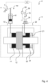
- the brake system 5 is described in detail below with respect to Figure 2 .
- the brake system 5 comprises a hydraulically actuated service brake 10.
- the service brake 10 is configured for braking the wheel loader 1.
- the service brake 10 comprises a service brake cylinder 11 and a disk pack unit 12.
- the service brake cylinder 11 is configured to transfer a service braking force to the disk pack unit 12 while braking the wheel loader 1.
- the disk pack unit 12 is configured for braking the wheel loader 1 depending on the braking force.
- the brake system 5 comprises a hydraulically actuated parking brake 20.
- the parking brake 20 is a spring applied hydraulic release brake.
- the spring applied hydraulic release brake is configured for braking the wheel loader 1 depending on a parking brake force.
- the parking brake 20 comprises a spring braking unit 21, a hydraulic park braking control unit 23, and a parking brake cylinder 22.
- the control unit 6 is signalling coupled to a control valve 24.
- the control valve 24 is hydraulically connected to the parking brake 20 and configured for controlling a hydraulic pressure inside of the parking brake 20.
- the hydraulic pressure inside of the parking brake 20 is controlled depending on a braking signal for hydraulically actuating and/or releasing the parking brake 20.
- the control valve 24 is a proportional 3/2 directional valve with a spring reset.
- the control valve 24 controls the hydraulic flow into the parking brake 20 for releasing the parking brake 20 and out of the parking brake 20 for braking the parking brake 20 depending on the braking signal detected by a sensor unit 4.
- the sensor unit 4 is adapted for detecting the braking signal for braking the wheel loader 1.
- the sensor unit 4 may comprise different kind of sensors that are adapted to detect a respective braking signal.
- the sensor unit may comprise an angle sensor, a position sensor, and/or a hydraulic pressure sensor.
- the sensor unit 4 comprises an angle sensor that is configured for detecting an angle of a braking pedal 7.
- the service brake 10 comprises a hydraulic service braking control unit 40 that is configured to generate the service braking force and to transfer the service braking force to the service brake cylinder 11.
- the hydraulic service braking control unit 40 comprises a master brake cylinder 41 that is hydraulically connected to the service brake cylinder 11 for generating the service braking force. It is to be understood that the parking brake 20 is actuated depending on an opening pressure and the service brake 10 is actuated depending on an actuation pressure.
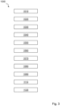
- Figures 3 and 4 are schematic block diagrams of preferred embodiments of the method 1000 for controlling a speed of the wheel loader 1 shown in Figure 1 depending on a determined actual driving condition of the wheel loader.
- the steps of both embodiments are performed in the order as described in the following. It may be preferred that some or all of the steps are executed in parallel if possible. Additional or alternative preferred embodiments of the method 1000 may execute some or all of the steps in an order that is different to the order as described herein below.
- the method 1000 comprises six steps 1010, 1020, 1030, 1040, 1050, 1060.
- a first step of the method 1000 relates to determining 1010 the actual speed value of the wheel loader 1 provided by means of the sensor unit 4.
- the method comprises the steps of determining 1020 a maximum speed value and determining a critical speed value, wherein the critical speed value is larger than the maximum speed value, and determining 1030 the actual driving condition of the wheel loader 1.
- the driving condition is at least one of the following: an overspeed driving condition, an acceleration driving condition, and a regular driving condition.
- the driving condition is considered as over speed driving condition if the determined actual speed value is larger than the determined maximum speed value and smaller than the determined critical speed value.
- the acceleration driving condition is considered as driving condition if the wheel loader 1 is accelerated and the determined actual speed value is smaller than the determined maximum speed value.
- the regular driving condition is considered as driving condition if the wheel loader 1 is not accelerated and the determined actual speed value is smaller than the determined maximum speed value.
- the method comprises the step of determining 1040 a target speed value of the wheel loader 1 that is smaller than the determined maximum speed value. Determining 1040 the target speed value depends on at least one of the following:
- the method 1000 comprises the steps of determining 1050 a speed braking signal value for actuating the friction braking unit depending on the determined target speed value, and of providing 1060 the speed braking signal value to the brake system 5 for actuating the friction braking unit if the driving condition is determined as the over speed driving condition.
- the method 1000 comprises the steps of determining 1110 a maximum braking duration value that is larger than the determined target braking duration value and counting 1120 the number of braking operations due to over speed driving events.
Landscapes
- Engineering & Computer Science (AREA)
- Transportation (AREA)
- Mechanical Engineering (AREA)
- Chemical & Material Sciences (AREA)
- Combustion & Propulsion (AREA)
- Automation & Control Theory (AREA)
- Physics & Mathematics (AREA)
- Mathematical Physics (AREA)
- Regulating Braking Force (AREA)
Abstract
Description
- The invention relates to a method and a control unit for controlling a speed of a vehicle depending on a determined actual driving condition of the vehicle. Further, the invention relates to a computer program product, a non-transitory computer-readable storage medium, brake system and a vehicle.
- From CN 113 561 794 A a driving control method and a device for a dual-motor pure electric loader is known. The method and the device include determining the driving mode and the motor control mode of a vehicle according to the current state and operation signals of the vehicle, calculating a target torque or a target rotating speed according to the opening degree of an accelerator pedal in different driving modes, and outputting the target torque or the target rotating speed as a reference rotating speed or a reference torque to a driving motor controller.
-
US 2021/0370913 A1 relates to a method for reinforcing safety of a vehicle on a ramp, which prevents a vehicle from skidding and being turned off when the vehicle starts on a reverse steep slope without applying an electrical parking brake and a vehicle thereof. In one embodiment,US 2021/0370913 A1 teaches to provide a lower and upper limit vehicle speed threshold, which may be understood as maximum and critical speed value according to the invention. According toUS 2021/0370913 A1 , the vehicle is in a primary vehicle speed condition when the speed is between the lower and upper limit vehicle speed threshold. -
EP 3 719 355 A1EP 3 719 355 A1 - These known solutions comprise several disadvantageous.
- In particular, it is known that an electric compact wheel loader accelerates in downhill conditions, if the electric motor cannot provide a sufficient brake torque. This happens for example, if lower voltage systems are used. Consequently, on the one hand, physical limits of the transmission can be exceeded and, on the other hand, the friction brake may be overheated, which can lead to dangerous situations. This can lead in particular to failure during braking and, in the worst case, not only to fender benders or alike but also to personal damage.
- An object of the invention is to provide a method and a control unit for controlling a speed of a vehicle depending on a determined actual driving condition of the vehicle as well as a computer program product, a non-transitory computer-readable storage medium, brake system and a vehicle to overcome the disadvantages outlined above. In particular, an object of the invention is to provide a method, a control unit, a computer program product, a non-transitory computer-readable storage medium, brake system and a vehicle that provides an increased braking safety.
- According to a first aspect of the invention, the object is achieved by a method according to
claim 1. The method is configured for controlling a speed of a vehicle depending on a determined actual driving condition of the vehicle. - Preferably, the vehicle is a working machine, for example a wheel loader.
- Such a vehicle comprises a drive unit. The drive unit is coupled to at least one wheel of the vehicle. Preferably, the drive unit is coupled to each wheel of the vehicle. Alternatively, it may be preferred that the vehicle comprises a drive unit for each wheel. In particular, it may be preferred that the vehicle comprises at least two drive units, wherein each drive unit is coupled to at least two wheels of the vehicle. Preferably, the drive units is directly coupled to a wheel of the vehicle. However, it may also be preferred that the drive unit or the drive units are coupled to a wheel or coupled to several wheels via a gear box or alike.
- The drive unit is configured for driving and braking the at least one wheel of the vehicle. In particular, by means of the drive unit, the vehicle is accelerated to a desired speed and/or driven with a desired speed. Further preferably, the vehicle is braked or deaccelerated by means of the drive unit. In the later case, the drive units is to be understood as some kind of motor brake.
- Preferably, the drive unit is or comprises an electric motor. The electric motor may be a direct current drive or an asynchronous drive. Alternatively or additionally, the drive unit is or comprises a hydrostatic drive unit.
- Further, the vehicle comprises a sensor unit. The sensor unit is configured for detecting an actual speed value of the vehicle. The sensor unit may detect the speed by measuring the rotational speed of one or more wheels. Additionally or alternatively, the sensor unit may detect the speed by measuring the rotational speed of the drive unit. It may also be preferred to measure the speed by means of global navigation satellite system.
- In particular, the sensor unit is or comprises a speed sensor.
- Preferably, the sensor unit is based on a potentiometer, an optical encoder, a hall sensor, an inductive encoder, a reed sensor or alike. Alternatively or additionally, the sensor unit may be based on a global navigation satellite system.
- Further, the vehicle has some kind of brake system. The brake system is coupled to the at least one wheel of the vehicle. The brake system is configured for braking the at least one wheel of the vehicle. Thus, the brake system enables to decelerate the vehicle if needed. Preferably, the brake system is some kind of mechanical brake. In particular, the brake system is or comprises a friction brake unit. Usually, in preferred embodiments the brake system comprises a service brake and/or a parking brake. Preferably, the brake system comprises a disk brake and/or a drum brake.
- Finally, the vehicle comprises a control unit. In particular, the vehicle comprises a control unit as described herein. The control unit is configured for controlling the speed of the vehicle depending on the actual driving condition of the vehicle. For this purpose, the control unit is signalling coupled with the sensor unit, the drive unit, and the brake system. It may be preferred that the control unit is signalling coupled to some or all device via a wire or wirelessly.
- For controlling the speed of the vehicle depending on the actual driving condition of the vehicle, the method comprises several steps. These steps of the method will be elaborated in the following.
- The method comprises the step of determining the actual speed value of the vehicle. The actual speed value of the vehicle is determined by means of the sensor unit. Further, the method comprises the step of determining a maximum speed value and determining a critical speed value. The maximum speed value and/or the critical speed value may be determined by the user and/or the manufacturer and/or the seller of the vehicle. In particular, the maximum speed value and/or the critical speed value depends on the drive unit the vehicle comprises. Preferably, the maximum speed value and/or the critical speed value depends on the performance data of the drive unit.
- It is to be understood that the critical speed value is defined to be larger than the maximum speed value. Depending on the determined critical speed value and the determined maximum speed value the speed of the vehicle is controlled as will be described in the following.
- According to a further step of the method, the actual driving condition is determined. Determining the driving condition depends on the determined actual speed value of the vehicle as well as the determined maximum speed value and the determined critical speed value. Accordingly, the driving condition is at least one of the following: an over speed driving condition, an acceleration driving condition or a regular driving condition. The over speed driving condition exists if the determined actual speed value is larger than the determined maximum speed value and smaller than the determined critical speed value. The acceleration driving condition exists if the vehicle is accelerated and the determined actual speed value is smaller than the determined maximum speed value. Finally, the regular driving condition exists if the vehicle is not accelerated and the determined actual speed value is smaller than the determined maximum speed value.
- The method further comprises the step of determining a target speed value of the vehicle that is smaller than the determined maximum speed value. Depending on the determined a target speed value, the method further comprises following two steps if the driving condition is determined as the over speed driving condition: determining a speed braking signal value for actuating the friction braking unit depending on the determined target speed value, and providing the speed braking signal value to the brake system for actuating the friction braking unit.
- If an acceleration of the machine, deviating from maximum requested speed, is being detected, the machine speed can be automatically reduced via actuation of the friction brake. By using the friction brake only for a short time, an overheating of the friction brake can be prevented. Overheating can lead to fading and can cause thermal damages.
- As to further advantages, preferred embodiments and details of the method, reference is made to the corresponding aspects and embodiments of the control unit, the computer program product, the non-transitory computer-readable storage medium, the brake system and the vehicle described herein below.
- According to a preferred embodiment of the method, it is provided that the method comprises further steps. In particular, the method comprises the step of determining a target braking duration value. The target braking duration value is the value a braking duration of the vehicle should last. Hereby, the target braking duration value is to be determined in such a manner that the brake system, in particular the friction brake, does not overheat. The longer a braking procedure lasts the higher the risk of degeneration of the brake system. Thus, the target braking duration value is to be determined in such a manner that the brake system does not overheat. It is to be understood that the target braking duration value may vary depending on the type of brake system. For example if the brake system comprises relatively large disk brakes, the target braking duration value may be larger in comparison to a target braking duration value of a brake system having smaller disk brakes. Further, the target braking duration value may also decrease over time if the brake system is regularly used over a longer period of time as the brake system is not able to cool down sufficiently.
- Additionally or alternatively, the method comprises the step of determining a target deceleration value of the vehicle. Similarly to the target braking duration value the target deceleration value depends on the type of brake system used. If the brake system comprises relatively large disk brakes, the target deceleration value may be larger in comparison to a brake system with smaller disk brakes. Also, the target deceleration value decreases over time if the brake system is regularly used over a longer period of time as the brake system is not able to cool down sufficiently.
- Further, additionally or alternatively, the method comprises the step of determining the speed braking signal value for actuating the friction braking unit depends on the determined target braking duration value and/or the determined target deceleration value.
- By considering the target braking duration value and/or the determined target deceleration value it decreases the risk of overheating of the brake system. In particular, controlling and efficiency of the braking of the brake system is improved.
- In a further preferred embodiment, the method comprises further steps. It is provided that the method comprises the step of determining a minimum braking resting duration of the friction braking unit between a prior first braking operation due to a prior first over speed driving event and a subsequent second braking operation due to a subsequent second over speed driving event, and determining an actual braking resting duration between the prior first braking operation due to the prior first over speed driving event and the subsequent second braking operation due to the subsequent second over speed driving event, wherein the speed braking signal value for actuating the friction braking unit is only provided for actuating the friction braking unit if the determined actual braking resting duration exceeds the determined minimum braking resting duration of the friction braking unit.
- By determining the minimum braking resting duration it is assured that the brake system has sufficient time to cool down to ensure safe braking of the vehicle. Further, by tracking the actual braking resting duration time, controlling and efficiency of the braking of the brake system may be improved as braking resting duration that may be too short for cooling down or longer braking resting duration that allow to cool down the braking system more than necessary for safety reasons can be considered.
- In another preferred embodiment the method comprises the step of determining a maximum braking duration value that is larger than the determined target braking duration value.
- Further, to prevent degeneration and overheating of the brake system, a braking procedure of the vehicle should not exceed the maximum braking duration value. Otherwise, the brake system overheats and degenerates.
- Yet in a further preferred embodiment, the method comprises the step of counting the number of braking operations due to over speed driving events.
- By considering the number of braking operations due to over speed drive events, durability of the brake system can be better estimated. In particular, this allows to better control the brake system with respect to the parameters introduced above.
- Further in a preferred embodiment of the method it is provided that determining the minimum braking resting duration depends on at least one of the following:
- an actual weight of the vehicle,
- the determined actual speed value,
- the determined target speed value of the prior first braking operation,
- the determined target braking duration value of the prior first braking operation,
- the determined target deceleration value of the prior first braking operation,
- the counted number of braking operations due to prior over speed driving events, and
- the target speed value to be determined for the subsequent second braking operation.
- According to another preferred embodiment of the method, determining the target speed value depends on at least one of the following:
- an actual weight of the vehicle,
- the determined actual speed value,
- the determined target speed value of the prior first braking operation,
- the determined target braking duration value of the prior first braking operation,
- the determined target deceleration value of the prior first braking operation,
- the counted number of braking operations due to prior over speed driving events,
- the target speed value to be determined for the subsequent second braking operation, and
- the time between a prior first over speed driving condition and a subsequent second over speed driving condition.
- Further, in a preferred embodiment of the method the brake system comprises a service brake, in particular a friction brake, and/or a parking brake, in particular a spring applied hydraulically released brake unit. Preferably, the method comprises the step of releasing the hydraulic pressure in the spring applied hydraulically released brake unit depending on the speed braking signal value provided to the brake system, in particular below a spring braking force of the spring of the spring applied hydraulically released brake unit.
- According to a further aspect of the invention, the object is achieved by a control unit according to claim 9. The control unit is configured for controlling a speed of a vehicle, in particular of a working machine such as a wheel loader, depending on an actual driving condition of the vehicle. Further, the control unit is configured to perform the method according to the aspect and its embodiments of the method described herein above.
- As to the advantages, preferred embodiments and details of the control unit, reference is made to the corresponding aspects and embodiments of the method and/or the computer program product and/or the non-transitory computer-readable storage medium and/or the brake system and/or the vehicle described herein above and/or below.
- According to a further aspect of the invention, the object is achieved by a computer program product according to
claim 10. The computer program product comprising program code for performing, when executed by the control unit, the method according to the aspect and its embodiments of the method described herein above and/or below. - As to the advantages, preferred embodiments and details of the computer program product, reference is made to the corresponding aspects and embodiments of the method and/or the control unit and/or the non-transitory computer-readable storage medium and/or the brake system and/or the vehicle described herein above and/or below.
- According to a further aspect of the invention, the object is achieved by a non-transitory computer-readable storage medium according to
claim 11. The non-transitory computer-readable storage medium comprising instructions, which when executed by the control unit, cause the control unit to perform the method according to the aspect and its embodiments of the method described herein above. - As to the advantages, preferred embodiments and details of the non-transitory computer-readable storage medium, reference is made to the corresponding aspects and embodiments of the method and/or the control unit and/or the computer program product and/or the brake system and/or the vehicle described herein above and/or below.
- According to a further aspect of the invention, the object is achieved by a brake system according to
claim 12. The brake system is configured for braking at least one wheel of a vehicle, the brake system comprising a control unit of the aspect and its embodiments of the control unit described herein above. - As to the advantages, preferred embodiments and details of the brake system, reference is made to the corresponding aspects and embodiments of the method and/or the control unit and/or the computer program product and/or the non-transitory computer readable storage medium and/or the vehicle described herein above and/or below.
- According to a further aspect of the invention, the object is achieved by a vehicle according to claim 13. In particular, the vehicle is a working machine such as a wheel loader.
- The vehicle comprises a drive unit that is coupled to at least one wheel of the vehicle, wherein the drive unit is configured for driving and braking the at least one wheel of the vehicle, and a sensor unit that is configured for detecting actual speed value of the vehicle, and a brake system that is coupled to at least one wheel of the vehicle, wherein the brake system is configured for braking the at least one wheel of the vehicle, and a control unit according to claim # that is signalling coupled with the sensor unit, the drive unit, and the brake system, wherein the control unit is configured for controlling the speed of the vehicle depending on an actual driving condition of the vehicle, wherein the driving condition is one of the following: an over speed driving condition, in which the determined actual speed value is largerthan the determined maximum speed value and smallerthan the determined critical speed value, an acceleration driving condition, in which the vehicle is accelerated and the determined actual speed value is smaller than the determined maximum speed value, and a regular driving condition, in which the vehicle is not accelerated and the determined actual speed value is smaller than the determined maximum speed value.
- As to the advantages, preferred embodiments and details of the vehicle, reference is made to the corresponding aspects and embodiments of the method and/or the control unit and/or the computer program product and/or the non-transitory computer readable storage medium and/or the brake system described herein above.
- According to a preferred embodiment of the vehicle, the drive unit is or comprises an electric drive unit and/or is or comprises a hydrostatic drive unit. Additionally or alternatively, the brake system comprises a service brake, in particular a friction brake, and/or a parking brake, in particular a spring applied hydraulically re-leased brake unit.
- In a further preferred embodiment, of the vehicle the sensor unit is or comprises at least one sensor that is configured for detecting the actual speed of the vehicle, and/or at least one sensor that is configured for detecting an actual acceleration of the vehicle, and/or at least one sensor that is configured for detecting an actual inclination of the vehicle, and/or at least one GNSS-sensor, and/or at least one sensor that is configured for detecting an actuation of a braking pedal, for example an angle sensor.
- Embodiments of the invention are now described below with reference to the drawings. These are not necessarily intended to show the embodiments to scale; rather, where useful for explanation, the drawings are in schematized and/or slightly distorted form. With regard to additions to the gauges directly recognizable from the drawings, reference is made to the relevant prior art. It should be borne in mind that a wide variety of modifications and changes concerning the shape and detail of an embodiment can be made without departing from the general idea of the invention. The features of the invention disclosed in the description, in the drawings as well as in the claims may be essential for the further development of the invention both individually and in any combination. In addition, all combinations of at least two of the features disclosed in the description, the drawings and/or the claims fall within the scope of the invention. The general idea of the invention is not limited to the exact form or detail of the preferred embodiments shown and described below, or limited to any subject matter that would be limited as compared to the subject matter claimed in the claims. In the case of stated design ranges, values lying within the stated limits are also intended to be disclosed as limiting values and to be capable of being used and claimed as desired. For simplicity, identical reference signs are used below for identical or similar parts or parts with identical or similar function.
- Further advantages and advantageous features of the invention are disclosed in the following description and in the dependent claims.
- With reference to the appended drawings, below follows a more detailed description of embodiments of the invention cited as examples.
- In the drawings:
- Figure 1
- is a schematic side view of a wheel loader in a preferred embodiment;
- Figure 2
- is schematic view a preferred embodiment of the brake system for controlling a speed of the wheel loader shown in
Figure 1 according to one of the methods illustrated inFigures 3 and4 - Figure 3
- is a schematic block diagram of a preferred embodiment of the method for controlling a speed of the wheel loader shown in
Figure 1 depending on a determined actual driving condition of the wheel loader; and - Figure 4
- is a schematic block diagram of a further preferred embodiment of the method for controlling a speed of the wheel loader shown in
Figure 1 depending on a determined actual driving condition of the wheel loader. -
Figure 1 is a schematic side view of a wheel loader as avehicle 1 in a preferred embodiment. - The
wheel loader 1 shown inFigure 1 comprise fourdrive units 2 each of which is coupled to asingle wheel 3 of thewheel loader 1. By means of thedrive units 2 thewheel loader 1 is accelerated to a desired speed or run with a desired speed. Thus, thedrive units 2 enable driving thewheel loader 1 by driving therespective wheels 3. Further, thedrive units 2 are configured for braking therespective wheel 3 and, thus, thewheel loader 1. Thus, the drive units also enable deceleration of the wheels and, thus, thewheel loader 1. In this preferred embodiment, thedrive units 2 are electric drive units. However, it is possible as well that thedrive units 2 are hydrostatic drive units. - Further, for controlling the speed of the
wheel loader 1 depending on an actual driving condition of thewheel loader 1, thewheel loader 1 comprises asensor unit 4, abrake system 5 and acontrol unit 6. - The
sensor unit 4 is configured for detecting actual speed value of thewheel loader 1. In this preferred embodiment, thesensor unit 4 comprises sensors that are configured for detecting the actual speed, for detecting an actual acceleration, and for detecting an actual inclination of the wheel loader as well as a sensor that is configured for detecting an actuation of thebrake system 5. - The
brake system 5 is coupled to eachwheel 3 of thewheel loader 1. Thebrake system 5 is configured for braking eachwheel 3 of the vehicle. In this preferred embodiment, the brake system comprises a friction brake as service brake and a spring applied hydraulically released brake unit as parking brake. This particular embodiment of thebrake system 5 allows to prevent overheating in a particular preferred manner. Thebrake system 5 is described in detail below with respect toFigure 2 . - The
control unit 6 is signalling coupled to eachdrive unit 2, thesensor unit 4 and thebrake system 5 of thewheel loader 1. Thecontrol unit 6 is configured for controlling the speed of thewheel loader 1 depending on an actual driving condition of thewheel loader 1. Thereby, the actual driving condition of thewheel loader 1 is one of the following: - an over speed driving condition, in which the determined actual speed value is largerthan the determined maximum speed value and smallerthan the determined critical speed value,
- an acceleration driving condition, in which the
wheel loader 1 is accelerated and the determined actual speed value is smaller than the determined maximum speed value, and - a regular driving condition, in which the
wheel loader 1 is not accelerated and the determined actual speed value is smaller than the determined maximum speed value. -
Figure 2 is schematic view of a preferred embodiment of thebrake system 5 for controlling the speed of thewheel loader 1 shown inFigure 1 according to one of the embodiments of the method schematically illustrated as block diagrams inFigures 3 and4 . - The
brake system 5 comprises a hydraulically actuatedservice brake 10. Theservice brake 10 is configured for braking thewheel loader 1. For this purpose, theservice brake 10 comprises aservice brake cylinder 11 and adisk pack unit 12. Theservice brake cylinder 11 is configured to transfer a service braking force to thedisk pack unit 12 while braking thewheel loader 1. Thedisk pack unit 12 is configured for braking thewheel loader 1 depending on the braking force. - Furthermore, the
brake system 5 comprises a hydraulically actuatedparking brake 20. Theparking brake 20 is a spring applied hydraulic release brake. The spring applied hydraulic release brake is configured for braking thewheel loader 1 depending on a parking brake force. Forthis purpose, theparking brake 20 comprises aspring braking unit 21, a hydraulic park braking control unit 23, and aparking brake cylinder 22. - The
spring braking unit 21 is configured to generate a default parking brake force and to transfer the default parking brake force onto aparking brake cylinder 22. Thecontrol unit 6 is configured to generate a release force and to transfer the release force onto theparking brake cylinder 22 in order to control the parking brake force. Finally, theparking brake cylinder 22 is in mechanical contact with thedisk pack unit 12. Thereby, theparking brake cylinder 22 is configured to transfer the parking braking force to thedisk pack unit 12 while braking depending on the control parking brake force and the default parking brake force. - The
control unit 6 is signalling coupled to acontrol valve 24. Thecontrol valve 24 is hydraulically connected to theparking brake 20 and configured for controlling a hydraulic pressure inside of theparking brake 20. The hydraulic pressure inside of theparking brake 20 is controlled depending on a braking signal for hydraulically actuating and/or releasing theparking brake 20. In this preferred embodiment, thecontrol valve 24 is a proportional 3/2 directional valve with a spring reset. Thecontrol valve 24 controls the hydraulic flow into theparking brake 20 for releasing theparking brake 20 and out of theparking brake 20 for braking theparking brake 20 depending on the braking signal detected by asensor unit 4. Thesensor unit 4 is adapted for detecting the braking signal for braking thewheel loader 1. Hereto, thesensor unit 4 may comprise different kind of sensors that are adapted to detect a respective braking signal. For example, the sensor unit may comprise an angle sensor, a position sensor, and/or a hydraulic pressure sensor. In this preferred embodiment, thesensor unit 4 comprises an angle sensor that is configured for detecting an angle of abraking pedal 7. - For controlling the braking of the
wheel loader 1, theservice brake 10 comprises a hydraulic servicebraking control unit 40 that is configured to generate the service braking force and to transfer the service braking force to theservice brake cylinder 11. In this preferred embodiment, the hydraulic servicebraking control unit 40 comprises amaster brake cylinder 41 that is hydraulically connected to theservice brake cylinder 11 for generating the service braking force. It is to be understood that theparking brake 20 is actuated depending on an opening pressure and theservice brake 10 is actuated depending on an actuation pressure. -
Figures 3 and4 are schematic block diagrams of preferred embodiments of themethod 1000 for controlling a speed of thewheel loader 1 shown inFigure 1 depending on a determined actual driving condition of the wheel loader. Preferably, the steps of both embodiments are performed in the order as described in the following. It may be preferred that some or all of the steps are executed in parallel if possible. Additional or alternative preferred embodiments of themethod 1000 may execute some or all of the steps in an order that is different to the order as described herein below. - In
Figure 3 , themethod 1000 comprises sixsteps - A first step of the
method 1000 relates to determining 1010 the actual speed value of thewheel loader 1 provided by means of thesensor unit 4. - Subsequently, the method comprises the steps of determining 1020 a maximum speed value and determining a critical speed value, wherein the critical speed value is larger than the maximum speed value, and determining 1030 the actual driving condition of the
wheel loader 1. Thereby, the driving condition is at least one of the following: an overspeed driving condition, an acceleration driving condition, and a regular driving condition. The driving condition is considered as over speed driving condition if the determined actual speed value is larger than the determined maximum speed value and smaller than the determined critical speed value. The acceleration driving condition is considered as driving condition if thewheel loader 1 is accelerated and the determined actual speed value is smaller than the determined maximum speed value. Finally, the regular driving condition is considered as driving condition if thewheel loader 1 is not accelerated and the determined actual speed value is smaller than the determined maximum speed value. - Next, the method comprises the step of determining 1040 a target speed value of the
wheel loader 1 that is smaller than the determined maximum speed value. Determining 1040 the target speed value depends on at least one of the following: - an actual weight of the
wheel loader 1, - the determined actual speed value,
- the determined target speed value of the prior first braking operation,
- the determined target braking duration value of the prior first braking operation,
- the determined target deceleration value of the prior first braking operation,
- the counted number of braking operations due to prior over speed driving events,
- the target speed value to be determined for the subsequent second braking operation, and
- the time between a prior first over speed driving condition and a subsequent second over speed driving condition.
- Finally, the
method 1000 comprises the steps of determining 1050 a speed braking signal value for actuating the friction braking unit depending on the determined target speed value, and of providing 1060 the speed braking signal value to thebrake system 5 for actuating the friction braking unit if the driving condition is determined as the over speed driving condition. - The preferred embodiment of the
method 1000 schematically depicted as block diagram inFigure 4 is based on the method described with respect toFigure 3 . The embodiment referred to inFigure 4 comprises five additional steps in comparison to the embodiment described herein above with respect toFigure 4 . - The
method 1000 comprises the steps of determining 1070 a target braking duration value, and determining 1080 a target deceleration value of the wheel loader. It is to be understood that the step of determining 1050 a speed braking signal value for actuating the friction braking unit additionally depends on determined target braking duration value and the determined target deceleration value. - Further, the
method 1000 comprises the steps of determining 1090 a minimum braking resting duration of the friction braking unit between a prior first braking operation due to a prior first over speed driving event and a subsequent second braking operation due to a subsequent second over speed driving event, and determining 1100 an actual braking resting duration between the prior first braking operation due to the prior first over speed driving event and the subsequent second braking operation due to the subsequent second over speed driving event. Thereby, the speed braking signal value for actuating the friction braking unit is only provided for actuating the friction braking unit if the determined actual braking resting duration exceeds the determined minimum braking resting duration of the friction braking unit. - Finally, the
method 1000 comprises the steps of determining 1110 a maximum braking duration value that is larger than the determined target braking duration value and counting 1120 the number of braking operations due to over speed driving events. - It is to be understood that determining 1090 the minimum braking resting duration depends on at least one of the following:
- an actual weight of the
wheel loader 1, - the determined actual speed value,
- the determined target speed value of the prior first braking operation,
- the determined target braking duration value of the prior first braking operation,
- the determined target deceleration value of the prior first braking operation,
- the counted number of braking operations due to prior over speed driving events, and
- the target speed value to be determined for the subsequent second braking operation.
- In case the
brake system 5 comprises a friction brake as service brake and a spring applied hydraulically released brake unit as parking brake, it is to be understood that the method comprises the step of releasing the hydraulic pressure in the spring applied hydraulically released brake unit depending on the speed braking signal value provided to thebrake system 5, in particular below a spring braking force of the spring of the spring applied hydraulically released brake unit. -
- 1
- vehicle
- 2
- drive unit
- 3
- wheel
- 4
- sensor unit
- 5
- brake system
- 6
- control unit
- 7
- braking pedal
- 10
- service brake
- 11
- service brake cylinder
- 12
- disk pack unit
- 20
- parking brake
- 21
- spring braking unit
- 22
- parking brake cylinder
- 24
- control valve
- 41
- master brake cylinder
- 50
- hydraulic pump
- 60
- hydraulic accumulator
- 70
- check valve
Claims (15)
- A method (1000) for controlling a speed of a vehicle (1), in particular of a working machine such as a wheel loader (1), depending on a determined actual driving condition of the vehicle (1),the vehicle (1) comprising:- a drive unit (2) that is coupled to at least one wheel (3) of the vehicle (1), wherein the drive unit (2) is configured for driving and braking the at least one wheel (3) of the vehicle (1), wherein the drive unit (2) is configured for braking by providing a motor braking torque, and- a sensor unit (4) that is configured for detecting an actual speed value of the vehicle (1), and- a brake system (5) that is coupled to at least one wheel (3) of the vehicle (1), wherein the brake system (5) is configured for braking the at least one wheel (3) of the vehicle (1), and- a control unit (6) that is signalling coupled with the sensor unit (4), the drive unit (2), and the brake system (5), wherein the control unit (6) is configured for controlling the speed of the vehicle (1),the method (1000) comprising the steps:- determining (1010) the actual speed value of the vehicle (1) provided by means of the sensor unit (4), and- determining (1020) a maximum speed value and determining a critical speed value, wherein the critical speed value is larger than the maximum speed value, and- determining (1030) the actual driving condition of the vehicle (1), wherein the driving condition is at least one of the following:∘ an over speed driving condition if the determined actual speed value is larger than the determined maximum speed value and smaller than the determined critical speed value,∘ an acceleration driving condition if the vehicle (1) is accelerated and the determined actual speed value is smaller than the determined maximum speed value,∘ a regular driving condition if the vehicle (1) is not accelerated and the determined actual speed value is smaller than the determined maximum speed value,- determining (1040) a target speed value of the vehicle (1) that is smaller than the determined maximum speed value, and- wherein if the driving condition is determined as the over speed driving condition, the method (1000) comprising the steps of∘ determining (1050) a speed braking signal value for actuating the friction braking unit depending on the determined target speed value, and∘ providing (1060) the speed braking signal value to the brake system (5) for actuating the friction braking unit.
- The method (1000) according to claim 1,- determining (1070) a target braking duration value, and/or- determining (1080) a target deceleration value of the vehicle (1), and/or- determining (1050) the speed braking signal value for actuating the friction braking unit depends on the determined target braking duration value and/or the determined target deceleration value.
- The method (1000) according to any claims 1-2, comprising the steps:- determining (1090) a minimum braking resting duration of the friction braking unit between a prior first braking operation due to a prior first overspeed driving event and a subsequent second braking operation due to a subsequent second over speed driving event, and- determining (1100) an actual braking resting duration between the prior first braking operation due to the prior first over speed driving event and the subsequent second braking operation due to the subsequent second over speed driving event, wherein- the speed braking signal value for actuating the friction braking unit is only provided for actuating the friction braking unit if the determined actual braking resting duration exceeds the determined minimum braking resting duration of the friction braking unit.
- The method (1000) according to any claims 1-3, comprising the step:- determining (1110) a maximum braking duration value that is larger than the determined target braking duration value.
- The method (1000) according to any claims 1-4, comprising the step:- counting (1120) the number of braking operations due to over speed driving events.
- The method (1000) according to any claims 1-5, wherein determining (1090) the minimum braking resting duration depends on at least one of the following:- an actual weight of the vehicle (1),- the determined actual speed value,- the determined target speed value of the prior first braking operation,- the determined target braking duration value of the prior first braking operation,- the determined target deceleration value of the prior first braking operation,- the counted number of braking operations due to prior over speed driving events, and- the target speed value to be determined for the subsequent second braking operation.
- The method (1000) according to any claims 1-6, wherein determining (1040) the target speed value depends on at least one of the following:- an actual weight of the vehicle (1),- the determined actual speed value,- the determined target speed value of the prior first braking operation,- the determined target braking duration value of the prior first braking operation,- the determined target deceleration value of the prior first braking operation,- the counted number of braking operations due to prior over speed driving events,- the target speed value to be determined for the subsequent second braking operation, and- the time between a prior first over speed driving condition and a subsequent second over speed driving condition.
- The method (1000) according to any claims 1-7,- wherein the brake system (5) comprises a service brake (10), in particular a friction brake, and/or a parking brake (20), in particular a spring applied hydraulically released brake unit,- wherein preferably, the method comprises the step of releasing the hydraulic pressure in the spring applied hydraulically released brake unit depending on the speed braking signal value provided to the brake system (5), in particular below a spring braking force of the spring of the spring applied hydraulically released brake unit.
- A control unit (6) for controlling a speed of a vehicle (1), in particular of a working machine such as a wheel loader (1), depending on an actual driving condition of the vehicle (1), wherein the control unit (6) is configured to perform the method (1000) of any of claims 1-7.
- A computer program product comprising program code for performing, when executed by the control unit (6), the method (1000) of any of claims 1-7.
- A non-transitory computer-readable storage medium comprising instructions, which when executed by the control unit (6), cause the control unit (6) to perform the method (1000) of any of claims 1-7.
- A brake system (5) for braking at least one wheel (3) of a vehicle (1), the brake system (5) comprising a control unit (6) according to claim 9.
- A vehicle (1), in particular of a working machine such as a wheel loader (1), the vehicle (1) comprising:- a drive unit (2) that is coupled to at least one wheel (3) of the vehicle (1), wherein the drive unit (2) is configured for driving and braking the at least one wheel (3) of the vehicle (1), and- a sensor unit (4) that is configured for detecting actual speed value of the vehicle (1), and- a brake system (5) that is coupled to at least one wheel (3) of the vehicle (1), wherein the brake system (5) is configured for braking the at least one wheel (3) of the vehicle (1), and- a control unit (6) according to claim 9 that is signalling coupled with the sensor unit (4), the drive unit (2), and the brake system (5), wherein the control unit (6) is configured for controlling the speed of the vehicle (1) depending on an actual driving condition of the vehicle (1), wherein the driving condition is one of the following:∘ an over speed driving condition, in which the determined actual speed value is largerthan the determined maximum speed value and smaller than the determined critical speed value,∘ an acceleration driving condition, in which the vehicle (1) is accelerated and the determined actual speed value is smaller than the determined maximum speed value, and∘ a regular driving condition, in which the vehicle (1) is not accelerated and the determined actual speed value is smaller than the determined maximum speed value.
- The vehicle (1) according to claim 13,- wherein the drive unit (2) is or comprises an electric drive unit (2) and/or is or comprises a hydrostatic drive unit (2), and/or- wherein the brake system (5) comprises a service brake, in particular a friction brake, and/or a parking brake, in particular a spring applied hydraulically re-leased brake unit.
- The vehicle (1) according to any of claims 13-14, wherein the sensor unit (4) is or comprises- at least one sensor that is configured for detecting the actual speed of the vehicle (1), and/or- at least one sensor that is configured for detecting an actual acceleration of the vehicle (1), and/or- at least one sensor that is configured for detecting an actual inclination of the vehicle (1), and/or- at least one GNSS-sensor, and/or- at least one sensor that is configured for detecting an actuation of a braking pedal, for example an angle sensor.
Priority Applications (3)
| Application Number | Priority Date | Filing Date | Title |
|---|---|---|---|
| EP23150550.4A EP4397549B1 (en) | 2023-01-06 | 2023-01-06 | Method for controlling a speed of a vehicle, control unit, computer program product, non-transitory computer readable storage medium, brake system, and vehicle |
| CN202311653894.XA CN118306406A (en) | 2023-01-06 | 2023-12-04 | Method for controlling vehicle speed, control unit, computer-readable storage medium, braking system and vehicle |
| US18/528,918 US20240227805A1 (en) | 2023-01-06 | 2023-12-05 | Method for controlling a speed of a vehicle, control unit, computer program product, non-transitory computer readable storage medium, brake system, and vehicle |
Applications Claiming Priority (1)
| Application Number | Priority Date | Filing Date | Title |
|---|---|---|---|
| EP23150550.4A EP4397549B1 (en) | 2023-01-06 | 2023-01-06 | Method for controlling a speed of a vehicle, control unit, computer program product, non-transitory computer readable storage medium, brake system, and vehicle |
Publications (2)
| Publication Number | Publication Date |
|---|---|
| EP4397549A1 true EP4397549A1 (en) | 2024-07-10 |
| EP4397549B1 EP4397549B1 (en) | 2026-02-04 |
Family
ID=84887460
Family Applications (1)
| Application Number | Title | Priority Date | Filing Date |
|---|---|---|---|
| EP23150550.4A Active EP4397549B1 (en) | 2023-01-06 | 2023-01-06 | Method for controlling a speed of a vehicle, control unit, computer program product, non-transitory computer readable storage medium, brake system, and vehicle |
Country Status (3)
| Country | Link |
|---|---|
| US (1) | US20240227805A1 (en) |
| EP (1) | EP4397549B1 (en) |
| CN (1) | CN118306406A (en) |
Citations (6)
| Publication number | Priority date | Publication date | Assignee | Title |
|---|---|---|---|---|
| US6240356B1 (en) * | 1998-12-23 | 2001-05-29 | Caterpillar Inc. | Work machine speed control system to manage engine overspeed and brake energy |
| EP1270358A2 (en) * | 2001-06-29 | 2003-01-02 | The Raymond Corporation | Method and apparatus for limiting truck speed as a function of braking |
| EP3719355A1 (en) | 2019-04-05 | 2020-10-07 | CNH Industrial Italia S.p.A. | Hydrostatic transmission for a work vehicle provided with a system for preventing engine over speed during braking or reversing downhill |
| CN111071299B (en) * | 2020-01-02 | 2021-10-08 | 中车青岛四方车辆研究所有限公司 | Overspeed protection control method for train network control system |
| CN113561794A (en) | 2021-08-05 | 2021-10-29 | 天津工程机械研究院有限公司 | Drive control method and device of dual-motor pure electric loader |
| US20210370913A1 (en) | 2020-06-02 | 2021-12-02 | Hyundai Motor Company | Method for reinforcing vehicle safety on ramp and vehicle thereof |
Family Cites Families (5)
| Publication number | Priority date | Publication date | Assignee | Title |
|---|---|---|---|---|
| US6461273B1 (en) * | 2001-06-01 | 2002-10-08 | Eaton Corporation | Automated transmission upshift brake control |
| US8401753B2 (en) * | 2009-11-23 | 2013-03-19 | Caterpillar Inc. | Automatic downhill speed control system |
| US8733489B2 (en) * | 2011-02-15 | 2014-05-27 | Deere & Company | Vehicle overspeed protection system |
| CN103814232B (en) * | 2011-09-27 | 2016-12-21 | 纳博特斯克有限公司 | Speed restraint device for vehicle and vehicle with speed restraint device |
| US10501063B2 (en) * | 2016-08-29 | 2019-12-10 | GM Global Technology Operations LLC | Brake-by-wire system |
-
2023
- 2023-01-06 EP EP23150550.4A patent/EP4397549B1/en active Active
- 2023-12-04 CN CN202311653894.XA patent/CN118306406A/en active Pending
- 2023-12-05 US US18/528,918 patent/US20240227805A1/en active Pending
Patent Citations (6)
| Publication number | Priority date | Publication date | Assignee | Title |
|---|---|---|---|---|
| US6240356B1 (en) * | 1998-12-23 | 2001-05-29 | Caterpillar Inc. | Work machine speed control system to manage engine overspeed and brake energy |
| EP1270358A2 (en) * | 2001-06-29 | 2003-01-02 | The Raymond Corporation | Method and apparatus for limiting truck speed as a function of braking |
| EP3719355A1 (en) | 2019-04-05 | 2020-10-07 | CNH Industrial Italia S.p.A. | Hydrostatic transmission for a work vehicle provided with a system for preventing engine over speed during braking or reversing downhill |
| CN111071299B (en) * | 2020-01-02 | 2021-10-08 | 中车青岛四方车辆研究所有限公司 | Overspeed protection control method for train network control system |
| US20210370913A1 (en) | 2020-06-02 | 2021-12-02 | Hyundai Motor Company | Method for reinforcing vehicle safety on ramp and vehicle thereof |
| CN113561794A (en) | 2021-08-05 | 2021-10-29 | 天津工程机械研究院有限公司 | Drive control method and device of dual-motor pure electric loader |
Also Published As
| Publication number | Publication date |
|---|---|
| EP4397549B1 (en) | 2026-02-04 |
| CN118306406A (en) | 2024-07-09 |
| US20240227805A1 (en) | 2024-07-11 |
Similar Documents
| Publication | Publication Date | Title |
|---|---|---|
| US6416140B1 (en) | Vehicle brake control apparatus for controlling normal wheel brakes upon detection of defective wheel brake or brakes | |
| US5322352A (en) | Electric vehicle regenerative and friction braking control system | |
| US6539297B2 (en) | Method and device for evaluating a sensor signal | |
| US4881784A (en) | ABS pressure apply algorithm | |
| JP5252118B2 (en) | Vehicle control device | |
| US7152935B2 (en) | Operation of a vehicle brake system in dependence upon brake surface temperatures | |
| GB2305988A (en) | A vehicle brake system with electric-motor driven brake actuators | |
| US6237729B1 (en) | Method and apparatus for controlling a vehicle braking system | |
| KR20120037478A (en) | Motor vehicle braking system having a hydraulically actuated operating braking system and an electromechanically actuated braking system | |
| US20180065629A1 (en) | System and method for controlling a vehicle | |
| JPH08207728A (en) | Electronic control method and apparatus for vehicle brake system | |
| JP2005535513A (en) | Integral brake device for motorcycles | |
| JPH0443829B2 (en) | ||
| JPH0790764B2 (en) | Wheel lock control device | |
| KR20210065717A (en) | Electronic parking brake system and control method thereof | |
| JP2000351347A (en) | Brake light control device | |
| CN107031586A (en) | Brakes for the method for the brakes that operates motor vehicles and for motor vehicles | |
| KR101485518B1 (en) | Engaging position memorizing device and brake system using the same | |
| JP2001080496A (en) | Electric brake device | |
| US11273823B2 (en) | Method for determining a maximum speed of a vehicle during a parking maneuver | |
| CN110072745B (en) | Method and device for operating a motor vehicle, motor vehicle | |
| JP6134385B2 (en) | Brake control device for vehicle and method for operating at least one electric drive motor for vehicle | |
| CN1535860B (en) | Braking system for electric industry truck | |
| GB2366341A (en) | Improving rapid reversal of an electric motor driven brake actuator having a brake lock | |
| EP4397549B1 (en) | Method for controlling a speed of a vehicle, control unit, computer program product, non-transitory computer readable storage medium, brake system, and vehicle |
Legal Events
| Date | Code | Title | Description |
|---|---|---|---|
| PUAI | Public reference made under article 153(3) epc to a published international application that has entered the european phase |
Free format text: ORIGINAL CODE: 0009012 |
|
| STAA | Information on the status of an ep patent application or granted ep patent |
Free format text: STATUS: REQUEST FOR EXAMINATION WAS MADE |
|
| 17P | Request for examination filed |
Effective date: 20240216 |
|
| AK | Designated contracting states |
Kind code of ref document: A1 Designated state(s): AL AT BE BG CH CY CZ DE DK EE ES FI FR GB GR HR HU IE IS IT LI LT LU LV MC ME MK MT NL NO PL PT RO RS SE SI SK SM TR |
|
| RIC1 | Information provided on ipc code assigned before grant |
Ipc: B60T 7/12 20060101AFI20250616BHEP Ipc: B60W 30/14 20060101ALI20250616BHEP |
|
| GRAP | Despatch of communication of intention to grant a patent |
Free format text: ORIGINAL CODE: EPIDOSNIGR1 |
|
| STAA | Information on the status of an ep patent application or granted ep patent |
Free format text: STATUS: GRANT OF PATENT IS INTENDED |
|
| INTG | Intention to grant announced |
Effective date: 20250905 |
|
| GRAS | Grant fee paid |
Free format text: ORIGINAL CODE: EPIDOSNIGR3 |
|
| GRAA | (expected) grant |
Free format text: ORIGINAL CODE: 0009210 |
|
| STAA | Information on the status of an ep patent application or granted ep patent |
Free format text: STATUS: THE PATENT HAS BEEN GRANTED |
|
| AK | Designated contracting states |
Kind code of ref document: B1 Designated state(s): AL AT BE BG CH CY CZ DE DK EE ES FI FR GB GR HR HU IE IS IT LI LT LU LV MC ME MK MT NL NO PL PT RO RS SE SI SK SM TR |
|
| REG | Reference to a national code |
Ref country code: CH Ref legal event code: F10 Free format text: ST27 STATUS EVENT CODE: U-0-0-F10-F00 (AS PROVIDED BY THE NATIONAL OFFICE) Effective date: 20260204 Ref country code: GB Ref legal event code: FG4D |
|
| REG | Reference to a national code |
Ref country code: IE Ref legal event code: FG4D |
|
| REG | Reference to a national code |
Ref country code: DE Ref legal event code: R096 Ref document number: 602023011441 Country of ref document: DE |
|
| REG | Reference to a national code |
Ref country code: NL Ref legal event code: MP Effective date: 20260204 |
|
| PG25 | Lapsed in a contracting state [announced via postgrant information from national office to epo] |
Ref country code: RS Free format text: LAPSE BECAUSE OF FAILURE TO SUBMIT A TRANSLATION OF THE DESCRIPTION OR TO PAY THE FEE WITHIN THE PRESCRIBED TIME-LIMIT Effective date: 20260504 |
|
| PG25 | Lapsed in a contracting state [announced via postgrant information from national office to epo] |
Ref country code: ES Free format text: LAPSE BECAUSE OF FAILURE TO SUBMIT A TRANSLATION OF THE DESCRIPTION OR TO PAY THE FEE WITHIN THE PRESCRIBED TIME-LIMIT Effective date: 20260204 |
|
| PG25 | Lapsed in a contracting state [announced via postgrant information from national office to epo] |
Ref country code: PL Free format text: LAPSE BECAUSE OF FAILURE TO SUBMIT A TRANSLATION OF THE DESCRIPTION OR TO PAY THE FEE WITHIN THE PRESCRIBED TIME-LIMIT Effective date: 20260204 |
|
| PG25 | Lapsed in a contracting state [announced via postgrant information from national office to epo] |
Ref country code: GR Free format text: LAPSE BECAUSE OF FAILURE TO SUBMIT A TRANSLATION OF THE DESCRIPTION OR TO PAY THE FEE WITHIN THE PRESCRIBED TIME-LIMIT Effective date: 20260505 |
|
| REG | Reference to a national code |
Ref country code: LT Ref legal event code: MG9D |
|
| PG25 | Lapsed in a contracting state [announced via postgrant information from national office to epo] |
Ref country code: LT Free format text: LAPSE BECAUSE OF FAILURE TO SUBMIT A TRANSLATION OF THE DESCRIPTION OR TO PAY THE FEE WITHIN THE PRESCRIBED TIME-LIMIT Effective date: 20260204 |
|
| PG25 | Lapsed in a contracting state [announced via postgrant information from national office to epo] |
Ref country code: NO Free format text: LAPSE BECAUSE OF FAILURE TO SUBMIT A TRANSLATION OF THE DESCRIPTION OR TO PAY THE FEE WITHIN THE PRESCRIBED TIME-LIMIT Effective date: 20260504 |
|
| PG25 | Lapsed in a contracting state [announced via postgrant information from national office to epo] |
Ref country code: SE Free format text: LAPSE BECAUSE OF FAILURE TO SUBMIT A TRANSLATION OF THE DESCRIPTION OR TO PAY THE FEE WITHIN THE PRESCRIBED TIME-LIMIT Effective date: 20260204 Ref country code: AT Free format text: LAPSE BECAUSE OF FAILURE TO SUBMIT A TRANSLATION OF THE DESCRIPTION OR TO PAY THE FEE WITHIN THE PRESCRIBED TIME-LIMIT Effective date: 20260204 Ref country code: FI Free format text: LAPSE BECAUSE OF FAILURE TO SUBMIT A TRANSLATION OF THE DESCRIPTION OR TO PAY THE FEE WITHIN THE PRESCRIBED TIME-LIMIT Effective date: 20260204 |
|
| REG | Reference to a national code |
Ref country code: AT Ref legal event code: MK05 Ref document number: 1883854 Country of ref document: AT Kind code of ref document: T Effective date: 20260204 |
|
| PG25 | Lapsed in a contracting state [announced via postgrant information from national office to epo] |
Ref country code: HR Free format text: LAPSE BECAUSE OF FAILURE TO SUBMIT A TRANSLATION OF THE DESCRIPTION OR TO PAY THE FEE WITHIN THE PRESCRIBED TIME-LIMIT Effective date: 20260204 |
|
| PG25 | Lapsed in a contracting state [announced via postgrant information from national office to epo] |
Ref country code: PT Free format text: LAPSE BECAUSE OF FAILURE TO SUBMIT A TRANSLATION OF THE DESCRIPTION OR TO PAY THE FEE WITHIN THE PRESCRIBED TIME-LIMIT Effective date: 20260605 Ref country code: IS Free format text: LAPSE BECAUSE OF FAILURE TO SUBMIT A TRANSLATION OF THE DESCRIPTION OR TO PAY THE FEE WITHIN THE PRESCRIBED TIME-LIMIT Effective date: 20260604 |
|
| PG25 | Lapsed in a contracting state [announced via postgrant information from national office to epo] |
Ref country code: NL Free format text: LAPSE BECAUSE OF FAILURE TO SUBMIT A TRANSLATION OF THE DESCRIPTION OR TO PAY THE FEE WITHIN THE PRESCRIBED TIME-LIMIT Effective date: 20260204 |
|
| PG25 | Lapsed in a contracting state [announced via postgrant information from national office to epo] |
Ref country code: LV Free format text: LAPSE BECAUSE OF FAILURE TO SUBMIT A TRANSLATION OF THE DESCRIPTION OR TO PAY THE FEE WITHIN THE PRESCRIBED TIME-LIMIT Effective date: 20260204 |
|
| PG25 | Lapsed in a contracting state [announced via postgrant information from national office to epo] |
Ref country code: BG Free format text: LAPSE BECAUSE OF FAILURE TO SUBMIT A TRANSLATION OF THE DESCRIPTION OR TO PAY THE FEE WITHIN THE PRESCRIBED TIME-LIMIT Effective date: 20260204 |