EP4397542A1 - Vehicle lamp assembly and transportation vehicle - Google Patents
Vehicle lamp assembly and transportation vehicle Download PDFInfo
- Publication number
- EP4397542A1 EP4397542A1 EP22885167.1A EP22885167A EP4397542A1 EP 4397542 A1 EP4397542 A1 EP 4397542A1 EP 22885167 A EP22885167 A EP 22885167A EP 4397542 A1 EP4397542 A1 EP 4397542A1
- Authority
- EP
- European Patent Office
- Prior art keywords
- optical switch
- light beam
- light
- image
- area
- Prior art date
- Legal status (The legal status is an assumption and is not a legal conclusion. Google has not performed a legal analysis and makes no representation as to the accuracy of the status listed.)
- Pending
Links
Images



Classifications
-
- B—PERFORMING OPERATIONS; TRANSPORTING
- B60—VEHICLES IN GENERAL
- B60Q—ARRANGEMENT OF SIGNALLING OR LIGHTING DEVICES, THE MOUNTING OR SUPPORTING THEREOF OR CIRCUITS THEREFOR, FOR VEHICLES IN GENERAL
- B60Q1/00—Arrangement of optical signalling or lighting devices, the mounting or supporting thereof or circuits therefor
- B60Q1/02—Arrangement of optical signalling or lighting devices, the mounting or supporting thereof or circuits therefor the devices being primarily intended to illuminate the way ahead or to illuminate other areas of way or environments
- B60Q1/04—Arrangement of optical signalling or lighting devices, the mounting or supporting thereof or circuits therefor the devices being primarily intended to illuminate the way ahead or to illuminate other areas of way or environments the devices being headlights
- B60Q1/14—Arrangement of optical signalling or lighting devices, the mounting or supporting thereof or circuits therefor the devices being primarily intended to illuminate the way ahead or to illuminate other areas of way or environments the devices being headlights having dimming means
- B60Q1/1415—Dimming circuits
- B60Q1/1423—Automatic dimming circuits, i.e. switching between high beam and low beam due to change of ambient light or light level in road traffic
- B60Q1/143—Automatic dimming circuits, i.e. switching between high beam and low beam due to change of ambient light or light level in road traffic combined with another condition, e.g. using vehicle recognition from camera images or activation of wipers
-
- B—PERFORMING OPERATIONS; TRANSPORTING
- B60—VEHICLES IN GENERAL
- B60Q—ARRANGEMENT OF SIGNALLING OR LIGHTING DEVICES, THE MOUNTING OR SUPPORTING THEREOF OR CIRCUITS THEREFOR, FOR VEHICLES IN GENERAL
- B60Q1/00—Arrangement of optical signalling or lighting devices, the mounting or supporting thereof or circuits therefor
- B60Q1/0017—Devices integrating an element dedicated to another function
-
- B—PERFORMING OPERATIONS; TRANSPORTING
- B60—VEHICLES IN GENERAL
- B60Q—ARRANGEMENT OF SIGNALLING OR LIGHTING DEVICES, THE MOUNTING OR SUPPORTING THEREOF OR CIRCUITS THEREFOR, FOR VEHICLES IN GENERAL
- B60Q1/00—Arrangement of optical signalling or lighting devices, the mounting or supporting thereof or circuits therefor
- B60Q1/0017—Devices integrating an element dedicated to another function
- B60Q1/0023—Devices integrating an element dedicated to another function the element being a sensor, e.g. distance sensor, camera
-
- B—PERFORMING OPERATIONS; TRANSPORTING
- B60—VEHICLES IN GENERAL
- B60Q—ARRANGEMENT OF SIGNALLING OR LIGHTING DEVICES, THE MOUNTING OR SUPPORTING THEREOF OR CIRCUITS THEREFOR, FOR VEHICLES IN GENERAL
- B60Q1/00—Arrangement of optical signalling or lighting devices, the mounting or supporting thereof or circuits therefor
- B60Q1/02—Arrangement of optical signalling or lighting devices, the mounting or supporting thereof or circuits therefor the devices being primarily intended to illuminate the way ahead or to illuminate other areas of way or environments
- B60Q1/04—Arrangement of optical signalling or lighting devices, the mounting or supporting thereof or circuits therefor the devices being primarily intended to illuminate the way ahead or to illuminate other areas of way or environments the devices being headlights
- B60Q1/06—Arrangement of optical signalling or lighting devices, the mounting or supporting thereof or circuits therefor the devices being primarily intended to illuminate the way ahead or to illuminate other areas of way or environments the devices being headlights adjustable, e.g. remotely-controlled from inside vehicle
- B60Q1/076—Arrangement of optical signalling or lighting devices, the mounting or supporting thereof or circuits therefor the devices being primarily intended to illuminate the way ahead or to illuminate other areas of way or environments the devices being headlights adjustable, e.g. remotely-controlled from inside vehicle by electrical means including means to transmit the movements, e.g. shafts or joints
-
- B—PERFORMING OPERATIONS; TRANSPORTING
- B60—VEHICLES IN GENERAL
- B60Q—ARRANGEMENT OF SIGNALLING OR LIGHTING DEVICES, THE MOUNTING OR SUPPORTING THEREOF OR CIRCUITS THEREFOR, FOR VEHICLES IN GENERAL
- B60Q1/00—Arrangement of optical signalling or lighting devices, the mounting or supporting thereof or circuits therefor
- B60Q1/02—Arrangement of optical signalling or lighting devices, the mounting or supporting thereof or circuits therefor the devices being primarily intended to illuminate the way ahead or to illuminate other areas of way or environments
- B60Q1/04—Arrangement of optical signalling or lighting devices, the mounting or supporting thereof or circuits therefor the devices being primarily intended to illuminate the way ahead or to illuminate other areas of way or environments the devices being headlights
- B60Q1/06—Arrangement of optical signalling or lighting devices, the mounting or supporting thereof or circuits therefor the devices being primarily intended to illuminate the way ahead or to illuminate other areas of way or environments the devices being headlights adjustable, e.g. remotely-controlled from inside vehicle
- B60Q1/08—Arrangement of optical signalling or lighting devices, the mounting or supporting thereof or circuits therefor the devices being primarily intended to illuminate the way ahead or to illuminate other areas of way or environments the devices being headlights adjustable, e.g. remotely-controlled from inside vehicle automatically
-
- F—MECHANICAL ENGINEERING; LIGHTING; HEATING; WEAPONS; BLASTING
- F21—LIGHTING
- F21S—NON-PORTABLE LIGHTING DEVICES; SYSTEMS THEREOF; VEHICLE LIGHTING DEVICES SPECIALLY ADAPTED FOR VEHICLE EXTERIORS
- F21S41/00—Illuminating devices specially adapted for vehicle exteriors, e.g. headlamps
- F21S41/10—Illuminating devices specially adapted for vehicle exteriors, e.g. headlamps characterised by the light source
- F21S41/12—Illuminating devices specially adapted for vehicle exteriors, e.g. headlamps characterised by the light source characterised by the type of emitted light
- F21S41/135—Polarised
-
- F—MECHANICAL ENGINEERING; LIGHTING; HEATING; WEAPONS; BLASTING
- F21—LIGHTING
- F21S—NON-PORTABLE LIGHTING DEVICES; SYSTEMS THEREOF; VEHICLE LIGHTING DEVICES SPECIALLY ADAPTED FOR VEHICLE EXTERIORS
- F21S41/00—Illuminating devices specially adapted for vehicle exteriors, e.g. headlamps
- F21S41/60—Illuminating devices specially adapted for vehicle exteriors, e.g. headlamps characterised by a variable light distribution
- F21S41/63—Illuminating devices specially adapted for vehicle exteriors, e.g. headlamps characterised by a variable light distribution by acting on refractors, filters or transparent cover plates
- F21S41/64—Illuminating devices specially adapted for vehicle exteriors, e.g. headlamps characterised by a variable light distribution by acting on refractors, filters or transparent cover plates by changing their light transmissivity, e.g. by liquid crystal or electrochromic devices
- F21S41/645—Illuminating devices specially adapted for vehicle exteriors, e.g. headlamps characterised by a variable light distribution by acting on refractors, filters or transparent cover plates by changing their light transmissivity, e.g. by liquid crystal or electrochromic devices by electro-optic means, e.g. liquid crystal or electrochromic devices
-
- F—MECHANICAL ENGINEERING; LIGHTING; HEATING; WEAPONS; BLASTING
- F21—LIGHTING
- F21S—NON-PORTABLE LIGHTING DEVICES; SYSTEMS THEREOF; VEHICLE LIGHTING DEVICES SPECIALLY ADAPTED FOR VEHICLE EXTERIORS
- F21S41/00—Illuminating devices specially adapted for vehicle exteriors, e.g. headlamps
- F21S41/60—Illuminating devices specially adapted for vehicle exteriors, e.g. headlamps characterised by a variable light distribution
- F21S41/67—Illuminating devices specially adapted for vehicle exteriors, e.g. headlamps characterised by a variable light distribution by acting on reflectors
- F21S41/675—Illuminating devices specially adapted for vehicle exteriors, e.g. headlamps characterised by a variable light distribution by acting on reflectors by moving reflectors
-
- G—PHYSICS
- G01—MEASURING; TESTING
- G01S—RADIO DIRECTION-FINDING; RADIO NAVIGATION; DETERMINING DISTANCE OR VELOCITY BY USE OF RADIO WAVES; LOCATING OR PRESENCE-DETECTING BY USE OF THE REFLECTION OR RERADIATION OF RADIO WAVES; ANALOGOUS ARRANGEMENTS USING OTHER WAVES
- G01S17/00—Systems using the reflection or reradiation of electromagnetic waves other than radio waves, e.g. lidar systems
- G01S17/88—Lidar systems specially adapted for specific applications
-
- G—PHYSICS
- G01—MEASURING; TESTING
- G01S—RADIO DIRECTION-FINDING; RADIO NAVIGATION; DETERMINING DISTANCE OR VELOCITY BY USE OF RADIO WAVES; LOCATING OR PRESENCE-DETECTING BY USE OF THE REFLECTION OR RERADIATION OF RADIO WAVES; ANALOGOUS ARRANGEMENTS USING OTHER WAVES
- G01S17/00—Systems using the reflection or reradiation of electromagnetic waves other than radio waves, e.g. lidar systems
- G01S17/88—Lidar systems specially adapted for specific applications
- G01S17/89—Lidar systems specially adapted for specific applications for mapping or imaging
-
- G—PHYSICS
- G06—COMPUTING OR CALCULATING; COUNTING
- G06V—IMAGE OR VIDEO RECOGNITION OR UNDERSTANDING
- G06V10/00—Arrangements for image or video recognition or understanding
- G06V10/10—Image acquisition
- G06V10/12—Details of acquisition arrangements; Constructional details thereof
- G06V10/14—Optical characteristics of the device performing the acquisition or on the illumination arrangements
- G06V10/141—Control of illumination
-
- G—PHYSICS
- G06—COMPUTING OR CALCULATING; COUNTING
- G06V—IMAGE OR VIDEO RECOGNITION OR UNDERSTANDING
- G06V10/00—Arrangements for image or video recognition or understanding
- G06V10/10—Image acquisition
- G06V10/12—Details of acquisition arrangements; Constructional details thereof
- G06V10/14—Optical characteristics of the device performing the acquisition or on the illumination arrangements
- G06V10/147—Details of sensors, e.g. sensor lenses
-
- G—PHYSICS
- G06—COMPUTING OR CALCULATING; COUNTING
- G06V—IMAGE OR VIDEO RECOGNITION OR UNDERSTANDING
- G06V10/00—Arrangements for image or video recognition or understanding
- G06V10/40—Extraction of image or video features
- G06V10/60—Extraction of image or video features relating to illumination properties, e.g. using a reflectance or lighting model
-
- G—PHYSICS
- G06—COMPUTING OR CALCULATING; COUNTING
- G06V—IMAGE OR VIDEO RECOGNITION OR UNDERSTANDING
- G06V20/00—Scenes; Scene-specific elements
- G06V20/50—Context or environment of the image
- G06V20/56—Context or environment of the image exterior to a vehicle by using sensors mounted on the vehicle
- G06V20/58—Recognition of moving objects or obstacles, e.g. vehicles or pedestrians; Recognition of traffic objects, e.g. traffic signs, traffic lights or roads
-
- B—PERFORMING OPERATIONS; TRANSPORTING
- B60—VEHICLES IN GENERAL
- B60Q—ARRANGEMENT OF SIGNALLING OR LIGHTING DEVICES, THE MOUNTING OR SUPPORTING THEREOF OR CIRCUITS THEREFOR, FOR VEHICLES IN GENERAL
- B60Q2300/00—Indexing codes for automatically adjustable headlamps or automatically dimmable headlamps
- B60Q2300/05—Special features for controlling or switching of the light beam
- B60Q2300/056—Special anti-blinding beams, e.g. a standard beam is chopped or moved in order not to blind
-
- B—PERFORMING OPERATIONS; TRANSPORTING
- B60—VEHICLES IN GENERAL
- B60Q—ARRANGEMENT OF SIGNALLING OR LIGHTING DEVICES, THE MOUNTING OR SUPPORTING THEREOF OR CIRCUITS THEREFOR, FOR VEHICLES IN GENERAL
- B60Q2300/00—Indexing codes for automatically adjustable headlamps or automatically dimmable headlamps
- B60Q2300/20—Indexing codes relating to the driver or the passengers
- B60Q2300/23—Driver's line of sight
-
- B—PERFORMING OPERATIONS; TRANSPORTING
- B60—VEHICLES IN GENERAL
- B60Q—ARRANGEMENT OF SIGNALLING OR LIGHTING DEVICES, THE MOUNTING OR SUPPORTING THEREOF OR CIRCUITS THEREFOR, FOR VEHICLES IN GENERAL
- B60Q2300/00—Indexing codes for automatically adjustable headlamps or automatically dimmable headlamps
- B60Q2300/40—Indexing codes relating to other road users or special conditions
- B60Q2300/42—Indexing codes relating to other road users or special conditions oncoming vehicle
-
- F—MECHANICAL ENGINEERING; LIGHTING; HEATING; WEAPONS; BLASTING
- F21—LIGHTING
- F21S—NON-PORTABLE LIGHTING DEVICES; SYSTEMS THEREOF; VEHICLE LIGHTING DEVICES SPECIALLY ADAPTED FOR VEHICLE EXTERIORS
- F21S41/00—Illuminating devices specially adapted for vehicle exteriors, e.g. headlamps
- F21S41/20—Illuminating devices specially adapted for vehicle exteriors, e.g. headlamps characterised by refractors, transparent cover plates, light guides or filters
- F21S41/25—Projection lenses
- F21S41/255—Lenses with a front view of circular or truncated circular outline
-
- F—MECHANICAL ENGINEERING; LIGHTING; HEATING; WEAPONS; BLASTING
- F21—LIGHTING
- F21S—NON-PORTABLE LIGHTING DEVICES; SYSTEMS THEREOF; VEHICLE LIGHTING DEVICES SPECIALLY ADAPTED FOR VEHICLE EXTERIORS
- F21S41/00—Illuminating devices specially adapted for vehicle exteriors, e.g. headlamps
- F21S41/20—Illuminating devices specially adapted for vehicle exteriors, e.g. headlamps characterised by refractors, transparent cover plates, light guides or filters
- F21S41/285—Refractors, transparent cover plates, light guides or filters not provided in groups F21S41/24 - F21S41/2805
-
- F—MECHANICAL ENGINEERING; LIGHTING; HEATING; WEAPONS; BLASTING
- F21—LIGHTING
- F21W—INDEXING SCHEME ASSOCIATED WITH SUBCLASSES F21K, F21L, F21S and F21V, RELATING TO USES OR APPLICATIONS OF LIGHTING DEVICES OR SYSTEMS
- F21W2107/00—Use or application of lighting devices on or in particular types of vehicles
- F21W2107/10—Use or application of lighting devices on or in particular types of vehicles for land vehicles
Definitions
- headlights shoulder a very important responsibility when the vehicle travels at night. Especially on roads with poor lighting, a driver needs to turn on high beam headlights to drive safely. In this case, if there is an oncoming vehicle or a preceding vehicle, the high beam headlights of the vehicle may cause glaring impact on a driver of the oncoming vehicle or the preceding vehicle, endangering driving safety. Therefore, high beam headlights with an automatic anti-glare function are produced.
- Embodiments of this application provide a headlight assembly, to efficiently implement an anti-glare function at low costs.
- a headlight assembly including a lens, an optical switch, and a detector.
- the lens is configured to converge reflected light of a target object to obtain a first light beam.
- the optical switch is configured to reflect the first light beam based on a modulation mode to obtain a second light beam.
- the detector is configured to detect the second light beam.
- the optical switch is further configured to: based on a first image, turn off an area of the optical switch and that corresponds to the target object, and turn on an area other than the target object on the optical switch, where the first image is generated based on the second light beam.
- the optical switch is configured to reflect the first light beam based on a modulation mode to obtain a second light beam includes: The optical switch is configured to: based on the modulation mode, turn on a first area on the optical switch, and turn off a second area on the optical switch, where the second light beam includes light reflected by the first area.
- the optical switch includes a plurality of optical devices, and that the optical switch is configured to reflect the first light beam based on a modulation mode includes: The plurality of optical devices are configured to reflect the first light beam based on the modulation mode.
- the optical switch controller is configured to: control an optical device in the first area to be turned on, and control an optical device in the second area to be turned off.
- each modulation mode corresponds to one second light beam.
- a larger quantity of pixels corresponding to the optical devices indicates a larger quantity of modulation modes.
- the headlight assembly further includes a processing module; the processing module is configured to generate a second image based on a detection result obtained by the detector by detecting the second light beam, where the second image includes the target object; and the processing module is further configured to detect a corresponding area of the target object on the second image, and generate the first image based on the corresponding area.
- a part of an area on the optical switch is turned on or turned off based on the plurality of modulation modes, and the second image is generated by the processing module based on the detection result of the detector, to implement an effect of reconstructing an external environment image.
- the optical switch is a digital micromirror device (Digital Micromirror Device, DMD).
- DMD Digital Micromirror Device
- the headlight assembly further includes a polarization conversion system PCS, and the PCS is configured to polarize converged reflected light of the target image to obtain the first light beam.
- PCS polarization conversion system
- the headlight assembly further includes a headlight light source, and the optical switch is further configured to reflect light emitted by the headlight light source.
- the headlight assembly further includes a synchronization module; the synchronization module is configured to control the headlight light source, the detector, and the processing module; and when the detector and the processing module work, the headlight light source does not emit light; or when the headlight light source emits light, the detector and the processing module do not work.
- the optical switch is configured to reflect the first light beam based on a modulation mode includes: The optical switch is configured to: based on the modulation mode, turn on a first area on the optical switch, and turn off a second area on the optical switch, where the second light beam includes light reflected by the first area.
- the imaging assembly further includes a processing module; and the processing module is configured to generate the first image based on a detection result obtained by the detector by detecting the second light beam, where the first image indicates the optical switch to turn on or turn off a part of an area on the optical switch.
- the optical switch is a digital micromirror device DMD.
- the optical switch is a liquid crystal on silicon LCOS.
- the imaging assembly further includes a polarization conversion system PCS, and the PCS is configured to polarize converged reflected light of the target image to obtain the first light beam.
- PCS polarization conversion system
- a projection device including the imaging assembly according to any one of the fourth aspect or the implementations of the fourth aspect.
- a digital micromirror device DMD is a pixel matrix including a plurality of micromirrors, and can adjust a direction of incident light by rotating a reflector.
- a size of the matrix corresponds to a resolution of the DMD, for example, 800x600, 1024x768, 1280x720, and 1920x1080.
- Each micromirror in the DMD can be separately turned on or off.
- a liquid crystal on silicon LCOS is a very small-sized matrix liquid crystal display apparatus based on a reflection mode. Each pixel is turned on and off by using a separate circuit.
- the LCOS controls a projected display image by modulating intensity or a phase of incident light.
- a size of a pixel matrix corresponds to a resolution of the LCOS.
- the incident light is converted into polarized light by a polarization conversion system (Polarization Conversion System, PCS).
- PCS Polarization Conversion System
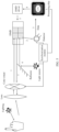
- FIG. 2 is a schematic diagram of a structure of a headlight assembly according to an embodiment of this application.
- One modulation mode may be referred to as one mask.
- the modulation mode may be preset, or may be randomly generated. There may be a plurality of modulation modes.
- the optical switch obtains, through reflection, a corresponding second light beam in each modulation mode. Therefore, one modulation mode corresponds to one second light beam.
- the optical switch When reflecting the first light beam based on the plurality of modulation modes, the optical switch obtains a plurality of second light beams.
- a higher resolution of the optical switch indicates a larger quantity of modulation modes. In other words, a larger quantity of pixels corresponding to the optical devices indicates a larger quantity of modulation modes.
- Each modulation mode corresponds to turning on of a part and turning off of a part of an area on the optical switch.
- the detector can detect light reflected by a turned-on area on the optical switch. Based on each modulation mode, the optical switch turns on a first area on the optical switch, and turns off a second area on the optical switch.
- the second light beam includes light reflected by the first area.
- the detector is configured to detect the second light beam.
- the detector After detecting the second light beam, the detector sends a detection result to a processing module.
- the processing module generates a second image based on the detection result, where the second image is a reconstructed image including the external target object.
- the detection result includes a light intensity value.
- the processing module reconstructs, by using a compression perception-based reconstruction algorithm, an image including the external target object.
- a purpose of the algorithm is to restore an external image by using light intensity data detected by the detector.
- W is a wavelet transform matrix or a compact frame transform matrix.
- This model can be solved by using an alternating direction method of multipliers ADMM.
- the processing module After obtaining the second image, the processing module detects an area corresponding to the external target object on the second image, and generates the first image based on the area corresponding to the target object.
- the target object may be detected through headlight detection or deep learning-based target detection, for example, Faster-RCNN and Yolo.
- the target object may be a person, a vehicle, a taillight of a preceding vehicle, or a headlight or a driver of an oncoming vehicle.
- the first image is a black-and-white image
- the area corresponding to the target object on the first image is black
- another area is white.
- the optical switch turns off an area of the optical switch and that corresponds to the target object, and turns on an area other than the target object on the optical switch.
- the processing module may be a part of the headlight assembly or a part of the headlight, or may be disposed on the vehicle but outside the headlight.
- the headlight assembly further includes a synchronization module.
- the synchronization module is configured to control the headlight light source, the detector, and the processing module, so that the headlight light source and the detector and the processing module work at different time. To be specific, when the detector and the processing module work, the headlight light source does not emit light, or when the headlight light source emits light, the detector and the processing module do not work.
- step numbers in FIG. 3 Light of an object outside the headlight is incident to the DMD through a lens (1).
- the DMD turns on or turns off a part of an area based on a modulation mode, and light reflected by the DMD is detected by the detector (2).
- the detector outputs a light intensity value to the processing module (3).
- the processing module reconstructs, by using a compression perception-based reconstruction algorithm, an image including the external object. After the reconstructed image is obtained, the processing module detects the target (for example, a person or a vehicle) on the reconstructed image, and sends an image in which an area corresponding to the target is black and another area is white to the DMD driver (4).
- the target for example, a person or a vehicle
- the DMD driver turns on or turns off a corresponding area of the DMD based on this image (5). Then, the light emitted by the headlight light source is incident to the DMD through the reflector (6), and no light is emitted from the turned-off area of the DMD (7), so that an anti-glare effect is implemented.
- FIG. 5 and FIG. 6 each are a schematic diagram of a structure of an imaging assembly according to an embodiment of this application.
- an optical switch is implemented by using a DMD.
- an optical switch is implemented by using an LCOS.
- a specific imaging process is similar to that in embodiments in FIG. 2 , FIG. 3 , and FIG. 4 , and details are not described herein again.
Landscapes
- Engineering & Computer Science (AREA)
- Physics & Mathematics (AREA)
- General Physics & Mathematics (AREA)
- Mechanical Engineering (AREA)
- Theoretical Computer Science (AREA)
- Multimedia (AREA)
- General Engineering & Computer Science (AREA)
- Computer Networks & Wireless Communication (AREA)
- Electromagnetism (AREA)
- Radar, Positioning & Navigation (AREA)
- Remote Sensing (AREA)
- General Health & Medical Sciences (AREA)
- Software Systems (AREA)
- Vascular Medicine (AREA)
- Health & Medical Sciences (AREA)
- Chemical & Material Sciences (AREA)
- Crystallography & Structural Chemistry (AREA)
- Lighting Device Outwards From Vehicle And Optical Signal (AREA)
- Arrangement Of Elements, Cooling, Sealing, Or The Like Of Lighting Devices (AREA)
Abstract
Description
- This application claims priority to
Chinese Patent Application No. 202111260207.9, filed with the China National Intellectual Property Administration on October 28, 2021 - This application relates to the communication field, and in particular, to a headlight assembly and a vehicle.
- As the most important lighting component of a vehicle, headlights shoulder a very important responsibility when the vehicle travels at night. Especially on roads with poor lighting, a driver needs to turn on high beam headlights to drive safely. In this case, if there is an oncoming vehicle or a preceding vehicle, the high beam headlights of the vehicle may cause glaring impact on a driver of the oncoming vehicle or the preceding vehicle, endangering driving safety. Therefore, high beam headlights with an automatic anti-glare function are produced. An anti-glare principle of the high beam headlights with the automatic anti-glare function or an adaptive driving beam (Adaptive Driving Beam, ADB) is as follows: When a sensor on the vehicle detects the oncoming vehicle or the preceding vehicle, a headlight controller automatically turns off the high beam headlights or turns off a light emitting area that is of the vehicle and that corresponds to the peer vehicle, to implement an anti-glare effect, as shown in
FIG. 1 . - To implement an ADB function, the sensor on the vehicle needs to detect an orientation of a target. Currently, a mainstream sensor is a common camera. Amain component of the common camera is a complementary metal-oxide-semiconductor (complementary metal-oxide-semiconductor, CMOS) chip. Generally, a higher resolution indicates a higher price. In addition, the camera is usually located at a location of a rear view mirror and behind a front windshield. When the ADB function is implemented, coordinate conversion needs to be performed based on a location of the camera and a location of the headlight. Therefore, relative locations of the headlight and the camera need to be calibrated before delivery.
- Embodiments of this application provide a headlight assembly, to efficiently implement an anti-glare function at low costs.
- According to a first aspect, a headlight assembly is provided, including a lens, an optical switch, and a detector. The lens is configured to converge reflected light of a target object to obtain a first light beam. The optical switch is configured to reflect the first light beam based on a modulation mode to obtain a second light beam. The detector is configured to detect the second light beam. The optical switch is further configured to: based on a first image, turn off an area of the optical switch and that corresponds to the target object, and turn on an area other than the target object on the optical switch, where the first image is generated based on the second light beam.
- The optical switch is used in a headlight to perform imaging on an external target, and an area corresponding to the target on the optical switch is turned off, so that an effect of turning off a part of an illuminated area of the headlight can be implemented, to implement a purpose of anti-glare. In addition, a common camera is no longer used for imaging, and a process in which coordinate conversion needs to be performed between a location of the camera and a location of the headlight in the conventional technology is also avoided, so that efficiency is improved and costs are reduced.
- With reference to the implementation of the first aspect, in a first possible implementation of the first aspect, that the optical switch is configured to reflect the first light beam based on a modulation mode to obtain a second light beam includes: The optical switch is configured to: based on the modulation mode, turn on a first area on the optical switch, and turn off a second area on the optical switch, where the second light beam includes light reflected by the first area.
- With reference to the first aspect or the first possible implementation of the first aspect, in a second possible implementation, the headlight assembly further includes an optical switch controller, and the optical switch controller is configured to control the optical switch to reflect the first light beam based on the modulation mode.
- With reference to any one of the first aspect or the first and second possible implementations of the first aspect, in a third possible implementation, the optical switch includes a plurality of optical devices, and that the optical switch is configured to reflect the first light beam based on a modulation mode includes: The plurality of optical devices are configured to reflect the first light beam based on the modulation mode.
- With reference to any one of the first aspect or the first to third possible implementations of the first aspect, in a fourth possible implementation, the optical switch controller is configured to: control an optical device in the first area to be turned on, and control an optical device in the second area to be turned off.
- With reference to any one of the first aspect or the first to fourth possible implementations of the first aspect, in a fifth possible implementation, the optical switch controller is configured to: control an optical device in the area corresponding to the target object to be turned off, and control an optical device in the area other than the target object to be turned on.
- The optical device in the area corresponding to the target object is turned off, to implement an anti-glare effect on the target object. The optical device in the area other than the target object is turned on, to implement a lighting effect.
- With reference to any one of the first aspect or the first to fifth possible implementations of the first aspect, in a sixth possible implementation, there are a plurality of modulation modes, and each modulation mode corresponds to one second light beam.
- With reference to any one of the first aspect or the first to sixth possible implementations of the first aspect, in a seventh possible implementation, a larger quantity of pixels corresponding to the optical devices indicates a larger quantity of modulation modes.
- With reference to any one of the first aspect or the first to seventh possible implementations of the first aspect, in an eighth possible implementation, the headlight assembly further includes a processing module; the processing module is configured to generate a second image based on a detection result obtained by the detector by detecting the second light beam, where the second image includes the target object; and the processing module is further configured to detect a corresponding area of the target object on the second image, and generate the first image based on the corresponding area.
- A part of an area on the optical switch is turned on or turned off based on the plurality of modulation modes, and the second image is generated by the processing module based on the detection result of the detector, to implement an effect of reconstructing an external environment image.
- With reference to any one of the first aspect or the first to eighth possible implementations of the first aspect, in a ninth possible implementation, the optical switch is a digital micromirror device (Digital Micromirror Device, DMD).
- With reference to any one of the first aspect or the first to ninth possible implementations of the first aspect, in a tenth possible implementation, the optical switch is a liquid crystal on silicon (Liquid Crystal on Silicon, LCOS).
- With reference to any one of the first aspect or the first to tenth possible implementations of the first aspect, in an eleventh possible implementation, the headlight assembly further includes a polarization conversion system PCS, and the PCS is configured to polarize converged reflected light of the target image to obtain the first light beam.
- With reference to any one of the first aspect or the first to eleventh possible implementations of the first aspect, in a twelfth possible implementation, the headlight assembly further includes a headlight light source, and the optical switch is further configured to reflect light emitted by the headlight light source.
- With reference to any one of the first aspect or the first to twelfth possible implementations of the first aspect, in a thirteenth possible implementation, the headlight assembly further includes a synchronization module; the synchronization module is configured to control the headlight light source, the detector, and the processing module; and when the detector and the processing module work, the headlight light source does not emit light; or when the headlight light source emits light, the detector and the processing module do not work.
- According to a second aspect, a vehicle is provided, including the headlight assembly according to any one of the first aspect or the implementations of the first aspect.
- According to a third aspect, a headlight anti-glare method is provided, and is applied to the headlight assembly according to any one of the first aspect or the implementations of the first aspect. When an area corresponding to a target object is turned off, light that is emitted by a headlight light source and reflected by the area of the target object does not illuminate the target object. An anti-glare effect is implemented.
- According to a fourth aspect, an imaging assembly is provided, including a lens, an optical switch, a detector, a color wheel, and a light source. The light source, the color wheel, and the optical switch are configured to present a first picture. The lens is configured to converge reflected light of a target object to obtain a first light beam. The optical switch is configured to reflect the first light beam based on a modulation mode to obtain a second light beam. The detector is configured to detect the second light beam. The light source, the color wheel, and the optical switch are further configured to present a second picture based on a first image, where the first image is generated based on the second light beam.
- The optical switch is used in a projection device to perform imaging on an external target, and a next operation of a user is determined based on an imaging result, to implement an effect of presenting a picture obtained after the operation to the user. In addition, a common camera is no longer used for imaging, and costs are reduced.
- With reference to the implementation of the fourth aspect, in a first possible implementation of the fourth aspect, that the optical switch is configured to reflect the first light beam based on a modulation mode includes: The optical switch is configured to: based on the modulation mode, turn on a first area on the optical switch, and turn off a second area on the optical switch, where the second light beam includes light reflected by the first area.
- With reference to the fourth aspect or the first possible implementation of the fourth aspect, in a second possible implementation, the imaging assembly further includes a processing module; and the processing module is configured to generate the first image based on a detection result obtained by the detector by detecting the second light beam, where the first image indicates the optical switch to turn on or turn off a part of an area on the optical switch.
- With reference to any one of the fourth aspect or the first and second possible implementations of the fourth aspect, in a third possible implementation, before generating the first image, the processing module is further configured to generate a second image based on the detection result, where the second image includes the target object; and the processing module is further configured to: detect a corresponding area of the target object on the second image, and generate the first image based on the corresponding area.
- With reference to any one of the fourth aspect or the first to third possible implementations of the fourth aspect, in a fourth possible implementation, the optical switch is a digital micromirror device DMD.
- With reference to any one of the fourth aspect or the first to fourth possible implementations of the fourth aspect, in a fifth possible implementation, the optical switch is a liquid crystal on silicon LCOS.
- With reference to any one of the fourth aspect or the first to fifth possible implementations of the fourth aspect, in a sixth possible implementation, the imaging assembly further includes a polarization conversion system PCS, and the PCS is configured to polarize converged reflected light of the target image to obtain the first light beam.
- According to a fifth aspect, a projection device is provided, including the imaging assembly according to any one of the fourth aspect or the implementations of the fourth aspect.
- To describe the technical solutions in embodiments of this application or the conventional technology more clearly, the following briefly describes the accompanying drawings in descriptions of embodiments and the conventional technology.
-
FIG. 1 is a schematic diagram of anti-glare of a headlight; -
FIG. 2 is a schematic diagram of a structure of a headlight assembly according to an embodiment of this application; -
FIG. 3 is a schematic diagram of a structure of a headlight assembly implemented by using a DMD according to an embodiment of this application; -
FIG. 4 is a schematic diagram of a structure of a headlight assembly implemented by using an LCOS according to an embodiment of this application; -
FIG. 5 is a schematic diagram of a structure of an imaging assembly implemented by using a DMD according to an embodiment of this application; and -
FIG. 6 is a schematic diagram of a structure of an imaging assembly implemented by using an LCOS according to an embodiment of this application. - A digital micromirror device DMD is a pixel matrix including a plurality of micromirrors, and can adjust a direction of incident light by rotating a reflector. A size of the matrix corresponds to a resolution of the DMD, for example, 800x600, 1024x768, 1280x720, and 1920x1080. Each micromirror in the DMD can be separately turned on or off.
- A liquid crystal on silicon LCOS is a very small-sized matrix liquid crystal display apparatus based on a reflection mode. Each pixel is turned on and off by using a separate circuit. The LCOS controls a projected display image by modulating intensity or a phase of incident light. A size of a pixel matrix corresponds to a resolution of the LCOS. The incident light is converted into polarized light by a polarization conversion system (Polarization Conversion System, PCS). If a liquid crystal is modulated by an external signal and is at a bright display level, after the polarized light is modulated by the LCOS, a polarization direction is rotated by 90 degrees, and the light is displayed in a bright state. When the liquid crystal is at a dark display level, after the polarized light is modulated, the polarization direction does not change, and the light is displayed in a dark state.
-
FIG. 2 is a schematic diagram of a structure of a headlight assembly according to an embodiment of this application. - The headlight assembly includes a lens, an optical switch, and a detector. The lens is configured to converge reflected light of a target object outside a headlight, to obtain a first light beam. The target object may be a vehicle, a pedestrian, a road sign, a traffic light, or the like. There may be one or more lenses. The first light beam is incident on the optical switch. The optical switch may be a DMD or an LCOS. The optical switch has a plurality of optical devices. When the optical switch is implemented by using the DMD, the plurality of optical devices include a pixel matrix including a plurality of micromirrors. When the optical switch is implemented by using the LCOS, the plurality of optical devices include a pixel matrix including a liquid crystal on silicon. The optical switch is configured to reflect the first light beam based on a modulation mode to obtain a second light beam.
- The headlight assembly may further include an optical switch controller. The optical switch optical controller is configured to control the optical switch to reflect the first light beam based on the modulation mode. Specifically, when the optical switch is implemented by using the DMD, the optical switch controller is a DMD driver. When the optical switch is implemented by using the LCOS, the optical switch controller is an LCOS driver. The optical switch controller is specifically configured to control the plurality of optical devices on the optical switch to reflect the first light beam based on the modulation mode.
- One modulation mode may be referred to as one mask. The modulation mode may be preset, or may be randomly generated. There may be a plurality of modulation modes. The optical switch obtains, through reflection, a corresponding second light beam in each modulation mode. Therefore, one modulation mode corresponds to one second light beam. When reflecting the first light beam based on the plurality of modulation modes, the optical switch obtains a plurality of second light beams. A higher resolution of the optical switch indicates a larger quantity of modulation modes. In other words, a larger quantity of pixels corresponding to the optical devices indicates a larger quantity of modulation modes.
- Each modulation mode corresponds to turning on of a part and turning off of a part of an area on the optical switch. The detector can detect light reflected by a turned-on area on the optical switch. Based on each modulation mode, the optical switch turns on a first area on the optical switch, and turns off a second area on the optical switch. The second light beam includes light reflected by the first area. The detector is configured to detect the second light beam.
- Specifically, the optical switch controller controls an optical device in the first area to be turned on, and controls an optical device in the second area to be turned off. When the optical switch is implemented by using the DMD, the DMD driver controls a micromirror in a first area on the DMD to be turned on and a micromirror in a second area to be turned off. Light reflected by the micromirror in the first area can be detected by the detector, and light reflected by the micromirror in the second area cannot be detected by the detector. When the optical switch is implemented by using the LCOS, the LCOS driver controls a liquid crystal in a first area on the LCOS to be turned on and a liquid crystal in a second area to be turned off. The turned-on liquid crystal is in a bright display level state, and the turned-off liquid crystal is in a dark display level state. Light reflected by the liquid crystal in the first area can be detected by the detector, and light displayed by the liquid crystal in the second area cannot be detected by the detector. The detector may be a light detector.
- For the light reflected by the turned-off area on the optical switch, an absorber may be added to shield the light, to prevent the detector from detecting the light. Alternatively, a reflection direction of the turned-off area may be adjusted, to prevent the detector from detecting the light.
- After detecting the second light beam, the detector sends a detection result to a processing module. The processing module generates a second image based on the detection result, where the second image is a reconstructed image including the external target object. In an implementation, the detection result includes a light intensity value. When the light intensity value sent by the detector to the processing module accumulates to a specific quantity, the processing module reconstructs, by using a compression perception-based reconstruction algorithm, an image including the external target object. A purpose of the algorithm is to restore an external image by using light intensity data detected by the detector.
- For example, the optical switch is implemented by using the DMD. The reconstruction algorithm is as follows:
- It is assumed that an original image of a photographed external image is I, and I is an image that needs to be reconstructed by using the reconstruction algorithm. It is assumed that a mask of the DMD is P, and a signal detected by the detector is S. In this case, S = P × 1. Herein, S and I are vectors, and P is a matrix. An intermediate result is enabled to be u = WI, and the following minimization problem is solved to obtain u:

- Therefore,

- Herein, W is a wavelet transform matrix or a compact frame transform matrix. Then, the reconstructed image I may be obtained by using the formula I = W Tu. This model can be solved by using an alternating direction method of multipliers ADMM.
- After obtaining the second image, the processing module detects an area corresponding to the external target object on the second image, and generates the first image based on the area corresponding to the target object. The target object may be detected through headlight detection or deep learning-based target detection, for example, Faster-RCNN and Yolo. The target object may be a person, a vehicle, a taillight of a preceding vehicle, or a headlight or a driver of an oncoming vehicle. In an implementation, the first image is a black-and-white image, the area corresponding to the target object on the first image is black, and another area is white. Based on the first image, the optical switch turns off an area of the optical switch and that corresponds to the target object, and turns on an area other than the target object on the optical switch.
- Specifically, the optical switch controller controls an optical device in the area ofthe optical switch and that corresponds to the target object to be turned on, and controls an optical device in the area other than the target object on the optical switch to be turned off. When the optical switch is implemented by using the DMD, the processing module sends the first image to the DMD driver, and the DMD driver controls, based on the first image, a micromirror in an area of the DMD and that corresponds to the target object to be turned off, and a micromirror in another area to be turned on. When the optical switch is implemented by using the LCOS, the processing module sends the first image to the LCOS driver, and the LCOS driver controls, based on the first image, a liquid crystal in an area of the LCOS and that corresponds to the target object to be turned off, and a liquid crystal in another area to be turned on.
- Then, light emitted by a headlight light source is incident to the optical switch. Through reflection of the optical switch, light reflected by the area other than the target object is emitted from the headlight and illuminates an external environment, and light reflected by the area corresponding to the target object is not emitted from the headlight and does not illuminate the target object. In this way, an anti-glare effect is implemented.
- The processing module may be a part of the headlight assembly or a part of the headlight, or may be disposed on the vehicle but outside the headlight.
- The headlight assembly further includes a synchronization module. The synchronization module is configured to control the headlight light source, the detector, and the processing module, so that the headlight light source and the detector and the processing module work at different time. To be specific, when the detector and the processing module work, the headlight light source does not emit light, or when the headlight light source emits light, the detector and the processing module do not work.
- The headlight light source may be a part of the headlight assembly, or may be outside the headlight assembly.
-
FIG. 3 is a schematic diagram of a structure of a headlight assembly implemented by using a DMD according to an embodiment of this application. InFIG. 3 , an optical switch is implemented by using the DMD. An optical switch controller is a DMD driver, and a processing module is implemented by using a CPU. A headlight light source, the processing module, and a detector are controlled by using a synchronization module, so that when the DMD, the detector, the processing module, and the DMD driver perform imaging on an external object, the headlight light source is turned off. In this way, the headlight light source does not affect imaging of the external object. The headlight assembly may further include a reflector, configured to reflect light emitted by the headlight light source to the DMD. - Refer to step numbers in
FIG. 3 . Light of an object outside the headlight is incident to the DMD through a lens (1). The DMD turns on or turns off a part of an area based on a modulation mode, and light reflected by the DMD is detected by the detector (2). The detector outputs a light intensity value to the processing module (3). When the light intensity value output by the detector to the processing module accumulates to a specific quantity, the processing module reconstructs, by using a compression perception-based reconstruction algorithm, an image including the external object. After the reconstructed image is obtained, the processing module detects the target (for example, a person or a vehicle) on the reconstructed image, and sends an image in which an area corresponding to the target is black and another area is white to the DMD driver (4). The DMD driver turns on or turns off a corresponding area of the DMD based on this image (5). Then, the light emitted by the headlight light source is incident to the DMD through the reflector (6), and no light is emitted from the turned-off area of the DMD (7), so that an anti-glare effect is implemented. -
FIG. 4 is a schematic diagram of a structure of a headlight assembly implemented by using an LCOS according to an embodiment of this application. InFIG. 4 , an optical switch is implemented by using the LCOS. An optical switch controller is an LCOS driver, and a processing module is implemented by using a CPU. A headlight light source, the processing module, and a detector are controlled by using a synchronization module, so that when the LCOS, the detector, the processing module, and the LCOS driver perform imaging on an external object, the headlight light source is turned off. In this way, the headlight light source does not affect imaging of the external object. Due to different liquid crystal imaging principles, the headlight assembly may include a PCS, configured to convert incident light into polarized light. The PCS may convert the incident light into S-polarized light or P-polarized light. The headlight assembly may further include a polarization beam splitter (Polarization Beam Splitter, PBS), configured to reflect or transmit the polarized light. The PBS can reflect different polarized light based on different types of reflective films pasted on the PBS. For example, if a reflective film that reflects only the S-polarized light is pasted on the PBS, the PBS reflects only the S-polarized light, and does not reflect the P-polarized light. The P-polarized light is transmitted through the PBS. The following uses an example in which polarized light converted by aPCS 1 is P-polarized light, polarized light converted by aPCS 2 is S-polarized light, and a reflective film that reflects only the S-polarized light is pasted on the PBS for description (if the polarized light converted by thePCS 1 is S-polarized light, and the polarized light converted by thePCS 2 is P-polarized light, a reflective film that reflects only the P-polarized light needs to be pasted on the PBS). - Refer to step numbers in
FIG. 4 . Light of an object outside the headlight passes through the lens, and is converted into P-polarized light through thePCS 1. The P-polarized light is incident to the LCOS (1). The LCOS turns on or turns off a part of an area based on a modulation mode. The P-polarized light becomes S-polarized light after being reflected by the LCOS, and is detected by the detector (2). The detector outputs a light intensity value to the processing module (3). When the light intensity value output by the detector to the processing module accumulates to a specific quantity, the processing module reconstructs, by using a compression perception-based reconstruction algorithm, an image including the external object. After the reconstructed image is obtained, the processing module detects the target (for example, a person or a vehicle) on the reconstructed image, and sends an image in which an area corresponding to the target is black and another area is white to the LCOS driver (4). The LCOS driver turns on or turns off a corresponding area of the LCOS based on this image (5). Then, light emitted by a headlight light source is converted into S-polarized light through the PCS 2 (6 and 7). After being reflected by the PBS, the S-polarized light is incident to the LCOS (8). No light is emitted from the turned-off area of the LCOS. Light reflected by the turned-on area of the LCOS changes from the S-polarized light to P-polarized light. The P-polarized light transmits through the PBS and is emitted through the lens (9). In this way, an anti-glare effect is implemented. - For a process of reconstructing an image and performing target detection by the processing module in embodiments in
FIG. 3 andFIG. 4 , refer to related descriptions in embodiments inFIG. 2 . Details are not described again. - It can be learned from the foregoing that the optical switch is used in a headlight to perform imaging on an external target, and an area corresponding to the target on the optical switch is turned off, so that an effect of turning off a part of an illuminated area of the headlight can be implemented, to implement a purpose of anti-glare. In addition and a process in which coordinate conversion needs to be performed between a location of the camera and a location of the headlight in the conventional technology is also avoided.
-
FIG. 5 andFIG. 6 each are a schematic diagram of a structure of an imaging assembly according to an embodiment of this application. InFIG. 5 , an optical switch is implemented by using a DMD. InFIG. 6 , an optical switch is implemented by using an LCOS. A specific imaging process is similar to that in embodiments inFIG. 2 ,FIG. 3 , andFIG. 4 , and details are not described herein again. - The imaging assembly may be applied to a projection device. The imaging assembly may be configured to: detect a location and an action of a hand of a user, determine a current operation of the user based on the location and the action of the hand of the user, update a projected picture based on the operation of the user, and wait for a next operation of the user. For example, if the projection device currently projects an application picture, the application picture includes an icon button, and the imaging assembly detects an action of tapping the icon button by the user, a next picture presented by the imaging assembly is a picture obtained after the application is entered. Alternatively, for example, if the projection device currently projects a photo, and the imaging assembly detects an action of double tapping the photo by the user, a next picture presented by the imaging assembly is an enlarged photo.
- The foregoing descriptions are merely specific implementations of this application, but are not intended to limit the protection scope of this application. Any variation or replacement readily figured out by a person skilled in the art within the technical scope disclosed in this application shall fall within the protection scope of this application. Therefore, the protection scope of this application shall be subject to the protection scope of the claims.
Claims (22)
- A headlight assembly, comprising a lens, an optical switch, and a detector, whereinthe lens is configured to converge reflected light of a target object to obtain a first light beam;the optical switch is configured to reflect the first light beam based on a modulation mode to obtain a second light beam;the detector is configured to detect the second light beam; andthe optical switch is further configured to: based on a first image, turn off an area of the optical switch and that corresponds to the target object, and turn on an area other than the target object on the optical switch, wherein the first image is generated based on the second light beam.
- The headlight assembly according to claim 1, wherein that the optical switch is configured to reflect the first light beam based on a modulation mode to obtain a second light beam comprises: the optical switch is configured to: based on the modulation mode, turn on a first area on the optical switch, and turn off a second area on the optical switch, wherein the second light beam comprises light reflected by the first area.
- The headlight assembly according to claim 1 or 2, wherein the headlight assembly further comprises an optical switch controller, and the optical switch controller is configured to control the optical switch to reflect the first light beam based on the modulation mode.
- The headlight assembly according to claim 3, wherein the optical switch comprises a plurality of optical devices, and that the optical switch is configured to reflect the first light beam based on a modulation mode comprises:the plurality of optical devices are configured to reflect the first light beam based on the modulation mode; andthe optical switch controller is configured to: control an optical device in the first area to be turned on, and control an optical device in the second area to be turned off.
- The headlight assembly according to claim 4, wherein the optical switch controller is configured to: control an optical device in the area corresponding to the target object to be turned off, and control an optical device in the area other than the target object to be turned on.
- The headlight assembly according to claims 1 to 5, wherein there are a plurality of modulation modes, and each modulation mode corresponds to one second light beam.
- The headlight assembly according to claim 6, wherein a larger quantity of pixels corresponding to the optical devices indicates a larger quantity of modulation modes.
- The headlight assembly according to any one of claims 1 to 7, wherein the headlight assembly further comprises a processing module; the processing module is configured to generate a second image based on a detection result obtained by the detector by detecting the second light beam, wherein the second image comprises the target object; and the processing module is further configured to detect a corresponding area of the target object on the second image, and generate the first image based on the corresponding area.
- The headlight assembly according to any one of claims 1 to 8, wherein the optical switch is a digital micromirror device DMD.
- The headlight assembly according to any one of claims 1 to 8, wherein the optical switch is a liquid crystal on silicon LCOS.
- The headlight assembly according to claim 10, wherein the headlight assembly further comprises a polarization conversion system PCS, and the PCS is configured to polarize converged reflected light of the target image to obtain the first light beam.
- The headlight assembly according to any one of claims 1 to 11, wherein the headlight assembly further comprises a headlight light source, and the optical switch is further configured to reflect light emitted by the headlight light source.
- The headlight assembly according to claim 12, wherein the headlight assembly further comprises a synchronization module; the synchronization module is configured to control the headlight light source, the detector, and the processing module; and when the detector and the processing module work, the headlight light source does not emit light; or when the headlight light source emits light, the detector and the processing module do not work.
- A vehicle, comprising the headlight assembly according to any one of claims 1 to 13.
- An imaging assembly, comprising a lens, an optical switch, a detector, a color wheel, and a light source, whereinthe optical switch is configured to reflect light emitted by the light source, and the color wheel is configured to add a color to the light reflected by the optical switch, to present a first picture;the lens is configured to converge reflected light of a target object to obtain a first light beam;the optical switch is configured to reflect the first light beam based on a modulation mode to obtain a second light beam;the detector is configured to detect the second light beam; andthe optical switch is further configured to reflect, based on a first image, the light emitted by the light source, and the color wheel is further configured to add a color to the light reflected by the optical switch based on the first image, to present a second picture, wherein content of the second picture is different from content of the first picture, and the first image is generated based on the second light beam.
- The imaging assembly according to claim 15, wherein that the optical switch is configured to reflect the first light beam based on a modulation mode comprises: the optical switch is configured to: based on the modulation mode, turn on a first area on the optical switch, and turn off a second area on the optical switch, wherein the second light beam comprises light reflected by the first area.
- The imaging assembly according to claim 15 or 16, wherein the imaging assembly further comprises a processing module; and the processing module is configured to generate the first image based on a detection result obtained by the detector by detecting the second light beam, wherein the first image indicates the optical switch to turn on or turn off a part of an area on the optical switch.
- The imaging assembly according to claim 17, wherein before generating the first image, the processing module is further configured to generate a second image based on the detection result, wherein the second image comprises the target object; and the processing module is further configured to: detect a corresponding area of the target object on the second image, and generate the first image based on the corresponding area.
- The imaging assembly according to any one of claims 15 to 18, wherein the optical switch is a digital micromirror device DMD.
- The imaging assembly according to any one of claims 15 to 18, wherein the optical switch is a liquid crystal on silicon LCOS.
- The imaging assembly according to claim 20, wherein the imaging assembly further comprises a polarization conversion system PCS, and the PCS is configured to polarize converged reflected light of the target image to obtain the first light beam.
- A projection device, comprising the imaging assembly according to any one of claims 15 to 21.
Applications Claiming Priority (2)
| Application Number | Priority Date | Filing Date | Title |
|---|---|---|---|
| CN202111260207.9A CN116039490A (en) | 2021-10-28 | 2021-10-28 | Vehicle light assembly and vehicle |
| PCT/CN2022/102101 WO2023071262A1 (en) | 2021-10-28 | 2022-06-29 | Vehicle lamp assembly and transportation vehicle |
Publications (2)
| Publication Number | Publication Date |
|---|---|
| EP4397542A1 true EP4397542A1 (en) | 2024-07-10 |
| EP4397542A4 EP4397542A4 (en) | 2025-05-28 |
Family
ID=86129958
Family Applications (1)
| Application Number | Title | Priority Date | Filing Date |
|---|---|---|---|
| EP22885167.1A Pending EP4397542A4 (en) | 2021-10-28 | 2022-06-29 | VEHICLE LAMP ARRANGEMENT AND TRANSPORT VEHICLE |
Country Status (4)
| Country | Link |
|---|---|
| EP (1) | EP4397542A4 (en) |
| JP (1) | JP7753537B2 (en) |
| CN (1) | CN116039490A (en) |
| WO (1) | WO2023071262A1 (en) |
Families Citing this family (1)
| Publication number | Priority date | Publication date | Assignee | Title |
|---|---|---|---|---|
| CN118596982B (en) * | 2023-12-25 | 2025-05-20 | 深圳引望智能技术有限公司 | Car light system, car light and vehicle |
Family Cites Families (16)
| Publication number | Priority date | Publication date | Assignee | Title |
|---|---|---|---|---|
| US20080198372A1 (en) * | 2007-02-21 | 2008-08-21 | Spatial Photonics, Inc. | Vehicle headlight with image display |
| CN101830193B (en) * | 2010-04-19 | 2012-12-19 | 范桦 | Intelligent car light device capable imaging on road surface |
| KR101811595B1 (en) * | 2015-09-04 | 2017-12-22 | 엘지전자 주식회사 | Headlamp for vehicle and Vehicle including the same |
| CN107128240A (en) * | 2016-02-29 | 2017-09-05 | 长城汽车股份有限公司 | The illuminator and its control method of vehicle, vehicle |
| CN106016130A (en) * | 2016-07-19 | 2016-10-12 | 开发晶照明(厦门)有限公司 | Headlight device and vehicle |
| EP3489577B1 (en) * | 2017-11-27 | 2021-11-24 | ZKW Group GmbH | Lighting device for a motor vehicle headlight |
| DE102018209941A1 (en) * | 2018-06-20 | 2019-12-24 | Osram Gmbh | Optical arrangement, spotlights and procedures |
| WO2020243038A1 (en) * | 2019-05-28 | 2020-12-03 | Optonomous Technologies, Inc. | Lidar integrated with smart headlight and method |
| CN112113184A (en) * | 2019-06-21 | 2020-12-22 | 深圳市中光工业技术研究院 | Lighting system with detection function |
| US11524625B2 (en) * | 2019-12-12 | 2022-12-13 | Texas Instruments Incorporated | Adaptive vehicle headlight |
| CN113126405B (en) * | 2019-12-31 | 2022-12-27 | 华为技术有限公司 | Projection device and projection interaction method |
| JP7542051B2 (en) * | 2020-02-12 | 2024-08-29 | 株式会社小糸製作所 | Vehicle headlights |
| CN111239765A (en) * | 2020-03-19 | 2020-06-05 | 深圳元戎启行科技有限公司 | Active lighting correlation imaging system and active lighting correlation imaging method |
| CZ310588B6 (en) * | 2020-03-24 | 2026-01-07 | PO LIGHTING CZECH s.r.o. | An adaptive signalling and/or illuminating light system of a motor vehicle |
| CN111469756B (en) * | 2020-04-10 | 2021-12-31 | 合肥全色光显科技有限公司 | Intelligent lighting system of motor vehicle |
| CN112954284A (en) * | 2021-02-08 | 2021-06-11 | 青岛海信激光显示股份有限公司 | Display method of projection picture and laser projection equipment |
-
2021
- 2021-10-28 CN CN202111260207.9A patent/CN116039490A/en active Pending
-
2022
- 2022-06-29 EP EP22885167.1A patent/EP4397542A4/en active Pending
- 2022-06-29 JP JP2024525271A patent/JP7753537B2/en active Active
- 2022-06-29 WO PCT/CN2022/102101 patent/WO2023071262A1/en not_active Ceased
Also Published As
| Publication number | Publication date |
|---|---|
| EP4397542A4 (en) | 2025-05-28 |
| WO2023071262A1 (en) | 2023-05-04 |
| JP7753537B2 (en) | 2025-10-14 |
| CN116039490A (en) | 2023-05-02 |
| JP2024536615A (en) | 2024-10-04 |
Similar Documents
| Publication | Publication Date | Title |
|---|---|---|
| JP4345745B2 (en) | Multi-projection display | |
| US9335613B2 (en) | Projector having an adjuster to adjust an angle of a projector lens | |
| JP6535834B2 (en) | Method and system for controlling a laser based lighting system | |
| CN108459455A (en) | A kind of projection display system | |
| TW201520599A (en) | Head-up display system | |
| US20110241990A1 (en) | Projection apparatus and location method for determining a position of a light point on a projection image | |
| US12003898B2 (en) | Projector and projection method | |
| JP2019057797A (en) | Night vision imaging device | |
| CN103744258B (en) | A kind of head-up display method and system | |
| US7959306B2 (en) | Displaying method of digital light processing (DLP) projector and DLP projector using the same | |
| JP7753537B2 (en) | Headlight assembly and vehicle | |
| US20200099901A1 (en) | Projection device and light source module thereof and method of synchronizing wavelength conversion wheel and filter wheel | |
| JP2000028988A (en) | LCD projector | |
| JP2002234360A (en) | Vehicle display device and display method thereof | |
| WO2015025479A1 (en) | Heads-up display device | |
| CN101477246B (en) | Display method of digital light processing projection device and digital light processing projection device | |
| CN108152960A (en) | Vehicle-mounted head-up display method and system | |
| JP2015118220A (en) | Image display device and control device | |
| KR20180121262A (en) | Adaptive driving beam head lamp for vehicle using liquid crystal on silicon panel | |
| EP4098470A1 (en) | Operating method of optical system in vehicle | |
| JP2002268015A (en) | Projection type image display device | |
| JP2007065542A (en) | Image projection device | |
| TWI579675B (en) | Laser dimming system | |
| JP2021017064A (en) | Head-up display device | |
| CN111965664A (en) | Light emitting device, imaging system, and emission light modulation method |
Legal Events
| Date | Code | Title | Description |
|---|---|---|---|
| STAA | Information on the status of an ep patent application or granted ep patent |
Free format text: STATUS: THE INTERNATIONAL PUBLICATION HAS BEEN MADE |
|
| PUAI | Public reference made under article 153(3) epc to a published international application that has entered the european phase |
Free format text: ORIGINAL CODE: 0009012 |
|
| STAA | Information on the status of an ep patent application or granted ep patent |
Free format text: STATUS: REQUEST FOR EXAMINATION WAS MADE |
|
| 17P | Request for examination filed |
Effective date: 20240404 |
|
| AK | Designated contracting states |
Kind code of ref document: A1 Designated state(s): AL AT BE BG CH CY CZ DE DK EE ES FI FR GB GR HR HU IE IS IT LI LT LU LV MC MK MT NL NO PL PT RO RS SE SI SK SM TR |
|
| RAP1 | Party data changed (applicant data changed or rights of an application transferred) |
Owner name: SHENZHEN YINWANG INTELLIGENTTECHNOLOGIES CO., LTD. |
|
| REG | Reference to a national code |
Ref country code: DE Ref legal event code: R079 Free format text: PREVIOUS MAIN CLASS: B60Q0001040000 Ipc: B60Q0001000000 |
|
| DAV | Request for validation of the european patent (deleted) | ||
| DAX | Request for extension of the european patent (deleted) | ||
| RIC1 | Information provided on ipc code assigned before grant |
Ipc: G01S 17/00 20200101ALI20250129BHEP Ipc: G06V 10/00 20220101ALI20250129BHEP Ipc: F21S 41/675 20180101ALI20250129BHEP Ipc: F21S 41/64 20180101ALI20250129BHEP Ipc: B60Q 1/14 20060101ALI20250129BHEP Ipc: B60Q 1/00 20060101AFI20250129BHEP |
|
| A4 | Supplementary search report drawn up and despatched |
Effective date: 20250429 |
|
| RIC1 | Information provided on ipc code assigned before grant |
Ipc: G01S 17/00 20200101ALI20250423BHEP Ipc: G06V 10/00 20220101ALI20250423BHEP Ipc: F21S 41/675 20180101ALI20250423BHEP Ipc: F21S 41/64 20180101ALI20250423BHEP Ipc: B60Q 1/14 20060101ALI20250423BHEP Ipc: B60Q 1/00 20060101AFI20250423BHEP |