EP4397520A1 - Work vehicle - Google Patents
Work vehicle Download PDFInfo
- Publication number
- EP4397520A1 EP4397520A1 EP23215999.6A EP23215999A EP4397520A1 EP 4397520 A1 EP4397520 A1 EP 4397520A1 EP 23215999 A EP23215999 A EP 23215999A EP 4397520 A1 EP4397520 A1 EP 4397520A1
- Authority
- EP
- European Patent Office
- Prior art keywords
- power
- travel
- work
- power transmission
- state
- Prior art date
- Legal status (The legal status is an assumption and is not a legal conclusion. Google has not performed a legal analysis and makes no representation as to the accuracy of the status listed.)
- Pending
Links
Images




Classifications
-
- B—PERFORMING OPERATIONS; TRANSPORTING
- B60—VEHICLES IN GENERAL
- B60L—PROPULSION OF ELECTRICALLY-PROPELLED VEHICLES; SUPPLYING ELECTRIC POWER FOR AUXILIARY EQUIPMENT OF ELECTRICALLY-PROPELLED VEHICLES; ELECTRODYNAMIC BRAKE SYSTEMS FOR VEHICLES IN GENERAL; MAGNETIC SUSPENSION OR LEVITATION FOR VEHICLES; MONITORING OPERATING VARIABLES OF ELECTRICALLY-PROPELLED VEHICLES; ELECTRIC SAFETY DEVICES FOR ELECTRICALLY-PROPELLED VEHICLES
- B60L1/00—Supplying electric power to auxiliary equipment of vehicles
-
- B—PERFORMING OPERATIONS; TRANSPORTING
- B60—VEHICLES IN GENERAL
- B60K—ARRANGEMENT OR MOUNTING OF PROPULSION UNITS OR OF TRANSMISSIONS IN VEHICLES; ARRANGEMENT OR MOUNTING OF PLURAL DIVERSE PRIME-MOVERS IN VEHICLES; AUXILIARY DRIVES FOR VEHICLES; INSTRUMENTATION OR DASHBOARDS FOR VEHICLES; ARRANGEMENTS IN CONNECTION WITH COOLING, AIR INTAKE, GAS EXHAUST OR FUEL SUPPLY OF PROPULSION UNITS IN VEHICLES
- B60K1/00—Arrangement or mounting of electrical propulsion units
- B60K1/02—Arrangement or mounting of electrical propulsion units comprising more than one electric motor
-
- B—PERFORMING OPERATIONS; TRANSPORTING
- B60—VEHICLES IN GENERAL
- B60K—ARRANGEMENT OR MOUNTING OF PROPULSION UNITS OR OF TRANSMISSIONS IN VEHICLES; ARRANGEMENT OR MOUNTING OF PLURAL DIVERSE PRIME-MOVERS IN VEHICLES; AUXILIARY DRIVES FOR VEHICLES; INSTRUMENTATION OR DASHBOARDS FOR VEHICLES; ARRANGEMENTS IN CONNECTION WITH COOLING, AIR INTAKE, GAS EXHAUST OR FUEL SUPPLY OF PROPULSION UNITS IN VEHICLES
- B60K17/00—Arrangement or mounting of transmissions in vehicles
- B60K17/02—Arrangement or mounting of transmissions in vehicles characterised by arrangement, location, or kind of clutch
-
- B—PERFORMING OPERATIONS; TRANSPORTING
- B60—VEHICLES IN GENERAL
- B60K—ARRANGEMENT OR MOUNTING OF PROPULSION UNITS OR OF TRANSMISSIONS IN VEHICLES; ARRANGEMENT OR MOUNTING OF PLURAL DIVERSE PRIME-MOVERS IN VEHICLES; AUXILIARY DRIVES FOR VEHICLES; INSTRUMENTATION OR DASHBOARDS FOR VEHICLES; ARRANGEMENTS IN CONNECTION WITH COOLING, AIR INTAKE, GAS EXHAUST OR FUEL SUPPLY OF PROPULSION UNITS IN VEHICLES
- B60K17/00—Arrangement or mounting of transmissions in vehicles
- B60K17/28—Arrangement or mounting of transmissions in vehicles characterised by arrangement, location, or type of power take-off
-
- B—PERFORMING OPERATIONS; TRANSPORTING
- B60—VEHICLES IN GENERAL
- B60K—ARRANGEMENT OR MOUNTING OF PROPULSION UNITS OR OF TRANSMISSIONS IN VEHICLES; ARRANGEMENT OR MOUNTING OF PLURAL DIVERSE PRIME-MOVERS IN VEHICLES; AUXILIARY DRIVES FOR VEHICLES; INSTRUMENTATION OR DASHBOARDS FOR VEHICLES; ARRANGEMENTS IN CONNECTION WITH COOLING, AIR INTAKE, GAS EXHAUST OR FUEL SUPPLY OF PROPULSION UNITS IN VEHICLES
- B60K25/00—Auxiliary drives
-
- B—PERFORMING OPERATIONS; TRANSPORTING
- B62—LAND VEHICLES FOR TRAVELLING OTHERWISE THAN ON RAILS
- B62D—MOTOR VEHICLES; TRAILERS
- B62D49/00—Tractors
- B62D49/06—Tractors adapted for multi-purpose use
-
- A—HUMAN NECESSITIES
- A01—AGRICULTURE; FORESTRY; ANIMAL HUSBANDRY; HUNTING; TRAPPING; FISHING
- A01D—HARVESTING; MOWING
- A01D34/00—Mowers; Mowing apparatus of harvesters
- A01D34/01—Mowers; Mowing apparatus of harvesters characterised by features relating to the type of cutting apparatus
- A01D34/412—Mowers; Mowing apparatus of harvesters characterised by features relating to the type of cutting apparatus having rotating cutters
- A01D34/63—Mowers; Mowing apparatus of harvesters characterised by features relating to the type of cutting apparatus having rotating cutters having cutters rotating about a vertical axis
- A01D34/64—Mowers; Mowing apparatus of harvesters characterised by features relating to the type of cutting apparatus having rotating cutters having cutters rotating about a vertical axis mounted on a vehicle, e.g. a tractor, or drawn by an animal or a vehicle
-
- B—PERFORMING OPERATIONS; TRANSPORTING
- B60—VEHICLES IN GENERAL
- B60K—ARRANGEMENT OR MOUNTING OF PROPULSION UNITS OR OF TRANSMISSIONS IN VEHICLES; ARRANGEMENT OR MOUNTING OF PLURAL DIVERSE PRIME-MOVERS IN VEHICLES; AUXILIARY DRIVES FOR VEHICLES; INSTRUMENTATION OR DASHBOARDS FOR VEHICLES; ARRANGEMENTS IN CONNECTION WITH COOLING, AIR INTAKE, GAS EXHAUST OR FUEL SUPPLY OF PROPULSION UNITS IN VEHICLES
- B60K25/00—Auxiliary drives
- B60K2025/005—Auxiliary drives driven by electric motors forming part of the propulsion unit
-
- B—PERFORMING OPERATIONS; TRANSPORTING
- B60—VEHICLES IN GENERAL
- B60K—ARRANGEMENT OR MOUNTING OF PROPULSION UNITS OR OF TRANSMISSIONS IN VEHICLES; ARRANGEMENT OR MOUNTING OF PLURAL DIVERSE PRIME-MOVERS IN VEHICLES; AUXILIARY DRIVES FOR VEHICLES; INSTRUMENTATION OR DASHBOARDS FOR VEHICLES; ARRANGEMENTS IN CONNECTION WITH COOLING, AIR INTAKE, GAS EXHAUST OR FUEL SUPPLY OF PROPULSION UNITS IN VEHICLES
- B60K25/00—Auxiliary drives
- B60K25/02—Auxiliary drives directly from an engine shaft
- B60K2025/026—Auxiliary drives directly from an engine shaft by a hydraulic transmission
-
- B—PERFORMING OPERATIONS; TRANSPORTING
- B60—VEHICLES IN GENERAL
- B60Y—INDEXING SCHEME RELATING TO ASPECTS CROSS-CUTTING VEHICLE TECHNOLOGY
- B60Y2200/00—Type of vehicle
- B60Y2200/20—Off-Road Vehicles
- B60Y2200/22—Agricultural vehicles
- B60Y2200/221—Tractors
-
- B—PERFORMING OPERATIONS; TRANSPORTING
- B60—VEHICLES IN GENERAL
- B60Y—INDEXING SCHEME RELATING TO ASPECTS CROSS-CUTTING VEHICLE TECHNOLOGY
- B60Y2200/00—Type of vehicle
- B60Y2200/20—Off-Road Vehicles
- B60Y2200/22—Agricultural vehicles
- B60Y2200/223—Ridable lawn mowers
Definitions
- the present invention relates to a work vehicle having a configuration in which drive sources mounted on a body of the vehicle are used to drive the body to travel and supply power to a work device.
- the rear PTO shaft 18 protrudes rearward from a rear portion of the power transmission case 16. Although not shown, the rear PTO shaft 18 supplies power to a rear-side work device (not shown) attached to a rear portion of the body.
- the rear-side work device is elevatably coupled to the power transmission case 16 via a link mechanism.
- a lift arm 21 capable of raising and lowering the rear-side work device is provided above the power transmission case 16. The lift arm 21 is operated to vertically swing by operating a hydraulic cylinder 23 serving as hydraulic equipment 22.
- the battery 4 supplies electric power to a work inverter 15 via an electric power supply line 39.
- the work inverter 15 converts direct-current power supplied from the battery 4 into alternating-current power, and supplies the alternating-current power to the work motor M2 via the electric power supply line 39. Then, the work motor M2 is driven by the alternating-current power supplied from the work inverter 15. The power of the work motor M2 is transmitted to the mid PTO shaft 17 and the rear PTO shaft 18 via a branching device 8.
- the tractor includes a control unit 53 configured to control the switching of the power-transmission-state switching mechanism DK.
- the first clutch 43, the second clutch 44, and the third clutch 45 of the power-transmission-state switching mechanism DK are configured to be solenoid operated and electrically switched.
- the tractor includes the control unit 53 configured to control the operation of the first clutch 43, the second clutch 44, and the third clutch 45.
- the control unit 53 controls the operation of the travel motor M1 and the work motor M2, in addition to the operation of the clutches.
- the control unit 53 controls the operation of the various parts in accordance with a preset control program.
- an accelerator device 33 includes a lever configured to be swingably operated, and a potentiometer configured to be operated by swinging the lever.
- the accelerator device 33 is connected to a control device 34.
- the control unit 53 is configured to give instructions to the travel inverter 14 according to an instruction from the accelerator device 33.
- the travel inverter 14 is configured to, according to an instruction from the control unit 53, control the output of the travel motor M1 by adjusting the electric power supplied from the battery 4 to the travel motor M1.
- the tractor includes an axle rotation sensor 55 configured to detect the axle rotation speed (corresponding to the body traveling speed) when the front wheels 10 and the rear wheels 11 are driven to rotate, and a PTO rotation sensor 56 configured to detect the rotation speed of the power take-off shaft 7. Information on these speeds is input to the control unit 53.
- the tractor includes, in addition to the high-voltage battery 4, an electric component battery (not shown) that supplies electric power to the control unit 53 and various electric components electrically controlled by the control unit 53.
- the electric component battery supplies low-voltage (12 volts) electric power in order to drive the electric components.
- the control unit 53 is connected to the electric components via low voltage signal lines 57.
- the control unit 53 In response to a work traveling state being instructed via the operation panel 54 (step #1), the control unit 53 causes the work device (mowing device 19) to operate while causing the vehicle body to travel. That is, in response to a work traveling state being instructed, the control unit 53 switches the first clutch 43 and the second clutch 44 to a clutch-on state (power transmission state), and switches the third clutch 45 to a clutch-off state (disengaged state) (step #2). Then, the control unit 53 causes the work motor M2 to operate such that the rotation speed of the power take-off shaft 7 detected by the PTO rotation sensor 56 reaches a set number of revolutions required for the work (step #3).
- step #5, #8 to #11 the setting of the high-load mode is cancelled (step #12), and thereafter only the work motor M2 is operated (steps #6, #7, #8, #12).
- a high-load mode is set (steps #16, #17).
- the control unit 53 switches the third clutch 45 to the clutch-on state (power transmission state) (step #18), and further causes the work motor M2 to operate (step #19).
- the target rotation speed of the work motor M2 at this time is set to the rotation speed corresponding to the target traveling speed. In this manner, it is possible to cause the work motor M2 and the travel motor M1 to operate cooperatively to achieve a significant driving force, thus performing traveling smoothly.
- step #13, #16 to #19 the above-described cooperative operation is continued until the high-load state is cancelled.
- step #20 the setting of the high-load mode is cancelled (step #20), and thereafter only the travel motor M1 is operated (steps #14, #15, #16, #20).
Landscapes
- Engineering & Computer Science (AREA)
- Transportation (AREA)
- Mechanical Engineering (AREA)
- Chemical & Material Sciences (AREA)
- Combustion & Propulsion (AREA)
- Power Engineering (AREA)
- Agricultural Machines (AREA)
- Motor Power Transmission Devices (AREA)
- Arrangement And Driving Of Transmission Devices (AREA)
- Electric Propulsion And Braking For Vehicles (AREA)
Abstract
A work vehicle including: a travel device (10,11) supporting a body of the work vehicle in such a manner as to enable the body to travel; a power take-off shaft (17,18) configured to output power out from the body; a travel electric motor (M1) configured to drive the travel device; a work electric motor (M2) configured to drive the power take-off shaft to rotate; a power-transmission-state switching mechanism (DK) configured to be switched between (i) an independent power transmission state in which output from the travel electric motor is output to the travel device and in which output from the work electric motor is output to the power take-off shaft, and (ii) a cooperative output power transmission state in which the travel electric motor and the work electric motor are capable of cooperatively outputting power to a drive target; and a control unit configured to control switching of the power-transmission-state switching mechanism.
Description
- The present invention relates to a work vehicle having a configuration in which drive sources mounted on a body of the vehicle are used to drive the body to travel and supply power to a work device.
- Recently, work vehicles using electric motors as the drive sources have been proposed in consideration of environmental concerns. For example, as described in
JP 2020-108213A - In the above-described conventional configuration, the travel electric motor is used only for driving for travel, and the work electric motor is used only for driving the work device. This results in the following problems. That is, in a case where work is not performed but the traveling load is excessive, the traveling may stop due to not enough driving force being provided by the travel electric motor. In a case where traveling is not performed but the work load is excessive, the work may stop due to not enough driving force being provided by the work electric motor. However, increasing the capacities of the travel electric motor and the work electric motor to deal with unexpected situations may lead to the problem of a significant cost increase.
- To accommodate such excessive loads, it is conceivable to adopt a configuration in which one large-capacity electric motor is used to perform both driving for travel and the driving of the work device. However, in this case, the drive system for the travel device requires a hydrostatic continuously variable transmission (HST) or the like, which leads to problems such as a reduced mechanical efficiency.
- Therefore, there has been a need to deal with unexpected situations other than normal usage, without increasing the size of electric motors, which causes a cost increase.
- A work vehicle according to the present invention includes:
- a travel device supporting a body of the work vehicle in such a manner as to enable the body to travel;
- a power take-off shaft configured to output power out from the body;
- a travel electric motor configured to drive the travel device;
- a work electric motor configured to drive the power take-off shaft to rotate;
- a power-transmission-state switching mechanism configured to be switched between (i) an independent power transmission state in which output from the travel electric motor is output to the travel device and in which output from the work electric motor is output to the power take-off shaft, and (ii) a cooperative output power transmission state in which the travel electric motor and the work electric motor are capable of cooperatively outputting power to a drive target; and
- a control unit configured to control switching of the power-transmission-state switching mechanism.
- According to the above aspect of the present invention, in the case of performing normal work traveling in which an external work device is driven by the power take-off shaft while causing the vehicle body to travel, the power-transmission-state switching mechanism is switched to the independent power transmission state. In this case, the travel device can be favorably driven by the travel electric motor, and the work device can be favorably driven by the work electric motor. On the other hand, in the case where an excessive driving load is applied for some reason when the vehicle body is traveling while work is not performed, or when an external work device is being driven by the power take-off shaft while traveling is stopped, the power-transmission-state switching mechanism is switched to the cooperative output power transmission state. In the cooperative output power transmission state, the travel electric motor and the work electric motor can cooperatively output power to the drive target. Such switching of the state of the power-transmission-state switching mechanism is performed by the control unit in response to, for example, an instruction performed through manual operation, or an instruction automatically performed based on the load state or the like.
- If an excessive travel load is applied when the vehicle body is traveling while work is not performed, the travel device as the drive target is driven using not only output from the travel electric motor but also output from the work electric motor as well. If an excessive work load is applied when an external work device is being driven by the power take-off shaft while the traveling is stopped, the work device is driven using not only the output from the work electric motor but also the output from the travel electric motor as well.
- As a result, it is possible to accommodate an excessive load by effectively using driving force from the travel electric motor and driving force from the work electric motor, without using, as the travel electric motor and the work electric motor, motors with a capacity larger than the driving force required for normal work traveling, which causes an unnecessary cost increase.
- Accordingly, it is possible to deal with unexpected situations other than normal usage, without increasing the size of electric motors, which causes a cost increase.
- In the above-described configuration, it is preferable that the control unit switches, based on a switching instruction, the cooperative output power transmission state between a first state in which power is output to the travel device as the drive target, and a second state in which power is output to the power take-off shaft as the drive target.
- With this configuration, power is output to the travel device in the first state, and it is therefore not necessary to use, as the travel electric motor, a motor with a capacity larger than the driving force required for normal work traveling. In addition, in the second state, power is output to the power take-off shaft, or in other words, an external work device. It is therefore not necessary to use, as the work electric motor, a large-capacity motor capable of outputting a large driving force intended for a load excessively larger than the driving force required for normal work traveling.
- In the above-described configuration, it is preferable that the power-transmission-state switching mechanism includes: a travel clutch mechanism provided in a travel power transmission section between the travel electric motor and the travel device, and configured to be switched between a power transmission state in which power from the travel electric motor is transmitted to the travel device, and a disengaged state in which the transmission of power from the travel electric motor to the travel device is disabled; a work clutch mechanism provided in a work power transmission section between the work electric motor and the power take-off shaft, and configured to be switched between a power transmission state in which power from the work electric motor is transmitted to the power take-off shaft, and a disengaged state in which the transmission of power from the work electric motor to the power take-off shaft is disabled; a relay power transmission section configured to transmit power between a portion of the travel power transmission section that is located upstream of the travel clutch mechanism along a power transmission path, and a portion of the work power transmission section that is located upstream of the work clutch mechanism along the power transmission path; and a relay clutch mechanism configured to be switched between a power transmission state in which power transmission by the relay power transmission section is enabled, and a disengaged state in which the power transmission by the relay power transmission section is disabled.
- With the above-described configuration, in the case of outputting power to the travel device in the cooperative output power transmission state, the travel clutch mechanism and the relay clutch mechanism can be brought into the power transmission state with the work clutch mechanism being switched to the disengaged state. In the case of outputting power to the power take-off shaft in the cooperative output power transmission state, the work clutch mechanism and the relay clutch mechanism can be brought into the power transmission state with the travel clutch mechanism being switched to the disengaged state.
- In this manner, rationally arranging the clutch mechanisms configured to enable and disable the transmission of power can provide an appropriate power transmission state without causing problems such as a cost increase due to use of a complex power transmission mechanism, and a reduced mechanical efficiency.
-
-
FIG. 1 is an overall side view of a tractor. -
FIG. 2 is a side view showing an arrangement of electric motors and so forth. -
FIG. 3 is a diagram showing a flow of power transmission. -
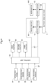
FIG. 4 is a control block diagram. -
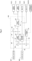
FIG. 5 is a flowchart illustrating control operations. -
FIG. 6 is a diagram showing a flow of power transmission according to an alternative embodiment. - An embodiment for carrying out the present invention will be described with reference to the drawings. In the following description, unless particularly specified otherwise, the arrow F shown in the drawings indicates the "forward direction", the arrow B indicates the "rearward direction", the arrow L indicates the "leftward direction", and the arrow R indicates the "rightward direction". The arrow U shown in the drawings indicates the "upward direction", and the arrow D indicates the "downward direction".
- A tractor as an example of a work vehicle according to the present invention will be described below. As shown in
FIG. 1 , the tractor includes left and rightfront wheels 10 and left and rightrear wheels 11 that constitute atravel device 1. The tractor includes abody frame 2 and adriving section 3. Thebody frame 2 is supported by the left and rightfront wheels 10 and the left and rightrear wheels 11. Thedriving section 3 is provided at a rear portion of the body. Apower transmission case 16 configured to transmit power to therear wheels 11 is provided below thedriving section 3. - The
driving section 3 includes aprotection frame 30, a driver'sseat 31, asteering wheel 32, and other operation tools. An operator can sit on the driver'sseat 31. The left and rightfront wheels 10 can be steered by operating thesteering wheel 32. The operator can perform various driving operations in thedriving section 3. - A
cover member 12 is provided forward of thedriving section 3. A large, high-voltage battery is provided inside thecover member 12. Thecover member 12 is configured to swing about an opening and closing axis Q extending in the left-right direction of the body. Thus, thecover member 12 can be opened and closed. While thecover member 12 is closed, thebattery 4 is covered by thecover member 12. - As shown in
FIG. 2 , the tractor includes a travel electric motor (hereinafter referred to as a "travel motor") M1 capable of driving thefront wheels 10 and therear wheels 11. Thebattery 4 supplies electric power to atravel inverter 14. Thetravel inverter 14 converts direct-current power supplied from thebattery 4 into alternating-current power, and supplies the alternating-current power to the travel motor M1. Thebattery 4 supplies high-voltage (e.g., several tens to several hundreds of volts) electric power to the travel motor M1 via an electricpower supply line 39. - The travel motor M1 is driven by the alternating-current power supplied from the
travel inverter 14. The power of the travel motor M1 is transmitted to therear wheels 11 via anoutput shaft 5 and a power transmission mechanism (not shown) contained in thepower transmission case 16. The power of the travel motor M1 is transmitted from thepower transmission case 16 to the fronts wheel 10 via a relaypower transmission shaft 6. - The tractor includes a power take-off
shaft 7 capable of outputting power to the outside of the body, and a work electric motor (hereinafter referred to as a "work motor") M2 capable of rotationally driving the power take-offshaft 7. Specifically, as shown inFIG. 2 , the tractor includes, as the power take-offshaft 7, amid PTO shaft 17 located at an intermediate position in the vehicle body in the front-rear direction, and arear PTO shaft 18 located at a rear portion of the vehicle body. The work motor M2 transmits power to themid PTO shaft 17 and therear PTO shaft 18. When a work device is connected to themid PTO shaft 17 or therear PTO shaft 18, the work device is driven by the rotational power of themid PTO shaft 17 or therear PTO shaft 18. For example, in the present embodiment, amowing device 19 is connected to themid PTO shaft 17 as shown inFIG. 2 . Themowing device 19 is driven by the rotational power of themid PTO shaft 17. Themowing device 19 is elevatably supported by thebody frame 2 via anelevation link mechanism 20. - The
rear PTO shaft 18 protrudes rearward from a rear portion of thepower transmission case 16. Although not shown, therear PTO shaft 18 supplies power to a rear-side work device (not shown) attached to a rear portion of the body. The rear-side work device is elevatably coupled to thepower transmission case 16 via a link mechanism. Alift arm 21 capable of raising and lowering the rear-side work device is provided above thepower transmission case 16. Thelift arm 21 is operated to vertically swing by operating ahydraulic cylinder 23 serving ashydraulic equipment 22. - The
lift arm 21 and theelevation link mechanism 20 configured to elevatably support themowing device 19 are interlocked with each other via a push-pull link 24. Accordingly, through extension and contraction of thehydraulic cylinder 23, themowing device 19 is operated to be raised and lowered in response to vertical swinging of thelift arm 21. - As shown in
FIG. 4 , thebattery 4 supplies electric power to awork inverter 15 via an electricpower supply line 39. Thework inverter 15 converts direct-current power supplied from thebattery 4 into alternating-current power, and supplies the alternating-current power to the work motor M2 via the electricpower supply line 39. Then, the work motor M2 is driven by the alternating-current power supplied from thework inverter 15. The power of the work motor M2 is transmitted to themid PTO shaft 17 and therear PTO shaft 18 via a branchingdevice 8. - The tractor includes a power-transmission-state switching mechanism DK capable of being switched between (i) an independent power transmission state in which output of the travel motor M1 is output to the
front wheels 10 and therear wheels 11 and in which output of the work motor M2 is output to the power take-offshaft 7, and (ii) a cooperative output power transmission state in which the travel motor M1 and the work motor M2 are capable of cooperatively outputting power to a drive target. - As shown in
FIG. 3 , the power-transmission-state switching mechanism DK includes a travelpower transmission section 40 configured to transmit power between the travel motor M1 and the front andrear wheels power transmission section 41 configured to transmit power between the work motor M2 and the power take-offshaft 7, and a relaypower transmission section 42 capable of transmitting power between an intermediate portion of the travelpower transmission section 40 and an intermediate portion of the workpower transmission section 41. - The power-transmission-state switching mechanism DK includes: a first clutch 43 serving as a travel clutch mechanism capable of being switched between a power transmission state in which power from the travel motor M1 is transmitted to the
front wheels 10 and therear wheels 11, and a disengaged state in which the power transmission is disabled; a second clutch 44 serving as a work clutch mechanism capable of being switched between a power transmission state in which power from the work motor M2 is transmitted to the power take-offshaft 7, and a disengaged state in which the power transmission is disabled; and a third clutch 45 serving as a relay clutch mechanism capable of being switched between a power transmission state in which power transmission performed by the relaypower transmission section 42 is enabled, and a disengaged state in which the power transmission is disabled. - The relay
power transmission section 42 is capable of transmitting power between a portion of the travelpower transmission section 40 that is located upstream of the first clutch 43 along a power transmission path, and a portion of the work power transmission section that is located upstream of the second clutch 44 along the power transmission path. The first clutch 43 is provided in the travelpower transmission section 40. The second clutch 44 is provided in the workpower transmission section 41. The third clutch 45 is provided at an intermediate portion of the relaypower transmission section 42 along the power transmission path. - More specifically, the travel
power transmission section 40 includes afirst output shaft 46 to which power of the travel motor M1 is output, a relaypower transmission shaft 47 to which power is transmitted from thefirst output shaft 46, afirst gear mechanism 48 configured to interlock thefirst output shaft 46 and the relaypower transmission shaft 47 with each other, and the first clutch 43 configured to enable and disable the power transmission performed via the relaypower transmission shaft 47. The relaypower transmission shaft 47 includes anextended shaft part 47a extending on a side opposite to the first clutch 43 relative to thefirst gear mechanism 48. - The work
power transmission section 41 includes asecond output shaft 49 to which power of the work motor M2 is output, and the second clutch 44 configured to enable and disable the power transmission performed via thesecond output shaft 49. - The relay
power transmission section 42 includes theextended shaft part 47a of the relaypower transmission shaft 47, asecond gear mechanism 50 located at a shaft end portion of theextended shaft part 47a of the relaypower transmission shaft 47, and the third clutch 45 located on theextended shaft part 47a at a position between thefirst gear mechanism 48 and thesecond gear mechanism 50 and configured to enable and disable the power transmission performed via the relaypower transmission section 42. - The
second gear mechanism 50 is interlocked in such a manner as to transmit power also to adrive shaft 52 of thehydraulic pump 51. Accordingly, thehydraulic pump 51 is driven in response to the work motor M2 being rotationally driven. The pressure oil supplied from thehydraulic pump 51 is supplied to thehydraulic equipment 22 such as thehydraulic cylinder 23. Thehydraulic equipment 22 includes equipment other than thehydraulic cylinder 23. - The tractor includes a
control unit 53 configured to control the switching of the power-transmission-state switching mechanism DK.
Specifically, the first clutch 43, the second clutch 44, and thethird clutch 45 of the power-transmission-state switching mechanism DK are configured to be solenoid operated and electrically switched. Also, as shown inFIG. 4 , the tractor includes thecontrol unit 53 configured to control the operation of the first clutch 43, the second clutch 44, and the third clutch 45. Thecontrol unit 53 controls the operation of the travel motor M1 and the work motor M2, in addition to the operation of the clutches. Thecontrol unit 53 controls the operation of the various parts in accordance with a preset control program. - Although not shown, the
operation panel 54 of thedriving section 3 includes an operation tool for performing various instruction operations, a meter panel that displays the traveling state and the work state of the vehicle body, and information (e.g., the charge amount and the temperature) about thebattery 4, and so forth. Theoperation panel 54 is connected to thecontrol unit 53. Various types of instruction information are input to thecontrol unit 53 by a driver operating the operation tool according to the work condition. - Although not shown, an
accelerator device 33 includes a lever configured to be swingably operated, and a potentiometer configured to be operated by swinging the lever. Theaccelerator device 33 is connected to a control device 34. Thecontrol unit 53 is configured to give instructions to thetravel inverter 14 according to an instruction from theaccelerator device 33. Thetravel inverter 14 is configured to, according to an instruction from thecontrol unit 53, control the output of the travel motor M1 by adjusting the electric power supplied from thebattery 4 to the travel motor M1. - The tractor includes an
axle rotation sensor 55 configured to detect the axle rotation speed (corresponding to the body traveling speed) when thefront wheels 10 and therear wheels 11 are driven to rotate, and aPTO rotation sensor 56 configured to detect the rotation speed of the power take-offshaft 7. Information on these speeds is input to thecontrol unit 53. - The tractor includes, in addition to the high-
voltage battery 4, an electric component battery (not shown) that supplies electric power to thecontrol unit 53 and various electric components electrically controlled by thecontrol unit 53. The electric component battery supplies low-voltage (12 volts) electric power in order to drive the electric components. Thecontrol unit 53 is connected to the electric components via low voltage signal lines 57. - Control operations performed by the
control unit 53 will be described below with reference to the flowchart shown inFIG. 5 . Based on instruction operations performed on theoperation panel 54 by the driver, thecontrol unit 53 controls the operation of the travel motor M1 and the work motor M2, and controls the switching of the power-transmission-state switching mechanism DK. - In response to a work traveling state being instructed via the operation panel 54 (step #1), the
control unit 53 causes the work device (mowing device 19) to operate while causing the vehicle body to travel. That is, in response to a work traveling state being instructed, thecontrol unit 53 switches the first clutch 43 and the second clutch 44 to a clutch-on state (power transmission state), and switches the third clutch 45 to a clutch-off state (disengaged state) (step #2). Then, thecontrol unit 53 causes the work motor M2 to operate such that the rotation speed of the power take-offshaft 7 detected by thePTO rotation sensor 56 reaches a set number of revolutions required for the work (step #3). Also, thecontrol unit 53 causes the travel motor M1 to operate such that an axle rotation speed (corresponding to the body traveling speed) detected by theaxle rotation sensor 55 reaches a rotation speed corresponding to a target speed set by the accelerator device 33 (step #4). The power transmission state of the power-transmission-state switching mechanism DK during the work travel corresponds to the independent power transmission state. - In response to an instruction to perform only work being given via the
operation panel 54, thecontrol unit 53 causes the work device (mowing device 19) to operate while traveling of the vehicle body is stopped. That is, in response to "work only" being instructed (step #1), thecontrol unit 53 switches the first clutch 43 and the third clutch 45 to the clutch-off state (disengaged state), and switches the second clutch 44 to the clutch-on state (power transmission state) (step #6). Then, thecontrol unit 53 causes the work motor M2 to operate such that the rotation speed of the power take-offshaft 7 detected by thePTO rotation sensor 56 reaches a set number of revolutions required for the work (step #7). - In response to detection of an excessive load applied to the work motor M2 (e.g., due to a significant reduction in the rotation speed of the power take-off
shaft 7 detected by thePTO rotation sensor 56 relative to the set number of revolutions) while the work motor M2 is operated (step #8), a high-load mode is set (step #9). - In response to a high-load mode being set, the
control unit 53 switches the third clutch 45 to the clutch-on state (power transmission state) (step #10), and further causes the travel motor M1 to operate (step #11). The target rotation speed of the travel motor M1 at this time is set to the set number of revolutions required for the work. In this manner, it is possible to cause the work motor M2 and the travel motor M1 to operate cooperatively to achieve a significant driving force, thus disentangling entangled blades of grass. - After the high-load mode has been set, the above-described cooperative operation is continued until the high-load state is cancelled (
steps # 5, #8 to #11). In response to cancellation of the high-load state, the setting of the high-load mode is cancelled (step #12), and thereafter only the work motor M2 is operated (steps # 6, #7, #8, #12). - The power transmission state of the power-transmission-state switching mechanism DK during "work only" corresponds to a second state of the cooperative output power transmission state. Note that possible cases where a high load is applied while the
mowing device 19 is mounted as the work device include a case where a significant load is applied as a result of long blades of grass being entangled inside themowing device 19 during traveling work, thus stopping the traveling. - In response to an instruction to perform only traveling being given via the
operation panel 54, thecontrol unit 53 causes the travel motor M1 to operate while the operation of the work device is stopped. That is, in response to "traveling only" being instructed (step #1), thecontrol unit 53 switches the second clutch 44 and the third clutch 45 to the clutch-off state (disengaged state), and switches the first clutch 43 to the clutch-on state (power transmission state) (step #14). Then, thecontrol unit 53 causes the travel motor M1 to operate such that the axle rotation speed (corresponding to the body traveling speed) detected by theaxle rotation sensor 55 reaches a rotation speed corresponding to the target traveling speed set by the accelerator device 33 (step #15). - In response to detection of an excessive load applied to the travel motor M1 (e.g., due to a significant reduction in the axle rotation speed detected by the axle rotation sensor relative to the rotation speed corresponding to the target traveling speed) while the travel motor M1 is operated, a high-load mode is set (
steps # 16, #17). - In response to the high-load mode being set, the
control unit 53 switches the third clutch 45 to the clutch-on state (power transmission state) (step #18), and further causes the work motor M2 to operate (step #19). The target rotation speed of the work motor M2 at this time is set to the rotation speed corresponding to the target traveling speed. In this manner, it is possible to cause the work motor M2 and the travel motor M1 to operate cooperatively to achieve a significant driving force, thus performing traveling smoothly. - After the high-load mode has been set, the above-described cooperative operation is continued until the high-load state is cancelled (
steps # 13, #16 to #19). In response to cancellation of the high-load state, the setting of the high-load mode is cancelled (step #20), and thereafter only the travel motor M1 is operated (steps # 14, #15, #16, #20). - The power transmission state of the power-transmission-state switching mechanism DK during "traveling only" corresponds to a first state of the cooperative output power transmission state. Note that possible cases where a high load is applied while "traveling only" is instructed include a case where the vehicle body travels to a different location after completing work travel at a work site, or before performing work, as well as a case where a wheel or wheels become stuck in a muddy place, and is thus subjected to a significant travel resistance by mud.
- Accordingly, the
control unit 53 is capable of switching, based on a switching instruction, the cooperative output power transmission state between the first state in which power is output to the travel device 1 (front wheels 10, rear wheels 11) as a drive target, and the second state in which power is output to the power take-offshaft 7 as a drive target. -
- (1) In the above embodiment, as shown in
FIG. 6 , thehydraulic pump 51 is driven by power from the work motor M2. However, in place of this configuration, it is possible to adopt a configuration including a dedicated hydraulic motor M3 for driving ahydraulic pump 51, separately from the work motor M2. - (2) The above embodiment adopts a configuration including one travel motor M1 and one work motor M2. However, it is possible to adopt a configuration including a plurality of travel motors M1, or a configuration including a plurality of work motors M2.
- (3) The above embodiment adopts a configuration in which the power-transmission-state switching mechanism DK includes the three
clutches power transmission section 42. However, in place of such a configuration, it is possible to adopt, for example, a configuration in which the independent power transmission state and the cooperative output power transmission state may be created with a planetary gear mechanism interposed between the travelpower transmission section 40 and the workpower transmission section 41. - (4) The above embodiment adopts a configuration including the
mid PTO shaft 17 and therear PTO shaft 18 as the power take-offshaft 7. In place of this configuration, it is possible to adopt configuration including only either themid PTO shaft 17 or therear PTO shaft 18, or a configuration including a PTO shaft different from themid PTO shaft 17 and therear PTO shaft 18. - (5) The above embodiment adopts a configuration in which the cooperative output power transmission state can be switched between the first state in which power is output to the travel device 1 (
front wheels 10, rear wheels 11), and the second state in which power is output to the power take-offshaft 7. However, the cooperative output power transmission state may only include a state in which power is output to the travel device 1 (front wheels 10, rear wheels 11), or the cooperative output power transmission state may only include a state in which power is output to the power take-offshaft 7. - (6) The present invention is applicable to various work vehicles such as a tractor, a ride-on lawn mower, and a carrier vehicle.
Claims (3)
- A work vehicle comprising:a travel device (10,11) supporting a body (2) of the work vehicle in such a manner as to enable the body to travel;a power take-off shaft (17,18) configured to output power out from the body;a travel electric motor (M1) configured to drive the travel device;a work electric motor (M2) configured to drive the power take-off shaft to rotate;a power-transmission-state switching mechanism (DK) configured to be switched between (i) an independent power transmission state in which output from the travel electric motor is output to the travel device and in which output from the work electric motor is output to the power take-off shaft, and (ii) a cooperative output power transmission state in which the travel electric motor and the work electric motor are capable of cooperatively outputting power to a drive target; anda control unit (53) configured to control switching of the power-transmission-state switching mechanism.
- The work vehicle according to claim 1, wherein:
the control unit (53) switches, based on a switching instruction, the cooperative output power transmission state between a first state in which power is output to the travel device as the drive target, and a second state in which power is output to the power take-off shaft as the drive target. - The work vehicle according to claim 1 or 2, wherein:
the power-transmission-state switching mechanism (DK) includes:a travel clutch mechanism (43) provided in a travel power transmission section (40) between the travel electric motor (M1) and the travel device (10,11), and configured to be switched between a power transmission state in which power from the travel electric motor is transmitted to the travel device, and a disengaged state in which the transmission of power from the travel electric motor to the travel device is disabled;a work clutch mechanism (44) provided in a work power transmission section (41) between the work electric motor and the power take-off shaft, and configured to be switched between a power transmission state in which power from the work electric motor is transmitted to the power take-off shaft, and a disengaged state in which the transmission of power from the work electric motor to the power take-off shaft is disabled;a relay power transmission section (42) configured to transmit power between a portion of the travel power transmission section that is located upstream of the travel clutch mechanism along a power transmission path, and a portion of the work power transmission section that is located upstream of the work clutch mechanism along the power transmission path; anda relay clutch mechanism (45) configured to be switched between a power transmission state in which power transmission by the relay power transmission section is enabled, and a disengaged state in which the power transmission by the relay power transmission section is disabled.
Applications Claiming Priority (1)
| Application Number | Priority Date | Filing Date | Title |
|---|---|---|---|
| JP2023000163A JP2024096587A (en) | 2023-01-04 | 2023-01-04 | Work Machine |
Publications (1)
| Publication Number | Publication Date |
|---|---|
| EP4397520A1 true EP4397520A1 (en) | 2024-07-10 |
Family
ID=89222289
Family Applications (1)
| Application Number | Title | Priority Date | Filing Date |
|---|---|---|---|
| EP23215999.6A Pending EP4397520A1 (en) | 2023-01-04 | 2023-12-12 | Work vehicle |
Country Status (3)
| Country | Link |
|---|---|
| US (1) | US12311769B2 (en) |
| EP (1) | EP4397520A1 (en) |
| JP (1) | JP2024096587A (en) |
Families Citing this family (4)
| Publication number | Priority date | Publication date | Assignee | Title |
|---|---|---|---|---|
| US12576720B2 (en) * | 2024-02-12 | 2026-03-17 | Dana Belgium | System and method for operating a vehicle with electric power take-off |
| EP4678437A1 (en) * | 2024-07-12 | 2026-01-14 | Deere & Company | Drive assembly, axle and working machine |
| EP4678448A1 (en) * | 2024-07-12 | 2026-01-14 | Deere & Company | Drive assembly, axle and working machine |
| JP2026060844A (en) * | 2024-09-27 | 2026-04-08 | トラクターズ アンド ファーム イクイップメント リミテッド | Independent power split transmission drivetrain and method for electric vehicles |
Citations (4)
| Publication number | Priority date | Publication date | Assignee | Title |
|---|---|---|---|---|
| CN109733174A (en) * | 2018-12-07 | 2019-05-10 | 江苏大学 | A control device for electric tractor dual-motor power confluence |
| JP2020108213A (en) | 2018-12-26 | 2020-07-09 | 株式会社クボタ | Electric work vehicle |
| DE102020208200A1 (en) * | 2020-07-01 | 2022-01-05 | Zf Friedrichshafen Ag | Power take-off arrangement |
| CN114635950A (en) * | 2020-12-16 | 2022-06-17 | 韩虎产业株式会社 | Transmission for electric automobile |
Family Cites Families (129)
| Publication number | Priority date | Publication date | Assignee | Title |
|---|---|---|---|---|
| US1055619A (en) * | 1912-04-27 | 1913-03-11 | William Dunn | Hydraulic transmission mechanism. |
| US1609833A (en) * | 1921-12-12 | 1926-12-07 | Universal Engineering Corp | Locomotive engine |
| US2031399A (en) * | 1934-02-16 | 1936-02-18 | Holice N White | Automobile power take-off mechanism |
| US4233858A (en) * | 1976-12-27 | 1980-11-18 | The Garrett Corporation | Flywheel drive system having a split electromechanical transmission |
| JPS6325421Y2 (en) * | 1980-04-03 | 1988-07-11 | ||
| JP2538356B2 (en) * | 1989-11-20 | 1996-09-25 | 株式会社神崎高級工機製作所 | Transmission system for self-propelled work vehicle |
| US5046306A (en) * | 1990-07-23 | 1991-09-10 | General Motors Corporation | Secondary oil system |
| JP3445339B2 (en) * | 1993-11-25 | 2003-09-08 | 株式会社 神崎高級工機製作所 | Four-wheel drive transmission for work vehicles |
| US5406778A (en) * | 1994-02-03 | 1995-04-18 | Ransomes America Corporation | Electric drive riding greens mower |
| JP3445391B2 (en) * | 1994-11-11 | 2003-09-08 | 株式会社 神崎高級工機製作所 | Tractor transmission device |
| US5873224A (en) * | 1995-09-07 | 1999-02-23 | Kubota Corporation | Power transmitting structure for a self-propelling vehicle having a working implement |
| US5557977A (en) * | 1995-11-06 | 1996-09-24 | Ford Motor Company | System for powering rotating vehicle accessories using transmission |
| US6048288A (en) * | 1997-11-18 | 2000-04-11 | Toyota Jidosha Kabushiki Kaisha | Power train system for a vehicle and method for operating same |
| US6109009A (en) * | 1998-01-16 | 2000-08-29 | Textron Inc. | Constant speed control for electric greens mower |
| EP1642487B1 (en) * | 2002-04-03 | 2007-10-24 | Kanzaki Kokyukoki MFG. Co., Ltd. | Pump unit and working vehicle |
| US7391129B2 (en) * | 2002-05-31 | 2008-06-24 | Ise Corporation | System and method for powering accessories in a hybrid vehicle |
| US7179188B2 (en) * | 2002-08-02 | 2007-02-20 | Norihiro Ishii | Transmission apparatus for a working vehicle |
| US6860358B1 (en) * | 2002-10-04 | 2005-03-01 | Hydro-Gear Limited Partnership | Utility vehicle having hydrostatic drive |
| US6953327B1 (en) * | 2003-03-11 | 2005-10-11 | Hydro-Gear Limited Partnership | Dual pump |
| DE10318070C5 (en) * | 2003-04-17 | 2022-06-23 | Volkswagen Ag | Device and method for lubricating and cooling gear drives |
| US6964631B2 (en) * | 2004-02-24 | 2005-11-15 | General Motors Corporation | Integrated electric motor-driven oil pump for automatic transmissions in hybrid applications |
| JP4208774B2 (en) * | 2004-06-24 | 2009-01-14 | 株式会社クボタ | Riding mower |
| US7421917B2 (en) * | 2004-06-25 | 2008-09-09 | Kubota Corporation | Tractor with a PTO apparatus |
| US20060059879A1 (en) * | 2004-09-20 | 2006-03-23 | Edmond Brian W | Multifunction electric tractor |
| TWI330218B (en) * | 2004-10-29 | 2010-09-11 | Tai Her Yang | Split serial-parallel hybrid dual-power drive system |
| JP2006321339A (en) * | 2005-05-18 | 2006-11-30 | Kanzaki Kokyukoki Mfg Co Ltd | Power transmission mechanism of hydraulic drive working vehicle |
| JP2007283986A (en) * | 2006-04-19 | 2007-11-01 | Kanzaki Kokyukoki Mfg Co Ltd | Hydraulic axle drive unit |
| JP2008157161A (en) * | 2006-12-26 | 2008-07-10 | Kanzaki Kokyukoki Mfg Co Ltd | Multi-pump unit and vehicle equipped with multi-pump unit |
| JP4311754B2 (en) * | 2007-06-21 | 2009-08-12 | 三菱電機株式会社 | Vehicle drive device |
| US7713157B2 (en) * | 2007-07-11 | 2010-05-11 | Eaton Corporation | Planetary gear controlled alternator |
| US7726275B2 (en) * | 2007-07-12 | 2010-06-01 | Ford Global Technologies, Llc | System and method for powering a mechanically driven accessory component in an automotive vehicle |
| US8818588B2 (en) * | 2007-07-12 | 2014-08-26 | Odyne Systems, Llc | Parallel hybrid drive system utilizing power take off connection as transfer for a secondary energy source |
| US9878616B2 (en) * | 2007-07-12 | 2018-01-30 | Power Technology Holdings Llc | Hybrid vehicle drive system and method using split shaft power take off |
| US20120207620A1 (en) * | 2007-07-12 | 2012-08-16 | Odyne Systems, LLC. | Hybrid vehicle drive system and method and idle reduction system and method |
| US8978798B2 (en) * | 2007-10-12 | 2015-03-17 | Odyne Systems, Llc | Hybrid vehicle drive system and method and idle reduction system and method |
| US7578116B1 (en) * | 2007-08-10 | 2009-08-25 | Richard D. Meyer | Battery-operated riding rotary mower |
| EP2188145B1 (en) * | 2007-09-11 | 2014-06-25 | Hydro-Gear Limited Partnership | Control systems and methods for electric drive utility vehicles |
| US8808124B2 (en) * | 2008-04-15 | 2014-08-19 | GM Global Technology Operations LLC | Belt alternator starter systems for hybrid vehicles |
| JP4707072B2 (en) * | 2008-05-23 | 2011-06-22 | 本田技研工業株式会社 | Power transmission device for vehicle |
| US9549504B2 (en) * | 2008-06-06 | 2017-01-24 | Kanzaki Kokyukoki Mfg. Co., Ltd. | Transaxle system for vehicle |
| WO2010048561A2 (en) * | 2008-10-23 | 2010-04-29 | Hydro-Gear Limited Partnership | Control systems and methods for electric motors of utility vehicles |
| US8511216B2 (en) * | 2009-03-30 | 2013-08-20 | Kanzaki Kokyukoki Mfg. Co., Ltd. | Hydraulic actuator unit |
| CN102362100B (en) * | 2009-09-25 | 2014-04-16 | 爱信艾达株式会社 | Drive device |
| CN102666169A (en) * | 2010-01-18 | 2012-09-12 | 日立建机株式会社 | Drive control device for working vehicle |
| US20110190083A1 (en) * | 2010-02-02 | 2011-08-04 | ALTe | Accessory drive system for a vehicle |
| JP5168598B2 (en) * | 2010-03-31 | 2013-03-21 | アイシン・エィ・ダブリュ株式会社 | Hybrid drive device |
| JP5365880B2 (en) * | 2010-06-08 | 2013-12-11 | アイシン・エィ・ダブリュ株式会社 | Vehicle drive device |
| US8649925B2 (en) * | 2010-08-30 | 2014-02-11 | Ford Global Technologies, Llc | Method and system for controlling operation of an electric oil pump in a hybrid electric vehicle (HEV) |
| US8322482B2 (en) * | 2010-09-27 | 2012-12-04 | Deere & Company | Tractor ground positioning system |
| US8689759B2 (en) * | 2010-10-01 | 2014-04-08 | GM Global Technology Operations LLC | Dual drive pump system using an engine starter motor |
| US8616310B2 (en) * | 2011-01-14 | 2013-12-31 | Gilbert T. Lopez | Apparatus for farming, gardening and landscaping |
| JP5297473B2 (en) * | 2011-02-04 | 2013-09-25 | アイシン・エィ・ダブリュ株式会社 | Vehicle drive device |
| US8905885B2 (en) * | 2011-02-04 | 2014-12-09 | Aisin Aw Co., Ltd. | Vehicle drive device |
| JP2012187025A (en) * | 2011-03-09 | 2012-10-04 | Kubota Corp | Riding working vehicle |
| WO2012140963A1 (en) * | 2011-04-13 | 2012-10-18 | 日産自動車株式会社 | Lubrication control device for in-wheel motor unit for vehicle |
| US9266423B2 (en) * | 2011-06-07 | 2016-02-23 | Honda Motor Co., Ltd. | Vehicle driving device |
| EP2731820B1 (en) * | 2011-07-14 | 2019-09-25 | Husqvarna Ab | Riding lawn mower including battery powered cutting system |
| JP5545413B2 (en) * | 2011-07-19 | 2014-07-09 | トヨタ自動車株式会社 | Lubricating device for hybrid vehicle power transmission device |
| JP2013053737A (en) * | 2011-09-06 | 2013-03-21 | Honda Motor Co Ltd | Supporting structure for planetary gear mechanism |
| WO2013080982A1 (en) * | 2011-12-01 | 2013-06-06 | 本田技研工業株式会社 | Power transmission device |
| US8784246B2 (en) * | 2011-12-14 | 2014-07-22 | Caterpillar Inc. | Series drivetrain with CVT output |
| US9638076B2 (en) * | 2011-12-24 | 2017-05-02 | Kawasaki Jukogyo Kabushiki Kaisha | Electric vehicle |
| JP5885534B2 (en) * | 2012-02-21 | 2016-03-15 | 本田技研工業株式会社 | Control system |
| EP2639128B1 (en) * | 2012-03-13 | 2023-09-06 | Kanzaki Kokyukoki Mfg. Co., Ltd. | Work vehicle |
| KR20140136992A (en) * | 2012-03-29 | 2014-12-01 | 이턴 코포레이션 | Electric energy generation using variable speed hybrid electric supercharger assembly |
| US9500197B2 (en) * | 2012-05-18 | 2016-11-22 | Gm Global Technology Operations, Llc | Pump assembly with multiple gear ratios |
| WO2014018503A1 (en) * | 2012-07-25 | 2014-01-30 | Fisker Automotive, Inc. | All wheel drive system for hybrid vehicle |
| DE102013013623B4 (en) * | 2012-08-29 | 2022-06-30 | Kanzaki Kokyukoki Mfg. Co., Ltd. | Motor control system for an electric motor driven vehicle |
| JP6192919B2 (en) * | 2012-11-02 | 2017-09-06 | Ntn株式会社 | In-wheel motor drive device |
| US9033074B1 (en) * | 2012-11-19 | 2015-05-19 | Chris Gates | Coupler with movable shaft |
| JP5790630B2 (en) * | 2012-12-05 | 2015-10-07 | トヨタ自動車株式会社 | Lubricating oil supply structure |
| JP5741563B2 (en) * | 2012-12-06 | 2015-07-01 | トヨタ自動車株式会社 | Power transmission device |
| US9114798B1 (en) * | 2012-12-12 | 2015-08-25 | Hydro-Gear Limited Partnership | Electric actuator for drive apparatus |
| US8939240B2 (en) * | 2013-03-01 | 2015-01-27 | Paccar Inc | Engine accessory drive system |
| US9872438B2 (en) * | 2013-03-15 | 2018-01-23 | Mtd Products Inc | Battery-electric and internal-combustion engine assist hybrid propulsion and implement drive work systems |
| US9487086B2 (en) * | 2013-04-02 | 2016-11-08 | Parker-Hannifin Corporation | Auxiliary modules mounted on a vehicle |
| SE538232C2 (en) * | 2013-05-08 | 2016-04-12 | BAE Systems Hägglunds Aktiebolag | Drive unit for tracked vehicles and vehicles equipped with drive unit |
| SE540219C2 (en) * | 2013-05-21 | 2018-05-02 | Scania Cv Ab | Power take-off, vehicles with such a power take-off and an intermediate part for such a power take-off |
| FR3008038B1 (en) * | 2013-07-02 | 2016-12-02 | Technoboost | POWER UNIT FOR A HYDRID HYDRAULIC VEHICLE, COMPRISING AN ELECTRIC MACHINE |
| JP5705928B2 (en) * | 2013-08-08 | 2015-04-22 | 株式会社小松製作所 | Wheel loader |
| CN106061784B (en) * | 2013-11-18 | 2019-07-19 | 电力科技控股有限责任公司 | Hybrid vehicle drive system and method using split shaft PTO |
| JP6182438B2 (en) * | 2013-11-26 | 2017-08-16 | アイシン・エィ・ダブリュ株式会社 | Vehicle drive transmission device |
| DE102013017976A1 (en) * | 2013-11-29 | 2015-06-03 | Fte Automotive Gmbh | Electric motor driven liquid pump, in particular for forced lubrication of a manual transmission for motor vehicles |
| MY188847A (en) * | 2013-12-02 | 2022-01-09 | Honda Motor Co Ltd | Vehicle |
| JP6265726B2 (en) * | 2013-12-16 | 2018-01-24 | 株式会社小松製作所 | Work vehicle and control method of work vehicle |
| JP6364194B2 (en) * | 2014-01-29 | 2018-07-25 | 株式会社小松製作所 | Work vehicle and control method thereof |
| GB2523765B (en) * | 2014-03-04 | 2016-09-28 | Johnston Sweepers Ltd | Powertrain for a road cleaning vehicle |
| US9499199B1 (en) * | 2014-04-23 | 2016-11-22 | Hydro-Gear Limited Partnership | Hybrid vehicle |
| US9671016B2 (en) * | 2014-06-10 | 2017-06-06 | Honda Motor Co., Ltd. | Power plant |
| US9156348B1 (en) * | 2014-07-17 | 2015-10-13 | GM Global Technology Operations LLC | Two axis electric drive |
| US9145054B1 (en) * | 2014-10-20 | 2015-09-29 | Power Solutions International, Inc. | Modular power take-off assembly |
| US20160145833A1 (en) * | 2014-11-21 | 2016-05-26 | Caterpillar Global Mining Llc | System and method for controlling power in machine having hydraulic devices |
| JP2016130115A (en) * | 2015-01-15 | 2016-07-21 | トヨタ自動車株式会社 | Hybrid vehicle drive control device |
| US11701959B2 (en) * | 2015-02-17 | 2023-07-18 | Oshkosh Corporation | Inline electromechanical variable transmission system |
| KR20230048154A (en) * | 2015-05-01 | 2023-04-10 | 블랙번 에너지, 인크. | Method and system for auxiliary power generation |
| US10358040B1 (en) * | 2015-06-01 | 2019-07-23 | Hydro-Gear Limited Partnership | Drive assembly and system for utility vehicle |
| US10106027B1 (en) * | 2015-06-01 | 2018-10-23 | Hydro-Gear Limited Partnership | Generator/cooling assembly and system for utility vehicle |
| EP3333462B1 (en) * | 2015-08-07 | 2021-03-24 | Yanmar Power Technology Co., Ltd. | Work vehicle |
| JP6314947B2 (en) * | 2015-10-02 | 2018-04-25 | トヨタ自動車株式会社 | Power transmission device cooling structure |
| CN107303814A (en) * | 2016-04-18 | 2017-10-31 | 深圳市沃特玛电池有限公司 | A kind of electrical vehicular power train assembly |
| JP6696857B2 (en) * | 2016-08-12 | 2020-05-20 | トヨタ自動車株式会社 | Lubrication device for vehicle gear |
| US10099552B2 (en) * | 2016-09-30 | 2018-10-16 | Deere & Company | Hydraulic-electric drive arrangement for work vehicles |
| JP6477656B2 (en) * | 2016-10-14 | 2019-03-06 | トヨタ自動車株式会社 | Oil passage structure of power transmission device |
| JP6423403B2 (en) * | 2016-10-14 | 2018-11-14 | トヨタ自動車株式会社 | Oil passage structure of power transmission device |
| JP6545217B2 (en) * | 2017-03-24 | 2019-07-17 | 本田技研工業株式会社 | Lubricating fluid supply structure of power transmission device |
| JP6680263B2 (en) * | 2017-05-19 | 2020-04-15 | トヨタ自動車株式会社 | Hybrid vehicle drive |
| JP6809393B2 (en) * | 2017-06-20 | 2021-01-06 | トヨタ自動車株式会社 | Lubrication device for vehicle power transmission device |
| US10781910B2 (en) * | 2017-08-03 | 2020-09-22 | Power Technology Holdings Llc | PTO lubrication system for hybrid vehicles |
| JP6338003B1 (en) * | 2017-09-27 | 2018-06-06 | トヨタ自動車株式会社 | Electric car |
| JP6811698B2 (en) * | 2017-11-21 | 2021-01-13 | 株式会社クボタ | Work vehicle and work vehicle management system |
| CN110739804B (en) * | 2018-07-18 | 2022-04-12 | 株式会社爱信 | Cooling structure of rotating electrical machine and drive device for vehicle |
| JP7107565B2 (en) * | 2018-10-22 | 2022-07-27 | 株式会社 神崎高級工機製作所 | Mobile drive unit and mobile |
| JP6996474B2 (en) * | 2018-10-31 | 2022-01-17 | トヨタ自動車株式会社 | Lubrication device for power transmission device |
| US10948070B2 (en) * | 2018-11-13 | 2021-03-16 | Deere & Company | Electric machine lubrication system |
| JP7052746B2 (en) * | 2019-01-25 | 2022-04-12 | トヨタ自動車株式会社 | Vehicle power transmission device |
| JP7111006B2 (en) * | 2019-01-25 | 2022-08-02 | トヨタ自動車株式会社 | vehicle power transmission |
| US11084369B2 (en) * | 2019-02-26 | 2021-08-10 | Deere & Company | Hybrid transmission module for work vehicles |
| JP7172762B2 (en) * | 2019-03-13 | 2022-11-16 | トヨタ自動車株式会社 | Control device for vehicle oil supply device |
| US10690234B1 (en) * | 2019-03-14 | 2020-06-23 | Proterra Inc. | Electric vehicle powertrain |
| JP7151632B2 (en) * | 2019-06-11 | 2022-10-12 | トヨタ自動車株式会社 | hybrid vehicle |
| JP7224245B2 (en) * | 2019-06-24 | 2023-02-17 | 株式会社クボタ | electric work vehicle |
| JP7246264B2 (en) * | 2019-06-24 | 2023-03-27 | 株式会社クボタ | electric work vehicle |
| US10989297B2 (en) * | 2019-07-19 | 2021-04-27 | Ford Global Technologies, Llc | Electric powertrain with sun bearing |
| JP7132191B2 (en) * | 2019-08-08 | 2022-09-06 | ヤンマーパワーテクノロジー株式会社 | Automated driving system for work vehicles |
| EP4567279A3 (en) * | 2019-10-11 | 2025-11-12 | Oshkosh Corporation | Operational modes for hybrid fire fighting vehicle |
| EP4077014A1 (en) * | 2019-12-19 | 2022-10-26 | AGCO International GmbH | Method of operating an agricultural vehicle and a transmission arrangement for an agricultural vehicle |
| JP7671157B2 (en) * | 2021-03-08 | 2025-05-01 | ニデック株式会社 | Drive unit |
| US11754169B1 (en) * | 2022-07-07 | 2023-09-12 | Ford Global Technologies, Llc | Lubrication and cooling oil distribution system for a vehicle transaxle |
| JP2024096596A (en) * | 2023-01-04 | 2024-07-17 | 株式会社クボタ | Electric work vehicle |
-
2023
- 2023-01-04 JP JP2023000163A patent/JP2024096587A/en active Pending
- 2023-12-12 EP EP23215999.6A patent/EP4397520A1/en active Pending
- 2023-12-14 US US18/540,126 patent/US12311769B2/en active Active
Patent Citations (4)
| Publication number | Priority date | Publication date | Assignee | Title |
|---|---|---|---|---|
| CN109733174A (en) * | 2018-12-07 | 2019-05-10 | 江苏大学 | A control device for electric tractor dual-motor power confluence |
| JP2020108213A (en) | 2018-12-26 | 2020-07-09 | 株式会社クボタ | Electric work vehicle |
| DE102020208200A1 (en) * | 2020-07-01 | 2022-01-05 | Zf Friedrichshafen Ag | Power take-off arrangement |
| CN114635950A (en) * | 2020-12-16 | 2022-06-17 | 韩虎产业株式会社 | Transmission for electric automobile |
Also Published As
| Publication number | Publication date |
|---|---|
| US12311769B2 (en) | 2025-05-27 |
| US20240217343A1 (en) | 2024-07-04 |
| JP2024096587A (en) | 2024-07-17 |
Similar Documents
| Publication | Publication Date | Title |
|---|---|---|
| US12311769B2 (en) | Work vehicle | |
| EP3777507B1 (en) | Work vehicle and grass mowing machine | |
| US10639983B2 (en) | Work vehicle | |
| EP3686353B1 (en) | Electric work vehicle | |
| US20240317049A1 (en) | Electric work vehicle | |
| US20240217349A1 (en) | Electric Work Vehicle | |
| US12139026B2 (en) | Work vehicle | |
| KR101324013B1 (en) | Electric drive type agriculture vehicles | |
| EP3476643B1 (en) | Work machine | |
| US20250229645A1 (en) | Electric work vehicle | |
| JP2023097970A (en) | electric work vehicle | |
| EP4516565A1 (en) | Electric work vehicle | |
| EP4344922A1 (en) | Work vehicle | |
| US12565093B2 (en) | Inverter arrangement for an electric work vehicle | |
| WO2023119888A1 (en) | Electric work vehicle | |
| JP7507742B2 (en) | Electric work vehicle | |
| JP2024025397A (en) | Charging system and charging method | |
| JP2021004586A (en) | Work vehicle | |
| WO2023127363A1 (en) | Electric work vehicle | |
| JP4589072B2 (en) | Three-wheel management machine | |
| JP2024011605A (en) | work vehicle | |
| JP4825411B2 (en) | Three-wheel management machine | |
| WO2021176266A1 (en) | Electrically powered, universal accessory drive |
Legal Events
| Date | Code | Title | Description |
|---|---|---|---|
| PUAI | Public reference made under article 153(3) epc to a published international application that has entered the european phase |
Free format text: ORIGINAL CODE: 0009012 |
|
| STAA | Information on the status of an ep patent application or granted ep patent |
Free format text: STATUS: REQUEST FOR EXAMINATION WAS MADE |
|
| 17P | Request for examination filed |
Effective date: 20231212 |
|
| AK | Designated contracting states |
Kind code of ref document: A1 Designated state(s): AL AT BE BG CH CY CZ DE DK EE ES FI FR GB GR HR HU IE IS IT LI LT LU LV MC ME MK MT NL NO PL PT RO RS SE SI SK SM TR |
|
| GRAP | Despatch of communication of intention to grant a patent |
Free format text: ORIGINAL CODE: EPIDOSNIGR1 |
|
| STAA | Information on the status of an ep patent application or granted ep patent |
Free format text: STATUS: GRANT OF PATENT IS INTENDED |
|
| INTG | Intention to grant announced |
Effective date: 20260410 |