EP4397496A1 - Liquid supply device, liquid discharge system, printing system, and liquid circulation method - Google Patents
Liquid supply device, liquid discharge system, printing system, and liquid circulation method Download PDFInfo
- Publication number
- EP4397496A1 EP4397496A1 EP22863993.6A EP22863993A EP4397496A1 EP 4397496 A1 EP4397496 A1 EP 4397496A1 EP 22863993 A EP22863993 A EP 22863993A EP 4397496 A1 EP4397496 A1 EP 4397496A1
- Authority
- EP
- European Patent Office
- Prior art keywords
- liquid
- ink
- flow passage
- case
- circulation
- Prior art date
- Legal status (The legal status is an assumption and is not a legal conclusion. Google has not performed a legal analysis and makes no representation as to the accuracy of the status listed.)
- Pending
Links
- 239000007788 liquid Substances 0.000 title claims abstract description 360
- 238000007639 printing Methods 0.000 title claims abstract description 110
- 238000000034 method Methods 0.000 title claims abstract description 49
- 239000002245 particle Substances 0.000 claims abstract description 106
- 238000004062 sedimentation Methods 0.000 claims abstract description 42
- 239000002904 solvent Substances 0.000 claims abstract description 33
- 239000000049 pigment Substances 0.000 claims description 44
- GWEVSGVZZGPLCZ-UHFFFAOYSA-N Titan oxide Chemical compound O=[Ti]=O GWEVSGVZZGPLCZ-UHFFFAOYSA-N 0.000 claims description 12
- OGIDPMRJRNCKJF-UHFFFAOYSA-N titanium oxide Inorganic materials [Ti]=O OGIDPMRJRNCKJF-UHFFFAOYSA-N 0.000 claims description 12
- 238000001914 filtration Methods 0.000 claims description 4
- 239000000976 ink Substances 0.000 description 579
- 238000011084 recovery Methods 0.000 description 57
- 238000004891 communication Methods 0.000 description 34
- 238000001035 drying Methods 0.000 description 30
- 238000000576 coating method Methods 0.000 description 26
- 239000011248 coating agent Substances 0.000 description 23
- 238000011156 evaluation Methods 0.000 description 20
- 238000012423 maintenance Methods 0.000 description 19
- 238000010586 diagram Methods 0.000 description 18
- 238000004804 winding Methods 0.000 description 17
- 230000006870 function Effects 0.000 description 15
- 238000004140 cleaning Methods 0.000 description 14
- 238000012545 processing Methods 0.000 description 14
- 241001362551 Samba Species 0.000 description 12
- 238000002474 experimental method Methods 0.000 description 11
- 230000008859 change Effects 0.000 description 10
- 230000008569 process Effects 0.000 description 10
- 230000004044 response Effects 0.000 description 10
- 238000003860 storage Methods 0.000 description 10
- 230000002950 deficient Effects 0.000 description 9
- 230000007246 mechanism Effects 0.000 description 8
- 238000004220 aggregation Methods 0.000 description 7
- 230000002776 aggregation Effects 0.000 description 7
- 230000000694 effects Effects 0.000 description 6
- 238000003384 imaging method Methods 0.000 description 6
- 238000012360 testing method Methods 0.000 description 6
- 238000012937 correction Methods 0.000 description 5
- 239000000463 material Substances 0.000 description 5
- 238000003825 pressing Methods 0.000 description 5
- 239000004065 semiconductor Substances 0.000 description 5
- 239000003086 colorant Substances 0.000 description 4
- 238000001514 detection method Methods 0.000 description 4
- 238000007641 inkjet printing Methods 0.000 description 4
- 230000002093 peripheral effect Effects 0.000 description 4
- 238000004904 shortening Methods 0.000 description 4
- 239000000758 substrate Substances 0.000 description 4
- 239000010410 layer Substances 0.000 description 3
- 239000011159 matrix material Substances 0.000 description 3
- 230000005499 meniscus Effects 0.000 description 3
- 230000003020 moisturizing effect Effects 0.000 description 3
- 239000011347 resin Substances 0.000 description 3
- 229920005989 resin Polymers 0.000 description 3
- 238000007761 roller coating Methods 0.000 description 3
- 239000007787 solid Substances 0.000 description 3
- 239000012463 white pigment Substances 0.000 description 3
- 230000001133 acceleration Effects 0.000 description 2
- 239000012790 adhesive layer Substances 0.000 description 2
- 230000002411 adverse Effects 0.000 description 2
- 230000003139 buffering effect Effects 0.000 description 2
- 238000004519 manufacturing process Methods 0.000 description 2
- 229910052751 metal Inorganic materials 0.000 description 2
- 239000002184 metal Substances 0.000 description 2
- 239000002923 metal particle Substances 0.000 description 2
- 238000012986 modification Methods 0.000 description 2
- 230000004048 modification Effects 0.000 description 2
- XLYOFNOQVPJJNP-UHFFFAOYSA-N water Substances O XLYOFNOQVPJJNP-UHFFFAOYSA-N 0.000 description 2
- RYGMFSIKBFXOCR-UHFFFAOYSA-N Copper Chemical compound [Cu] RYGMFSIKBFXOCR-UHFFFAOYSA-N 0.000 description 1
- XFXPMWWXUTWYJX-UHFFFAOYSA-N Cyanide Chemical compound N#[C-] XFXPMWWXUTWYJX-UHFFFAOYSA-N 0.000 description 1
- XUIMIQQOPSSXEZ-UHFFFAOYSA-N Silicon Chemical compound [Si] XUIMIQQOPSSXEZ-UHFFFAOYSA-N 0.000 description 1
- BQCADISMDOOEFD-UHFFFAOYSA-N Silver Chemical compound [Ag] BQCADISMDOOEFD-UHFFFAOYSA-N 0.000 description 1
- 230000002159 abnormal effect Effects 0.000 description 1
- 238000004458 analytical method Methods 0.000 description 1
- 238000007664 blowing Methods 0.000 description 1
- 229920002678 cellulose Polymers 0.000 description 1
- 239000001913 cellulose Substances 0.000 description 1
- 238000004040 coloring Methods 0.000 description 1
- 230000000295 complement effect Effects 0.000 description 1
- 239000000470 constituent Substances 0.000 description 1
- 229910052802 copper Inorganic materials 0.000 description 1
- 239000010949 copper Substances 0.000 description 1
- 230000006866 deterioration Effects 0.000 description 1
- 238000009826 distribution Methods 0.000 description 1
- 238000009429 electrical wiring Methods 0.000 description 1
- 238000005401 electroluminescence Methods 0.000 description 1
- 230000007613 environmental effect Effects 0.000 description 1
- 239000004744 fabric Substances 0.000 description 1
- PCHJSUWPFVWCPO-UHFFFAOYSA-N gold Chemical compound [Au] PCHJSUWPFVWCPO-UHFFFAOYSA-N 0.000 description 1
- 229910052737 gold Inorganic materials 0.000 description 1
- 239000010931 gold Substances 0.000 description 1
- 239000004973 liquid crystal related substance Substances 0.000 description 1
- 229910044991 metal oxide Inorganic materials 0.000 description 1
- 150000004706 metal oxides Chemical class 0.000 description 1
- 238000007645 offset printing Methods 0.000 description 1
- 239000002244 precipitate Substances 0.000 description 1
- 238000001556 precipitation Methods 0.000 description 1
- 238000010926 purge Methods 0.000 description 1
- 239000005871 repellent Substances 0.000 description 1
- 238000005096 rolling process Methods 0.000 description 1
- 238000000790 scattering method Methods 0.000 description 1
- 229910052710 silicon Inorganic materials 0.000 description 1
- 239000010703 silicon Substances 0.000 description 1
- 229910052709 silver Inorganic materials 0.000 description 1
- 239000004332 silver Substances 0.000 description 1
- 230000001629 suppression Effects 0.000 description 1
- 230000008719 thickening Effects 0.000 description 1
- 238000011144 upstream manufacturing Methods 0.000 description 1
Images






Classifications
-
- B—PERFORMING OPERATIONS; TRANSPORTING
- B41—PRINTING; LINING MACHINES; TYPEWRITERS; STAMPS
- B41J—TYPEWRITERS; SELECTIVE PRINTING MECHANISMS, i.e. MECHANISMS PRINTING OTHERWISE THAN FROM A FORME; CORRECTION OF TYPOGRAPHICAL ERRORS
- B41J2/00—Typewriters or selective printing mechanisms characterised by the printing or marking process for which they are designed
- B41J2/005—Typewriters or selective printing mechanisms characterised by the printing or marking process for which they are designed characterised by bringing liquid or particles selectively into contact with a printing material
- B41J2/01—Ink jet
- B41J2/21—Ink jet for multi-colour printing
- B41J2/2107—Ink jet for multi-colour printing characterised by the ink properties
- B41J2/2114—Ejecting specialized liquids, e.g. transparent or processing liquids
- B41J2/2117—Ejecting white liquids
-
- B—PERFORMING OPERATIONS; TRANSPORTING
- B41—PRINTING; LINING MACHINES; TYPEWRITERS; STAMPS
- B41J—TYPEWRITERS; SELECTIVE PRINTING MECHANISMS, i.e. MECHANISMS PRINTING OTHERWISE THAN FROM A FORME; CORRECTION OF TYPOGRAPHICAL ERRORS
- B41J2/00—Typewriters or selective printing mechanisms characterised by the printing or marking process for which they are designed
- B41J2/005—Typewriters or selective printing mechanisms characterised by the printing or marking process for which they are designed characterised by bringing liquid or particles selectively into contact with a printing material
- B41J2/01—Ink jet
-
- B—PERFORMING OPERATIONS; TRANSPORTING
- B41—PRINTING; LINING MACHINES; TYPEWRITERS; STAMPS
- B41J—TYPEWRITERS; SELECTIVE PRINTING MECHANISMS, i.e. MECHANISMS PRINTING OTHERWISE THAN FROM A FORME; CORRECTION OF TYPOGRAPHICAL ERRORS
- B41J2/00—Typewriters or selective printing mechanisms characterised by the printing or marking process for which they are designed
- B41J2/005—Typewriters or selective printing mechanisms characterised by the printing or marking process for which they are designed characterised by bringing liquid or particles selectively into contact with a printing material
- B41J2/01—Ink jet
- B41J2/135—Nozzles
- B41J2/165—Prevention or detection of nozzle clogging, e.g. cleaning, capping or moistening for nozzles
- B41J2/16517—Cleaning of print head nozzles
-
- B—PERFORMING OPERATIONS; TRANSPORTING
- B41—PRINTING; LINING MACHINES; TYPEWRITERS; STAMPS
- B41J—TYPEWRITERS; SELECTIVE PRINTING MECHANISMS, i.e. MECHANISMS PRINTING OTHERWISE THAN FROM A FORME; CORRECTION OF TYPOGRAPHICAL ERRORS
- B41J2/00—Typewriters or selective printing mechanisms characterised by the printing or marking process for which they are designed
- B41J2/005—Typewriters or selective printing mechanisms characterised by the printing or marking process for which they are designed characterised by bringing liquid or particles selectively into contact with a printing material
- B41J2/01—Ink jet
- B41J2/135—Nozzles
- B41J2/165—Prevention or detection of nozzle clogging, e.g. cleaning, capping or moistening for nozzles
- B41J2/16517—Cleaning of print head nozzles
- B41J2/16535—Cleaning of print head nozzles using wiping constructions
-
- B—PERFORMING OPERATIONS; TRANSPORTING
- B41—PRINTING; LINING MACHINES; TYPEWRITERS; STAMPS
- B41J—TYPEWRITERS; SELECTIVE PRINTING MECHANISMS, i.e. MECHANISMS PRINTING OTHERWISE THAN FROM A FORME; CORRECTION OF TYPOGRAPHICAL ERRORS
- B41J2/00—Typewriters or selective printing mechanisms characterised by the printing or marking process for which they are designed
- B41J2/005—Typewriters or selective printing mechanisms characterised by the printing or marking process for which they are designed characterised by bringing liquid or particles selectively into contact with a printing material
- B41J2/01—Ink jet
- B41J2/135—Nozzles
- B41J2/165—Prevention or detection of nozzle clogging, e.g. cleaning, capping or moistening for nozzles
- B41J2/16517—Cleaning of print head nozzles
- B41J2/16535—Cleaning of print head nozzles using wiping constructions
- B41J2/16538—Cleaning of print head nozzles using wiping constructions with brushes or wiper blades perpendicular to the nozzle plate
-
- B—PERFORMING OPERATIONS; TRANSPORTING
- B41—PRINTING; LINING MACHINES; TYPEWRITERS; STAMPS
- B41J—TYPEWRITERS; SELECTIVE PRINTING MECHANISMS, i.e. MECHANISMS PRINTING OTHERWISE THAN FROM A FORME; CORRECTION OF TYPOGRAPHICAL ERRORS
- B41J2/00—Typewriters or selective printing mechanisms characterised by the printing or marking process for which they are designed
- B41J2/005—Typewriters or selective printing mechanisms characterised by the printing or marking process for which they are designed characterised by bringing liquid or particles selectively into contact with a printing material
- B41J2/01—Ink jet
- B41J2/135—Nozzles
- B41J2/165—Prevention or detection of nozzle clogging, e.g. cleaning, capping or moistening for nozzles
- B41J2/16585—Prevention or detection of nozzle clogging, e.g. cleaning, capping or moistening for nozzles for paper-width or non-reciprocating print heads
- B41J2/16588—Print heads movable towards the cleaning unit
-
- B—PERFORMING OPERATIONS; TRANSPORTING
- B41—PRINTING; LINING MACHINES; TYPEWRITERS; STAMPS
- B41J—TYPEWRITERS; SELECTIVE PRINTING MECHANISMS, i.e. MECHANISMS PRINTING OTHERWISE THAN FROM A FORME; CORRECTION OF TYPOGRAPHICAL ERRORS
- B41J2/00—Typewriters or selective printing mechanisms characterised by the printing or marking process for which they are designed
- B41J2/005—Typewriters or selective printing mechanisms characterised by the printing or marking process for which they are designed characterised by bringing liquid or particles selectively into contact with a printing material
- B41J2/01—Ink jet
- B41J2/17—Ink jet characterised by ink handling
- B41J2/175—Ink supply systems ; Circuit parts therefor
- B41J2/17563—Ink filters
-
- C—CHEMISTRY; METALLURGY
- C09—DYES; PAINTS; POLISHES; NATURAL RESINS; ADHESIVES; COMPOSITIONS NOT OTHERWISE PROVIDED FOR; APPLICATIONS OF MATERIALS NOT OTHERWISE PROVIDED FOR
- C09D—COATING COMPOSITIONS, e.g. PAINTS, VARNISHES OR LACQUERS; FILLING PASTES; CHEMICAL PAINT OR INK REMOVERS; INKS; CORRECTING FLUIDS; WOODSTAINS; PASTES OR SOLIDS FOR COLOURING OR PRINTING; USE OF MATERIALS THEREFOR
- C09D11/00—Inks
- C09D11/30—Inkjet printing inks
- C09D11/32—Inkjet printing inks characterised by colouring agents
- C09D11/322—Pigment inks
-
- B—PERFORMING OPERATIONS; TRANSPORTING
- B41—PRINTING; LINING MACHINES; TYPEWRITERS; STAMPS
- B41J—TYPEWRITERS; SELECTIVE PRINTING MECHANISMS, i.e. MECHANISMS PRINTING OTHERWISE THAN FROM A FORME; CORRECTION OF TYPOGRAPHICAL ERRORS
- B41J2/00—Typewriters or selective printing mechanisms characterised by the printing or marking process for which they are designed
- B41J2/005—Typewriters or selective printing mechanisms characterised by the printing or marking process for which they are designed characterised by bringing liquid or particles selectively into contact with a printing material
- B41J2/01—Ink jet
- B41J2/015—Ink jet characterised by the jet generation process
- B41J2/04—Ink jet characterised by the jet generation process generating single droplets or particles on demand
- B41J2/045—Ink jet characterised by the jet generation process generating single droplets or particles on demand by pressure, e.g. electromechanical transducers
- B41J2/04501—Control methods or devices therefor, e.g. driver circuits, control circuits
- B41J2/04581—Control methods or devices therefor, e.g. driver circuits, control circuits controlling heads based on piezoelectric elements
-
- B—PERFORMING OPERATIONS; TRANSPORTING
- B41—PRINTING; LINING MACHINES; TYPEWRITERS; STAMPS
- B41J—TYPEWRITERS; SELECTIVE PRINTING MECHANISMS, i.e. MECHANISMS PRINTING OTHERWISE THAN FROM A FORME; CORRECTION OF TYPOGRAPHICAL ERRORS
- B41J2/00—Typewriters or selective printing mechanisms characterised by the printing or marking process for which they are designed
- B41J2/005—Typewriters or selective printing mechanisms characterised by the printing or marking process for which they are designed characterised by bringing liquid or particles selectively into contact with a printing material
- B41J2/01—Ink jet
- B41J2/17—Ink jet characterised by ink handling
- B41J2/18—Ink recirculation systems
-
- B—PERFORMING OPERATIONS; TRANSPORTING
- B41—PRINTING; LINING MACHINES; TYPEWRITERS; STAMPS
- B41J—TYPEWRITERS; SELECTIVE PRINTING MECHANISMS, i.e. MECHANISMS PRINTING OTHERWISE THAN FROM A FORME; CORRECTION OF TYPOGRAPHICAL ERRORS
- B41J2/00—Typewriters or selective printing mechanisms characterised by the printing or marking process for which they are designed
- B41J2/005—Typewriters or selective printing mechanisms characterised by the printing or marking process for which they are designed characterised by bringing liquid or particles selectively into contact with a printing material
- B41J2/01—Ink jet
- B41J2/135—Nozzles
- B41J2/165—Prevention or detection of nozzle clogging, e.g. cleaning, capping or moistening for nozzles
- B41J2/16517—Cleaning of print head nozzles
- B41J2/16535—Cleaning of print head nozzles using wiping constructions
- B41J2002/1655—Cleaning of print head nozzles using wiping constructions with wiping surface parallel with nozzle plate and mounted on reels, e.g. cleaning ribbon cassettes
-
- B—PERFORMING OPERATIONS; TRANSPORTING
- B41—PRINTING; LINING MACHINES; TYPEWRITERS; STAMPS
- B41J—TYPEWRITERS; SELECTIVE PRINTING MECHANISMS, i.e. MECHANISMS PRINTING OTHERWISE THAN FROM A FORME; CORRECTION OF TYPOGRAPHICAL ERRORS
- B41J25/00—Actions or mechanisms not otherwise provided for
- B41J2025/008—Actions or mechanisms not otherwise provided for comprising a plurality of print heads placed around a drum
-
- C—CHEMISTRY; METALLURGY
- C09—DYES; PAINTS; POLISHES; NATURAL RESINS; ADHESIVES; COMPOSITIONS NOT OTHERWISE PROVIDED FOR; APPLICATIONS OF MATERIALS NOT OTHERWISE PROVIDED FOR
- C09D—COATING COMPOSITIONS, e.g. PAINTS, VARNISHES OR LACQUERS; FILLING PASTES; CHEMICAL PAINT OR INK REMOVERS; INKS; CORRECTING FLUIDS; WOODSTAINS; PASTES OR SOLIDS FOR COLOURING OR PRINTING; USE OF MATERIALS THEREFOR
- C09D11/00—Inks
- C09D11/54—Inks based on two liquids, one liquid being the ink, the other liquid being a reaction solution, a fixer or a treatment solution for the ink
Definitions
- the present invention relates to a liquid supply device, a liquid jetting system, a printing system, and a liquid circulation method.
- JP6303327B discloses that an ink circulation path is provided in an ink supply path in order to prevent sedimentation of an inorganic white pigment in a case in which an ink composition containing the inorganic white pigment is used.
- JP6303327B discloses that an ink supply path may be provided without a circulation mechanism, or may comprise the circulation mechanism but without circulation in a case in which an ink composition that does not contain the inorganic white pigment is used.
- JP6582453B discloses a printer comprising a printing head that jets a white ink.
- a device disclosed in JP6582453B comprises an ink circulation mechanism that circulates an ink between a tank that stores the ink and the printing head.
- JP6303327B and JP6582453B disclose that a white ink using titanium oxide that is likely to be sedimented is combined with ink circulation, there is no specific disclosure regarding the ink circulation.
- JP6303327B and JP6582453B do not disclose a balance between the white ink and color inks other than the white ink in the ink circulation.
- the present invention has been made in view of such circumstances, and an object of the present invention is to provide a liquid supply device, a liquid jetting system, a printing system, and a liquid circulation method capable of suppressing sedimentation of particles dispersed in a solvent in a case of circulating a liquid in which the particles are likely to be sedimented.
- a liquid supply device that supplies a liquid to a liquid jetting head
- the liquid supply device comprising: a circulation flow passage that communicates with a circulation port of the liquid jetting head and communicates with a supply port of the liquid jetting head; a pressurization device that pressurizes a liquid inside the circulation flow passage; at least one processor; and at least one memory that stores a command to be executed by the at least one processor, in which the at least one processor is configured to control the pressurization device to pressurize the liquid in a case in which the liquid is circulated by using the circulation flow passage, and in a case in which a first liquid which has particles dispersed in a solvent and has a particle sedimentation characteristic different from that of a second liquid and in which the particles are likely to be sedimented is circulated as the liquid, apply, to the first liquid, a pressure that is equal to or more than 2.0 times and equal to or less than 3.5 times a pressure to be applied to the second liquid in a case in which the second
- a pressure to be applied to the first liquid in a case in which the first liquid in which the particles are more likely to be sedimented than the second liquid is circulated is set to be equal to or more than 2 times and equal to or less than 3.5 times the pressure in a case in which the second liquid is circulated.
- a case in which the second liquid is circulated includes a case in which the second liquid is circulated by using the circulation flow passage and the pressurization device in a case in which the second liquid is used instead of the first liquid as the liquid to be supplied to the liquid jetting head.
- a sedimentation velocity of the particles dispersed in the solvent can be applied.
- a filter for filtering the liquid may be attached to the circulation flow passage, and in a case in which the first liquid is used, the filter may be applied with a structure having a larger cross-sectional area than in a case in which the second liquid is used.
- the pressurization device in a case in which the first liquid is used, may have relatively higher pressurization performance than in a case in which the second liquid is used.
- a diameter of the particles contained in the first liquid may be larger than a diameter of particles contained in the second liquid.
- a liquid jetting system using a first liquid and a second liquid comprising: a first liquid jetting head that jets a first liquid which has particles dispersed in a solvent and has a particle sedimentation characteristic different from that of the second liquid and in which the particles are likely to be sedimented; a first liquid supply device that supplies the first liquid to the first liquid jetting head and includes a first circulation flow passage which communicates with a circulation port of the first liquid jetting head and communicates with a supply port of the first liquid jetting head and a first pressurization device that pressurizes the first liquid inside the first circulation flow passage; a second liquid jetting head that jets the second liquid; and a second liquid supply device that supplies the second liquid to the second liquid jetting head and includes a second circulation flow passage which communicates with a circulation port of the second liquid jetting head and communicates with a supply port of the second liquid jetting head and a second pressurization device that pressurizes the second liquid inside the second
- the at least one processor may be configured to, in a case in which the first liquid is circulated during execution of a liquid jetting job in which printing is executed by using the first liquid jetting head, apply, to the first liquid, a pressure that is equal to or more than 2.0 times and equal to or less than 3.5 times the pressure in a case in which the second liquid is circulated.
- the sedimentation of the pigment particles in the first liquid can be suppressed.
- a printing system that executes printing using a first ink and a second ink
- the printing system comprising: a first ink jet head that jets a first ink which has particles dispersed in a solvent and has a particle sedimentation characteristic different from that of the second ink and in which the particles are likely to be sedimented; a first ink supply device that supplies the first ink to the first ink jet head and includes a first circulation flow passage which communicates with a circulation port of the first ink jet head and communicates with a supply port of the first ink jet head and a first pressurization device that pressurizes the first ink inside the first circulation flow passage; a second inkjet head that jets the second ink; a second ink supply device that supplies the second ink to the second ink jet head and includes a second circulation flow passage which communicates with a circulation port of the second inkjet head and communicates with a supply port of the second ink jet head and a second pressurization device that press
- Configuration requirements of the liquid supply system according to another aspect and configuration requirements of the liquid jetting system according to another aspect can be applied to configuration requirements of the liquid circulation method according to another aspect.
- Fig. 1 is an overall configuration diagram of an ink supply device according to an embodiment.
- An ink supply device 10 is a device that supplies ink to an ink jet bar 14, and comprises a buffer tank 12, a supply flow passage 16, and a recovery flow passage 18.
- the buffer tank 12 and the inkjet bar 14 communicate with each other through the supply flow passage 16 via a joint F 1 .
- the inkjet bar 14 and the buffer tank 12 communicate with each other through the recovery flow passage 18 via a joint F 2 .
- the ink stored in the buffer tank 12 is supplied to the ink jet bar 14 via the supply flow passage 16.
- the ink that is not used in the ink jet bar 14 is recovered to the buffer tank 12 via the recovery flow passage 18.
- the supply flow passage 16 and the recovery flow passage 18 are configured to include a flow passage constituent member such as a tube.
- a flow passage control device such as a pump or a valve, is connected to the supply flow passage 16 and the recovery flow passage 18 by using a joint F.
- the deaeration module 22 performs a deaeration treatment on the ink passing through the supply flow passage 16.
- the supply pump 24 applies pressure to the ink inside the supply flow passage 16 to cause the ink inside the supply flow passage 16 to generate a flow.
- a tube pump can be applied.
- the supply-side filter 26 removes air bubbles, foreign matter, and the like contained in the ink.
- the heat exchanger 28 adjusts a temperature of the ink.
- the ink supply device 10 comprises an ink main tank 76, a replenishment flow passage 78, an overflow passage 80, and a replenishment pump 82.
- the replenishment flow passage 78 and the overflow passage 80 are provided with a joint F.
- the ink main tank 76 stores the ink to be supplied to the buffer tank 12.
- the ink main tank 76 and the recovery port 12B of the buffer tank 12 communicate with each other through the replenishment flow passage 78 via a joint F.
- the ink main tank 76 and the overflow port 12D of the buffer tank 12 communicate with each other through the overflow passage 80 via a joint F.
- the replenishment pump 82 applies pressure to the ink inside the replenishment flow passage 78 to cause the ink inside the replenishment flow passage 78 to generate a flow.
- a tube pump can be applied as the replenishment pump 82.
- the ink is replenished from the ink main tank 76 to the buffer tank 12.
- Amain tank filter 76A is provided at an end of the replenishment flow passage 78 on the side of the ink main tank 76.
- the main tank filter 76A removes foreign matter and the like from the ink replenished from the ink main tank 76 to the buffer tank 12.
- the ink is returned from the buffer tank 12 to the ink main tank 76 via the overflow port 12D and the overflow passage 80.
- the ink supply device 10 comprises a first safety valve 84, a second safety valve 86, a third safety valve 88, a recovery-side filter 90, and a recovery-side filter valve 92.
- the first safety valve 84 and the second safety valve 86 operate to reduce the internal pressure of the supply flow passage 16.
- the third safety valve 88 operates to reduce the internal pressure of the recovery flow passage 18.
- the recovery-side filter valve 92 operates in response to a control signal to switch between opening and closing between the recovery pump 50 and the deaeration module 22.
- the ink supply device 10 maintains the recovery-side filter valve 92 in an opened state, and allows the ink that has passed through the deaeration module 22 to pass through the recovery-side filter 90.
- the ink supply device 10 comprises a bypass flow passage 54.
- the bypass flow passage 54 is a flow passage through which the ink is fed from the ink jet bar 14 to the buffer tank 12 without passing through the recovery flow passage 18.
- the bypass flow passage 54 is provided with a joint F.
- a flow passage control device such as the ink main tank 76, a flow passage connected to the ink main tank 76, such as the overflow passage 80, and a pump and a valve connected to the ink main tank 76 may not be provided.
- the inkjet bar 14 is not limited to the aspect in which the plurality of head modules 15 are provided, and may adopt an aspect in which one head module 15 is provided. That is, n representing the number of the head modules 15 may be an integer of one or more.
- the ink jet bar 14 comprises the supply-side back pressure tank 30.
- the supply-side back pressure tank 30 is a pressure buffering device that suppresses fluctuations in the internal pressure of the supply flow passage 16.
- the supply-side back pressure tank 30 communicates with the supply flow passage 16 via an ink inlet 30A and the joint F 1 .
- the supply-side back pressure tank 30 comprises an ink outlet 30B, a liquid chamber 30C, an air chamber 30D, an elastic film 30E, an air bubble discharge port 30F, and an air flow passage communication port 30G.
- the ink that has flowed in from the ink inlet 30A flows out from the ink outlet 30B via the liquid chamber 30C.
- the air chamber 30D communicates with an air flow passage 58 via the air flow passage communication port 30G.
- the air chamber 30D and an air tank 60 communicate with each other through the air flow passage 58 via an air connect valve 59.
- the air tank 60 can communicate with an atmospheric communication path 61.
- the atmospheric communication path 61 is provided with an air valve 62.
- the inkjet bar 14 comprises the supply-side head manifold 32.
- the supply-side head manifold 32 communicates with the ink outlet 30B via the flow passage.
- the ink discharged from the supply-side back pressure tank 30 flows into the supply-side head manifold 32.
- the inkjet bar 14 comprises ink supply flow passages 35 as many as the number of the head modules 15.
- the supply-side head manifold 32 communicates with the head module 15 via the ink supply flow passage 35, and supplies the ink to the head module 15 via an ink supply port 15A via the ink supply flow passage 35.
- An ink inlet 48A of the recovery-side back pressure tank 48 communicates with the recovery-side head manifold 44 via a flow passage.
- the recovery-side back pressure tank 48 comprises an ink outlet 48B.
- the recovery-side back pressure tank 48 communicates with the recovery flow passage 18 via the ink outlet 48B and the joint F 2 .
- the heat exchange control unit 108 controls an operation of the heat exchanger 28 in response to a command signal transmitted from the system control unit 100, and executes temperature adjustment of the ink supplied from the buffer tank 12 to the inkjet bar 14.
- the pump control program 220 corresponds to operation control applied to the pump 130 shown in Fig. 2 .
- the valve control program 222 corresponds to operation control applied to the valve 132.
- the deaeration control program 224 corresponds to deaeration control applied to the deaeration module 22.
- the heat exchange control program 226 corresponds to ink temperature control applied to the heat exchanger 28.
- the ink determination program 228 corresponds to processing of determining the type of the ink.
- the printing state determination program 230 corresponds to processing of determining the printing state.
- a liquid crystal display, an organic EL display, a projector, and the like can be applied as the display device 216. Any combination of a plurality of devices can be applied as the display device 216.
- the term "EL" of an organic EL display is an abbreviation for ElectroLuminescence.
- the titanium oxide particles have, for example, a density of about 4.2 grams per cubic centimeter, which is higher than that of pigment particles of other colors having a density of about 1.5 grams per cubic centimeter to 2.0 grams per cubic centimeter.
- the sedimentation velocity v s of any one type of ink which is represented by Equation 1
- the sedimentation velocity v s of the other type of ink can be treated as one in which sedimentation of pigments is more likely to occur than in other inks.
- the SAMBA print head has a structure for circulating an ink to a periphery of a nozzle.
- an individual circulation flow passage is connected to a position in the vicinity of a nozzle opening, and the ink in the vicinity of the nozzle opening can be circulated.
- sedimentation of pigments inside the SAMBA print head is suppressed, and it is possible to realize and maintain stable jetting performance.
- a jetting state at the start of the printing, a jetting state after a situation in which sedimentation of the pigment may occur inside the head without performing jetting during the printing, and a jetting state after a recovery operation in which dummy jet is executed after a period of no jetting has passed were evaluated.
- a nozzle corresponding to the pattern was classified as a non-j etting nozzle that cannot jet.
- a nozzle corresponding to the pattern was classified as a nozzle having poor straightness in jetting.
- the number of the defective nozzles was calculated as the sum of the number of the non-j etting nozzles and the number of the nozzles having poor straightness in jetting.
- operating conditions of the SAMBA print head such as a jetting frequency
- general-purpose conditions among operating conditions applied in a case of manufacturing a printed material were applied.
- the results of the evaluation experiment shown in Fig. 5 show that in a case in which the pressure difference applied to other color inks is 2500 pascals, the pressure difference applied to the white ink is preferably 5000 pascals or more and 8750 pascals or less.
- Fig. 5 shows a case in which the pressure difference applied to other color inks is 2500 pascals, it is considered that the same results as the results of the evaluation experiment shown in Fig. 5 can be obtained even in a case in which any pressure difference that maintains a good jetting state for other color inks is applied.
- Fig. 6 is a graph showing a relationship between the pressure difference and the number of the defective nozzles.
- the pressure difference in units of pascal is applied to a horizontal axis of the graph shown in Fig. 6 .
- a vertical axis of the graph shown in Fig. 6 represents the number of the defective nozzles.
- the horizontal axis of the graph shown in Fig. 6 includes a normal state, a state after being left to stand, and a state after recovery jetting, for each pressure difference.
- the normal state corresponds to the jetting state at the start of the printing.
- the state after being left to stand corresponds to the jetting state after a situation in which sedimentation of the pigment may occur.
- the state after recovery jetting corresponds to the jetting state after the recovery operation.
- the pressure difference is 3750 pascals or less
- the pressure difference applied to the ink circulation of the white ink is preferably equal to or more than 2.0 times and equal to or less than 3.5 times the pressure difference applied to the ink circulation of other color inks, as shown in Fig. 5 .
- Fig. 7 is a flowchart showing a flow of a procedure of an ink circulation method according to the embodiment.
- a procedure of the ink circulation method shown in Fig. 7 is realized by the control device 200, to which a computer can be applied, executing various programs. The following procedure is applied to the ink supply device 10 using a white ink.
- an ink circulation execution determination step S10 the system control unit 100 shown in Fig. 2 determines whether or not to execute the ink circulation.
- the ink circulation execution determination step S10 in a case in which a signal indicating the execution of the ink circulation transmitted from the printing system comprising the ink jet bar 14, which is an ink supply destination, is received, it can be determined to execute the ink circulation.
- the printing system may be accessed for each specified period to acquire a signal indicating the execution of the ink circulation from the printing system.
- the ink circulation execution determination step S10 in a case in which it is determined not to execute the ink circulation, No determination is made. In a case of the No determination, the procedure of the ink circulation method is ended. On the other hand, in the ink circulation execution determination step S10, in a case in which it is determined to execute the ink circulation, Yes determination is made. In a case of the Yes determination, the process proceeds to an ink determination step S12.
- valve switching step S16 the valve control unit 104 executes switching of opening and closing of the valve 132 in accordance with the ink circulation. After the valve switching step S16, the process proceeds to a pump control start step S18.
- the ink supply device 10 in which the white ink is used preferably has a relatively large cross-sectional area of the supply-side filter 26 compared to the ink supply device 10 in which other color inks are used.
- the pressure difference applied to the ink during the ink circulation is relatively increased and the circulation speed is increased, there is a concern that the load on the pump, such as the supply pump 24 shown in Fig. 1 , is increased, and the life of the pump is shortened.
- the following aspect is preferably applied for the purpose of suppressing shortening of the life of the pump.
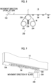
- the pressing roller 256 presses the wiping web W against the nozzle surface 14A.
- the pressurization device 258 applies a pressure toward the nozzle surface 14A to the pressing roller 256 to press the wiping web W against the nozzle surface 14A via the pressing roller 256.
- An upward arrow line shown in Fig. 8 indicates a direction of the pressure applied to the wiping web W.
- Fig. 10 is an overall configuration diagram of the printing system according to the embodiment.
- An inkjet method is applied to a printing system 300 to execute single-pass printing.
- the printing system 300 shown in Fig. 10 comprises the ink supply device 10 described with reference to Figs. 1 to 9 .
- a roller coating method is applied in which the paper S is interposed between the coating roller 342 to which the pretreatment liquid is supplied and the facing roller 344, and the pretreatment liquid is applied to the printing surface of the paper S.
- a liquid reservoir or the like in which the pretreatment liquid supplied to the coating roller 342 is stored is not shown.
- a coating method of the pretreatment liquid applied to the pretreatment liquid coating device 340 is not limited to the roller coating method.
- a coating method other than the roller coating method such as a blade coating method using a blade, can be applied.
- the printing device 350 prints a color image on the printing surface of the paper S.
- the printing device 350 comprises an inkjet bar 14K, an inkjet bar 14C, an inkjet bar 14M, an ink jet bar 14Y, and an inkjet bar 14W.
- Each of the ink jet bar 14K, the ink jet bar 14C, the ink jet bar 14M, the ink jet bar 14Y, and the ink jet bar 14W shown in Fig. 10 corresponds to the ink jet bar 14 shown in Fig. 1 .
- the printing device 350 comprises an ink supply device 10K, an ink supply device 10C, an ink supply device 10M, an ink supply device 10Y, and an ink supply device 10W.
- Each of the ink supply device 10K and the like supplies ink of the corresponding color to each of the ink jet bar 14K and the like.
- Each of the ink supply device 10K, the ink supply device 10C, the ink supply device 10M, the ink supply device 10Y, and the ink supply device 10W shown in Fig. 10 corresponds to the ink supply device 10 shown in Fig. 1 .
- the inkjet bar 14K, the inkjet bar 14C, the inkjet bar 14M, the inkjet bar 14Y, and the inkjet bar 14W may be collectively referred to as the inkjet bar 14.
- the white ink described in the embodiment is an example of the first ink
- the black ink, the cyan ink, the magenta ink, and the yellow ink described in the embodiment are examples of the second ink.
- the ink supply device 10W described in the embodiment is an example of a first liquid supply device and is an example of a first ink supply device.
- the ink supply device 10K, the ink supply device 10C, the ink supply device 10M, and the ink supply device 10Y described in the embodiment are examples of a second liquid supply device, and are examples of a second ink supply device.
- the pump 130 provided in the ink supply device 10W described in the embodiment is an example of a component of a first pressurization device.
- the pump 130 provided in the ink supply device 10K, the ink supply device 10C, the ink supply device 10M, and the ink supply device 10Y described in the embodiment is an example of a component of a second pressurization device.
- the aqueous ink includes an ink in which pigment particles are dispersed in a solvent such as water.
- a solvent such as water.
- titanium oxide is applied as a material of pigment particles capable of being sedimented in a solvent.
- a value more than 100 nanometers can be applied as an average particle diameter of the titanium oxide particles contained in the white ink.
- the average particle diameter a particle diameter having an integrated value of 50% in particle size distribution derived by using a laser diffraction scattering method can be applied.
- CCD is an abbreviation for charge coupled device.
- CMOS is an abbreviation for complementary metal oxide semiconductor.
- the paper S on which the color image is printed using the printing device 350 is conveyed to the drying device 370.
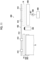
- FIG. 11 is a plan view showing a configuration example of a maintenance device.
- a maintenance device 400 comprises a head moving device 402 that moves the inkjet bar 14.
- the head moving device 402 moves the ink jet bar 14 between a printing position and a maintenance position.
- Fig. 11 shows a configuration comprising a carriage 410 connected to the ink jet bar 14 and a guide 412 that supports the carriage 410, as a configuration example of the head moving device 402.
- a linear movement mechanism connected to the carriage 410, a motor connected to the linear movement mechanism, and the like are not shown.
- the printing position is a position of the ink jet bar 14 at which printing is executed on the paper S by jetting an ink from the ink jet bar 14.
- Fig. 11 shows the ink jet bar 14 located at the printing position by using a solid line.
- the maintenance position is a position of the ink jet bar 14 at which maintenance of the inkjet bar 14 is executed.
- the maintenance of the ink jet bar 14 includes wiping the nozzle surface 14A to which a wiping device 404 is applied, pre-j etting to discharge the ink from the nozzle opening to a cap 406 by operating a jetting element for each nozzle, and moisturizing in which a moisturizing liquid inside the cap 406 is applied.
- the cap 406 is connected to a discharge tank 409 via a discharge flow passage 407 and a discharge pump 408.
- the ink discharged to the cap 406 is fed to the discharge tank 409 by operating the discharge pump 408.
- Fig. 11 shows the ink jet bar 14 at a maintenance execution position to which the cap 406 is applied among the maintenance positions by using a one-dot chain line.
- the maintenance position includes a position at which wiping of the nozzle surface 14Ais executed by using the wiping device 404.
- the wiping device 260 shown in Fig. 9 may be applied.
- Fig. 12 is a perspective view showing a configuration example of the ink jet bar.
- the supply-side back pressure tank 30, the supply-side head manifold 32, and the like shown in Fig. 1 are not shown.
- the inkjet bar 14 has a structure in which a plurality of head modules 15 are connected to each other along a longitudinal direction.
- the plurality of head modules 15 are integrally supported by a support frame 420.
- the flexible substrate 422 is formed with an electrical wiring line for transmitting a driving voltage supplied to a jetting element provided in the head module 15.
- the jetting element comprises a nozzle opening, a flow passage communicating with the nozzle opening, and an energy generation element.
- the energy generation element apply a jetting pressure to the ink jetted from the nozzle opening.
- a piezoelectric element can be applied as the energy generation element. In Fig. 12 , the nozzle opening, the flow passage, and the energy generation element are not shown.
- the pressure chamber 464 corresponding to each of the nozzle openings 480 has a planar shape of a substantially square shape, and an outlet port to the nozzle opening 480 is disposed at one of both corner portions on a diagonal line, and the individual supply path 462, which is an inlet of the ink, is disposed at the other.
- the shape of the pressure chamber is not limited to square.
- the planar shape of the pressure chamber may be various forms such as a rectangle such as a rhombus and a quadrangle, a pentagon, a hexagon or other polygons, a circle, and an ellipse.
- the storage device 522 stores various data, various programs, and various parameters applied to the printing system 300.
- a computer configured as a control device of the printing system 300 uses various data and executes various programs with reference to various parameters to realize various functions of the printing system 300.
Landscapes
- Chemical & Material Sciences (AREA)
- Life Sciences & Earth Sciences (AREA)
- Engineering & Computer Science (AREA)
- Materials Engineering (AREA)
- Wood Science & Technology (AREA)
- Organic Chemistry (AREA)
- Ink Jet (AREA)
Abstract
Description
- The present invention relates to a liquid supply device, a liquid jetting system, a printing system, and a liquid circulation method.
- A white ink using pigment particles such as titanium oxide has a relatively large size of the pigment particles and a relatively high density of the pigment particles compared to color inks other than white. Then, in the white ink, the pigment particles precipitate in the ink, which may cause a jetting failure of an inkjet head in which the white ink is used.
-
JP6303327B JP6303327B -
JP6582453B JP6582453B - However, although
JP6303327B JP6582453B JP6303327B JP6582453B - The present invention has been made in view of such circumstances, and an object of the present invention is to provide a liquid supply device, a liquid jetting system, a printing system, and a liquid circulation method capable of suppressing sedimentation of particles dispersed in a solvent in a case of circulating a liquid in which the particles are likely to be sedimented.
- According to the present disclosure, there is provide a liquid supply device that supplies a liquid to a liquid jetting head, the liquid supply device comprising: a circulation flow passage that communicates with a circulation port of the liquid jetting head and communicates with a supply port of the liquid jetting head; a pressurization device that pressurizes a liquid inside the circulation flow passage; at least one processor; and at least one memory that stores a command to be executed by the at least one processor, in which the at least one processor is configured to control the pressurization device to pressurize the liquid in a case in which the liquid is circulated by using the circulation flow passage, and in a case in which a first liquid which has particles dispersed in a solvent and has a particle sedimentation characteristic different from that of a second liquid and in which the particles are likely to be sedimented is circulated as the liquid, apply, to the first liquid, a pressure that is equal to or more than 2.0 times and equal to or less than 3.5 times a pressure to be applied to the second liquid in a case in which the second liquid is circulated.
- With the liquid supply device according to the present disclosure, a pressure to be applied to the first liquid in a case in which the first liquid in which the particles are more likely to be sedimented than the second liquid is circulated is set to be equal to or more than 2 times and equal to or less than 3.5 times the pressure in a case in which the second liquid is circulated. As a result, it is possible to suppress the sedimentation of the particles in a case in which the first liquid is circulated.
- A case in which the second liquid is circulated includes a case in which the second liquid is circulated by using the circulation flow passage and the pressurization device in a case in which the second liquid is used instead of the first liquid as the liquid to be supplied to the liquid jetting head.
- The first liquid and the second liquid may have a common major component of a solvent. The particles contained in the first liquid and the particles contained in the second liquid may be made of different materials from each other.
- As the difference in sedimentation characteristics, a sedimentation velocity of the particles dispersed in the solvent can be applied.
- In the liquid supply device according to another aspect, a filter for filtering the liquid may be attached to the circulation flow passage, and in a case in which the first liquid is used, the filter may be applied with a structure having a larger mesh size than in a case in which the second liquid is used.
- According to such an aspect, occurrence of soft aggregation of the first liquid in the filter provided in the circulation flow passage is suppressed. As a result, it is possible to suppress clogging of the filter due to the occurrence of the soft aggregation of the first liquid.
- In the liquid supply device according to another aspect, a filter for filtering the liquid may be attached to the circulation flow passage, and in a case in which the first liquid is used, the filter may be applied with a structure having a larger cross-sectional area than in a case in which the second liquid is used.
- According to such an aspect, clogging of the filter in a case in which the first liquid is circulated can be suppressed.
- In the liquid supply device according to another aspect, the first liquid may contain titanium oxide particles as pigment particles.
- According to such an aspect, sedimentation of the titanium oxide particles in a case in which the first liquid containing titanium oxide as the pigment particles is circulated can be suppressed.
- In the liquid supply device according to another aspect, in a case in which the first liquid is used, the pressurization device may have relatively higher pressurization performance than in a case in which the second liquid is used.
- According to such an aspect, in a case in which the first liquid is circulated, shortening of the life of the pressurization device can be suppressed compared to a case in which the second liquid is circulated.
- In the liquid supply device according to another aspect, a diameter of the particles contained in the first liquid may be larger than a diameter of particles contained in the second liquid.
- In the liquid supply device according to another aspect, a density of the particles in the first liquid may be larger than a density of particles contained in the second liquid.
- In the liquid supply device according to another aspect, a value obtained by subtracting a density of the solvent from a density of the particles in the first liquid may be larger than a value obtained by subtracting a density of a solvent from a density of particles in the second liquid.
- According to the present disclosure, there is provided a liquid jetting system using a first liquid and a second liquid, the liquid jetting system comprising: a first liquid jetting head that jets a first liquid which has particles dispersed in a solvent and has a particle sedimentation characteristic different from that of the second liquid and in which the particles are likely to be sedimented; a first liquid supply device that supplies the first liquid to the first liquid jetting head and includes a first circulation flow passage which communicates with a circulation port of the first liquid jetting head and communicates with a supply port of the first liquid jetting head and a first pressurization device that pressurizes the first liquid inside the first circulation flow passage; a second liquid jetting head that jets the second liquid; and a second liquid supply device that supplies the second liquid to the second liquid jetting head and includes a second circulation flow passage which communicates with a circulation port of the second liquid jetting head and communicates with a supply port of the second liquid jetting head and a second pressurization device that pressurizes the second liquid inside the second circulation flow passage; at least one processor; and at least one memory that stores a command to be executed by the at least one processor, in which the at least one processor is configured to control the first pressurization device to pressurize the first liquid in a case in which the first liquid is circulated by using the first circulation flow passage, and in a case in which the first liquid is circulated, apply, to the first liquid, a pressure that is equal to or more than 2.0 times and equal to or less than 3.5 times a pressure to be applied to the second liquid in a case in which the second liquid is circulated by using the second circulation flow passage.
- With the liquid jetting system according to the present disclosure, a pressure to be applied to the first liquid in a case in which the first liquid in which pigment particles are more likely to be sedimented than the second liquid is circulated is set to be equal to or more than 2 times and equal to or less than 3.5 times the pressure in a case in which the second liquid is circulated. As a result, it is possible to suppress the sedimentation of the pigment particles in a case in which the first liquid is circulated.
- Configuration requirements of the liquid supply system according to another aspect can be applied to configuration requirements of the liquid jetting system according to another aspect.
- In the liquid jetting system according to another aspect, the at least one processor may be configured to, in a case in which the first liquid is circulated during execution of a liquid jetting job in which printing is executed by using the first liquid jetting head, apply, to the first liquid, a pressure that is equal to or more than 2.0 times and equal to or less than 3.5 times the pressure in a case in which the second liquid is circulated.
- According to such an aspect, in a case in which the first liquid is circulated during the execution of the liquid jetting job, the sedimentation of the pigment particles in the first liquid can be suppressed.
- During the execution of the liquid jetting job, at least one of the first liquid jetting head or the second liquid jetting head need only execute liquid jetting.
- In the liquid jetting system according to another aspect, the at least one processor may be configured to, in a case in which the first liquid is circulated during a standby time in which the liquid jetting job is not executed, reduce a pressure to be applied to the first liquid compared to a case in which the first liquid is circulated during the execution of the liquid jetting job.
- According to such an aspect, in a case in which the first liquid is circulated during a standby time of the liquid jetting head, a load on the first pressurization device can be reduced compared with a case in which the first liquid is circulated during the execution of the liquid jetting job. As a result, it is possible to suppress shortening of the life of the first pressurization device.
- The liquid jetting system according to another aspect may further comprise: a wiping device that wipes a nozzle surface of the first liquid jetting head, and the at least one processor may be configured to, in a case in which the first liquid is circulated in a case in which the nozzle surface of the first liquid jetting head is wiped by using the wiping device, reduce a pressure to be applied to the first liquid compared to a case in which the first liquid is circulated during the execution of the liquid jetting job.
- According to such an aspect, in a case in which the first liquid is circulated during the wiping of the nozzle surface of the first liquid jetting head, a load on the first pressurization device can be reduced compared with a case in which the first liquid is circulated during the execution of the liquid jetting job. As a result, it is possible to suppress shortening of the life of the first pressurization device.
- According to the present disclosure, there is provided a printing system that executes printing using a first ink and a second ink, the printing system comprising: a first ink jet head that jets a first ink which has particles dispersed in a solvent and has a particle sedimentation characteristic different from that of the second ink and in which the particles are likely to be sedimented; a first ink supply device that supplies the first ink to the first ink jet head and includes a first circulation flow passage which communicates with a circulation port of the first ink jet head and communicates with a supply port of the first ink jet head and a first pressurization device that pressurizes the first ink inside the first circulation flow passage; a second inkjet head that jets the second ink; a second ink supply device that supplies the second ink to the second ink jet head and includes a second circulation flow passage which communicates with a circulation port of the second inkjet head and communicates with a supply port of the second ink jet head and a second pressurization device that pressurizes the second ink inside the second circulation flow passage; at least one processor; and at least one memory that stores a command to be executed by the at least one processor, in which the at least one processor is configured to control the first pressurization device to pressurize the first ink in a case in which the first ink is circulated by using the first circulation flow passage, and in a case in which the first ink is circulated, apply, to the first ink, a pressure that is equal to or more than 2.0 times and equal to or less than 3.5 times a pressure to be applied to the second ink in a case in which the second ink is circulated by using the second circulation flow passage.
- With the printing system according to the present disclosure, it is possible to obtain the same functions and effects as those of the liquid supply system according to the present disclosure. Configuration requirements of the liquid supply system according to another aspect and configuration requirements of the liquid jetting system according to another aspect can be applied to configuration requirements of the printing system according to another aspect.
- According to the present disclosure, there is provided a liquid circulation method of, via a liquid supply device that supplies a liquid to a liquid jetting head, circulating a liquid from a circulation port of the liquid jetting head to a supply port of the liquid jetting head by using a circulation flow passage that communicates with the circulation port and communicates with the supply port, the liquid circulation method comprising: causing a computer to in a case in which the liquid is circulated by using the circulation flow passage, control a pressurization device to pressurize a liquid inside the circulation flow passage, and in a case in which a first liquid which contains particles and has a particle sedimentation characteristic different from that of a second liquid and in which the particles are likely to be sedimented is circulated as the liquid, apply, to the first liquid, a pressure that is equal to or more than 2.0 times and equal to or less than 3.5 times a pressure in a case in which the second liquid is circulated.
- With the liquid circulation method according to the present disclosure, it is possible to obtain the same functions and effects as those of the liquid supply system according to the present disclosure. Configuration requirements of the liquid supply system according to another aspect and configuration requirements of the liquid jetting system according to another aspect can be applied to configuration requirements of the liquid circulation method according to another aspect.
- According to the present invention, a pressure to be applied to the first liquid in a case in which the first liquid in which the particles are more likely to be sedimented than the second liquid is circulated is set to be equal to or more than 2 times and equal to or less than 3.5 times the pressure in a case in which the second liquid is circulated. As a result, it is possible to suppress the sedimentation of the particles in a case in which the first liquid is circulated.
-
-
Fig. 1 is an overall configuration diagram of an ink supply device according to an embodiment. -
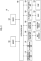
Fig. 2 is a functional block diagram showing an electric configuration of the ink supply device shown inFig. 1 . -
Fig. 3 is a block diagram showing a configuration example of hardware of the ink supply device shown inFig. 1 . -
Fig. 4 is a schematic diagram showing a main ink flow in ink circulation. -
Fig. 5 is a table showing results of an evaluation experiment. -
Fig. 6 is a graph showing a relationship between a pressure difference and the number of defective nozzles. -
Fig. 7 is a flowchart showing a flow of a procedure of an ink circulation method according to the embodiment. -
Fig. 8 is a schematic diagram showing wiping cleaning of a nozzle. -
Fig. 9 is a schematic diagram showing another example of wiping cleaning of the nozzle. -
Fig. 10 is an overall configuration diagram of a printing system according to the embodiment. -
Fig. 11 is a plan view showing a configuration example of a maintenance device. -
Fig. 12 is a perspective view showing a configuration example of an inkjet bar. -
Fig. 13 is a perspective view of a head module and is a diagram including a partial cross-sectional view. -
Fig. 14 is a cross-sectional view showing an internal structure of the head module. -
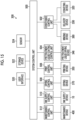
Fig. 15 is a functional block diagram showing an electric configuration of the printing system shown inFig. 10 . - Hereinafter, preferred embodiments of the present invention will be described with reference to the accompanying drawings. In the present specification, the same components are denoted by the same reference numerals, and duplicate description thereof will be omitted as appropriate.
-
Fig. 1 is an overall configuration diagram of an ink supply device according to an embodiment. Anink supply device 10 is a device that supplies ink to anink jet bar 14, and comprises abuffer tank 12, asupply flow passage 16, and arecovery flow passage 18. - In the
buffer tank 12, ink to be supplied to theink jet bar 14 is temporarily stored. Theink supply device 10 stably supplies ink from thebuffer tank 12 to theink jet bar 14 in accordance with the ink consumption of theink jet bar 14. - The
buffer tank 12 comprises asupply port 12A, arecovery port 12B, abypass port 12C, and anoverflow port 12D. Thesupply port 12A is connected to thesupply flow passage 16 via a joint. Therecovery port 12B is connected to therecovery flow passage 18 via a joint. Thebypass port 12C is connected to areplenishment flow passage 78 via a joint. Theoverflow port 12D is connected to anoverflow passage 80 via a joint. InFig. 1 , a joint that connects thebuffer tank 12 and each flow passage is not shown. - The
buffer tank 12 and theinkjet bar 14 communicate with each other through thesupply flow passage 16 via a joint F1. Theinkjet bar 14 and thebuffer tank 12 communicate with each other through therecovery flow passage 18 via a joint F2. The ink stored in thebuffer tank 12 is supplied to theink jet bar 14 via thesupply flow passage 16. In addition, the ink that is not used in theink jet bar 14 is recovered to thebuffer tank 12 via therecovery flow passage 18. - The
supply flow passage 16 and therecovery flow passage 18 are configured to include a flow passage constituent member such as a tube. A flow passage control device, such as a pump or a valve, is connected to thesupply flow passage 16 and therecovery flow passage 18 by using a joint F. - A
deaeration module 22, asupply pump 24, a supply-side filter 26, and aheat exchanger 28 are connected to thesupply flow passage 16 as a flow passage control device. - The
deaeration module 22 performs a deaeration treatment on the ink passing through thesupply flow passage 16. Thesupply pump 24 applies pressure to the ink inside thesupply flow passage 16 to cause the ink inside thesupply flow passage 16 to generate a flow. As thesupply pump 24, a tube pump can be applied. The supply-side filter 26 removes air bubbles, foreign matter, and the like contained in the ink. Theheat exchanger 28 adjusts a temperature of the ink. - A
recovery pump 50 and a recoveryflow passage valve 52 are connected to therecovery flow passage 18 as a flow passage control device. Therecovery pump 50 applies pressure to the ink inside therecovery flow passage 18 to cause the ink inside therecovery flow passage 18 to generate a flow. As therecovery pump 50, a tube pump can be applied. The recoveryflow passage valve 52 operates in response to a control signal to switch between opening and closing of therecovery flow passage 18 between therecovery pump 50 and thebuffer tank 12. - The
ink supply device 10 comprises an inkmain tank 76, areplenishment flow passage 78, anoverflow passage 80, and areplenishment pump 82. Thereplenishment flow passage 78 and theoverflow passage 80 are provided with a joint F. - The ink
main tank 76 stores the ink to be supplied to thebuffer tank 12. The inkmain tank 76 and therecovery port 12B of thebuffer tank 12 communicate with each other through thereplenishment flow passage 78 via a joint F. The inkmain tank 76 and theoverflow port 12D of thebuffer tank 12 communicate with each other through theoverflow passage 80 via a joint F. - The
replenishment pump 82 applies pressure to the ink inside thereplenishment flow passage 78 to cause the ink inside thereplenishment flow passage 78 to generate a flow. As thereplenishment pump 82, a tube pump can be applied. In accordance with the driving of thereplenishment pump 82, the ink is replenished from the inkmain tank 76 to thebuffer tank 12. -
Amain tank filter 76A is provided at an end of thereplenishment flow passage 78 on the side of the inkmain tank 76. Themain tank filter 76A removes foreign matter and the like from the ink replenished from the inkmain tank 76 to thebuffer tank 12. - In a case in which the
buffer tank 12 is replenished with the ink in excess of a predetermined amount of thebuffer tank 12, the ink is returned from thebuffer tank 12 to the inkmain tank 76 via theoverflow port 12D and theoverflow passage 80. - The
ink supply device 10 comprises afirst safety valve 84, asecond safety valve 86, athird safety valve 88, a recovery-side filter 90, and a recovery-side filter valve 92. - In the
ink supply device 10, in a case in which internal pressure of thesupply flow passage 16 rises above a predetermined value, thefirst safety valve 84 and thesecond safety valve 86 operate to reduce the internal pressure of thesupply flow passage 16. In addition, in theink supply device 10, in a case in which internal pressure of therecovery flow passage 18 rises above a predetermined value, thethird safety valve 88 operates to reduce the internal pressure of therecovery flow passage 18. - The recovery-
side filter valve 92 operates in response to a control signal to switch between opening and closing between therecovery pump 50 and thedeaeration module 22. Theink supply device 10 maintains the recovery-side filter valve 92 in an opened state, and allows the ink that has passed through thedeaeration module 22 to pass through the recovery-side filter 90. - The
ink supply device 10 comprises abypass flow passage 54. Ajoint F3 of theink jet bar 14 and thebypass port 12C of thebuffer tank 12 communicate with each other through thebypass flow passage 54. Thebypass flow passage 54 is a flow passage through which the ink is fed from theink jet bar 14 to thebuffer tank 12 without passing through therecovery flow passage 18. Thebypass flow passage 54 is provided with a joint F. - The
ink supply device 10 shown inFig. 1 may not be provided with theheat exchanger 28 or the like. For example, in a case in which it is unnecessary to adjust an ink temperature, such as a case in which an environmental temperature such as a room temperature is applied as the ink temperature, theheat exchanger 28 need not be provided. - In addition, in a case in which the
buffer tank 12 has a function of the inkmain tank 76, a flow passage control device such as the inkmain tank 76, a flow passage connected to the inkmain tank 76, such as theoverflow passage 80, and a pump and a valve connected to the inkmain tank 76 may not be provided. - The joint F1 described in the embodiment is an example of a supply port of a liquid jetting head. The joint F2 described in the embodiment is an example of a circulation port of the liquid jetting head. The
supply flow passage 16 described in the embodiment is an example of a component of a circulation flow passage, and therecovery flow passage 18 described in the embodiment is an example of a component of the circulation flow passage. - The
ink jet bar 14 shown inFig. 1 is a line-type ink jet head that comprises a plurality ofhead modules 15 and has a structure in which the plurality ofhead modules 15 are joined together.Fig. 1 illustrates theink jet bar 14 comprising n pieces of thehead modules 15.Fig. 1 shows three head modules denoted by reference numerals 15-1, 15-2, and 15-n among the n pieces of the head modules. The same applies toFig. 4 . - The
inkjet bar 14 is not limited to the aspect in which the plurality ofhead modules 15 are provided, and may adopt an aspect in which onehead module 15 is provided. That is, n representing the number of thehead modules 15 may be an integer of one or more. - The
ink jet bar 14 comprises the supply-side backpressure tank 30. The supply-side backpressure tank 30 is a pressure buffering device that suppresses fluctuations in the internal pressure of thesupply flow passage 16. The supply-side backpressure tank 30 communicates with thesupply flow passage 16 via anink inlet 30A and the joint F1. - The supply-side back
pressure tank 30 comprises anink outlet 30B, aliquid chamber 30C, anair chamber 30D, anelastic film 30E, an airbubble discharge port 30F, and an air flowpassage communication port 30G. The ink that has flowed in from theink inlet 30A flows out from theink outlet 30B via theliquid chamber 30C. - The
elastic film 30E is disposed between theliquid chamber 30C and theair chamber 30D, and separates theliquid chamber 30C and theair chamber 30D. Theelastic film 30E is deformed according to the pressure fluctuation of the ink passing through theliquid chamber 30C to reduce the pressure fluctuation of the ink passing through theliquid chamber 30C. - The
air chamber 30D communicates with anair flow passage 58 via the air flowpassage communication port 30G. Theair chamber 30D and anair tank 60 communicate with each other through theair flow passage 58 via anair connect valve 59. Theair tank 60 can communicate with anatmospheric communication path 61. Theatmospheric communication path 61 is provided with anair valve 62. - The air
bubble discharge port 30F of theliquid chamber 30C communicates with thebypass flow passage 54 via thedrain flow passage 47 and the joint F3. Thedrain flow passage 47 is provided with adrain valve 56. Thedrain valve 56 operates in response to a control signal to switch between opening and closing of thedrain flow passage 47. - The
inkjet bar 14 comprises the supply-side head manifold 32. The supply-side head manifold 32 communicates with theink outlet 30B via the flow passage. The ink discharged from the supply-side backpressure tank 30 flows into the supply-side head manifold 32. - The supply-
side head manifold 32 comprises a supply-side pressure sensor 34. The supply-side pressure sensor 34 detects internal pressure of the supply-side head manifold 32. The supply-side head manifold 32 is subjected to pressure control according to a detection result of the supply-side pressure sensor 34. - As the supply-
side pressure sensor 34, a sensor of a semiconductor piezo resistance type, a capacitance type, a silicon resonant type, or the like can be applied. The same applies to a recovery-side pressure sensor 46. - The
inkjet bar 14 comprises inksupply flow passages 35 as many as the number of thehead modules 15. The supply-side head manifold 32 communicates with thehead module 15 via the inksupply flow passage 35, and supplies the ink to thehead module 15 via anink supply port 15A via the inksupply flow passage 35. - Each of the ink
supply flow passages 35 is provided with asupply valve 36 and asupply damper 38. InFig. 1 , only one of n pieces of the inksupply flow passages 35 is denoted by a reference numeral. The same applies to n pieces of thesupply valves 36 and n pieces of thesupply dampers 38. - The
inkjet bar 14 comprises inkrecovery flow passages 39 as many as the number of thehead modules 15. The inkrecovery flow passage 39 is connected to each of thehead modules 15. - The
ink jet bar 14 comprises a recovery-side head manifold 44. Each of thehead modules 15 communicates with the recovery-side head manifold 44 via the inkrecovery flow passage 39, and discharges the ink from anink discharge port 15B to the recovery-side head manifold 44 via the inkrecovery flow passage 39. - The recovery-
side head manifold 44 comprises the recovery-side pressure sensor 46. The recovery-side pressure sensor 46 detects internal pressure of the recovery-side head manifold 44. The recovery-side head manifold 44 is subjected to pressure control according to a detection result of the recovery-side pressure sensor 46. - Each of the ink
recovery flow passages 39 is provided with therecovery damper 40 and therecovery valve 42. InFig. 1 , only one of n pieces of therecovery dampers 40 is denoted by a reference numeral. The same applies to n pieces of therecovery valves 42. - The
inkjet bar 14 comprises a recovery-side backpressure tank 48. The recovery-side backpressure tank 48 is a pressure buffering device that suppresses fluctuations in internal pressure of the recovery-side head manifold 44, and a flow passage between the recovery-side head manifold 44 and the recovery-side head manifold 44 and the joint F3. - An
ink inlet 48A of the recovery-side backpressure tank 48 communicates with the recovery-side head manifold 44 via a flow passage. The recovery-side backpressure tank 48 comprises anink outlet 48B. The recovery-side backpressure tank 48 communicates with therecovery flow passage 18 via theink outlet 48B and the joint F2. - The recovery-side back
pressure tank 48 comprises aliquid chamber 48C, anair chamber 48D, anelastic film 48E, and an air flowpassage communication port 48G. Each of theliquid chamber 48C, theair chamber 48D, and theelastic film 48E has the same structure and function as theliquid chamber 30C, theair chamber 30D, and theelastic film 30E provided in the supply-side backpressure tank 30. - The
air chamber 48D communicates with theair flow passage 71 via the air flowpassage communication port 48G. Theair flow passage 71 communicates theair chamber 48D and theair tank 73 via the air connectvalve 72, and theair tank 73 communicates with theatmospheric communication path 74. Theatmospheric communication path 74 is provided with anair valve 75. - An air
bubble discharge port 48F of theliquid chamber 48C is connected to thebypass flow passage 54 via thedrain flow passage 49 and the joint F3. Thedrain flow passage 49 is provided with adrain valve 70. Thedrain valve 70 operates in response to a control signal to switch between opening and closing of thedrain flow passage 49. - The
ink jet bar 14 comprises a firstbypass flow passage 64 and a secondbypass flow passage 66. The supply-side head manifold 32 and the recovery-side head manifold 44 communicate with each other through the firstbypass flow passage 64 and the secondbypass flow passage 66. - The first
bypass flow passage 64 is provided with a first bypassflow passage valve 68. The first bypassflow passage valve 68 operates in response to a control signal to switch between opening and closing of the firstbypass flow passage 64. The secondbypass flow passage 66 is provided with a second bypassflow passage valve 69. The second bypassflow passage valve 69 switches between opening and closing of the secondbypass flow passage 66 in response to a control signal. - Among the components of the
inkjet bar 14 shown inFig. 1 , components other than thehead module 15, such as the supply-side backpressure tank 30 and the supply-side head manifold 32, may be components of theink supply device 10. In such an aspect, an arrangement of the joint F1 or the like that connects theink supply device 10 and theinkjet bar 14 is changed as appropriate. -
Fig. 1 illustrates theink supply device 10 that supplies one color of ink to oneink jet bar 14. A printing system comprising a plurality of ink jet bars 14 respectively corresponding to a plurality of colors of ink comprises theink supply device 10 for the number of colors. - Note that the configuration of the
ink supply device 10 shown inFig. 1 is an example, and components can be added, changed, or deleted as appropriate. - In the present embodiment, the aspect in which the ink is supplied from the
ink supply device 10 to theink jet bar 14 has been illustrated, but theink supply device 10 may adopt an aspect in which a liquid other than the ink, such as a functional liquid, is supplied to a liquid supply target device. - The
ink supply device 10 described in the embodiment is an example of a liquid supply device. Theinkjet bar 14 described in the embodiment is an example of the liquid jetting head. -
Fig. 2 is a functional block diagram showing an electric configuration of the ink supply device shown inFig. 1 . Theink supply device 10 comprises asystem control unit 100, apump control unit 102, avalve control unit 104, adeaeration control unit 106, and a heatexchange control unit 108. - The
system control unit 100 transmits a command signal to thepump control unit 102, thevalve control unit 104, thedeaeration control unit 106, and the heatexchange control unit 108 to integrally control an operation of theink supply device 10. - The
pump control unit 102 controls an operation of apump 130 in response to a command signal transmitted from thesystem control unit 100. Thepump 130 shown inFig. 2 includes thesupply pump 24, therecovery pump 50, and thereplenishment pump 82 shown inFig. 1 . - That is, the
pump control unit 102 controls the operation of various pumps provided in the flow passage through which the ink returning from thebuffer tank 12 to thebuffer tank 12 via theinkjet bar 14 passes, and defines a flow velocity of the ink and a flow direction of the ink. - The
valve control unit 104 controls an operation of avalve 132 in response to a command signal transmitted from thesystem control unit 100. Thevalve 132 shown inFig. 2 includes the recoveryflow passage valve 52, the recovery-side filter valve 92, and the like shown inFig. 1 . Thevalve 132 shown inFig. 2 may include various valves such as thedrain valve 56 and thedrain valve 70 provided in theinkjet bar 14 shown inFig. 1 . - That is, the
valve control unit 104 switches between opening and closing of various valves provided in a flow passage through which the ink returning from thebuffer tank 12 to thebuffer tank 12 via theinkjet bar 14 passes, and defines the flow passage through which the ink passes. - The
deaeration control unit 106 controls an operation of thedeaeration module 22 in response to a command signal transmitted from thesystem control unit 100, and executes a deaeration treatment on the ink supplied from thebuffer tank 12 to theink jet bar 14. - The heat
exchange control unit 108 controls an operation of theheat exchanger 28 in response to a command signal transmitted from thesystem control unit 100, and executes temperature adjustment of the ink supplied from thebuffer tank 12 to theinkjet bar 14. - The
ink supply device 10 comprises anink determination unit 110 and a printingstate determination unit 112. Thesystem control unit 100 determines a type of an ink to be used in theink supply device 10 based on an ink determination result transmitted from theink determination unit 110. Thesystem control unit 100 executes control of theink supply device 10 according to the type of the ink. - In addition, the
system control unit 100 determines whether the printing system is in a printing state or in a non-printing state based on a signal transmitted from the printingstate determination unit 112. Thesystem control unit 100 executes control of theink supply device 10 according to the state of the printing system. - The
ink supply device 10 comprises amemory 120. Thememory 120 stores various data, various parameters, various programs, and the like used for controlling theink supply device 10. Thesystem control unit 100 executes control of each part of theink supply device 10 by applying various parameters and the like stored in thememory 120. - The
ink supply device 10 comprises asensor 122. Thesensor 122 shown inFig. 2 includes various sensors provided in theink supply device 10, such as a temperature sensor and a pressure sensor. Thesensor 122 may include various sensors such as the supply-side pressure sensor 34 provided in theinkjet bar 14 shown inFig. 1 . -
Fig. 3 is a block diagram showing a configuration example of hardware of the ink supply device shown inFig. 1 . Acontrol device 200 provided in theink supply device 10 comprises aprocessor 202, a non-temporary tangible computer-readable medium 204, acommunication interface 206, and an input/output interface 208. - A computer is applied as the
control device 200. A form of the computer may be a server, a personal computer, a workstation, a tablet terminal, and the like. - The
processor 202 comprises a central processing unit (CPU) which is a general-purpose processing device. Theprocessor 202 may comprise a graphics processing unit (GPU) which is a processing device specialized in image processing. - The
processor 202 is connected to the computer-readable medium 204, thecommunication interface 206, and the input/output interface 208 via abus 210. Aninput device 214 and adisplay device 216 are connected to thebus 210 via the input/output interface 208. - The computer-readable medium 204 comprises a memory which is a main memory and a storage which is an auxiliary memory. A semiconductor memory, a hard disk apparatus, a solid state drive apparatus, and the like can be applied as the computer-readable medium 204. Any combination of a plurality of devices can be applied as the computer-readable medium 204.
- The hard disk apparatus can be referred to as an HDD which is an abbreviation for Hard Disk Drive in English. The solid state drive apparatus can be referred to as an SSD which is an abbreviation for Solid State Drive in English.
- The
control device 200 is connected to a network via thecommunication interface 206, and is communicably connected to an external device. A local area network (LAN) and the like can be used as the network. The network is not shown. - The computer-readable medium 204 stores a
pump control program 220, avalve control program 222, adeaeration control program 224, a heatexchange control program 226, anink determination program 228, and a printingstate determination program 230. The computer-readable medium 204 can function as thememory 120 shown inFig. 2 . - The
pump control program 220 corresponds to operation control applied to thepump 130 shown inFig. 2 . Thevalve control program 222 corresponds to operation control applied to thevalve 132. Thedeaeration control program 224 corresponds to deaeration control applied to thedeaeration module 22. The heatexchange control program 226 corresponds to ink temperature control applied to theheat exchanger 28. Theink determination program 228 corresponds to processing of determining the type of the ink. The printingstate determination program 230 corresponds to processing of determining the printing state. - Various programs stored in the computer-readable medium 204 include one or more commands. The computer-readable medium 204 stores various data, various parameters, and the like.
- In the
ink supply device 10, theprocessor 202 executes various programs stored in the computer-readable medium 204 to realize various functions in theink supply device 10. The term "program" is synonymous with the term "software". - The
control device 200 executes data communication with an external device via thecommunication interface 206. Various standards such as universal serial bus (USB) can be applied to thecommunication interface 206. As a communication form of thecommunication interface 206, either wired communication or wireless communication may be applied. - The
input device 214 and thedisplay device 216 are connected to thecontrol device 200 via the input/output interface 208. An input device such as a keyboard or a mouse is applied as theinput device 214. Thedisplay device 216 displays various information applied to thecontrol device 200. - A liquid crystal display, an organic EL display, a projector, and the like can be applied as the
display device 216. Any combination of a plurality of devices can be applied as thedisplay device 216. The term "EL" of an organic EL display is an abbreviation for ElectroLuminescence. - Here, examples of a hardware structure of the
processor 202 include a CPU, a GPU, a programmable logic device (PLD), and an application specific integrated circuit (ASIC). The CPU is a general-purpose processor that executes a program and acts as various functional units. The GPU is a processor specialized in image processing. - The PLD is a processor capable of changing a configuration of an electric circuit after manufacturing a device. An example of the PLD is a field programmable gate array (FPGA). The ASIC is a processor comprising a dedicated electric circuit specifically designed to execute a specific process.
- One processing unit may be configured by one of these various processors or may be composed of two or more processors of the same type or different types. Examples of a combination of various processors include a combination of one or more FPGAs and one or more CPUs, and a combination of one or more FPGAs and one or more GPUs. Another example of a combination of various processors includes a combination of one or more CPUs and one or more GPUs.
- A plurality of functional units may be configured by using one processor. As an example of configuring a plurality of functional units by using one processor, there is an aspect in which, as typified by a computer such as a client or a server, a combination of one or more CPUs and software such as a system on a chip (SoC) is applied to configured one processor, and the processor is caused to act as a plurality of functional units.
- As another example of configuring a plurality of functional units by using one processor, there is an aspect in which a processor that realizes functions of an entire system including a plurality of functional units by using one IC chip is used. Note that IC is an abbreviation for integrated circuit.
- As described above, the various functional units are configured by using one or more of the above described various processors as a hardware structure. Furthermore, the hardware structure of the above described various processors is, more specifically, an electric circuit (circuitry) in which circuit elements such as semiconductor elements are combined.
- The computer-readable medium 204 may include a semiconductor element such as a read only memory (ROM) or a random access memory (RAM). The computer-readable medium 204 may include a magnetic storage medium such as a hard disk. The computer-readable medium 204 may be provided with a plurality of types of storage media.
- Next, ink circulation applied to the
ink supply device 10 will be described in detail. Theink supply device 10 adopts an ink circulation method that is effective for stable printing in a printing system which is an ink supply destination. The printing system is shown inFig. 8 with reference numeral "400" given thereto. -
Fig. 4 is a schematic diagram showing a main ink flow in the ink circulation.Fig. 4 shows a flow of an ink during the ink circulation in the configuration of theink supply device 10 shown inFig. 1 by using arrow lines. - In the ink circulation, the
drain valve 56, thedrain valve 70, and the recovery-side filter valve 92 are closed, and the ink is supplied from thebuffer tank 12 to theinkjet bar 14 via thedeaeration module 22, thesupply pump 24, the supply-side filter 26, and theheat exchanger 28. The temperature of the ink supplied to theinkjet bar 14 is adjusted within a specified range using theheat exchanger 28. Examples of the specified range include a range of 23°C or higher and 25°C or lower. - The ink supplied to the
inkjet bar 14 passes through the supply-side backpressure tank 30, the supply-side head manifold 32, the firstbypass flow passage 64, the recovery-side head manifold 44, and the recovery-side backpressure tank 48, and is discharged from theinkjet bar 14. In addition, the ink recovered from thehead module 15 is discharged from theinkjet bar 14 via the recovery-side head manifold 44 and the recovery-side backpressure tank 48. - The ink discharged from the
inkjet bar 14 is returned from therecovery port 12B to thebuffer tank 12 via therecovery pump 50 and the recoveryflow passage valve 52. In this way, the ink circulation is executed between thebuffer tank 12 and theinkjet bar 14. - The joint F1 described in the embodiment is an example of a supply port of the liquid jetting head. The joint F2 described in the embodiment is an example of a circulation port of the liquid jetting head. The
supply flow passage 16 described in the embodiment is an example of a component of a circulation flow passage, and therecovery flow passage 18 described in the embodiment is an example of a component of the circulation flow passage. - In the printing system to which the
ink supply device 10 is applied, theink supply device 10 is provided for each ink color. In a case in which oneink jet bar 14 is provided for one color, each color has the same meaning as eachink jet bar 14. Eachink jet bar 14 for each color is provided with an individualink supply device 10. - The printing system provided with the
ink supply device 10 always executes the ink circulation during execution of the printing. Of course, in a case in which a trouble has occurred in theink supply device 10, or in a case in which maintenance processing of theink jet bar 14 is executed, the ink circulation may be temporarily stopped during execution of the printing, but in order to achieve stable operation of the printing system, it is effective to continue the ink circulation as much as possible during execution of the printing. - In the printing system to which the
ink supply device 10 is applied, a white ink is used in addition to color inks of black, cyan, magenta, and yellow. The white ink contains titanium oxide particles as pigment particles. The white ink may be referred to as a white-colored ink. - The titanium oxide particles have, for example, a density of about 4.2 grams per cubic centimeter, which is higher than that of pigment particles of other colors having a density of about 1.5 grams per cubic centimeter to 2.0 grams per cubic centimeter.
- In addition, the titanium oxide particles have, for example, a diameter of about 200 nanometers to 300 nanometers, which is larger than that of pigment particles of other colors having a diameter of about 100 nanometers to 150 nanometers. As the diameter of the particles, a diameter of a sphere in a case in which a shape of the particles is assumed to be a sphere can be applied. In the white ink in which the density of the pigment particles is relatively high and the diameter of the pigment particles is relatively large, the pigment particles are more likely to precipitate in the flow passage than in other color inks.
- A sedimentation velocity may be applied as an indicator of ease of precipitation of particles. The unit of the sedimentation velocity is meters per second. A diameter of the particles is denoted by Dp meters, a density of the particles is denoted by ρp kilograms per cubic centimeter, and a density of the solvent is denoted by ρf kilograms per cubic centimeter.
- A viscosity of the solvent is denoted by µ-Newton seconds per square meter, and a gravitational acceleration is denoted by g-Newton per kilogram. The sedimentation velocity vs of the pigment particles in the ink is expressed by Equation 1 to which Stokes equation is applied.

- The sedimentation velocity vs shown in Equation 1 is proportional to the square of the diameter Dp of the particles and is proportional to a value ρp - ρf obtained by subtracting the density ρf of the solvent from the density ρp of the particles.
- A difference in sedimentation velocity vs of 10 times or more may occur between a typical pigment applied to color inks other than the white ink and the pigment applied to the white ink. For example, in a case in which the diameter Dp of the typical pigment is 100 nanometers and the density ρp of the typical pigment is 1.6 grams per cubic centimeter, the sedimentation velocity vs is 0.01 micrometers per second.
- In a case in which the diameter Dp of the pigment applied to the white ink is 200 nanometers and the density ρp of the pigment applied to the white ink is 4.2 grams per cubic centimeter, the sedimentation velocity vs is 0.25 micrometers per second. That is, it can be said that the pigments in the white ink sink about 25 times faster than the pigments in other color inks.
- Here, it has been described that sedimentation of the pigments is more likely to occur in the white ink than in other color inks. It can be said that sedimentation of pigments is likely to occur in an ink containing a pigment having a relatively large density of particles and an ink containing a pigment having a relatively large diameter of the particles, as with the white ink.
- For example, in a case in which two or more types of inks are used, and the sedimentation velocity vs of any one type of ink, which is represented by Equation 1, is equal to or more than 10 times the sedimentation velocity vs of the other type of ink, the one type of ink can be treated as one in which sedimentation of pigments is more likely to occur than in other inks.
- As parameters for specifying an ink that is likely to be sedimented, a ratio of the diameter Dp of the particles and a ratio of the value ρp - ρf obtained by subtracting the density ρf of the solvent from the density ρp of the particles, which are used in Equation 1, may be applied. For example, in a case in which the ratio of the diameter Dp of the particles used is 2 times or more, the ink in which the diameter Dp of the particles is large with respect to the ink in which the diameter Dp of the particles is small can be specified as an ink that is likely to be sedimented.
- Similarly, in a case in which the ratio of the value ρp - ρf obtained by subtracting the density ρf of the solvent from the density ρp of the particles is 3 times or more, the ink in which the density ρp of the particles is large with respect to the ink in which the density ρp of the particles is small can be specified as an ink that is likely to be sedimented.
- An upper limit value of the ratio of the diameter Dp of the particles used and an upper limit value of the ratio of the value ρp - ρf obtained by subtracting the density ρf of the solvent from the density ρp of the particles can be defined from the viewpoint of whether or not normal jetting can be executed.
- The ratio of the sedimentation velocity vs, the ratio of the diameter Dp of the particles, and the ratio of the value ρp - ρf obtained by subtracting the density ρf of the solvent from the density ρp of the particles, which are described in the embodiment, are examples of the sedimentation characteristic of the particles.
- Hereinafter, a case in which a SAMBA G3L print head manufactured by FUJIFILM Dimatix, Inc. is used will be described. The SAMBA G3L print head may be referred to as a SAMBA print head.
- The SAMBA print head has a structure for circulating an ink to a periphery of a nozzle. In other words, in the SAMBA print head, an individual circulation flow passage is connected to a position in the vicinity of a nozzle opening, and the ink in the vicinity of the nozzle opening can be circulated. As a result, sedimentation of pigments inside the SAMBA print head is suppressed, and it is possible to realize and maintain stable jetting performance.
- It is derived from an experiment that in a case in which color inks other than the white ink, such as a cyan ink and a magenta ink, are used for the SAMBA print head, a pressure difference for pressurizing the ink which is set during the ink circulation is preferably about 2500 pascals. The pressure difference referred to here can be grasped as a value obtained by subtracting a measured value of the supply-
side pressure sensor 34 from a measured value of the recovery-side pressure sensor 46 shown inFig. 4 . An absolute value of a subtraction value may be applied to the pressure difference. The absolute value of the subtraction value can be grasped as the pressure. - The preferred value of the above-described pressure difference is determined from various viewpoints, such as continuous jetting stability performance, recovery performance of jetting stability in a case of non-jetting for a certain period, a load on the pump contributing to the ink circulation, and suppression of a shear load on the ink of the filter provided with the flow passage.
- As described above, sedimentation of the pigments is more likely to occur in the white ink than in other color inks. Therefore, also for the white ink, a preferred range of a pressure difference for pressurizing the ink which is set during the ink circulation was derived based on the results of the evaluation experiment.
- That is, it was found that it is necessary to increase the pressure difference applied to the ink circulation of the white ink compared to the pressure difference applied to the ink circulation of other color inks. In a case in which the pressure difference applied to the ink circulation of the white ink is increased compared to the pressure difference applied to the ink circulation of other color inks, an adverse effect caused by the sedimentation of the pigments contained in the white ink can be effectively suppressed.
- In addition, it was found that the pressure difference applied to the ink circulation of the white ink is preferably equal to or more than 2.0 times and equal to or less than 3.5 times the pressure difference applied to the ink circulation of other color inks. The following shows an evaluation experiment and the experimental results of the pressure difference for pressurizing the ink which is set during the ink circulation.
- The white ink is supplied to the SAMBA print head, and a state is made such that white ink printing can be executed using the SAMBA print head. The white ink contains titanium oxide particles as a pigment. In the white ink, the density ρp of the solvent is 1100 kilograms per cubic meter, and the viscosity µ of the solvent is 0.005 Newton seconds per square meter. The gravitational acceleration g of Equation 1 is 9.8 Newton per kilogram.
- A jetting state at the start of the printing, a jetting state after a situation in which sedimentation of the pigment may occur inside the head without performing jetting during the printing, and a jetting state after a recovery operation in which dummy jet is executed after a period of no jetting has passed were evaluated.
- In the evaluation of the jetting state, a test image was printed on a print sample using all nozzles provided in the SAMBA print head, and the presence or absence of a pattern constituting the test image and the positional deviation of the pattern were analyzed for each nozzle. As printing conditions in printing the test image, printing conditions in printing the test image in a case in which jetting failure detection was executed were applied.
- Based on the analysis results, the nozzles provided in the SAMBA print head were classified into a normal nozzle and a defective nozzle, and the jetting state was classified into four stages according to the number of the defective nozzles. The setting of the pressure difference applied to the ink circulation was changed, the above-described procedure was executed for each setting of the pressure difference, and the evaluation result of the jetting state for each pressure difference was derived.
- In a case in which a pattern that should be present was not present, a nozzle corresponding to the pattern was classified as a non-j etting nozzle that cannot jet. In addition, in a case in which the positional deviation of the pattern exceeded a specified allowable range, a nozzle corresponding to the pattern was classified as a nozzle having poor straightness in jetting. The number of the defective nozzles was calculated as the sum of the number of the non-j etting nozzles and the number of the nozzles having poor straightness in jetting.
- As operating conditions of the SAMBA print head, such as a jetting frequency, general-purpose conditions among operating conditions applied in a case of manufacturing a printed material were applied.
-
Fig. 5 is a table showing results of the evaluation experiment.Fig. 5 shows a relationship between the pressure difference which is set during the ink circulation of the white ink and the jetting state of the white ink. The multiple described in the column of the pressure difference of the table shown inFig. 5 is a multiple of the pressure difference applied to the white ink with respect to the pressure difference applied to other color inks. - The evaluation "A" described in the column of the ink jetting state in
Fig. 5 indicates a good jetting state. The evaluation "B" indicates the jetting state within the allowable range, although the number of the defective nozzles is large and the jetting state deteriorates compared to the evaluation "A". - The evaluation "C" indicates that the number of the defective nozzles is large and the jetting state deteriorates compared to the evaluation "B", and the jetting state exceeds the allowable range. The evaluation "D" indicates that the number of the defective nozzles is large and the jetting state deteriorates compared to the evaluation "C", the jetting state exceeds the allowable range, and the jetting state is worse than the evaluation "C".
- The results of the evaluation experiment shown in
Fig. 5 show that in a case in which the pressure difference applied to other color inks is 2500 pascals, the pressure difference applied to the white ink is preferably 5000 pascals or more and 8750 pascals or less. - Although
Fig. 5 shows a case in which the pressure difference applied to other color inks is 2500 pascals, it is considered that the same results as the results of the evaluation experiment shown inFig. 5 can be obtained even in a case in which any pressure difference that maintains a good jetting state for other color inks is applied. - In the evaluation experiment described above, a difference between the white ink and other inks is mainly a difference in pigment, and the components other than the pigment, such as a solvent, are the same. Then, the preferred ink circulation conditions of the white ink can be grasped as relative conditions with respect to the preferred ink circulation conditions of other inks.
-
Fig. 6 is a graph showing a relationship between the pressure difference and the number of the defective nozzles. The pressure difference in units of pascal is applied to a horizontal axis of the graph shown inFig. 6 . A vertical axis of the graph shown inFig. 6 represents the number of the defective nozzles. - The horizontal axis of the graph shown in
Fig. 6 includes a normal state, a state after being left to stand, and a state after recovery jetting, for each pressure difference. The normal state corresponds to the jetting state at the start of the printing. The state after being left to stand corresponds to the jetting state after a situation in which sedimentation of the pigment may occur. The state after recovery jetting corresponds to the jetting state after the recovery operation. - As shown in
Fig. 6 , it can be seen that in a case in which the pressure difference is 5000 pascals or more and 8750 pascals or less, the deterioration of the jetting state after being left to stand is also suppressed, and the jetting state after recovery jetting is also recovered to a good state. - On the other hand, in a case in which the pressure difference is 3750 pascals or less, it is relatively slow to return from the jetting state after being left to stand to a good jetting state, which may cause an adverse effect on the print quality. That is, in a case in which the pressure difference is 3750 pascals or less, the jetting state after recovery jetting is not recovered to the normal jetting state, and it is necessary to increase the number of times of recovery jetting to recover the jetting state after being left to stand to the normal jetting state.
- On the other hand, it is not simple to determine whether it would be good to make the pressure difference relatively large. For example, in a case in which the pressure difference is 10000 pascals, the jetting state after being left to stand is worse than in a case in which the pressure difference is 5000 pascals or more and 8750 pascals or less.
- In a case in which the pressure difference exceeds 8750 pascals, such as a case in which the pressure difference is 10000 pascals, it is presumed that the ink circulation speed is too fast, the state of the ink around the nozzle is unstable, and the jetting state is relatively bad.
- From the experimental results of the evaluation experiment shown in
Fig. 6 , it can be said that the pressure difference applied to the ink circulation of the white ink is preferably equal to or more than 2.0 times and equal to or less than 3.5 times the pressure difference applied to the ink circulation of other color inks, as shown inFig. 5 . -
Fig. 7 is a flowchart showing a flow of a procedure of an ink circulation method according to the embodiment. A procedure of the ink circulation method shown inFig. 7 is realized by thecontrol device 200, to which a computer can be applied, executing various programs. The following procedure is applied to theink supply device 10 using a white ink. - In an ink circulation execution determination step S10, the
system control unit 100 shown inFig. 2 determines whether or not to execute the ink circulation. In the ink circulation execution determination step S10, in a case in which a signal indicating the execution of the ink circulation transmitted from the printing system comprising theink jet bar 14, which is an ink supply destination, is received, it can be determined to execute the ink circulation. In the ink circulation execution determination step S10, the printing system may be accessed for each specified period to acquire a signal indicating the execution of the ink circulation from the printing system. - In the ink circulation execution determination step S10, in a case in which it is determined not to execute the ink circulation, No determination is made. In a case of the No determination, the procedure of the ink circulation method is ended. On the other hand, in the ink circulation execution determination step S10, in a case in which it is determined to execute the ink circulation, Yes determination is made. In a case of the Yes determination, the process proceeds to an ink determination step S12.
- In the ink determination step S12, the
system control unit 100 determines whether or not the ink used is a white ink. In the ink determination step S12, in a case in which it is determined that the ink used is not the white ink, No determination is made. In a case of the No determination, the process proceeds to a valve switching step S16. - On the other hand, in the ink determination step S12, in a case in which it is determined that the ink used is the white ink, Yes determination is made. In a case of the Yes determination, the process proceeds to a pressure difference change step S14.
- In the pressure difference change step S14, the
pump control unit 102 changes the setting of the pressure difference to the setting of the pressure difference applied to the circulation of the white ink. After the pressure difference change step S14, the process proceeds to the valve switching step S16. - In the valve switching step S16, the
valve control unit 104 executes switching of opening and closing of thevalve 132 in accordance with the ink circulation. After the valve switching step S16, the process proceeds to a pump control start step S18. - In the pump control start step S18, the
pump control unit 102 operates thepump 130 based on a pump control condition corresponding to the ink circulation to start the pump control in the ink circulation. In a case in which the pump operation control is started, thepump control unit 102 continues the operation of the pump. The ink circulation method proceeds to an ink circulation end determination step S20. - In the ink circulation end determination step S20, the
system control unit 100 determines whether or not to end the ink circulation based on an end condition of the ink circulation. An example of the end condition of the ink circulation is acquisition of a command signal indicating an elapse of a specified ink circulation period and end of the ink circulation. - In the ink circulation end determination step S20, in a case in which the
system control unit 100 determines to continue the ink circulation, No determination is made. In a case of the No determination, thesystem control unit 100 continues the ink circulation end determination step S20. - On the other hand, in the ink circulation end determination step S20, in a case in which the
system control unit 100 determines to end the ink circulation, Yes determination is made. In a case of the Yes determination, the process proceeds to a pump control stop step S22. - In the pump control stop step S22, the
pump control unit 102 stops the operation of thepump 130. Thepump control unit 102 may stop thepump 130 after decelerating thepump 130. After the pump control stop step S22, the process proceeds to a valve switching step S24. - In the valve switching step S24, the
valve control unit 104 switches opening and closing of thevalve 132. In the valve switching step S24, the open/closed state of thevalve 132 switched in the valve switching step S16 is returned to the original open/closed state. After the valve switching step S24, the process proceeds to a pressure difference change step S26. - In the pressure difference change step S26, the
pump control unit 102 returns the setting of the pressure difference changed in the pressure differencechange step S 14 to the original set value of the pressure difference. After the pressure difference change step S26, a specified end process is executed, and thesystem control unit 100 ends the procedure of the ink circulation method. - In a case in which a plurality of the
ink supply devices 10 are provided, the procedure of the ink circulation method shown inFig. 7 is applied only to the ink that requires measures against the pigment sedimentation, and a procedure of an ink circulation method for which the set pressure difference is maintained without changing may be applied to the other inks. That is, the ink circulation of the other inks can be executed in parallel with the ink circulation of the ink that requires measures against the pigment sedimentation. The ink circulation method described in the embodiment is an example of a liquid circulation method. - In a case in which the pressure difference applied to the ink during the ink circulation is relatively increased and the circulation speed is increased, the shear stress on the ink in the supply-
side filter 26 shown inFig. 1 is relatively increased, and soft aggregation of the ink may occur. In a case in which the soft aggregation occurs, the supply-side filter 26 is clogged, and the pressure control applied to the ink cannot be appropriately executed. - Therefore, it is preferable to increase the pressure difference during the ink circulation only in the white ink that requires measures against the pigment sedimentation compared to other color inks. Furthermore, in the supply-
side filter 26, the following aspect is preferably applied for the purpose of suppressing ink clogging, ink aggregation, and the like. - The
ink supply device 10 in which the white ink is used preferably has a relatively large mesh size of the supply-side filter 26 compared to theink supply device 10 in which other color inks are used. - The
ink supply device 10 in which the white ink is used preferably has a relatively large cross-sectional area of the supply-side filter 26 compared to theink supply device 10 in which other color inks are used. - The
ink supply device 10 in which the white ink is used preferably has a high replacement frequency of the supply-side filter 26 compared to theink supply device 10 in which other color inks are used. - In a case in which the pressure difference applied to the ink during the ink circulation is relatively increased and the circulation speed is increased, there is a concern that the load on the pump, such as the
supply pump 24 shown inFig. 1 , is increased, and the life of the pump is shortened. The following aspect is preferably applied for the purpose of suppressing shortening of the life of the pump. - During a printing period in which a print job is executed, the pressure difference during the ink circulation is made relatively high compared to other color inks, and during a non-printing period in which the print job is not executed, such as a standby time, the pressure difference in the ink circulation is made relatively low compared to the printing period. For example, during the non-printing period, the pressure difference during the ink circulation is set to be the same as that of other color inks. The print job described in the embodiment is an example of a liquid jetting job.
- In the
ink supply device 10 in which the white ink is used, the pump such as thesupply pump 24 preferably has relatively high performance. An example in which the performance of the pump is relatively high is the performance of the pump having a margin for the maximum load. For example, the maximum output of the pump of theink supply device 10 in which other color inks are used is 500 milliliters per minute, and the maximum output of the pump of theink supply device 10 in which the white ink is used is 1000 milliliters per minute. - As the viewpoint of measures in the printing system, it is necessary to consider cleaning of the
inkjet bar 14. In the present embodiment, wiping cleaning for wiping a nozzle disposed on a nozzle surface will be described. The cleaning of the nozzle referred to here may be grasped as wiping cleaning of the nozzle opening and wiping cleaning of a nozzle surface in which the nozzle opening is disposed. -
Fig. 8 is a schematic diagram showing the wiping cleaning of the nozzle. In the wiping cleaning of the nozzle shown inFig. 8 , theink jet bar 14 is moved relative to a traveling wiping web W and the wiping web W is brought into contact with anozzle surface 14A to wipe an ink IM adhering to thenozzle surface 14A. - A
wiping device 250 shown inFig. 8 comprises asupply roll 252, a windingroll 254, apressing roller 256, and a pressurization device 258. An unused wiping web W is wound around thesupply roll 252. The used wiping web W is wound around the windingroll 254. Thewiping device 250 causes the wiping web W to travel from thesupply roll 252 toward the windingroll 254. A travel device that causes the wiping web W to travel is not shown. - The
pressing roller 256 presses the wiping web W against thenozzle surface 14A. The pressurization device 258 applies a pressure toward thenozzle surface 14A to thepressing roller 256 to press the wiping web W against thenozzle surface 14A via thepressing roller 256. An upward arrow line shown inFig. 8 indicates a direction of the pressure applied to the wiping web W. -
Fig. 9 is a schematic diagram showing another example of the wiping cleaning of the nozzle. Awiping device 260 shown inFig. 9 comprises ablade 262 and ablade support member 264. Thewiping device 260 comprises a moving mechanism that moves theblade 262. The moving mechanism is not shown. Thewiping device 260 brings theblade 262 into contact with thenozzle surface 14A to wipe the ink IM adhering to thenozzle surface 14A. - In a case of wiping cleaning in which a wiping member, such as the wiping web W shown in
Fig. 8 and theblade 262 shown inFig. 9 , is brought into contact with thenozzle surface 14A, ink meniscus formed in the nozzle may be destroyed. In a case in which the ink meniscus is destroyed, a flow of the ink circulation is not stable in a case in which the circulation speed of the ink is relatively fast, and the operation of the pump that operates during the ink circulation may be unstable. - Therefore, in a case in which the white ink has a high pressure difference during the ink circulation than other color inks, it is preferable to decrease the pressure difference during the wiping cleaning compared to the pressure difference during the ink circulation. For example, as the pressure difference during the wiping cleaning, the pressure difference applied to other color inks may be applied.
- The white ink described in the embodiment is an example of a first liquid. Other color inks described in the embodiment are an example of a second liquid.
- A program may be configured to cause a computer to realize various functions in ink circulation applied to the
ink supply device 10. That is, it is possible to configure a program for causing a computer to realize a pump control function, a valve control function, a deaeration control function, a heat exchange control function, and the like. - It is possible to store a program causing a computer to realize the various functions described above, in a computer-readable information storage medium, which is a tangible non-temporary information storage medium, and to provide the program through the information storage medium.
- In addition, an aspect in which a program is provided by being stored in a non-temporary information storage medium can be applied. Instead of such an aspect, an aspect in which a signal corresponding to the program is provided via a communication network can also be realized.
- The ink supply device and the ink circulation method according to the embodiment can obtain the following effects.
- [1] In a case in which the white ink is applied, the pressure difference during the ink circulation is set to be higher than that in a case in which other color inks are applied. As a result, the sedimentation of the pigments of the white ink is suppressed, and a decrease in jetting performance of the
inkjet bar 14 that jets the white ink can be avoided. - [2] The filter such as the supply-
side filter 26 provided in theink supply device 10 in which the white ink is used preferably has a large mesh size compared to the filter provided in theink supply device 10 in which other color inks are used. As a result, the occurrence of the soft aggregation of the white ink is suppressed, and the clogging of the white ink is suppressed. - [3] The filter such as the supply-
side filter 26 provided in theink supply device 10 in which the white ink is used preferably has a large cross-sectional area compared to the filter provided in theink supply device 10 in which other color inks are used. As a result, the occurrence of the soft aggregation of the white ink is suppressed, and the clogging of the white ink is suppressed. - [4] In a case in which the print job is executed, the pressure difference during the ink circulation is relatively high. During the non-printing, the pressure difference during the ink circulation is relatively low compared to the pressure difference during the print job. As a result, it is possible to prevent the load on the pump provided in the
ink supply device 10 in which the white ink is used from becoming excessively high, and to prevent the life of the pump from being shortened. - [5] The pump such as the
supply pump 24 provided in theink supply device 10 in which the white ink is used preferably has high performance compared to the pump provided in theink supply device 10 in which other color inks are used. As a result, it is possible to prevent the load on the pump provided in theink supply device 10 in which the white ink is used from becoming excessively high, and to prevent the life of the pump from being shortened. - [6] In a case in which the wiping cleaning of the nozzle is executed, the pressure difference set in the
inkjet bar 14 is lowered compared to a case in which the print job is executed. As a result, even in a case in which the ink meniscus is fractured, the unstable flow of the ink circulation is suppressed, and the unstable control of the pump is suppressed. -
Fig. 10 is an overall configuration diagram of the printing system according to the embodiment. An inkjet method is applied to aprinting system 300 to execute single-pass printing. Theprinting system 300 shown inFig. 10 comprises theink supply device 10 described with reference toFigs. 1 to 9 . - In the
printing system 300, a continuous body wound in a roll shape is applied as paper S which is a printing medium. An aspect in which a singled sheet is applied as the paper S may be used. - General-purpose printing paper may be used as the paper S. The general-purpose printing paper is not so-called ink jet-dedicated paper, but paper mainly made of cellulose, such as coated paper used for general offset printing or the like. A material other than paper, such as resin, metal, and cloth, can be applied to the paper S.
- The
printing system 300 comprises a conveyingdevice 320, adelivery device 330, a pretreatmentliquid coating device 340, aprinting device 350, adrying device 370, and a windingdevice 380. Hereinafter, each device will be described in detail. - A roll-to-roll method is applied to the conveying
device 320. The conveyingdevice 320 conveys the paper S from thedelivery device 330 to the windingdevice 380 along a conveyance path. A conveyance direction of the paper S refers to a traveling direction of the paper S along the conveyance path of the paper S from thedelivery device 330 to the windingdevice 380. In the following description, the conveyance direction of the paper S may be referred to as a paper conveyance direction. - The conveying
device 320 comprises a plurality ofpass rollers 322. Thepass roller 322 functions as a guide roller that supports the paper S in the conveyance path of the paper S. Each part of the above-describedprinting system 300 comprises one ormore pass rollers 322. - The conveying
device 320 includes a conveyance member that conveys the paper S in each part of theprinting system 300. Examples of the conveyance member include aprinting drum 352 provided in theprinting device 350. The conveyingdevice 320 may adopt an aspect in which thedelivery device 330 and the windingdevice 380 are provided as components. - A feeding
roll 332 is placed on thedelivery device 330. The feedingroll 332 has a form in which the unprinted paper S is wound around a reel that is rotatably supported. The reel is not shown. - A winding
roll 382 is placed on the windingdevice 380. The windingroll 382 has a form in which the printed paper S is wound around a reel that is rotatably supported. One end of the paper S is connected to the reel. A rotation shaft of a motor that rotatably drives the reel is connected to the windingroll 382. The reel and the motor are not shown. - The pretreatment
liquid coating device 340 is disposed in a paper conveyance path and is disposed at a position on an upstream side of theprinting device 350 in the paper conveyance direction. The pretreatmentliquid coating device 340 applies a pretreatment liquid to a printing surface of the paper S. The pretreatment liquid is a liquid containing water and a component that aggregates or insolubilizes a coloring material component in aqueous ink to thicken the aqueous ink. The aqueous ink reacts with the pretreatment liquid and is thickened. - The pretreatment
liquid coating device 340 comprises a coating roller 342, a facingroller 344, and a pretreatmentliquid drying device 346. The paper S conveyed from thedelivery device 330 is guided by thepass roller 322 and conveyed to a position facing the coating roller 342. - In the pretreatment
liquid coating device 340, a roller coating method is applied in which the paper S is interposed between the coating roller 342 to which the pretreatment liquid is supplied and the facingroller 344, and the pretreatment liquid is applied to the printing surface of the paper S. A liquid reservoir or the like in which the pretreatment liquid supplied to the coating roller 342 is stored is not shown. - A coating method of the pretreatment liquid applied to the pretreatment
liquid coating device 340 is not limited to the roller coating method. For example, a coating method other than the roller coating method, such as a blade coating method using a blade, can be applied. - The paper S coated with the pretreatment liquid is subjected to a drying treatment using the pretreatment
liquid drying device 346. As the pretreatmentliquid drying device 346, a method of blowing hot air from a hot air heater onto the paper S can be applied. The paper S that has been subjected to the drying treatment using the pretreatmentliquid coating device 340 is conveyed to theprinting device 350. - The
printing device 350 prints a color image on the printing surface of the paper S. Theprinting device 350 comprises aninkjet bar 14K, aninkjet bar 14C, aninkjet bar 14M, an ink jet bar 14Y, and aninkjet bar 14W. - The
inkjet bar 14K, theinkjet bar 14C, theink jet bar 14M, the ink jet bar 14Y, and theinkjet bar 14W jet black ink, cyan ink, magenta ink, yellow ink, and white ink, respectively. - Each of the
ink jet bar 14K, theink jet bar 14C, theink jet bar 14M, the ink jet bar 14Y, and theink jet bar 14W shown inFig. 10 corresponds to theink jet bar 14 shown inFig. 1 . - The
printing device 350 comprises anink supply device 10K, anink supply device 10C, anink supply device 10M, anink supply device 10Y, and anink supply device 10W. Each of theink supply device 10K and the like supplies ink of the corresponding color to each of theink jet bar 14K and the like. - Each of the
ink supply device 10K, theink supply device 10C, theink supply device 10M, theink supply device 10Y, and theink supply device 10W shown inFig. 10 corresponds to theink supply device 10 shown inFig. 1 . - In the following description, the
inkjet bar 14K, theinkjet bar 14C, theinkjet bar 14M, the inkjet bar 14Y, and theinkjet bar 14W may be collectively referred to as theinkjet bar 14. - Similarly, the
ink supply device 10K, theink supply device 10C, theink supply device 10M, theink supply device 10Y, and theink supply device 10W may be collectively referred to as theink supply device 10. - The white ink described in the embodiment is an example of the first ink, and the black ink, the cyan ink, the magenta ink, and the yellow ink described in the embodiment are examples of the second ink.
- The
inkjet bar 14W described in the embodiment is an example of the first liquid jetting head, and is an example of the first ink jet head. Theinkjet bar 14K, theink jet bar 14C, theinkjet bar 14M, and the inkjet bar 14Y described in the embodiment are examples of the second liquid jetting head, and are examples of the second inkjet head. - The
ink supply device 10W described in the embodiment is an example of a first liquid supply device and is an example of a first ink supply device. Theink supply device 10K, theink supply device 10C, theink supply device 10M, and theink supply device 10Y described in the embodiment are examples of a second liquid supply device, and are examples of a second ink supply device. - The supply flow passage and the recovery flow passage provided in the
ink supply device 10W described in the embodiment are examples of components of a first circulation flow passage. The supply flow passage and the recovery flow passage provided in theink supply device 10K, theink supply device 10C, theink supply device 10M, and theink supply device 10Y described in the embodiment are examples of components of a second circulation flow passage. - The
pump 130 provided in theink supply device 10W described in the embodiment is an example of a component of a first pressurization device. Thepump 130 provided in theink supply device 10K, theink supply device 10C, theink supply device 10M, and theink supply device 10Y described in the embodiment is an example of a component of a second pressurization device. - Aqueous ink such as black or cyanide is dropped on the paper S, which is supported and conveyed using the
printing drum 352, directly below theink jet bar 14, and a color image is printed. - The aqueous ink includes an ink in which pigment particles are dispersed in a solvent such as water. In the white ink, titanium oxide is applied as a material of pigment particles capable of being sedimented in a solvent. A value more than 100 nanometers can be applied as an average particle diameter of the titanium oxide particles contained in the white ink. As the average particle diameter, a particle diameter having an integrated value of 50% in particle size distribution derived by using a laser diffraction scattering method can be applied.
- The
printing device 350 comprises ascanner 356. Thescanner 356 comprises an imaging device that captures an image such as a test image printed on a printing surface of the paper S and generates an imaging signal corresponding to the image. As the imaging device, a color CCD linear image sensor can be applied. As the imaging device, a color CMOS linear image sensor may be applied. - The imaging device is not shown. CCD is an abbreviation for charge coupled device. CMOS is an abbreviation for complementary metal oxide semiconductor. The paper S on which the color image is printed using the
printing device 350 is conveyed to thedrying device 370. - In the
drying device 370, hot air is blown toward the printing surface of the paper S supported by a dryingdrum 372 to dry the printing surface of the paper S. The paper S that has been subjected to the drying treatment on the printing surface using thedrying device 370 is conveyed to the windingdevice 380. -
Fig. 11 is a plan view showing a configuration example of a maintenance device. Amaintenance device 400 comprises ahead moving device 402 that moves theinkjet bar 14. Thehead moving device 402 moves theink jet bar 14 between a printing position and a maintenance position. -
Fig. 11 shows a configuration comprising acarriage 410 connected to theink jet bar 14 and aguide 412 that supports thecarriage 410, as a configuration example of thehead moving device 402. InFig. 11 , a linear movement mechanism connected to thecarriage 410, a motor connected to the linear movement mechanism, and the like are not shown. - The printing position is a position of the
ink jet bar 14 at which printing is executed on the paper S by jetting an ink from theink jet bar 14.Fig. 11 shows theink jet bar 14 located at the printing position by using a solid line. The maintenance position is a position of theink jet bar 14 at which maintenance of theinkjet bar 14 is executed. - The maintenance of the
ink jet bar 14 includes wiping thenozzle surface 14A to which awiping device 404 is applied, pre-j etting to discharge the ink from the nozzle opening to acap 406 by operating a jetting element for each nozzle, and moisturizing in which a moisturizing liquid inside thecap 406 is applied. - The
cap 406 is connected to adischarge tank 409 via adischarge flow passage 407 and adischarge pump 408. The ink discharged to thecap 406 is fed to thedischarge tank 409 by operating thedischarge pump 408. -
Fig. 11 shows theink jet bar 14 at a maintenance execution position to which thecap 406 is applied among the maintenance positions by using a one-dot chain line. The maintenance position includes a position at which wiping of the nozzle surface 14Ais executed by using thewiping device 404. As thewiping device 404 shown inFig. 11 , thewiping device 260 shown inFig. 9 may be applied. -
Fig. 12 is a perspective view showing a configuration example of the ink jet bar. InFig. 12 , the supply-side backpressure tank 30, the supply-side head manifold 32, and the like shown inFig. 1 are not shown. Theinkjet bar 14 has a structure in which a plurality ofhead modules 15 are connected to each other along a longitudinal direction. The plurality ofhead modules 15 are integrally supported by asupport frame 420. - Two
flexible substrates 422 are connected to eachhead module 15. Theflexible substrate 422 is formed with an electrical wiring line for transmitting a driving voltage supplied to a jetting element provided in thehead module 15. - The jetting element comprises a nozzle opening, a flow passage communicating with the nozzle opening, and an energy generation element. The energy generation element apply a jetting pressure to the ink jetted from the nozzle opening. A piezoelectric element can be applied as the energy generation element. In
Fig. 12 , the nozzle opening, the flow passage, and the energy generation element are not shown. - In the
head module 15, a plurality of nozzle openings are formed on thenozzle surface 14A. A liquid-repellent film having liquid repellency against the ink is formed on the nozzle surface. Any arrangement such as matrix arrangement may be applied to the arrangement of the plurality of nozzle openings. The nozzle opening is shown inFig. 14 with reference numeral "480". -
Fig. 13 is a perspective view of the head module and is a diagram including a partial cross-sectional view. Thehead module 15 has an ink supply unit consisting of anink supply chamber 434, anink circulation chamber 436, and the like on an upper surface side inFig. 13 , which is opposite to thenozzle surface 14A of anozzle plate 430. - The
ink supply chamber 434 is connected to thebuffer tank 12 shown inFig. 1 via a supply-sideindividual flow passage 438. Theink circulation chamber 436 is connected to thebuffer tank 12 via a recovery-sideindividual flow passage 440. -
Fig. 14 is a cross-sectional view showing an internal structure of the head module. Thehead module 15 comprises anink supply path 460, anindividual supply path 462, apressure chamber 464, anozzle communication path 466, an individualcirculation flow passage 468, a commoncirculation flow passage 470, apiezoelectric element 472, and avibration plate 474. - The
ink supply path 460, theindividual supply path 462, thepressure chamber 464, thenozzle communication path 466, the individualcirculation flow passage 468, and the commoncirculation flow passage 470 are formed in aflow passage structure 476. Anozzle portion 478 includes anozzle opening 480 and anozzle communication path 466. Thenozzle communication path 466 is a flow passage constituting the jetting element, and corresponds to a flow passage communicating with thenozzle opening 480. - The
individual supply path 462 is a flow passage that connects thepressure chamber 464 and theink supply path 460. Thenozzle communication path 466 is a flow passage that connects thepressure chamber 464 and thenozzle opening 480. The individualcirculation flow passage 468 is a flow passage that connects thenozzle communication path 466 and the commoncirculation flow passage 470. - The
vibration plate 474 is disposed on theflow passage structure 476. Thepiezoelectric element 472 is disposed on thevibration plate 474 via anadhesive layer 482. Thepiezoelectric element 472 has a laminated structure of alower electrode 484, apiezoelectric layer 486, and anupper electrode 488. Thelower electrode 484 may be referred to as a common electrode, and theupper electrode 488 may be referred to as an individual electrode. - The
upper electrode 488 is an individual electrode that is patterned according to a shape of eachpressure chamber 464, and thepiezoelectric element 472 is provided in eachpressure chamber 464. Thepiezoelectric element 472 corresponds to an energy generation element constituting the jetting element. - The
ink supply path 460 communicates with theink supply chamber 434 shown inFig. 3 . The ink is supplied from theink supply path 460 to thepressure chamber 464 via theindividual supply path 462. A driving voltage is applied to theupper electrode 488 of thepiezoelectric element 472 to be operated according to image data, and thepiezoelectric element 472 and thevibration plate 474 are deformed to change the volume of thepressure chamber 464. Thehead module 15 jets ink droplets from thenozzle opening 480 via thenozzle communication path 466 in accordance with a pressure change accompanying the change in volume of thepressure chamber 464. - The
pressure chamber 464 corresponding to each of thenozzle openings 480 has a planar shape of a substantially square shape, and an outlet port to thenozzle opening 480 is disposed at one of both corner portions on a diagonal line, and theindividual supply path 462, which is an inlet of the ink, is disposed at the other. The shape of the pressure chamber is not limited to square. The planar shape of the pressure chamber may be various forms such as a rectangle such as a rhombus and a quadrangle, a pentagon, a hexagon or other polygons, a circle, and an ellipse. - A
circulation outlet 490 is formed in thenozzle communication path 466. Thenozzle communication path 466 communicates with the individualcirculation flow passage 468 via thecirculation outlet 490. Among the inks held in thenozzle portion 478, an ink that is not used for jetting is recovered in the commoncirculation flow passage 470 via the individualcirculation flow passage 468. - The common
circulation flow passage 470 communicates with theink circulation chamber 436 shown inFig. 13 . The ink is recovered in the commoncirculation flow passage 470 via the individualcirculation flow passage 468. As a result, the thickening of the ink held in thenozzle portion 478 during the non-jetting period is prevented. -
Fig. 14 shows thepiezoelectric element 472 having an individually separated structure corresponding to each of a plurality of thenozzle portions 478. Of course, a structure may be applied in which thepiezoelectric layer 486 is integrally formed with respect to the plurality ofnozzle portions 478, the individual electrodes are formed corresponding to each of the plurality ofnozzle portions 478, and an active region is formed in each of thenozzle portions 478. - Two-dimensional arrangement is applied to the arrangement of the
nozzle openings 480 on thenozzle surface 14A. Examples of the two-dimensional arrangement include matrix arrangement. The arrangement of thenozzle openings 480 is not limited to the matrix, and a one-row arrangement, a two-row zigzag arrangement, or the like can be applied. The arrangement of thenozzle openings 480 shown in the plan view of the nozzle surface 14Ais not shown. -
Fig. 15 is a functional block diagram showing an electric configuration of the ink jet printing system shown inFig. 10 . A control system of the printing system shown inFig. 15 may have the same hardware configuration as thecontrol device 200 shown inFig. 3 . - The
printing system 300 comprises asystem control unit 500, aconveyance control unit 502, a pretreatment liquidcoating control unit 504, aprint control unit 506, a dryingcontrol unit 508, an inksupply control unit 510, and amaintenance control unit 512. In addition, theprinting system 300 comprises auser interface 520, astorage device 522, and asensor 524. - The
system control unit 500, to which a processor is applied, transmits a command signal to theconveyance control unit 502, the pretreatment liquidcoating control unit 504, theprint control unit 506, the dryingcontrol unit 508, the inksupply control unit 510, and themaintenance control unit 512 to integrally control an operation of theprinting system 300. - The
conveyance control unit 502 controls the operations of the conveyingdevice 320, thedelivery device 330, and the windingdevice 380 based on predetermined conveyance conditions, and controls the conveyance of the paper S from thedelivery device 330 to the windingdevice 380. - Examples of the conveyance conditions include a conveyance speed of the paper S, a suction pressure in a case in which the paper S is supported by suction, and a conveyance tension applied to the paper S. The term "speed" may include the meaning of speed, which is an absolute value.
- That is, the
conveyance control unit 502 controls the rotation of the motor connected to the conveyance member such as theprinting drum 352 to control the conveyance speed of the paper S. - In addition, the operation of the pump connected to each of suction holes formed on the outer peripheral surface of the
printing drum 352 and suction holes formed on an outer peripheral surface of the dryingdrum 372 is controlled to control the suction pressure of the paper S on the outer peripheral surface of theprinting drum 352 and the suction pressure of the paper S on the outer peripheral surface of the dryingdrum 372. - Further, the
conveyance control unit 502 controls an operation of a conveyance tension applying mechanism that applies the conveyance tension to the paper S in each device to control the conveyance tension applied to the paper S. - The pretreatment liquid
coating control unit 504 applies predetermined application conditions and controls the operation of the pretreatmentliquid coating device 340 to control the coating of the paper S with the pretreatment liquid. That is, the pretreatment liquidcoating control unit 504 controls an application timing of the pretreatment liquid to the paper S and an application amount of the pretreatment liquid to be applied to the paper S. - The pretreatment liquid
coating control unit 504 applies predetermined drying conditions and controls the operation of the pretreatmentliquid drying device 346 to control the drying treatment of the paper S coated with the pretreatment liquid. That is, the pretreatment liquidcoating control unit 504 performs temperature control of the drying treatment and controls an execution timing of the drying treatment. - The
print control unit 506 controls the operation of theprinting device 350. That is, theprint control unit 506 controls jetting of the ink in theink jet bar 14 by applying predetermined print conditions and print data. Theprint control unit 506 comprises an image processing unit that generates halftone data for each color from print data such as raster data. - The
print control unit 506 comprises a driving voltage generation unit that generates a driving voltage to be supplied to theinkjet bar 14 based on halftone data for each color. Theprint control unit 506 comprises a driving voltage output unit that outputs a driving voltage supplied to theinkjet bar 14. - The
print control unit 506 executes correction processing of theink jet bar 14 based on an imaging signal corresponding to a test image or the like transmitted from thescanner 356 shown inFig. 10 . Examples of the correction processing include density correction, color correction, and correction processing for an abnormal nozzle. - The
print control unit 506 comprises a maintenance control unit that controls maintenance of theinkjet bar 14. Examples of the maintenance of theinkjet bar 14 include wiping thenozzle surface 14A, purging to discharge ink from thenozzle opening 480, and moisturizing thenozzle surface 14A. - The drying
control unit 508 applies predetermined drying conditions and controls the operation of thedrying device 370 to control the drying treatment on the paper S on which the image is printed. That is, the dryingcontrol unit 508 controls a temperature and an air volume of hot air blown onto the paper S. - The
user interface 520 is used in a case in which a user operates theprinting system 300. Theuser interface 520 may include an input device such as a keyboard and a mouse. Theuser interface 520 may include a display device that displays various types of information in theprinting system 300. A touch panel type display device may be applied to integrally configure the display device and the input device. - The
storage device 522 stores various data, various programs, and various parameters applied to theprinting system 300. A computer configured as a control device of theprinting system 300 uses various data and executes various programs with reference to various parameters to realize various functions of theprinting system 300. - The
sensor 524 shows various sensors provided in theprinting system 300. Thesystem control unit 500 acquires a detection signal output from thesensor 524, and controls each part of theprinting system 300 based on the sensor signal. - The printing system according to the embodiment can be applied to a liquid jetting system that forms a pattern on a substrate by using a functional liquid instead of an ink. Examples of the functional liquid include a liquid having resin particles dispersed in a solvent and a liquid having metal particles dispersed in a solvent.
- Examples of the liquid having resin particles dispersed in a solvent include an insulating coating liquid such as a resist liquid. Examples of the liquid having metal particles dispersed in a solvent include a metal liquid having particles of copper, silver, gold, and the like dispersed in a solvent.
- In the embodiment of the present invention described above, the configuration requirements can be changed, added, or deleted as appropriate without departing from the spirit of the present invention. The present invention is not limited to the embodiment described above, and many modifications can be made by a person having ordinary knowledge in the art within the technical idea of the present invention. In addition, the embodiment, modification example, and application example may be combined as appropriate.
-
- 10: ink supply device
- 10C: ink supply device
- 10K: ink supply device
- 10M: ink supply device
- 10W: ink supply device
- 10Y: ink supply device
- 12: buffer tank
- 12A: supply port
- 12B: recovery port
- 12C: bypass port
- 12D: overflow port
- 14: inkjet bar
- 14A: nozzle surface
- 14C: inkjet bar
- 14K: inkjet bar
- 14M: inkjet bar
- 14W: inkjet bar
- 14Y: inkjet bar
- 15: head module
- 15A: ink supply port
- 15B: ink discharge port
- 16: supply flow passage
- 18: recovery flow passage
- 22: deaeration module
- 24: supply pump
- 26: supply-side filter
- 28: heat exchanger
- 30: supply-side back pressure tank
- 30A: ink inlet
- 30B: ink outlet
- 30C: liquid chamber
- 30D: air chamber
- 30E: elastic film
- 30F: air bubble discharge port
- 30G: air flow passage communication port
- 32: supply-side head manifold
- 34: supply-side pressure sensor
- 35: ink supply flow passage
- 36: supply valve
- 38: supply damper
- 39: ink recovery flow passage
- 40: recovery damper
- 42: recovery valve
- 44: recovery-side head manifold
- 46: recovery-side pressure sensor
- 47: drain flow passage
- 48: recovery-side back pressure tank
- 48A: ink inlet
- 48B: ink outlet
- 48C: liquid chamber
- 48D: air chamber
- 48E: elastic film
- 48F: air bubble discharge port
- 48G: air flow passage communication port
- 49: drain flow passage
- 50: recovery pump
- 52: recovery flow passage valve
- 54: bypass flow passage
- 56: drain valve
- 58: air flow passage
- 59: air connect valve
- 60: air tank
- 61: atmospheric communication path
- 62: air valve
- 64: first bypass flow passage
- 66: second bypass flow passage
- 68: first bypass flow passage valve
- 69: second bypass flow passage valve
- 70: drain valve
- 71: air flow passage
- 72: air connect valve
- 73: air tank
- 74: atmospheric communication path
- 75: air valve
- 76: ink main tank
- 76A: main tank filter
- 78: replenishment flow passage
- 80: overflow passage
- 82: replenishment pump
- 84: first safety valve
- 86: second safety valve
- 88: third safety valve
- 90: recovery-side filter
- 92: recovery-side filter valve
- 100: system control unit
- 102: pump control unit
- 104: valve control unit
- 106: deaeration control unit
- 108: heat exchange control unit
- 110: ink determination unit
- 112: printing state determination unit
- 120: memory
- 122: sensor
- 130: pump
- 132: valve
- 200: control device
- 202: processor
- 204: computer-readable medium
- 206: communication interface
- 208: input/output interface
- 210: bus
- 214: input device
- 216: display device
- 220: pump control program
- 222: valve control program
- 224: deaeration control program
- 226: heat exchange control program
- 250: wiping device
- 252: supply roll
- 254: winding roll
- 256: pressing roller
- 258: pressurization device
- 260: wiping device
- 262: blade
- 264: blade support member
- 300: printing system
- 320: conveying device
- 322: pass roller
- 330: delivery device
- 332: roll
- 340: pretreatment liquid coating device
- 344: facing roller
- 346: pretreatment liquid drying device
- 350: printing device
- 352: printing drum
- 356: scanner
- 370: drying device
- 372: drying drum
- 380: winding device
- 382: roll
- 400: maintenance device
- 402: head moving device
- 404: wiping device
- 406: cap
- 407: discharge flow passage
- 408: discharge pump
- 409: discharge tank
- 410: carriage
- 420: support frame
- 422: flexible substrate
- 430: nozzle plate
- 434: ink supply chamber
- 436: ink circulation chamber
- 438: supply-side individual flow passage
- 440: recovery-side individual flow passage
- 460: ink supply path
- 462: individual supply path
- 464: pressure chamber
- 466: nozzle communication path
- 468: individual circulation flow passage
- 470: common circulation flow passage
- 472: piezoelectric element
- 474: vibration plate
- 476: flow passage structure
- 478: nozzle portion
- 480: nozzle opening
- 482: adhesive layer
- 484: lower electrode
- 486: piezoelectric layer
- 488: upper electrode
- 490: circulation outlet
- 500: system control unit
- 502: conveyance control unit
- 504: pretreatment liquid coating control unit
- 506: print control unit
- 508: drying control unit
- 510: ink supply control unit
- 512: maintenance control unit
- 520: user interface
- 522: storage device
- 524: sensor
- F: joint
- F1: joint
- F2: joint
- F3: joint
- S: paper
- W: wiping web
- S10 to S26: each step of ink circulation method
Claims (14)
- A liquid supply device that supplies a liquid to a liquid jetting head, the liquid supply device comprising:a circulation flow passage that communicates with a circulation port of the liquid jetting head and communicates with a supply port of the liquid jetting head;a pressurization device that pressurizes a liquid inside the circulation flow passage;at least one processor; andat least one memory that stores a command to be executed by the at least one processor,wherein the at least one processor is configured tocontrol the pressurization device to pressurize the liquid in a case in which the liquid is circulated by using the circulation flow passage, andin a case in which a first liquid which has particles dispersed in a solvent and has a particle sedimentation characteristic different from that of a second liquid and in which the particles are likely to be sedimented is circulated as the liquid, apply, to the first liquid, a pressure that is equal to or more than 2.0 times and equal to or less than 3.5 times a pressure to be applied to the second liquid in a case in which the second liquid is circulated.
- The liquid supply device according to claim 1,wherein a filter for filtering the liquid is attached to the circulation flow passage, andin a case in which the first liquid is used, the filter is applied with a structure having a larger mesh size than in a case in which the second liquid is used.
- The liquid supply device according to claim 1,wherein a filter for filtering the liquid is attached to the circulation flow passage, andin a case in which the first liquid is used, the filter is applied with a structure having a larger cross-sectional area than in a case in which the second liquid is used.
- The liquid supply device according to any one of claims 1 to 3,
wherein the first liquid contains titanium oxide particles as pigment particles. - The liquid supply device according to any one of claims 1 to 4,
wherein, in a case in which the first liquid is used, the pressurization device has a relatively higher pressurization performance than in a case in which the second liquid is used. - The liquid supply device according to any one of claims 1 to 5,
wherein a diameter of the particles contained in the first liquid is larger than a diameter of particles contained in the second liquid. - The liquid supply device according to any one of claims 1 to 6,
wherein a density of the particles in the first liquid is larger than a density of particles contained in the second liquid. - The liquid supply device according to any one of claims 1 to 7,
wherein a value obtained by subtracting a density of the solvent from a density of the particles in the first liquid is larger than a value obtained by subtracting a density of a solvent from a density of particles in the second liquid. - A liquid jetting system using a first liquid and a second liquid, the liquid jetting system comprising:a first liquid jetting head that jets a first liquid which has particles dispersed in a solvent and has a particle sedimentation characteristic different from that of the second liquid and in which the particles are likely to be sedimented;a first liquid supply device that supplies the first liquid to the first liquid jetting head and includes a first circulation flow passage which communicates with a circulation port of the first liquid jetting head and communicates with a supply port of the first liquid jetting head and a first pressurization device that pressurizes the first liquid inside the first circulation flow passage;a second liquid jetting head that jets the second liquid; anda second liquid supply device that supplies the second liquid to the second liquid jetting head and includes a second circulation flow passage which communicates with a circulation port of the second liquid jetting head and communicates with a supply port of the second liquid jetting head and a second pressurization device that pressurizes the second liquid inside the second circulation flow passage;at least one processor; andat least one memory that stores a command to be executed by the at least one processor,wherein the at least one processor is configured tocontrol the first pressurization device to pressurize the first liquid in a case in which the first liquid is circulated by using the first circulation flow passage, andin a case in which the first liquid is circulated, apply, to the first liquid, a pressure that is equal to or more than 2.0 times and equal to or less than 3.5 times a pressure to be applied to the second liquid in a case in which the second liquid is circulated by using the second circulation flow passage.
- The liquid jetting system according to claim 9,
wherein the at least one processor is configured to, in a case in which the first liquid is circulated during execution of a liquid jetting job in which printing is executed by using the first liquid jetting head, apply, to the first liquid, a pressure that is equal to or more than 2.0 times and equal to or less than 3.5 times the pressure in a case in which the second liquid is circulated. - The liquid jetting system according to claim 10,
wherein the at least one processor is configured to, in a case in which the first liquid is circulated during a standby time in which the liquid jetting job is not executed, reduce a pressure to be applied to the first liquid compared to a case in which the first liquid is circulated during the execution of the liquid jetting job. - The liquid jetting system according to claim 10 or 11, further comprising:a wiping device that wipes a nozzle surface of the first liquid jetting head,wherein the at least one processor is configured to, in a case in which the first liquid is circulated in a case in which the nozzle surface of the first liquid jetting head is wiped by using the wiping device, reduce a pressure to be applied to the first liquid compared to a case in which the first liquid is circulated during the execution of the liquid jetting job.
- A printing system that executes printing using a first ink and a second ink, the printing system comprising:a first inkjet head that jets a first ink which has particles dispersed in a solvent and has a particle sedimentation characteristic different from that of the second ink and in which the particles are likely to be sedimented;a first ink supply device that supplies the first ink to the first ink jet head and includes a first circulation flow passage which communicates with a circulation port of the first ink jet head and communicates with a supply port of the first ink jet head and a first pressurization device that pressurizes the first ink inside the first circulation flow passage;a second inkjet head that jets the second ink;a second ink supply device that supplies the second ink to the second ink jet head and includes a second circulation flow passage which communicates with a circulation port of the second inkjet head and communicates with a supply port of the second inkjet head and a second pressurization device that pressurizes the second ink inside the second circulation flow passage;at least one processor; andat least one memory that stores a command to be executed by the at least one processor,wherein the at least one processor is configured tocontrol the first pressurization device to pressurize the first ink in a case in which the first ink is circulated by using the first circulation flow passage, andin a case in which the first ink is circulated, apply, to the first ink, a pressure that is equal to or more than 2.0 times and equal to or less than 3.5 times a pressure to be applied to the second ink in a case in which the second ink is circulated by using the second circulation flow passage.
- A liquid circulation method of, via a liquid supply device that supplies a liquid to a liquid jetting head, circulating a liquid from a circulation port of the liquid jetting head to a supply port of the liquid jetting head by using a circulation flow passage that communicates with the circulation port and communicates with the supply port, the liquid circulation method comprising:
causing a computer toin a case in which the liquid is circulated by using the circulation flow passage, control a pressurization device to pressurize a liquid inside the circulation flow passage, andin a case in which a first liquid which has particles dispersed in a solvent and has a particle sedimentation characteristic different from that of a second liquid and in which the particles are likely to be sedimented is circulated as the liquid, apply, to the first liquid, a pressure that is equal to or more than 2.0 times and equal to or less than 3.5 times a pressure to be applied to the second liquid in a case in which the second liquid is circulated.
Applications Claiming Priority (2)
| Application Number | Priority Date | Filing Date | Title |
|---|---|---|---|
| JP2021140047 | 2021-08-30 | ||
| PCT/JP2022/023587 WO2023032405A1 (en) | 2021-08-30 | 2022-06-13 | Liquid supply device, liquid discharge system, printing system, and liquid circulation method |
Publications (2)
| Publication Number | Publication Date |
|---|---|
| EP4397496A1 true EP4397496A1 (en) | 2024-07-10 |
| EP4397496A4 EP4397496A4 (en) | 2025-01-01 |
Family
ID=85411158
Family Applications (1)
| Application Number | Title | Priority Date | Filing Date |
|---|---|---|---|
| EP22863993.6A Pending EP4397496A4 (en) | 2021-08-30 | 2022-06-13 | Liquid supply device, liquid discharge system, printing system, and liquid circulation method |
Country Status (4)
| Country | Link |
|---|---|
| US (1) | US20240198692A1 (en) |
| EP (1) | EP4397496A4 (en) |
| JP (1) | JPWO2023032405A1 (en) |
| WO (1) | WO2023032405A1 (en) |
Families Citing this family (1)
| Publication number | Priority date | Publication date | Assignee | Title |
|---|---|---|---|---|
| WO2024202241A1 (en) * | 2023-03-30 | 2024-10-03 | 京セラ株式会社 | Ink circulation device, ink jet recording device equipped with the same, and ink pump |
Family Cites Families (13)
| Publication number | Priority date | Publication date | Assignee | Title |
|---|---|---|---|---|
| JPWO2002090117A1 (en) * | 2001-05-09 | 2004-08-19 | 松下電器産業株式会社 | INK JET DEVICE, INK JET INK, AND METHOD OF MANUFACTURING ELECTRONIC COMPONENT USING THE SAME |
| JP2005288840A (en) * | 2004-03-31 | 2005-10-20 | Ricoh Co Ltd | Inkjet recording device |
| JP2006015267A (en) * | 2004-07-02 | 2006-01-19 | Ricoh Printing Systems Ltd | Ink jet recording apparatus |
| US8172359B2 (en) * | 2007-10-03 | 2012-05-08 | Hewlett-Packard Development Company, L.P. | System and method for print head maintenance during continuous printing |
| JP6303327B2 (en) * | 2013-03-29 | 2018-04-04 | セイコーエプソン株式会社 | Inkjet recording method and inkjet recording apparatus |
| JP6582453B2 (en) | 2015-03-11 | 2019-10-02 | セイコーエプソン株式会社 | Liquid ejection apparatus and head cleaning method |
| JP2016175264A (en) * | 2015-03-19 | 2016-10-06 | 株式会社リコー | Droplet discharge device, control method of the same and image formation apparatus having the same |
| JP2017065159A (en) * | 2015-09-30 | 2017-04-06 | 富士フイルム株式会社 | Printer and ink circulation control method |
| JP2019014194A (en) * | 2017-07-10 | 2019-01-31 | エスアイアイ・プリンテック株式会社 | Liquid jet head, liquid jet recording device, control method of the liquid jet head, and control program of the liquid jet head |
| JP2019096198A (en) * | 2017-11-27 | 2019-06-20 | ローランドディー.ジー.株式会社 | Print processing apparatus, print processing method and print processing program, and printing system, printing device, printing method and printing program |
| JP6984487B2 (en) * | 2018-02-26 | 2021-12-22 | セイコーエプソン株式会社 | Printing equipment |
| JP2019155858A (en) * | 2018-03-16 | 2019-09-19 | 株式会社リコー | White curable composition, white curable ink, storage container, and liquid discharge device, and liquid discharging method |
| JP7127433B2 (en) * | 2018-08-30 | 2022-08-30 | セイコーエプソン株式会社 | LIQUID EJECTING DEVICE, MAINTENANCE METHOD OF LIQUID EJECTING DEVICE |
-
2022
- 2022-06-13 EP EP22863993.6A patent/EP4397496A4/en active Pending
- 2022-06-13 WO PCT/JP2022/023587 patent/WO2023032405A1/en not_active Ceased
- 2022-06-13 JP JP2023545101A patent/JPWO2023032405A1/ja active Pending
-
2024
- 2024-02-26 US US18/587,845 patent/US20240198692A1/en active Pending
Also Published As
| Publication number | Publication date |
|---|---|
| US20240198692A1 (en) | 2024-06-20 |
| WO2023032405A1 (en) | 2023-03-09 |
| EP4397496A4 (en) | 2025-01-01 |
| JPWO2023032405A1 (en) | 2023-03-09 |
Similar Documents
| Publication | Publication Date | Title |
|---|---|---|
| US7988269B2 (en) | Liquid droplet ejecting device | |
| JP5143779B2 (en) | Head cleaning apparatus, image recording apparatus, and head cleaning method | |
| US20130293631A1 (en) | Printing apparatus and control method therefor | |
| CN106042648B (en) | Ink jet printing device | |
| JP2011073339A (en) | Head cleaning device and image recorder | |
| US20240198692A1 (en) | Liquid supply device, liquid jetting system, printing system, and liquid circulation method | |
| US12409664B2 (en) | Liquid supply system, liquid circulation method, and printing system | |
| US20210221139A1 (en) | Recording head cleaning device, recording head cleaning method, and recording device | |
| JP2011073295A (en) | Head cleaning device and image recorder | |
| JP2010221419A (en) | Liquid ejection device and head maintenance method | |
| JP5638320B2 (en) | Liquid ejection head drive device, liquid ejection device, and ink jet recording apparatus | |
| US7427124B2 (en) | Ejection head, image forming apparatus, and ejection control method | |
| EP4442463A1 (en) | Cap device, capping method, and liquid ejection system | |
| EP4245546B1 (en) | Liquid supply device, method for controlling liquid supply device, and printing device | |
| JP6530132B2 (en) | Liquid discharge apparatus and medium floating countermeasure method | |
| JP2024093608A (en) | Inkjet Printing Device | |
| JP2018133742A (en) | Recording apparatus, inspection apparatus, and control method | |
| JP2024119226A (en) | Recording apparatus and method for controlling the same | |
| JP3903075B2 (en) | Discharge head, image forming apparatus, and discharge control method | |
| JP6339968B2 (en) | Liquid ejection apparatus and liquid ejection head adjustment method | |
| EP4523913A1 (en) | Printing control device, printing control method, program, and printing system | |
| JP7610484B2 (en) | Control device for ink circulation device, control method for ink circulation device, and program, and printing device | |
| EP4501648A1 (en) | Ejection head control device, ejection head control method, program, and liquid ejection system | |
| EP3521033B1 (en) | Liquid ejection apparatus and method for addressing floating of medium | |
| JP2021049745A (en) | Liquid discharge device and control method for liquid discharge device |
Legal Events
| Date | Code | Title | Description |
|---|---|---|---|
| STAA | Information on the status of an ep patent application or granted ep patent |
Free format text: STATUS: THE INTERNATIONAL PUBLICATION HAS BEEN MADE |
|
| PUAI | Public reference made under article 153(3) epc to a published international application that has entered the european phase |
Free format text: ORIGINAL CODE: 0009012 |
|
| STAA | Information on the status of an ep patent application or granted ep patent |
Free format text: STATUS: REQUEST FOR EXAMINATION WAS MADE |
|
| 17P | Request for examination filed |
Effective date: 20240228 |
|
| AK | Designated contracting states |
Kind code of ref document: A1 Designated state(s): AL AT BE BG CH CY CZ DE DK EE ES FI FR GB GR HR HU IE IS IT LI LT LU LV MC MK MT NL NO PL PT RO RS SE SI SK SM TR |
|
| DAV | Request for validation of the european patent (deleted) | ||
| DAX | Request for extension of the european patent (deleted) | ||
| A4 | Supplementary search report drawn up and despatched |
Effective date: 20241129 |
|
| RIC1 | Information provided on ipc code assigned before grant |
Ipc: C09D 11/322 20140101ALI20241125BHEP Ipc: B41J 25/00 20060101ALI20241125BHEP Ipc: B41J 2/045 20060101ALI20241125BHEP Ipc: B41J 2/165 20060101ALI20241125BHEP Ipc: B41J 2/21 20060101ALI20241125BHEP Ipc: B41J 2/175 20060101ALI20241125BHEP Ipc: B41J 2/01 20060101ALI20241125BHEP Ipc: B41J 2/18 20060101AFI20241125BHEP |