EP4397494A1 - Inkjet recording device - Google Patents
Inkjet recording device Download PDFInfo
- Publication number
- EP4397494A1 EP4397494A1 EP22864533.9A EP22864533A EP4397494A1 EP 4397494 A1 EP4397494 A1 EP 4397494A1 EP 22864533 A EP22864533 A EP 22864533A EP 4397494 A1 EP4397494 A1 EP 4397494A1
- Authority
- EP
- European Patent Office
- Prior art keywords
- waste ink
- ink collection
- collection container
- unused
- recording
- Prior art date
- Legal status (The legal status is an assumption and is not a legal conclusion. Google has not performed a legal analysis and makes no representation as to the accuracy of the status listed.)
- Pending
Links
Images




Classifications
-
- B—PERFORMING OPERATIONS; TRANSPORTING
- B41—PRINTING; LINING MACHINES; TYPEWRITERS; STAMPS
- B41J—TYPEWRITERS; SELECTIVE PRINTING MECHANISMS, i.e. MECHANISMS PRINTING OTHERWISE THAN FROM A FORME; CORRECTION OF TYPOGRAPHICAL ERRORS
- B41J2/00—Typewriters or selective printing mechanisms characterised by the printing or marking process for which they are designed
- B41J2/005—Typewriters or selective printing mechanisms characterised by the printing or marking process for which they are designed characterised by bringing liquid or particles selectively into contact with a printing material
- B41J2/01—Ink jet
- B41J2/17—Ink jet characterised by ink handling
-
- B—PERFORMING OPERATIONS; TRANSPORTING
- B41—PRINTING; LINING MACHINES; TYPEWRITERS; STAMPS
- B41J—TYPEWRITERS; SELECTIVE PRINTING MECHANISMS, i.e. MECHANISMS PRINTING OTHERWISE THAN FROM A FORME; CORRECTION OF TYPOGRAPHICAL ERRORS
- B41J2/00—Typewriters or selective printing mechanisms characterised by the printing or marking process for which they are designed
- B41J2/005—Typewriters or selective printing mechanisms characterised by the printing or marking process for which they are designed characterised by bringing liquid or particles selectively into contact with a printing material
- B41J2/01—Ink jet
- B41J2/17—Ink jet characterised by ink handling
- B41J2/1721—Collecting waste ink; Collectors therefor
-
- B—PERFORMING OPERATIONS; TRANSPORTING
- B41—PRINTING; LINING MACHINES; TYPEWRITERS; STAMPS
- B41J—TYPEWRITERS; SELECTIVE PRINTING MECHANISMS, i.e. MECHANISMS PRINTING OTHERWISE THAN FROM A FORME; CORRECTION OF TYPOGRAPHICAL ERRORS
- B41J2/00—Typewriters or selective printing mechanisms characterised by the printing or marking process for which they are designed
- B41J2/005—Typewriters or selective printing mechanisms characterised by the printing or marking process for which they are designed characterised by bringing liquid or particles selectively into contact with a printing material
- B41J2/01—Ink jet
- B41J2/135—Nozzles
- B41J2/145—Arrangement thereof
- B41J2/155—Arrangement thereof for line printing
-
- B—PERFORMING OPERATIONS; TRANSPORTING
- B41—PRINTING; LINING MACHINES; TYPEWRITERS; STAMPS
- B41J—TYPEWRITERS; SELECTIVE PRINTING MECHANISMS, i.e. MECHANISMS PRINTING OTHERWISE THAN FROM A FORME; CORRECTION OF TYPOGRAPHICAL ERRORS
- B41J2/00—Typewriters or selective printing mechanisms characterised by the printing or marking process for which they are designed
- B41J2/005—Typewriters or selective printing mechanisms characterised by the printing or marking process for which they are designed characterised by bringing liquid or particles selectively into contact with a printing material
- B41J2/01—Ink jet
- B41J2/17—Ink jet characterised by ink handling
- B41J2/18—Ink recirculation systems
- B41J2/185—Ink-collectors; Ink-catchers
-
- B—PERFORMING OPERATIONS; TRANSPORTING
- B41—PRINTING; LINING MACHINES; TYPEWRITERS; STAMPS
- B41J—TYPEWRITERS; SELECTIVE PRINTING MECHANISMS, i.e. MECHANISMS PRINTING OTHERWISE THAN FROM A FORME; CORRECTION OF TYPOGRAPHICAL ERRORS
- B41J29/00—Details of, or accessories for, typewriters or selective printing mechanisms not otherwise provided for
- B41J29/38—Drives, motors, controls or automatic cut-off devices for the entire printing mechanism
Definitions
- the present disclosure relates to an inkjet recording apparatus.
- Inkjet recording apparatuses that record an image by ejecting ink from nozzles provided in recording heads are capable of forming a high-definition image and thus have been widely used as recording apparatuses such as facsimile machines, copiers, and printers.
- Patent Document 1 listed below discloses an image recording apparatus that includes a cartridge holding portion that is disposed in a recording head to hold an ink cartridge used in printing, and a waste ink-cartridge storage portion for storing a waste ink tank.
- an empty ink cartridge is used as a waste ink tank to store therein waste ink received from a capping member via a waste ink outlet, and when a next empty ink cartridge is discharged from the cartridge holding portion, the waste ink tank is replaced.
- an inkjet recording apparatus disclosed in Patent Document 2 listed below selectively electrifies an unused cartridge stored in a storage portion and an in-use ink cartridge mounted on a carrier, and, besides electrification for printing, periodically electrifies the unused cartridge stored in the storage portion to thereby perform dummy ejection that does not contribute to printing.
- Patent Documents 1 and 2 With the methods disclosed in Patent Documents 1 and 2, it is possible to facilitate replacement and reuse of a used ink cartridge and a maintenance operation for an unused ink cartridge, but unfortunately, it is impossible to make an effective use of an unused recording head or an unused waste ink collection container and the installation space thereof.
- an object of the present invention is to provide an inkjet recording apparatus capable of making effective use of an unused recording head and an unused waste ink collection container.
- an inkjet recording apparatus includes a conveyance portion, a plurality of line heads, a plurality of waste ink collection containers, a display portion, and a control portion.
- the conveyance portion conveys a sheet.
- the plurality of line heads each include a recording head that performs image recording by ejecting ink onto the sheet that is conveyed by the conveyance portion.
- the plurality of waste ink collection containers each collect and store the ink of a corresponding one of different colors that has been ejected from the recording head but has not been used in the image recording.
- the display portion indicates states of the line heads and the waste ink collection containers.
- the control portion detects the states of the line heads and the waste ink collection containers and controls display performed by the display portion.
- the control portion indicates, on the display portion, the recording head in the unused line head or the unused waste ink collection container as a recording head available for replacement or a waste ink collection container available for replacement.
- FIG. 1 is a diagram showing an outline of a structure of a printer 100 according to an embodiment of the present invention.
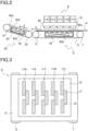
- FIG. 2 is a side sectional view showing a structure of and around a first belt conveyance portion 5, a recording portion 9, and a second belt conveyance portion 12 of the printer 100 according to the present embodiment.
- FIG. 3 is a plan view, as seen from above, of the first belt conveyance portion 5 and the recording portion 9 of the printer 100 according to the present embodiment.
- a sheet feeding cassette 2a which is a sheet storage portion.
- a manual sheet feeding tray 2b is provided at an outer right side face of the printer main body 1.
- a sheet feeding device 3a Downstream of the sheet feeding cassette 2a in a sheet conveyance direction (that is, to the upper right of the sheet feeding cassette 2a in Fig. 1 ), a sheet feeding device 3a is disposed.
- a sheet feeding device 3b Downstream of the manual sheet feeding tray 2b in the sheet conveyance direction (that is, to the left of the manual sheet feeding tray 2b in Fig. 1 ), a sheet feeding device 3b is disposed.
- These sheet feeding devices 3a and 3b each send out sheets P separately one by one.
- a first sheet conveyance path 4a is provided inside the printer 100.
- the first sheet conveyance path 4a is located at a position that is to the upper right of the sheet feeding cassette 2a and that is to the left of the manual sheet feeding tray 2b.
- a sheet P sent out from the sheet feeding cassette 2a passes through the first sheet conveyance path 4a to be conveyed vertically upward along a side face of the printer main body 1.
- a sheet P sent out from the manual sheet feeding tray 2b passes through the first sheet conveyance path 4a to be conveyed substantially horizontally leftward.
- a pair of registration rollers 13 are provided. Closely downstream of the pair of registration rollers 13, the first belt conveyance portion (conveyance portion) 5 and the recording portion 9 are disposed. The pair of registration rollers 13, while correcting skewed feeding of a sheet P, send out the sheet P toward the first belt conveyance portion 5 with timing coordinated with timing of ink ejection operation executed by the recording portion 9.
- a contact image sensor (CIS) 20 for detecting a position of an end part of a sheet P in a width direction (a direction perpendicular to the sheet conveyance direction) thereof.
- the first belt conveyance portion 5 is provided with a first conveyance belt 8 that is an endless belt wound around a first driving roller 6 and a first driven roller 7.
- a sheet P sent out from the pair of registration rollers 13 passes under the recording portion 9 in a state held by suction on a conveyance surface 8a (an upper surface in FIG. 1 ) of the first conveyance belt 8.
- a first sheet suction portion 30 is provided at a position that is inside the first conveyance belt 8 and that is opposite a back side of the conveyance surface 8a of the first conveyance belt 8.
- the first sheet suction portion 30 is provided with a large number of holes 30a for air suction formed in an upper face thereof.
- the first sheet suction portion 30 has a fan 30b disposed inside thereof, and is capable of sucking air downward through the upper face thereof.
- the first conveyance belt 8 is also provided with a large number of vent holes (not shown) for air suction. This configuration allows the first belt conveyance portion 5 to convey a sheet P while holding it by suction on the conveyance surface 8a of the first conveyance belt 8.
- the recording portion 9 performs recording of an image on a sheet P conveyed thereto by being held by suction on the conveyance surface 8a of the first conveyance belt 8.
- the recording portion 9 includes a head housing 10, and five line heads 11C, 11M, 11Y, 11K, and 11R which are supported in the head housing 10.
- the line heads 11C to 11R each have a recording region with a width equal to or larger than a width of the sheet P conveyed, and are supported at such a height that a predetermined interval (1 mm, for example) is left from the conveyance surface 8a of the first conveyance belt 8.
- the operation panel 27 is an operation portion for accepting inputs of various settings. For example, by operating the operation panel 27, an operator can input the size of a sheet P to be set in the sheet feeding cassette 2, that is, the size of a sheet P to be conveyed by the first conveyance belt 8. Further, by operating the operation panel 27, the operator can also input the number of sheets P to be printed and give an instruction to start a print job.
- the operation panel 27 further functions as a notification device (a display portion) that gives notifications regarding the operation status of the printer 100 and, as will be described later, notifications regarding the line heads 11C to 11R and the waste ink collection containers 21C to 21R.
- FIG. 5 is a diagram schematically showing an ink moving path via the line heads 11C to 11R in the printer 100 of the present embodiment.
- the line heads 11C to 11K are connected via ink supply paths 51.
- the ink containers 50C to 50K are each filled with ink of cyan, magenta, yellow, or black, and supply the ink via the ink supply paths 51 to the recording heads 17 in the line heads 11C to 11K.
- the ink containers 50C to 50K are attachable and detachable with respect to the printer main body 1, and when the ink containers 50C to 50K become empty with the ink therein used up, they are replaced with new ink containers 50C to 50K.
- the main control portion 110a by means of the reader/writer module 23, writes color information and ink installation information (here, installation information of the black ink) on the IC chip 53 of the recording head 17 after the replacement (step S6). Thereafter, it is indicated, on the operation panel 27, that there is no recording head 17 present in the line head 11R that is unused (step S7), and the operation of replacing the recording head 17 is finished.
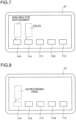
- FIG. 8 is a conceptual diagram of the operation panel 27 indicating that the recording head 17 of the line head 11R has been used.
- the operator after confirming what is indicated on the operation panel 27, opens the exterior cover of the printer main body 1 for access to the waste ink collection containers 21C to 21R attached in the attachment portion 55.
- the main control portion 110a causes the LED lamp 57R, which corresponds to the waste ink collection container 21R, to blink as shown in FIG. 11 .
- the operator according to the blinking of the LED lamp 57R, removes the waste ink collection container 21R.
- the main control portion 110a cancels the indication of the detection of the fullness of the waste ink collection container 21K (step S6). Thereafter, the main control portion 110a indicates, on the operation panel 27, that the waste ink collection container 21R that is unused is absent (step S7), and the operation of replacing the waste ink collection containers 21C to 21R is finished.
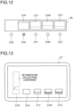
- FIG. 13 is a conceptual diagram of the operation panel 27 indicating that the waste ink collection container 21R has been used.
- waste ink collection container 21R that is unused is used as a replacement for the waste ink collection container 21C, 21M, 21Y, or 21K, it is indicated that the waste ink collection container 21R that is unused is absent, and thus the operator can restock a waste ink collection container 21R in preparation for a next case where the waste ink collection container 21, 21M, 21Y, or 21K becomes full or a case where the line head 11R needs to be used.
- the indication of the detection of the fullness at the attachment position into the on state (turning the LED lamp 57R on) after attaching the full waste ink collection container 21K, it is possible to eliminate the risk of leaving the waste ink collection container 21K without disposing of it. Furthermore, after the waste ink collection container 21K is removed, it is indicated that the waste ink collection container 21R that is unused is absent, and thus the operator can restock a waste ink collection container 21R in preparation for a next case where one of the waste ink collection containers 21C to 21K becomes full or a case where the line head 11R needs to be used.
- the present invention is usable in inkjet recording apparatuses that perform recording by ejecting ink from ink ejection nozzles provided in recording heads. With use of the present invention, it is possible to provide an inkjet recording apparatus in which an unused recording head and an unused waste ink collection container can be made effective use of.
Landscapes
- Ink Jet (AREA)
Abstract
Description
- The present disclosure relates to an inkjet recording apparatus.
- Inkjet recording apparatuses that record an image by ejecting ink from nozzles provided in recording heads are capable of forming a high-definition image and thus have been widely used as recording apparatuses such as facsimile machines, copiers, and printers.
- In such an inkjet recording apparatus, in a case where the maximum number of colors available for use is larger than the number of colors actually used, some recording heads and some waste ink collection containers may be left without being used. In such a case, if an unused recording head or an unused waste ink collection container is left without being used, it is a waste of the component itself and its installation space as well.
-
Patent Document 1 listed below discloses an image recording apparatus that includes a cartridge holding portion that is disposed in a recording head to hold an ink cartridge used in printing, and a waste ink-cartridge storage portion for storing a waste ink tank. In this image recording apparatus, an empty ink cartridge is used as a waste ink tank to store therein waste ink received from a capping member via a waste ink outlet, and when a next empty ink cartridge is discharged from the cartridge holding portion, the waste ink tank is replaced. - As a maintenance method for an unused component, an inkjet recording apparatus disclosed in
Patent Document 2 listed below selectively electrifies an unused cartridge stored in a storage portion and an in-use ink cartridge mounted on a carrier, and, besides electrification for printing, periodically electrifies the unused cartridge stored in the storage portion to thereby perform dummy ejection that does not contribute to printing. -
- Patent Document 1:
Japanese Patent Application Publication No. H07-186401 - Patent Document 2:
Japanese Patent Application Publication No. H08-20113 - With the methods disclosed in
Patent Documents - In view of the above problem, an object of the present invention is to provide an inkjet recording apparatus capable of making effective use of an unused recording head and an unused waste ink collection container.
- To achieve the above object, according to a first configuration of the present invention, an inkjet recording apparatus includes a conveyance portion, a plurality of line heads, a plurality of waste ink collection containers, a display portion, and a control portion. The conveyance portion conveys a sheet. The plurality of line heads each include a recording head that performs image recording by ejecting ink onto the sheet that is conveyed by the conveyance portion. The plurality of waste ink collection containers each collect and store the ink of a corresponding one of different colors that has been ejected from the recording head but has not been used in the image recording. The display portion indicates states of the line heads and the waste ink collection containers. The control portion detects the states of the line heads and the waste ink collection containers and controls display performed by the display portion. Here, in a case where an unused line head exists among the line heads or an unused waste ink collection container exists among the waste ink collection containers and where the recording head in one of the line heads in use or one of the waste ink collection containers in use needs to be replaced, the control portion indicates, on the display portion, the recording head in the unused line head or the unused waste ink collection container as a recording head available for replacement or a waste ink collection container available for replacement.
- According to the first configuration of the present invention, in a case where a recording head in use or a waste ink collection container in use needs to be replaced, it is notified that it can be replaced with an unused recording head or an unused waste ink collection container. Thus, even in a case where no replacement recording head or no replacement waste ink collection container is available at hand, it is possible to continue using the inkjet recording apparatus, and thus to suppress occurrence of down time of the inkjet recording apparatus. Further, the unused recording head and the unused waste ink collection container are made use of without being left unused, and this contributes to effective use of components.
-
-
FIG. 1 is a side sectional view showing an outline of a structure of aprinter 100 according to an embodiment of the present invention; -
FIG. 2 is a side sectional view showing a structure of and around a firstbelt conveyance portion 5, arecording portion 9, and a secondbelt conveyance portion 12 of theprinter 100 according to the present embodiment; -
FIG. 3 is a plan view, as seen from above, of the firstbelt conveyance portion 5 and therecording portion 9 of theprinter 100 according to the present embodiment; -
FIG. 4 is a block diagram showing an example of a control path of theprinter 100 according to the present embodiment; -
FIG. 5 is a diagram schematically showing an ink moving path vialine heads 11C to 11R in theprinter 100 according to the present embodiment; -
FIG. 6 is a flow chart showing an example of a procedure of replacing arecording head 17 executed in theprinter 100 according to the present embodiment; -
FIG. 7 is a conceptual diagram of anoperation panel 27 indicating that arecording head 17 of theline head 11R is available for replacement; -
FIG. 8 is a conceptual diagram of theoperation panel 27 indicating that therecording head 17 of theline head 11R has been used; -
FIG. 9 is a flow chart showing an example of a procedure of replacing wasteink collection containers 21C to 21R executed in theprinter 100 according to the present embodiment; -
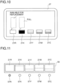
FIG. 10 is a conceptual diagram of theoperation panel 27 indicating that the wasteink collection container 21R is available for replacement; -
FIG. 11 is a front view of the wasteink collection containers 21C to 21R when fullness of the wasteink collection container 21K has been detected; -
FIG. 12 is a front view of anattachment portions 55 for the wasteink collection containers 21C to 21R, with the wasteink collection container 21R removed; -
FIG. 13 is a conceptual diagram of theoperation panel 27 indicating that the wasteink collection container 21R has been used; -
FIG. 14 is a flow chart showing a modified example of the procedure of replacing the wasteink collection containers 21C to 21R executed in theprinter 100 according to the present embodiment; and -
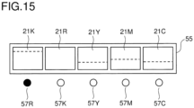
FIG. 15 is a front view of theattachment portion 55 for the wasteink collection containers 21C to 21R, with the full wasteink collection container 21K attached to an original attachment position of the wasteink collection container 21R. - Hereinafter, embodiments of the present invention will be described with reference to the accompanying drawings.
FIG. 1 is a diagram showing an outline of a structure of aprinter 100 according to an embodiment of the present invention.FIG. 2 is a side sectional view showing a structure of and around a firstbelt conveyance portion 5, arecording portion 9, and a secondbelt conveyance portion 12 of theprinter 100 according to the present embodiment.FIG. 3 is a plan view, as seen from above, of the firstbelt conveyance portion 5 and therecording portion 9 of theprinter 100 according to the present embodiment. - As shown in a
FIG. 1 , in theprinter 100, in a lower part inside a printermain body 1 thereof, there is arranged asheet feeding cassette 2a which is a sheet storage portion. At an outer right side face of the printermain body 1, a manualsheet feeding tray 2b is provided. Downstream of thesheet feeding cassette 2a in a sheet conveyance direction (that is, to the upper right of thesheet feeding cassette 2a inFig. 1 ), asheet feeding device 3a is disposed. Downstream of the manualsheet feeding tray 2b in the sheet conveyance direction (that is, to the left of the manualsheet feeding tray 2b inFig. 1 ), asheet feeding device 3b is disposed. Thesesheet feeding devices - Inside the
printer 100, a firstsheet conveyance path 4a is provided. The firstsheet conveyance path 4a is located at a position that is to the upper right of thesheet feeding cassette 2a and that is to the left of the manualsheet feeding tray 2b. A sheet P sent out from thesheet feeding cassette 2a passes through the firstsheet conveyance path 4a to be conveyed vertically upward along a side face of the printermain body 1. A sheet P sent out from the manualsheet feeding tray 2b passes through the firstsheet conveyance path 4a to be conveyed substantially horizontally leftward. - At a downstream end of the first
sheet conveyance path 4a with respect to the sheet conveyance direction, a pair ofregistration rollers 13 are provided. Closely downstream of the pair ofregistration rollers 13, the first belt conveyance portion (conveyance portion) 5 and therecording portion 9 are disposed. The pair ofregistration rollers 13, while correcting skewed feeding of a sheet P, send out the sheet P toward the firstbelt conveyance portion 5 with timing coordinated with timing of ink ejection operation executed by therecording portion 9. - Between the pair of
registration rollers 13 and the firstbelt conveyance portion 5, there is disposed a contact image sensor (CIS) 20 for detecting a position of an end part of a sheet P in a width direction (a direction perpendicular to the sheet conveyance direction) thereof. - The first
belt conveyance portion 5 is provided with afirst conveyance belt 8 that is an endless belt wound around afirst driving roller 6 and a first drivenroller 7. A sheet P sent out from the pair ofregistration rollers 13 passes under therecording portion 9 in a state held by suction on aconveyance surface 8a (an upper surface inFIG. 1 ) of thefirst conveyance belt 8. - At a position that is inside the
first conveyance belt 8 and that is opposite a back side of theconveyance surface 8a of thefirst conveyance belt 8, a firstsheet suction portion 30 is provided. The firstsheet suction portion 30 is provided with a large number ofholes 30a for air suction formed in an upper face thereof. The firstsheet suction portion 30 has afan 30b disposed inside thereof, and is capable of sucking air downward through the upper face thereof. Further, thefirst conveyance belt 8 is also provided with a large number of vent holes (not shown) for air suction. This configuration allows the firstbelt conveyance portion 5 to convey a sheet P while holding it by suction on theconveyance surface 8a of thefirst conveyance belt 8. - The
recording portion 9 performs recording of an image on a sheet P conveyed thereto by being held by suction on theconveyance surface 8a of thefirst conveyance belt 8. As shown inFIGS. 2 and 3 , therecording portion 9 includes ahead housing 10, and five line heads 11C, 11M, 11Y, 11K, and 11R which are supported in thehead housing 10. The line heads 11C to 11R each have a recording region with a width equal to or larger than a width of the sheet P conveyed, and are supported at such a height that a predetermined interval (1 mm, for example) is left from theconveyance surface 8a of thefirst conveyance belt 8. In each of the line heads 11C to 11R, three recording heads 17 are arranged in a staggered array along a sheet width direction (an up-down direction inFIG. 3 ), which is perpendicular to the sheet conveyance direction. In each of the recording heads 17, on an ink ejection surface thereof, a large number ofink ejection nozzles 18 are arranged. The recording heads 17 disposed in the line heads 11C to 11R are all identical in shape and configuration, and thus are interchangeable with each other. - The recording heads 17 constituting the line heads 11C to 11K are supplied with ink of four colors (cyan, magenta, yellow, and black) stored in
ink containers 50C to 50K (seeFIG. 5 ) corresponding to the colors of the line heads 11C to 11K. - Corresponding to information of image data received from an external computer or the like, the line heads 11C to 11K each sequentially eject ink of cyan, magenta, yellow, or black from
ink ejection nozzles 18 of their respective recording heads 17 toward a sheet P attached by suction on thefirst conveyance belt 8. As a result, on the sheet P, a full-color image having ink of the four colors, namely, cyan, magenta, yellow, and black superimposed one on another is formed. Note that theline head 11R is not used. - On a downstream side (a left side in
FIG. 1 ) of the firstbelt conveyance portion 5 with respect to the sheet conveyance direction, the secondbelt conveyance portion 12 is disposed. The sheet P having an image recorded thereon at therecording portion 9 is sent to the secondbelt conveyance portion 12, and the ink which has been ejected onto a surface of the sheet P is dried while the sheet P is passing over the secondbelt conveyance portion 12. - The second
belt conveyance portion 12 includes asecond conveyance belt 40 that is an endless belt wound around asecond driving roller 41 and a second drivenroller 42. Thesecond conveyance belt 40 is caused by thesecond driving roller 41 to rotate counterclockwise inFIG. 2 . The sheet P having an image recorded thereon by therecording unit 9 and conveyed by the firstbelt conveyance portion 5 in an arrow-X direction is transferred to thesecond conveyance belt 40 to be conveyed in an arrow-Z direction inFIG. 2 . - At a position that is inside the
second conveyance belt 40 and that is opposite a back side of aconveyance surface 40a of thesecond conveyance belt 40, a secondsheet suction portion 43 is provided. The secondsheet suction portion 43 is provided with a large number ofholes 43a for air suction formed in an upper face thereof. The secondsheet suction portion 43 is provided with afan 43b disposed inside thereof, and is capable of sucking air downward through the upper face thereof. Thesecond conveyance belt 40 also has a large number of vent holes (not shown) for air suction formed therein. This configuration allows the secondbelt conveyance portion 12 to convey a sheet P while holding the sheet P by suction on theconveyance surface 40a of thesecond conveyance belt 40. - At a position that is on a downstream side of the second
belt conveyance portion 12 with respect to the sheet conveying direction and that is close to a left side face of the printermain body 1, adecurler portion 14 is provided. The sheet P having the ink thereon dried on the secondbelt conveyance portion 12 is sent to thedecurler portion 14, where a curl developed in the sheet P is corrected. - Downstream of (in
FIG. 1 , above) thedecurler portion 14 with respect to the sheet conveying direction, a secondsheet conveyance path 4b is provided. In a case where double-sided recording is not to be performed, after passing through thedecurler portion 14, the sheet P is conveyed through the secondsheet conveyance path 4b, via a pair of discharge rollers, onto asheet discharge tray 15 provided on an outer left side face of theprinter 100. In a case where double-sided recording is to be performed, the sheet P on one side of which recording has been completed passes through the secondbelt conveyance portion 12 and thedecurler portion 14, and then passes through the secondsheet conveyance path 4b to be conveyed into areverse conveyance path 16. In thereverse conveyance path 16, the sheet conveying direction is switched to turn the sheet P upside down, and then the sheet P passes through an upper part of theprinter 100 to be conveyed to the pair ofregistration rollers 13. Thereafter, the sheet P is conveyed, with its unrecorded surface facing up, back to the firstbelt conveyance portion 5. - Under the second
belt conveyance portion 12, amaintenance unit 19 is arranged. When executing maintenance of the recording heads 17, themaintenance unit 19 moves to under therecording portion 9, and wipes off the ink ejected (purged) from theink ejection nozzles 18 of the recording heads 17. -
FIG. 4 is a block diagram showing an example of a control path of theprinter 100 of the present embodiment. In addition to the above-described configurations, theprinter 100 further includes wasteink collection containers 21C to 21R, a reader/writer module 23, anoperation panel 27, astorage 28, and acommunication portion 29. - The waste
ink collection containers 21C to 21R are respectively provided corresponding to the line heads 11C to 11R. The wasteink collection containers 21C to 21R respectively collect ink that has been ejected from the recording heads 17 constituting the line heads 11C to 11R but has not been used in image recording (printing), and store the collected ink therein. Examples of ink that has not been used in image recording include ink ejected in idle ejection (flushing) which is performed for the purpose of preventing clogging of theink ejection nozzles 18 at times other than when image recording is performed, and ink (purge ink) pushed out of theink ejection nozzles 18 in a recovery operation of the recording heads 17 after a long period of disuse. - The reader/
writer module 23 reads and writes information from and onto IC chips 53 (seeFIG. 5 ) mounted on the recording heads 17. In the present invention, radio frequency identification (RFID), in which reading and updating of information regarding ink color and ink installation stored in the IC chips 53 is performed by the reader/writer module 23, is used to determine whether the recording heads 17 are unused or not. - The
operation panel 27 is an operation portion for accepting inputs of various settings. For example, by operating theoperation panel 27, an operator can input the size of a sheet P to be set in thesheet feeding cassette 2, that is, the size of a sheet P to be conveyed by thefirst conveyance belt 8. Further, by operating theoperation panel 27, the operator can also input the number of sheets P to be printed and give an instruction to start a print job. Theoperation panel 27 further functions as a notification device (a display portion) that gives notifications regarding the operation status of theprinter 100 and, as will be described later, notifications regarding the line heads 11C to 11R and the wasteink collection containers 21C to 21R. - The
storage 28 is a memory that stores an operation program for acontrol device 110 and various kinds of information, and is configured by including a read only memory (ROM), a random access memory (RAM), a nonvolatile memory, etc. Information set via theoperation panel 27 is stored in thestorage 28. - The
communication portion 29 is a communication interface for transmitting and receiving information to and from an external device (such as a personal computer (PC)). For example, when the operator operates a PC to transmit a printing command together with image data to theprinter 100, the image data and the printing command is fed to theprinter 100 via thecommunication portion 29. In theprinter 100, amain control portion 110a controls the recording heads 17 of each of the line heads 11C to 11K based on the image data mentioned above and causes the recording heads 17 to eject ink, whereby an image can be recorded on a sheet P. - The
printer 100 of the present embodiment includes thecontrol device 110. Thecontrol device 110 is configured by including, for example, a central processing unit (CPU) and a memory. Specifically, thecontrol device 110 includes themain control portion 110a, aflushing control portion 110b, a sheetfeeding control portion 110c, and amaintenance control portion 110d. - The
main control portion 110a controls operations of various portions of theprinter 100. For example, operations such as driving of various rollers provided inside theprinter 100, ejection of ink from the recording heads 17 during image recording, and the like are controlled by themain control portion 110a. Theflushing control portion 110b drives theink ejection nozzles 18 of the recording heads 17 to execute flushing. For flushing, openings (not shown) are formed in thefirst conveyance belt 8, and during flushing, ink is ejected from theink ejection nozzles 18 with timing coordinated with timing of passing of the openings. - The sheet
feeding control portion 110c is a recording medium feeding control portion that controls the pair ofregistration rollers 13 functioning as a recording medium feeding portion. For example, the sheetfeeding control portion 110c controls the pair ofregistration rollers 13 based on timing when theCIS 20 detects a rear end of a sheet P, and thereby controls timing of conveying a next sheet P. - The
maintenance control portion 110d performs control for causing the recording heads 17 to execute the above-described purging of forcibly pushing the ink out of each of the ink ejection nozzles 18. When causing the recording heads 17 to execute the purging, themaintenance control portion 110d also controls driving of the above-described maintenance unit 19 (for example, movement of themaintenance unit 19 downward of therecording portion 9 and evacuation of themaintenance unit 19 from downward of the recording portion 9). - The
control device 110 may further include a calculation portion that performs necessary calculations and a timer that counts time. Or instead, the functions of the calculation portion and the timer may be executed by themain control portion 110a. -
FIG. 5 is a diagram schematically showing an ink moving path via the line heads 11C to 11R in theprinter 100 of the present embodiment. As shown inFIG. 5 , to theink containers 50C to 50K, the line heads 11C to 11K are connected viaink supply paths 51. Theink containers 50C to 50K are each filled with ink of cyan, magenta, yellow, or black, and supply the ink via theink supply paths 51 to the recording heads 17 in the line heads 11C to 11K. Theink containers 50C to 50K are attachable and detachable with respect to the printermain body 1, and when theink containers 50C to 50K become empty with the ink therein used up, they are replaced withnew ink containers 50C to 50K. - To the recording heads 17, the IC chips 53 are attached. Onto the IC chips 53 attached to the recording heads 17 in the line heads 11C to 11K, at a time when the
printer 100 starts to be used, the reader/writer module 23 (seeFIG. 4 ) writes information regarding ink color and ink installation. - Corresponding to the line heads 11C to 11R, the waste
ink collection containers 21C to 21R are provided. Ink (waste ink) that has not been used in image recording, such as ink ejected in flushing and ink purged, is collected in the wasteink collection containers 21C to 21R via ink receiving portions and ink collection paths (of which none is illustrated) disposed opposite the recording heads 17. The wasteink collection containers 21C to 21R are all identical in shape and structure, and thus are interchangeable with each other. - Here, the
line head 11R is provided as a reserve. In a case of using ink of another color in addition to cyan, magenta, yellow, and black, an ink container of the predetermined color is connected to theline head 11R. In the present embodiment, theline head 11R is unused, and thus no ink container is connected thereto, and the recording heads 17 thereof is in an unused state. Thus, no information regarding either ink color or ink installation has been written on the IC chips 53 attached to the recording heads 17 in theline head 11R. The wasteink collection container 21R is also in an unused (empty) state. - In a case, for example, where one of the recording heads 17 in the line heads 11C to 11K which are in use has failed or where one of the waste
ink collection containers 21C to 21K has become full, the failedrecording head 17 or the full one of the wasteink collection containers 21C to 21K needs to be replaced, but there may be a case where unfortunately no recording head or no waste ink collection container for replacement is available at hand. In such a case, if it can be indicated that therecording head 17 of theline head 11R or the wasteink collection container 21R is available for replacement, it is possible to continue using theprinter 100. Therecording head 17 of theline head 11R and the wasteink collection container 21R, which are unused, can be made effective use of, without being left unused in the printermain body 1. -
FIG. 6 is a flow chart showing an example of a procedure of replacing the recording heads 17 executed in theprinter 100 according to the present embodiment. Referring toFIGS. 1 to 5 and later-describedFIGS. 7 and 8 as necessary, and following the steps shown inFIG. 6 , a description will be given of the procedure of replacing the recording heads 17 in theprinter 100. - The
main control portion 110a determines whether or not failure has occurred in the recording heads 17 of the line heads 11C to 11K in use (step S1). In a case where no failure has occurred (No in step S1), the monitoring of failure is continued. In a case where arecording head 17 of one of the line heads 11C to 11K has failed, (Yes in step S1), themain control portion 110a indicates, on theoperation panel 27, the one (for example, theline head 11K) of the line heads 11C to 11K in which the failure has occurred (step S2). - Next, the
main control portion 110a determines presence/absence of arecording head 17 in theline head 11R that is unused (step S3). The presence/absence of arecording head 17 and whether therecording head 17 is unused or not can be determined by the reader/writer module 23 reading color information stored in theIC chip 53 on therecording head 17 of theline head 11R. - In a case where there is a
recording head 17 in theline head 11R that is unused (Yes in step S3), themain control portion 110a indicates, on theoperation panel 27, therecording head 17 of theline head 11R as arecording head 17 available for replacement (step S4). -
FIG. 7 is a conceptual diagram of theoperation panel 27 indicating that therecording head 17 of theline head 11R is available for replacement. For example, in a case where arecording head 17 of theline head 11K for black has failed, it is indicated that a failure has occurred in theline head 11K, as well as that therecording head 17 of theline head 11R that is unused is available for replacement. The operator confirms what is indicated on theoperation panel 27, and then removes the failedrecording head 17 of theline head 11K to replace it with therecording head 17 of theline head 11R (step S5). - Next, the
main control portion 110a, by means of the reader/writer module 23, writes color information and ink installation information (here, installation information of the black ink) on theIC chip 53 of therecording head 17 after the replacement (step S6). Thereafter, it is indicated, on theoperation panel 27, that there is norecording head 17 present in theline head 11R that is unused (step S7), and the operation of replacing therecording head 17 is finished.FIG. 8 is a conceptual diagram of theoperation panel 27 indicating that therecording head 17 of theline head 11R has been used. - On the other hand, in step S3, in a case where there is no
recording head 17 present in theline head 11R (No in step S3), use of theprinter 100 is prohibited (step S8), and the process is finished. - According to the example of control shown in
FIG. 6 , in a case where one of the recording heads 17 of the line heads 11C to 11K in use has failed, it is notified to the operator that therecording head 17 of theline head 11R that is unused is available for replacement. Thus, even in a case where norecording head 17 for replacement is available at hand, it is possible to continue using theprinter 100, and thus to suppress occurrence of downtime of theprinter 100. Further, therecording head 17 of theline head 11R that is unused is made use of without being left unused, and this contributes to effective use of components. - Furthermore, after the
recording head 17 of theline head 11R that is unused is used as areplacement recording head 17, it is indicated that there is norecording head 17 present in theline head 11R, and thus the operator can restock theline head 11R with new recording heads 17 in preparation for a next failure in theline head line head 11R needs to be used. - Note that, even if no
recording head 17 is attached in theline head 11R, it will have no effect on operations of theprinter 100, and thus it can be freely selected as necessary whether or not to indicate that there is norecording head 17 present in theline head 11R. Further, in a case where a plurality of recording heads 17 available for replacement are attached in theline head 11R, it can be indicated, on theoperation panel 27, that the number of recording heads 17 attached in theline head 11R has been reduced as a result of the replacement. - Next, a description will be given of how to make use of the waste
ink collection container 21R that is unused.FIG. 9 is a flow chart showing an example of a procedure of replacing the wasteink collection containers 21C to 21R executed in theprinter 100 according to the present embodiment. Referring toFIGS. 1 to 5 and later-describedFIGS. 10 to 13 as necessary, and following the steps shown inFIG. 9 , a description will be given of the procedure of replacing the wasteink collection containers 21C to 21R in theprinter 100. - The
main control portion 110a determines whether or not fullness of the wasteink collection containers 21C to 21K in use has been detected (step S1). Examples of a method for detecting the fullness of the wasteink collection containers 21C to 21K include conventionally known methods such as a method where a sensor, for example, is used to directly detect amounts of ink in the wasteink collection containers 21C to 21K, and a method where the amounts of ink are calculated from amounts of ink ejected (numbers of times of ink ejection) from the recording heads 17 of the line heads 11C to 11K except during image recording. - In a case where none of the waste
ink collection containers 21C to 21K has been detected to be full (No in step S 1), monitoring for the detection of fullness is continued. In a case where fullness of one of the wasteink collection containers 21C to 21K has been detected (Yes in step S 1), themain control portion 110a indicates, on theoperation panel 27, the one of the wasteink collection containers 21C to 21K (for example, the wasteink collection container 21K) that has been detected to be full (step S2). - Next, the
main control portion 110a determines presence/absence of the wasteink collection container 21R that is unused (step S3). The presence/absence of the wasteink collection container 21R can be detected, for example, by using a sensor (unillustrated) provided in the attachment portion 55 (seeFIG. 11 ) where the wasteink collection container 21R is attached. - In a case where the waste
ink collection container 21R that is unused is present (Yes in step S3), themain control portion 110a indicates, on theoperation panel 27, the wasteink collection container 21R as a waste ink collection container available for replacement (step S4). -
FIG. 10 is a conceptual diagram of theoperation panel 27 indicating that the wasteink collection container 21R is available for replacement. For example, in a case where it has been detected that the wasteink collection container 21K for black is full, it is indicated that the wasteink collection container 21K is full and that the wasteink collection container 21R that is unused is available for replacement. -
FIG. 11 is a front view of theattachment portion 55 for the wasteink collection containers 21C to 21R when it has been detected that the wasteink collection container 21K is full. Theattachment portion 55 is provided inside an exterior cover (unillustrated) of the printermain body 1. Close to theattachment portion 55,LED lamps 57C to 57R are disposed corresponding to the wasteink collection containers 21C to 21R. - The operator, after confirming what is indicated on the
operation panel 27, opens the exterior cover of the printermain body 1 for access to the wasteink collection containers 21C to 21R attached in theattachment portion 55. At this time, themain control portion 110a causes theLED lamp 57R, which corresponds to the wasteink collection container 21R, to blink as shown inFIG. 11 . The operator, according to the blinking of theLED lamp 57R, removes the wasteink collection container 21R. -
FIG. 12 is a front view of theattachment portion 55 for attaching the wasteink collection containers 21C to 21R, with the wasteink collection container 21R removed. After the wasteink collection container 21R is removed, themain control portion 110a turns off the blinking of theLED lamp 57R, and causes theLED lamp 57K corresponding to the wasteink collection container 21 K that is full to start blinking. The operator, according to the blinking of theLED lamp 57R, removes the wasteink collection container 21K to replace it with the wasteink collection container 21R (step S5). - Next, the
main control portion 110a cancels the indication of the detection of the fullness of the wasteink collection container 21K (step S6). Thereafter, themain control portion 110a indicates, on theoperation panel 27, that the wasteink collection container 21R that is unused is absent (step S7), and the operation of replacing the wasteink collection containers 21C to 21R is finished.FIG. 13 is a conceptual diagram of theoperation panel 27 indicating that the wasteink collection container 21R has been used. - On the other hand, in a case where, in step S3, the waste
ink collection container 21R that is unused is absent (No in step S3), the use of theprinter 100 is prohibited (step S8) and the process is finished. - According to the example of control shown in
FIG. 9 , in a case where one of the wasteink collection containers 21C to 21K in use has become full, it is notified to the operator that the wasteink collection container 21R that is unused is available for replacement. Thus, even in a case where wasteink collection containers 21C to 21K for replacement are not available at hand, it is possible to continue using theprinter 100, and thus it is possible to suppress occurrence of downtime of theprinter 100. Further, the wasteink collection container 21R that is unused is made use of without being left unused, and this contributes to effective use of components. - The procedure of replacing the waste
ink collection containers 21C to 21R is indicated by means of the blinking of theLED lamps 57C to 57R, and this makes it possible for the operator to smoothly proceed with the operation of replacing a full one of the wasteink collection containers 21C to 21K, without any risk of following a wrong procedure or erroneously replacing one of the wasteink collection containers 21C to 21K that does not need to be replaced. - Furthermore, after the waste
ink collection container 21R that is unused is used as a replacement for the wasteink collection container ink collection container 21R that is unused is absent, and thus the operator can restock a wasteink collection container 21R in preparation for a next case where the wasteink collection container line head 11R needs to be used. - Note that, even if no waste
ink collection container 21R is attached, it will have no effect on operations of theprinter 100, and thus it can be freely selected as necessary whether or not to indicate that the wasteink collection container 21R is absent. Further, in a case where a plurality of wasteink collection containers 21R that are unused are attached, theoperation panel 27 may indicate that the number of the wasteink collection containers 21R has been reduced as a result of the replacement. -
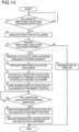
FIG. 14 is a flow chart showing a modified example of the procedure of replacing the wasteink collection containers 21C to 21R executed in theprinter 100 according to the present embodiment. In the modified example shown inFIG. 14 , the wasteink collection container 21K of which fullness has been detected is removed and replaced with the wasteink collection container 21R that is unused (step S5), and thereafter, the wasteink collection container 21K, which has become full, is attached to the original attachment position of the wasteink collection container 21R (step S6). Then, the indication of the detection of the fullness at the attachment position of the wasteink collection container 21K is brought into an on state (step S7). -
FIG. 15 is a front view of theattachment portion 55 for the wasteink collection containers 21C to 21R, with the wasteink collection container 21K, which has become full, attached to the original attachment position of the wasteink collection container 21R. As shown inFIG. 15 , theLED lamp 57R that corresponds to the attachment position of the wasteink collection container 21K (the original attachment position of the wasteink collection container 21R) is turned on. - Next, the
main control portion 110a determines whether or not the wasteink collection container 21K, which is full. has been removed (step S8). In a case where the wasteink collection container 21K has not been removed (No in step S8), the on state of the indication of the detection of the fullness at the attachment position (the on state of theLED lamp 57R) is continued. In a case where the wasteink collection container 21K has been removed (Yes in step S8), the indication of the detection of the fullness at the attachment position is brought into an off state (theLED lamp 57R is turned off) (step S9). Thereafter, as shown inFIG. 13 , it is indicated, on theoperation panel 27, that the wasteink collection container 21R that is unused is absent (step S10), and the operation of replacing the wasteink collection containers 21C to 21R is finished. Steps in the procedure other than those described above are the same as inFIG. 9 , and thus overlapping descriptions thereof are omitted. - According to the example of control shown in
FIG. 14 , the wasteink collection container 21K, which has become full, is attached to the original attachment position of the wasteink collection container 21R where it was attached when it was unused. Thereby, in a case where there is no time to dispose of the wasteink collection container 21K or no space for storing it, the original attachment position of the wasteink collection container 21R that is now used as a replacement can be effectively used as a temporary storage space for the wasteink collection container 21K. - Further, by bringing the indication of the detection of the fullness at the attachment position into the on state (turning the
LED lamp 57R on) after attaching the full wasteink collection container 21K, it is possible to eliminate the risk of leaving the wasteink collection container 21K without disposing of it. Furthermore, after the wasteink collection container 21K is removed, it is indicated that the wasteink collection container 21R that is unused is absent, and thus the operator can restock a wasteink collection container 21R in preparation for a next case where one of the wasteink collection containers 21C to 21K becomes full or a case where theline head 11R needs to be used. - Note that, even if no waste
ink collection container 21R is attached, it will have no effect on operations of theprinter 100, and thus it can be freely selected as necessary whether or not to indicate that the wasteink collection container 21R is absent. Here, in a case where a plurality of wasteink collection containers 21R that are unused are attached, theoperation panel 27 may indicate that the number of the wasteink collection containers 21R has been reduced as a result of the replacement. - The embodiment described above is in no way meant to limit the present invention, which thus allows for many modifications and variations within the spirit of the present invention. For example, although the above embodiment has dealt with an example where the five line heads 11C to 11R are provided among which the four line heads 11C to 11K are in use, the present invention is applicable as long as at least one line head that is unused is present, and thus the total number of the line heads and the number of the line heads in use can be freely set as necessary.
- There is no particular limitation to the number of recording heads 17 in each of the line heads 11C to 11R, and, for example, one
recording head 17, two recording heads 17, or four or more recording heads 17 may be disposed in each of the line heads 11C to 11K. - In the above embodiment, both the
operation panel 27 and theLED lamps 57C to 57R are used to indicate the states of the recording heads 17 and the wasteink collection containers 21C to 21R, but it is also possible to indicate the states by using either theoperation panel 27 or theLED lamps 57C to 57R. - The present invention is usable in inkjet recording apparatuses that perform recording by ejecting ink from ink ejection nozzles provided in recording heads. With use of the present invention, it is possible to provide an inkjet recording apparatus in which an unused recording head and an unused waste ink collection container can be made effective use of.
Claims (7)
- An inkjet recording apparatus, comprising:a conveyance portion that conveys a sheet;a plurality of line heads each including a recording head that performs image recording by ejecting ink onto the sheet conveyed by the conveyance portion;a plurality of waste ink collection containers that each collect and store the ink of a corresponding one of different colors that has been ejected from the recording head but has not been used in the image recording;a display portion that indicates states of the line heads and the waste ink collection containers; anda control portion that detects the states of the line heads and the waste ink collection containers and controls display performed by the display portion,whereinin a case where an unused line head exists among the line heads or an unused waste ink collection container exists among the waste ink collection containers and where the recording head in one of the line heads in use or one of the waste ink collection containers in use needs to be replaced, the control portion indicates, on the display portion, the recording head in the unused line head or the unused waste ink collection container as a recording head available for replacement or a waste ink collection container available for replacement.
- The inkjet recording apparatus according to claim 1,
whereinthe recording head has mounted thereon an external memory that is nonvolatile and that stores color information of the ink and information regarding installation of the ink, andin a case where the recording head in one line head among the line heads in use has been replaced with the recording head that is unused, the control portion writes, on the external memory mounted on the recording head that is unused, the color information of the ink and the information regarding installation of the ink in the one line head. - The inkjet recording apparatus according to claim 1,
wherein
in a case where the unused waste ink collection container exists and fullness of one waste ink collection container among the waste ink collection containers in use has been detected, the control portion uses the display portion to indicate a procedure of replacing the waste ink collection containers. - The inkjet recording apparatus according to claim 1,
wherein
one waste ink collection container among the waste ink collection containers that has become full is temporarily placeable in a position from which the unused waste ink collection container has been removed. - The inkjet recording apparatus according to claim 4,
wherein
in a case where the one waste ink collection container that has become full is temporarily placed in the position from which the unused waste ink collection container has been removed, the control portion uses the display portion to indicate that the waste ink collection container that is temporarily placed is full. - The inkjet recording apparatus according to claim 5,
wherein
in a case where the waste ink collection container that is temporarily placed is removed, the control portion deletes the indication that the waste ink collection container that is temporarily placed is full. - The inkjet recording apparatus according to claim 1,
wherein
in a case where the recording head that is unused or the unused waste ink collection container is used, the control portion uses the display portion to indicate that no recording head or no waste ink collection container is available for replacement, or that a number of recording heads available for replacement or a number of waste ink collection containers available for replacement has been reduced.
Applications Claiming Priority (2)
| Application Number | Priority Date | Filing Date | Title |
|---|---|---|---|
| JP2021141439 | 2021-08-31 | ||
| PCT/JP2022/032510 WO2023032951A1 (en) | 2021-08-31 | 2022-08-30 | Inkjet recording device |
Publications (2)
| Publication Number | Publication Date |
|---|---|
| EP4397494A1 true EP4397494A1 (en) | 2024-07-10 |
| EP4397494A4 EP4397494A4 (en) | 2025-08-13 |
Family
ID=85411272
Family Applications (1)
| Application Number | Title | Priority Date | Filing Date |
|---|---|---|---|
| EP22864533.9A Pending EP4397494A4 (en) | 2021-08-31 | 2022-08-30 | INKJET RECORDING DEVICE |
Country Status (5)
| Country | Link |
|---|---|
| US (1) | US12521990B2 (en) |
| EP (1) | EP4397494A4 (en) |
| JP (1) | JP7622855B2 (en) |
| CN (1) | CN117881545A (en) |
| WO (1) | WO2023032951A1 (en) |
Family Cites Families (22)
| Publication number | Priority date | Publication date | Assignee | Title |
|---|---|---|---|---|
| JPH0820113B2 (en) | 1993-03-08 | 1996-03-04 | リンナイ株式会社 | Water heater |
| JP3233762B2 (en) | 1993-12-27 | 2001-11-26 | 京セラミタ株式会社 | Image recording device |
| JP3410216B2 (en) | 1994-07-06 | 2003-05-26 | 東芝テック株式会社 | Inkjet printer |
| US5587730A (en) | 1994-09-30 | 1996-12-24 | Xerox Corporation | Redundant full width array thermal ink jet printing for improved reliability |
| US7029105B2 (en) * | 2002-02-15 | 2006-04-18 | Matsushita Electric Industrial Co., Ltd. | Ink-jet recording device and control method thereof |
| JP2004130701A (en) * | 2002-10-11 | 2004-04-30 | Riso Kagaku Corp | INK JET PRINTING APPARATUS AND CONTROL METHOD OF INK JET PRINTING APPARATUS |
| JP2004195799A (en) * | 2002-12-18 | 2004-07-15 | Ricoh Co Ltd | Liquid circulation device, droplet discharge device, and inkjet recording device using the droplet discharge device |
| JP2004276387A (en) * | 2003-03-14 | 2004-10-07 | Fuji Photo Film Co Ltd | Ink jet recorder |
| US6871926B2 (en) * | 2003-04-18 | 2005-03-29 | Lexmark International, Inc. | Method of estimating an amount of available ink contained in an ink reservoir |
| JP4218477B2 (en) * | 2003-09-19 | 2009-02-04 | 富士ゼロックス株式会社 | Inkjet recording device |
| US7347542B2 (en) * | 2004-06-25 | 2008-03-25 | Xerox Corporation | Apparatus and method for waste ink disposal in solid ink jet printer |
| JP2006297731A (en) * | 2005-04-20 | 2006-11-02 | Canon Inc | Ink jet recording apparatus, method for preventing erroneous mounting of recording head, and control program therefor |
| JP2006305902A (en) | 2005-04-28 | 2006-11-09 | Brother Ind Ltd | Inkjet recording device |
| CN101923477B (en) * | 2009-06-12 | 2014-04-23 | 精工爱普生株式会社 | Operation support method |
| JP2011016255A (en) | 2009-07-07 | 2011-01-27 | Canon Inc | Ink-jet recording device |
| KR101708452B1 (en) * | 2016-08-08 | 2017-03-08 | 장준형 | Device for Recycling Waste Ink by Printer |
| JP7005942B2 (en) | 2017-06-01 | 2022-01-24 | 京セラドキュメントソリューションズ株式会社 | Waste ink storage mechanism and inkjet recording device equipped with it |
| JP2019006089A (en) | 2017-06-28 | 2019-01-17 | キヤノン株式会社 | Control device, control method and program |
| CN110356110B (en) * | 2018-03-26 | 2021-10-08 | 京瓷办公信息系统株式会社 | Liquid supply unit and liquid ejection device |
| JP7107016B2 (en) * | 2018-06-20 | 2022-07-27 | 京セラドキュメントソリューションズ株式会社 | Inkjet recording device |
| JP7314541B2 (en) * | 2019-03-13 | 2023-07-26 | セイコーエプソン株式会社 | liquid injector |
| JP7380056B2 (en) * | 2019-10-11 | 2023-11-15 | 京セラドキュメントソリューションズ株式会社 | inkjet recording device |
-
2022
- 2022-08-30 EP EP22864533.9A patent/EP4397494A4/en active Pending
- 2022-08-30 US US18/686,676 patent/US12521990B2/en active Active
- 2022-08-30 WO PCT/JP2022/032510 patent/WO2023032951A1/en not_active Ceased
- 2022-08-30 JP JP2023545584A patent/JP7622855B2/en active Active
- 2022-08-30 CN CN202280058034.9A patent/CN117881545A/en active Pending
Also Published As
| Publication number | Publication date |
|---|---|
| WO2023032951A1 (en) | 2023-03-09 |
| US20240359472A1 (en) | 2024-10-31 |
| JPWO2023032951A1 (en) | 2023-03-09 |
| US12521990B2 (en) | 2026-01-13 |
| JP7622855B2 (en) | 2025-01-28 |
| EP4397494A4 (en) | 2025-08-13 |
| CN117881545A (en) | 2024-04-12 |
Similar Documents
| Publication | Publication Date | Title |
|---|---|---|
| JP4077953B2 (en) | Print mode adjustment method and printer | |
| KR100578500B1 (en) | Identification of Printed Record Containers | |
| JP2011056721A (en) | Image forming apparatus, method for determining propriety of printing, and program | |
| US8272731B2 (en) | Image forming apparatus | |
| CN103029434B (en) | Media processing device and control method for media processing device | |
| JP6922362B2 (en) | Printing device and control method of printing device | |
| CN101462422A (en) | Printing apparatus and method of controlling printing apparatus | |
| JP2021062533A (en) | Inkjet recording device | |
| CN109249718B (en) | Printing method and printing apparatus | |
| US12521990B2 (en) | Inkjet recording apparatus | |
| JP5258182B2 (en) | Ink jet printer, ink charging system, and control method of ink jet printer | |
| JP2010264672A (en) | Printing system | |
| JP6435225B2 (en) | Consumables information communication system for printing apparatus | |
| JP2004050503A (en) | Inkjet imaging apparatus | |
| JP4805690B2 (en) | Image forming apparatus | |
| US20090167801A1 (en) | Ink-jet recording apparatus | |
| KR100225083B1 (en) | Carriage controlling apparatus and the method thereof | |
| JP2006297731A (en) | Ink jet recording apparatus, method for preventing erroneous mounting of recording head, and control program therefor | |
| US11789391B2 (en) | Image forming apparatus | |
| JP2006198924A (en) | Inkjet recording apparatus, control method, program, and recording medium | |
| JP5332579B2 (en) | Image forming apparatus and head unit control method for image forming apparatus | |
| JP2016049657A (en) | Inkjet recording device | |
| JP2024049586A (en) | Image forming device | |
| JP2016190429A (en) | Consumable supply information communication system of printer | |
| JP2023173171A (en) | Image formation device, image formation method, control device, and program |
Legal Events
| Date | Code | Title | Description |
|---|---|---|---|
| STAA | Information on the status of an ep patent application or granted ep patent |
Free format text: STATUS: THE INTERNATIONAL PUBLICATION HAS BEEN MADE |
|
| PUAI | Public reference made under article 153(3) epc to a published international application that has entered the european phase |
Free format text: ORIGINAL CODE: 0009012 |
|
| STAA | Information on the status of an ep patent application or granted ep patent |
Free format text: STATUS: REQUEST FOR EXAMINATION WAS MADE |
|
| 17P | Request for examination filed |
Effective date: 20240229 |
|
| AK | Designated contracting states |
Kind code of ref document: A1 Designated state(s): AL AT BE BG CH CY CZ DE DK EE ES FI FR GB GR HR HU IE IS IT LI LT LU LV MC MK MT NL NO PL PT RO RS SE SI SK SM TR |
|
| DAV | Request for validation of the european patent (deleted) | ||
| DAX | Request for extension of the european patent (deleted) | ||
| A4 | Supplementary search report drawn up and despatched |
Effective date: 20250714 |
|
| RIC1 | Information provided on ipc code assigned before grant |
Ipc: B41J 2/17 20060101AFI20250708BHEP Ipc: B41J 2/01 20060101ALI20250708BHEP |