EP4397482A1 - Laminated glass and head-up display system - Google Patents
Laminated glass and head-up display system Download PDFInfo
- Publication number
- EP4397482A1 EP4397482A1 EP22877960.9A EP22877960A EP4397482A1 EP 4397482 A1 EP4397482 A1 EP 4397482A1 EP 22877960 A EP22877960 A EP 22877960A EP 4397482 A1 EP4397482 A1 EP 4397482A1
- Authority
- EP
- European Patent Office
- Prior art keywords
- region
- projection
- light
- laminated glass
- image
- Prior art date
- Legal status (The legal status is an assumption and is not a legal conclusion. Google has not performed a legal analysis and makes no representation as to the accuracy of the status listed.)
- Pending
Links
Images





Classifications
-
- G—PHYSICS
- G02—OPTICS
- G02B—OPTICAL ELEMENTS, SYSTEMS OR APPARATUS
- G02B27/00—Optical systems or apparatus not provided for by any of the groups G02B1/00 - G02B26/00, G02B30/00
- G02B27/01—Head-up displays
- G02B27/0101—Head-up displays characterised by optical features
-
- B—PERFORMING OPERATIONS; TRANSPORTING
- B32—LAYERED PRODUCTS
- B32B—LAYERED PRODUCTS, i.e. PRODUCTS BUILT-UP OF STRATA OF FLAT OR NON-FLAT, e.g. CELLULAR OR HONEYCOMB, FORM
- B32B17/00—Layered products essentially comprising sheet glass, or glass, slag, or like fibres
- B32B17/06—Layered products essentially comprising sheet glass, or glass, slag, or like fibres comprising glass as the main or only constituent of a layer, next to another layer of a specific material
- B32B17/10—Layered products essentially comprising sheet glass, or glass, slag, or like fibres comprising glass as the main or only constituent of a layer, next to another layer of a specific material of synthetic resin
- B32B17/10005—Layered products essentially comprising sheet glass, or glass, slag, or like fibres comprising glass as the main or only constituent of a layer, next to another layer of a specific material of synthetic resin laminated safety glass or glazing
- B32B17/10165—Functional features of the laminated safety glass or glazing
- B32B17/10431—Specific parts for the modulation of light incorporated into the laminated safety glass or glazing
-
- B—PERFORMING OPERATIONS; TRANSPORTING
- B32—LAYERED PRODUCTS
- B32B—LAYERED PRODUCTS, i.e. PRODUCTS BUILT-UP OF STRATA OF FLAT OR NON-FLAT, e.g. CELLULAR OR HONEYCOMB, FORM
- B32B15/00—Layered products comprising a layer of metal
- B32B15/04—Layered products comprising a layer of metal comprising metal as the main or only constituent of a layer, which is next to another layer of the same or of a different material
- B32B15/08—Layered products comprising a layer of metal comprising metal as the main or only constituent of a layer, which is next to another layer of the same or of a different material of synthetic resin
- B32B15/082—Layered products comprising a layer of metal comprising metal as the main or only constituent of a layer, which is next to another layer of the same or of a different material of synthetic resin comprising vinyl resins; comprising acrylic resins
-
- B—PERFORMING OPERATIONS; TRANSPORTING
- B32—LAYERED PRODUCTS
- B32B—LAYERED PRODUCTS, i.e. PRODUCTS BUILT-UP OF STRATA OF FLAT OR NON-FLAT, e.g. CELLULAR OR HONEYCOMB, FORM
- B32B15/00—Layered products comprising a layer of metal
- B32B15/04—Layered products comprising a layer of metal comprising metal as the main or only constituent of a layer, which is next to another layer of the same or of a different material
- B32B15/08—Layered products comprising a layer of metal comprising metal as the main or only constituent of a layer, which is next to another layer of the same or of a different material of synthetic resin
- B32B15/09—Layered products comprising a layer of metal comprising metal as the main or only constituent of a layer, which is next to another layer of the same or of a different material of synthetic resin comprising polyesters
-
- B—PERFORMING OPERATIONS; TRANSPORTING
- B32—LAYERED PRODUCTS
- B32B—LAYERED PRODUCTS, i.e. PRODUCTS BUILT-UP OF STRATA OF FLAT OR NON-FLAT, e.g. CELLULAR OR HONEYCOMB, FORM
- B32B17/00—Layered products essentially comprising sheet glass, or glass, slag, or like fibres
- B32B17/06—Layered products essentially comprising sheet glass, or glass, slag, or like fibres comprising glass as the main or only constituent of a layer, next to another layer of a specific material
-
- B—PERFORMING OPERATIONS; TRANSPORTING
- B32—LAYERED PRODUCTS
- B32B—LAYERED PRODUCTS, i.e. PRODUCTS BUILT-UP OF STRATA OF FLAT OR NON-FLAT, e.g. CELLULAR OR HONEYCOMB, FORM
- B32B17/00—Layered products essentially comprising sheet glass, or glass, slag, or like fibres
- B32B17/06—Layered products essentially comprising sheet glass, or glass, slag, or like fibres comprising glass as the main or only constituent of a layer, next to another layer of a specific material
- B32B17/061—Layered products essentially comprising sheet glass, or glass, slag, or like fibres comprising glass as the main or only constituent of a layer, next to another layer of a specific material of metal
-
- B—PERFORMING OPERATIONS; TRANSPORTING
- B32—LAYERED PRODUCTS
- B32B—LAYERED PRODUCTS, i.e. PRODUCTS BUILT-UP OF STRATA OF FLAT OR NON-FLAT, e.g. CELLULAR OR HONEYCOMB, FORM
- B32B17/00—Layered products essentially comprising sheet glass, or glass, slag, or like fibres
- B32B17/06—Layered products essentially comprising sheet glass, or glass, slag, or like fibres comprising glass as the main or only constituent of a layer, next to another layer of a specific material
- B32B17/10—Layered products essentially comprising sheet glass, or glass, slag, or like fibres comprising glass as the main or only constituent of a layer, next to another layer of a specific material of synthetic resin
-
- B—PERFORMING OPERATIONS; TRANSPORTING
- B32—LAYERED PRODUCTS
- B32B—LAYERED PRODUCTS, i.e. PRODUCTS BUILT-UP OF STRATA OF FLAT OR NON-FLAT, e.g. CELLULAR OR HONEYCOMB, FORM
- B32B17/00—Layered products essentially comprising sheet glass, or glass, slag, or like fibres
- B32B17/06—Layered products essentially comprising sheet glass, or glass, slag, or like fibres comprising glass as the main or only constituent of a layer, next to another layer of a specific material
- B32B17/10—Layered products essentially comprising sheet glass, or glass, slag, or like fibres comprising glass as the main or only constituent of a layer, next to another layer of a specific material of synthetic resin
- B32B17/10005—Layered products essentially comprising sheet glass, or glass, slag, or like fibres comprising glass as the main or only constituent of a layer, next to another layer of a specific material of synthetic resin laminated safety glass or glazing
-
- B—PERFORMING OPERATIONS; TRANSPORTING
- B32—LAYERED PRODUCTS
- B32B—LAYERED PRODUCTS, i.e. PRODUCTS BUILT-UP OF STRATA OF FLAT OR NON-FLAT, e.g. CELLULAR OR HONEYCOMB, FORM
- B32B17/00—Layered products essentially comprising sheet glass, or glass, slag, or like fibres
- B32B17/06—Layered products essentially comprising sheet glass, or glass, slag, or like fibres comprising glass as the main or only constituent of a layer, next to another layer of a specific material
- B32B17/10—Layered products essentially comprising sheet glass, or glass, slag, or like fibres comprising glass as the main or only constituent of a layer, next to another layer of a specific material of synthetic resin
- B32B17/10005—Layered products essentially comprising sheet glass, or glass, slag, or like fibres comprising glass as the main or only constituent of a layer, next to another layer of a specific material of synthetic resin laminated safety glass or glazing
- B32B17/10009—Layered products essentially comprising sheet glass, or glass, slag, or like fibres comprising glass as the main or only constituent of a layer, next to another layer of a specific material of synthetic resin laminated safety glass or glazing characterized by the number, the constitution or treatment of glass sheets
- B32B17/10036—Layered products essentially comprising sheet glass, or glass, slag, or like fibres comprising glass as the main or only constituent of a layer, next to another layer of a specific material of synthetic resin laminated safety glass or glazing characterized by the number, the constitution or treatment of glass sheets comprising two outer glass sheets
-
- B—PERFORMING OPERATIONS; TRANSPORTING
- B32—LAYERED PRODUCTS
- B32B—LAYERED PRODUCTS, i.e. PRODUCTS BUILT-UP OF STRATA OF FLAT OR NON-FLAT, e.g. CELLULAR OR HONEYCOMB, FORM
- B32B17/00—Layered products essentially comprising sheet glass, or glass, slag, or like fibres
- B32B17/06—Layered products essentially comprising sheet glass, or glass, slag, or like fibres comprising glass as the main or only constituent of a layer, next to another layer of a specific material
- B32B17/10—Layered products essentially comprising sheet glass, or glass, slag, or like fibres comprising glass as the main or only constituent of a layer, next to another layer of a specific material of synthetic resin
- B32B17/10005—Layered products essentially comprising sheet glass, or glass, slag, or like fibres comprising glass as the main or only constituent of a layer, next to another layer of a specific material of synthetic resin laminated safety glass or glazing
- B32B17/10165—Functional features of the laminated safety glass or glazing
- B32B17/10174—Coatings of a metallic or dielectric material on a constituent layer of glass or polymer
- B32B17/10183—Coatings of a metallic or dielectric material on a constituent layer of glass or polymer being not continuous, e.g. in edge regions
-
- B—PERFORMING OPERATIONS; TRANSPORTING
- B32—LAYERED PRODUCTS
- B32B—LAYERED PRODUCTS, i.e. PRODUCTS BUILT-UP OF STRATA OF FLAT OR NON-FLAT, e.g. CELLULAR OR HONEYCOMB, FORM
- B32B17/00—Layered products essentially comprising sheet glass, or glass, slag, or like fibres
- B32B17/06—Layered products essentially comprising sheet glass, or glass, slag, or like fibres comprising glass as the main or only constituent of a layer, next to another layer of a specific material
- B32B17/10—Layered products essentially comprising sheet glass, or glass, slag, or like fibres comprising glass as the main or only constituent of a layer, next to another layer of a specific material of synthetic resin
- B32B17/10005—Layered products essentially comprising sheet glass, or glass, slag, or like fibres comprising glass as the main or only constituent of a layer, next to another layer of a specific material of synthetic resin laminated safety glass or glazing
- B32B17/10165—Functional features of the laminated safety glass or glazing
- B32B17/10339—Specific parts of the laminated safety glass or glazing being colored or tinted
- B32B17/10348—Specific parts of the laminated safety glass or glazing being colored or tinted comprising an obscuration band
-
- B—PERFORMING OPERATIONS; TRANSPORTING
- B32—LAYERED PRODUCTS
- B32B—LAYERED PRODUCTS, i.e. PRODUCTS BUILT-UP OF STRATA OF FLAT OR NON-FLAT, e.g. CELLULAR OR HONEYCOMB, FORM
- B32B17/00—Layered products essentially comprising sheet glass, or glass, slag, or like fibres
- B32B17/06—Layered products essentially comprising sheet glass, or glass, slag, or like fibres comprising glass as the main or only constituent of a layer, next to another layer of a specific material
- B32B17/10—Layered products essentially comprising sheet glass, or glass, slag, or like fibres comprising glass as the main or only constituent of a layer, next to another layer of a specific material of synthetic resin
- B32B17/10005—Layered products essentially comprising sheet glass, or glass, slag, or like fibres comprising glass as the main or only constituent of a layer, next to another layer of a specific material of synthetic resin laminated safety glass or glazing
- B32B17/10165—Functional features of the laminated safety glass or glazing
- B32B17/10339—Specific parts of the laminated safety glass or glazing being colored or tinted
- B32B17/10357—Specific parts of the laminated safety glass or glazing being colored or tinted comprising a tinted intermediate film
-
- B—PERFORMING OPERATIONS; TRANSPORTING
- B32—LAYERED PRODUCTS
- B32B—LAYERED PRODUCTS, i.e. PRODUCTS BUILT-UP OF STRATA OF FLAT OR NON-FLAT, e.g. CELLULAR OR HONEYCOMB, FORM
- B32B17/00—Layered products essentially comprising sheet glass, or glass, slag, or like fibres
- B32B17/06—Layered products essentially comprising sheet glass, or glass, slag, or like fibres comprising glass as the main or only constituent of a layer, next to another layer of a specific material
- B32B17/10—Layered products essentially comprising sheet glass, or glass, slag, or like fibres comprising glass as the main or only constituent of a layer, next to another layer of a specific material of synthetic resin
- B32B17/10005—Layered products essentially comprising sheet glass, or glass, slag, or like fibres comprising glass as the main or only constituent of a layer, next to another layer of a specific material of synthetic resin laminated safety glass or glazing
- B32B17/10165—Functional features of the laminated safety glass or glazing
- B32B17/10431—Specific parts for the modulation of light incorporated into the laminated safety glass or glazing
- B32B17/10467—Variable transmission
- B32B17/10495—Variable transmission optoelectronic, i.e. optical valve
-
- B—PERFORMING OPERATIONS; TRANSPORTING
- B32—LAYERED PRODUCTS
- B32B—LAYERED PRODUCTS, i.e. PRODUCTS BUILT-UP OF STRATA OF FLAT OR NON-FLAT, e.g. CELLULAR OR HONEYCOMB, FORM
- B32B17/00—Layered products essentially comprising sheet glass, or glass, slag, or like fibres
- B32B17/06—Layered products essentially comprising sheet glass, or glass, slag, or like fibres comprising glass as the main or only constituent of a layer, next to another layer of a specific material
- B32B17/10—Layered products essentially comprising sheet glass, or glass, slag, or like fibres comprising glass as the main or only constituent of a layer, next to another layer of a specific material of synthetic resin
- B32B17/10005—Layered products essentially comprising sheet glass, or glass, slag, or like fibres comprising glass as the main or only constituent of a layer, next to another layer of a specific material of synthetic resin laminated safety glass or glazing
- B32B17/1055—Layered products essentially comprising sheet glass, or glass, slag, or like fibres comprising glass as the main or only constituent of a layer, next to another layer of a specific material of synthetic resin laminated safety glass or glazing characterized by the resin layer, i.e. interlayer
- B32B17/10651—Layered products essentially comprising sheet glass, or glass, slag, or like fibres comprising glass as the main or only constituent of a layer, next to another layer of a specific material of synthetic resin laminated safety glass or glazing characterized by the resin layer, i.e. interlayer comprising colorants, e.g. dyes or pigments
-
- B—PERFORMING OPERATIONS; TRANSPORTING
- B32—LAYERED PRODUCTS
- B32B—LAYERED PRODUCTS, i.e. PRODUCTS BUILT-UP OF STRATA OF FLAT OR NON-FLAT, e.g. CELLULAR OR HONEYCOMB, FORM
- B32B17/00—Layered products essentially comprising sheet glass, or glass, slag, or like fibres
- B32B17/06—Layered products essentially comprising sheet glass, or glass, slag, or like fibres comprising glass as the main or only constituent of a layer, next to another layer of a specific material
- B32B17/10—Layered products essentially comprising sheet glass, or glass, slag, or like fibres comprising glass as the main or only constituent of a layer, next to another layer of a specific material of synthetic resin
- B32B17/10005—Layered products essentially comprising sheet glass, or glass, slag, or like fibres comprising glass as the main or only constituent of a layer, next to another layer of a specific material of synthetic resin laminated safety glass or glazing
- B32B17/1055—Layered products essentially comprising sheet glass, or glass, slag, or like fibres comprising glass as the main or only constituent of a layer, next to another layer of a specific material of synthetic resin laminated safety glass or glazing characterized by the resin layer, i.e. interlayer
- B32B17/10779—Layered products essentially comprising sheet glass, or glass, slag, or like fibres comprising glass as the main or only constituent of a layer, next to another layer of a specific material of synthetic resin laminated safety glass or glazing characterized by the resin layer, i.e. interlayer containing polyester
-
- B—PERFORMING OPERATIONS; TRANSPORTING
- B32—LAYERED PRODUCTS
- B32B—LAYERED PRODUCTS, i.e. PRODUCTS BUILT-UP OF STRATA OF FLAT OR NON-FLAT, e.g. CELLULAR OR HONEYCOMB, FORM
- B32B27/00—Layered products comprising a layer of synthetic resin
- B32B27/06—Layered products comprising a layer of synthetic resin as the main or only constituent of a layer, which is next to another layer of the same or of a different material
- B32B27/08—Layered products comprising a layer of synthetic resin as the main or only constituent of a layer, which is next to another layer of the same or of a different material of synthetic resin
-
- B—PERFORMING OPERATIONS; TRANSPORTING
- B32—LAYERED PRODUCTS
- B32B—LAYERED PRODUCTS, i.e. PRODUCTS BUILT-UP OF STRATA OF FLAT OR NON-FLAT, e.g. CELLULAR OR HONEYCOMB, FORM
- B32B27/00—Layered products comprising a layer of synthetic resin
- B32B27/30—Layered products comprising a layer of synthetic resin comprising vinyl (co)polymers; comprising acrylic (co)polymers
- B32B27/308—Layered products comprising a layer of synthetic resin comprising vinyl (co)polymers; comprising acrylic (co)polymers comprising acrylic (co)polymers
-
- B—PERFORMING OPERATIONS; TRANSPORTING
- B32—LAYERED PRODUCTS
- B32B—LAYERED PRODUCTS, i.e. PRODUCTS BUILT-UP OF STRATA OF FLAT OR NON-FLAT, e.g. CELLULAR OR HONEYCOMB, FORM
- B32B27/00—Layered products comprising a layer of synthetic resin
- B32B27/36—Layered products comprising a layer of synthetic resin comprising polyesters
-
- B—PERFORMING OPERATIONS; TRANSPORTING
- B32—LAYERED PRODUCTS
- B32B—LAYERED PRODUCTS, i.e. PRODUCTS BUILT-UP OF STRATA OF FLAT OR NON-FLAT, e.g. CELLULAR OR HONEYCOMB, FORM
- B32B27/00—Layered products comprising a layer of synthetic resin
- B32B27/36—Layered products comprising a layer of synthetic resin comprising polyesters
- B32B27/365—Layered products comprising a layer of synthetic resin comprising polyesters comprising polycarbonates
-
- B—PERFORMING OPERATIONS; TRANSPORTING
- B32—LAYERED PRODUCTS
- B32B—LAYERED PRODUCTS, i.e. PRODUCTS BUILT-UP OF STRATA OF FLAT OR NON-FLAT, e.g. CELLULAR OR HONEYCOMB, FORM
- B32B3/00—Layered products comprising a layer with external or internal discontinuities or unevennesses, or a layer of non-planar shape; Layered products comprising a layer having particular features of form
- B32B3/02—Layered products comprising a layer with external or internal discontinuities or unevennesses, or a layer of non-planar shape; Layered products comprising a layer having particular features of form characterised by features of form at particular places, e.g. in edge regions
- B32B3/08—Layered products comprising a layer with external or internal discontinuities or unevennesses, or a layer of non-planar shape; Layered products comprising a layer having particular features of form characterised by features of form at particular places, e.g. in edge regions characterised by added members at particular parts
-
- B—PERFORMING OPERATIONS; TRANSPORTING
- B32—LAYERED PRODUCTS
- B32B—LAYERED PRODUCTS, i.e. PRODUCTS BUILT-UP OF STRATA OF FLAT OR NON-FLAT, e.g. CELLULAR OR HONEYCOMB, FORM
- B32B7/00—Layered products characterised by the relation between layers; Layered products characterised by the relative orientation of features between layers, or by the relative values of a measurable parameter between layers, i.e. products comprising layers having different physical, chemical or physicochemical properties; Layered products characterised by the interconnection of layers
- B32B7/02—Physical, chemical or physicochemical properties
- B32B7/023—Optical properties
-
- B—PERFORMING OPERATIONS; TRANSPORTING
- B32—LAYERED PRODUCTS
- B32B—LAYERED PRODUCTS, i.e. PRODUCTS BUILT-UP OF STRATA OF FLAT OR NON-FLAT, e.g. CELLULAR OR HONEYCOMB, FORM
- B32B7/00—Layered products characterised by the relation between layers; Layered products characterised by the relative orientation of features between layers, or by the relative values of a measurable parameter between layers, i.e. products comprising layers having different physical, chemical or physicochemical properties; Layered products characterised by the interconnection of layers
- B32B7/04—Interconnection of layers
- B32B7/12—Interconnection of layers using interposed adhesives or interposed materials with bonding properties
-
- B—PERFORMING OPERATIONS; TRANSPORTING
- B60—VEHICLES IN GENERAL
- B60J—WINDOWS, WINDSCREENS, NON-FIXED ROOFS, DOORS, OR SIMILAR DEVICES FOR VEHICLES; REMOVABLE EXTERNAL PROTECTIVE COVERINGS SPECIALLY ADAPTED FOR VEHICLES
- B60J1/00—Windows; Windscreens; Accessories therefor
- B60J1/001—Double glazing for vehicles
-
- B—PERFORMING OPERATIONS; TRANSPORTING
- B60—VEHICLES IN GENERAL
- B60J—WINDOWS, WINDSCREENS, NON-FIXED ROOFS, DOORS, OR SIMILAR DEVICES FOR VEHICLES; REMOVABLE EXTERNAL PROTECTIVE COVERINGS SPECIALLY ADAPTED FOR VEHICLES
- B60J1/00—Windows; Windscreens; Accessories therefor
- B60J1/02—Windows; Windscreens; Accessories therefor arranged at the vehicle front, e.g. structure of the glazing, mounting of the glazing
-
- B—PERFORMING OPERATIONS; TRANSPORTING
- B60—VEHICLES IN GENERAL
- B60K—ARRANGEMENT OR MOUNTING OF PROPULSION UNITS OR OF TRANSMISSIONS IN VEHICLES; ARRANGEMENT OR MOUNTING OF PLURAL DIVERSE PRIME-MOVERS IN VEHICLES; AUXILIARY DRIVES FOR VEHICLES; INSTRUMENTATION OR DASHBOARDS FOR VEHICLES; ARRANGEMENTS IN CONNECTION WITH COOLING, AIR INTAKE, GAS EXHAUST OR FUEL SUPPLY OF PROPULSION UNITS IN VEHICLES
- B60K35/00—Instruments specially adapted for vehicles; Arrangement of instruments in or on vehicles
- B60K35/20—Output arrangements, i.e. from vehicle to user, associated with vehicle functions or specially adapted therefor
- B60K35/21—Output arrangements, i.e. from vehicle to user, associated with vehicle functions or specially adapted therefor using visual output, e.g. blinking lights or matrix displays
-
- B—PERFORMING OPERATIONS; TRANSPORTING
- B60—VEHICLES IN GENERAL
- B60K—ARRANGEMENT OR MOUNTING OF PROPULSION UNITS OR OF TRANSMISSIONS IN VEHICLES; ARRANGEMENT OR MOUNTING OF PLURAL DIVERSE PRIME-MOVERS IN VEHICLES; AUXILIARY DRIVES FOR VEHICLES; INSTRUMENTATION OR DASHBOARDS FOR VEHICLES; ARRANGEMENTS IN CONNECTION WITH COOLING, AIR INTAKE, GAS EXHAUST OR FUEL SUPPLY OF PROPULSION UNITS IN VEHICLES
- B60K35/00—Instruments specially adapted for vehicles; Arrangement of instruments in or on vehicles
- B60K35/20—Output arrangements, i.e. from vehicle to user, associated with vehicle functions or specially adapted therefor
- B60K35/21—Output arrangements, i.e. from vehicle to user, associated with vehicle functions or specially adapted therefor using visual output, e.g. blinking lights or matrix displays
- B60K35/23—Head-up displays [HUD]
-
- B—PERFORMING OPERATIONS; TRANSPORTING
- B60—VEHICLES IN GENERAL
- B60K—ARRANGEMENT OR MOUNTING OF PROPULSION UNITS OR OF TRANSMISSIONS IN VEHICLES; ARRANGEMENT OR MOUNTING OF PLURAL DIVERSE PRIME-MOVERS IN VEHICLES; AUXILIARY DRIVES FOR VEHICLES; INSTRUMENTATION OR DASHBOARDS FOR VEHICLES; ARRANGEMENTS IN CONNECTION WITH COOLING, AIR INTAKE, GAS EXHAUST OR FUEL SUPPLY OF PROPULSION UNITS IN VEHICLES
- B60K35/00—Instruments specially adapted for vehicles; Arrangement of instruments in or on vehicles
- B60K35/20—Output arrangements, i.e. from vehicle to user, associated with vehicle functions or specially adapted therefor
- B60K35/21—Output arrangements, i.e. from vehicle to user, associated with vehicle functions or specially adapted therefor using visual output, e.g. blinking lights or matrix displays
- B60K35/23—Head-up displays [HUD]
- B60K35/231—Head-up displays [HUD] characterised by their arrangement or structure for integration into vehicles
-
- B—PERFORMING OPERATIONS; TRANSPORTING
- B60—VEHICLES IN GENERAL
- B60K—ARRANGEMENT OR MOUNTING OF PROPULSION UNITS OR OF TRANSMISSIONS IN VEHICLES; ARRANGEMENT OR MOUNTING OF PLURAL DIVERSE PRIME-MOVERS IN VEHICLES; AUXILIARY DRIVES FOR VEHICLES; INSTRUMENTATION OR DASHBOARDS FOR VEHICLES; ARRANGEMENTS IN CONNECTION WITH COOLING, AIR INTAKE, GAS EXHAUST OR FUEL SUPPLY OF PROPULSION UNITS IN VEHICLES
- B60K35/00—Instruments specially adapted for vehicles; Arrangement of instruments in or on vehicles
- B60K35/40—Instruments specially adapted for improving the visibility thereof to the user, e.g. fogging prevention or anti-reflection arrangements
-
- G—PHYSICS
- G02—OPTICS
- G02B—OPTICAL ELEMENTS, SYSTEMS OR APPARATUS
- G02B27/00—Optical systems or apparatus not provided for by any of the groups G02B1/00 - G02B26/00, G02B30/00
- G02B27/0018—Optical systems or apparatus not provided for by any of the groups G02B1/00 - G02B26/00, G02B30/00 with means for preventing ghost images
-
- G—PHYSICS
- G02—OPTICS
- G02B—OPTICAL ELEMENTS, SYSTEMS OR APPARATUS
- G02B27/00—Optical systems or apparatus not provided for by any of the groups G02B1/00 - G02B26/00, G02B30/00
- G02B27/01—Head-up displays
-
- G—PHYSICS
- G02—OPTICS
- G02B—OPTICAL ELEMENTS, SYSTEMS OR APPARATUS
- G02B5/00—Optical elements other than lenses
- G02B5/30—Polarising elements
- G02B5/3025—Polarisers, i.e. arrangements capable of producing a definite output polarisation state from an unpolarised input state
- G02B5/3033—Polarisers, i.e. arrangements capable of producing a definite output polarisation state from an unpolarised input state in the form of a thin sheet or foil, e.g. Polaroid
- G02B5/3041—Polarisers, i.e. arrangements capable of producing a definite output polarisation state from an unpolarised input state in the form of a thin sheet or foil, e.g. Polaroid comprising multiple thin layers, e.g. multilayer stacks
-
- B—PERFORMING OPERATIONS; TRANSPORTING
- B32—LAYERED PRODUCTS
- B32B—LAYERED PRODUCTS, i.e. PRODUCTS BUILT-UP OF STRATA OF FLAT OR NON-FLAT, e.g. CELLULAR OR HONEYCOMB, FORM
- B32B17/00—Layered products essentially comprising sheet glass, or glass, slag, or like fibres
- B32B17/06—Layered products essentially comprising sheet glass, or glass, slag, or like fibres comprising glass as the main or only constituent of a layer, next to another layer of a specific material
- B32B17/10—Layered products essentially comprising sheet glass, or glass, slag, or like fibres comprising glass as the main or only constituent of a layer, next to another layer of a specific material of synthetic resin
- B32B17/10005—Layered products essentially comprising sheet glass, or glass, slag, or like fibres comprising glass as the main or only constituent of a layer, next to another layer of a specific material of synthetic resin laminated safety glass or glazing
- B32B17/10009—Layered products essentially comprising sheet glass, or glass, slag, or like fibres comprising glass as the main or only constituent of a layer, next to another layer of a specific material of synthetic resin laminated safety glass or glazing characterized by the number, the constitution or treatment of glass sheets
- B32B17/10082—Properties of the bulk of a glass sheet
- B32B17/10119—Properties of the bulk of a glass sheet having a composition deviating from the basic composition of soda-lime glass, e.g. borosilicate
-
- B—PERFORMING OPERATIONS; TRANSPORTING
- B32—LAYERED PRODUCTS
- B32B—LAYERED PRODUCTS, i.e. PRODUCTS BUILT-UP OF STRATA OF FLAT OR NON-FLAT, e.g. CELLULAR OR HONEYCOMB, FORM
- B32B17/00—Layered products essentially comprising sheet glass, or glass, slag, or like fibres
- B32B17/06—Layered products essentially comprising sheet glass, or glass, slag, or like fibres comprising glass as the main or only constituent of a layer, next to another layer of a specific material
- B32B17/10—Layered products essentially comprising sheet glass, or glass, slag, or like fibres comprising glass as the main or only constituent of a layer, next to another layer of a specific material of synthetic resin
- B32B17/10005—Layered products essentially comprising sheet glass, or glass, slag, or like fibres comprising glass as the main or only constituent of a layer, next to another layer of a specific material of synthetic resin laminated safety glass or glazing
- B32B17/10165—Functional features of the laminated safety glass or glazing
- B32B17/10174—Coatings of a metallic or dielectric material on a constituent layer of glass or polymer
- B32B17/10201—Dielectric coatings
-
- B—PERFORMING OPERATIONS; TRANSPORTING
- B32—LAYERED PRODUCTS
- B32B—LAYERED PRODUCTS, i.e. PRODUCTS BUILT-UP OF STRATA OF FLAT OR NON-FLAT, e.g. CELLULAR OR HONEYCOMB, FORM
- B32B17/00—Layered products essentially comprising sheet glass, or glass, slag, or like fibres
- B32B17/06—Layered products essentially comprising sheet glass, or glass, slag, or like fibres comprising glass as the main or only constituent of a layer, next to another layer of a specific material
- B32B17/10—Layered products essentially comprising sheet glass, or glass, slag, or like fibres comprising glass as the main or only constituent of a layer, next to another layer of a specific material of synthetic resin
- B32B17/10005—Layered products essentially comprising sheet glass, or glass, slag, or like fibres comprising glass as the main or only constituent of a layer, next to another layer of a specific material of synthetic resin laminated safety glass or glazing
- B32B17/10165—Functional features of the laminated safety glass or glazing
- B32B17/10174—Coatings of a metallic or dielectric material on a constituent layer of glass or polymer
- B32B17/1022—Metallic coatings
-
- B—PERFORMING OPERATIONS; TRANSPORTING
- B32—LAYERED PRODUCTS
- B32B—LAYERED PRODUCTS, i.e. PRODUCTS BUILT-UP OF STRATA OF FLAT OR NON-FLAT, e.g. CELLULAR OR HONEYCOMB, FORM
- B32B17/00—Layered products essentially comprising sheet glass, or glass, slag, or like fibres
- B32B17/06—Layered products essentially comprising sheet glass, or glass, slag, or like fibres comprising glass as the main or only constituent of a layer, next to another layer of a specific material
- B32B17/10—Layered products essentially comprising sheet glass, or glass, slag, or like fibres comprising glass as the main or only constituent of a layer, next to another layer of a specific material of synthetic resin
- B32B17/10005—Layered products essentially comprising sheet glass, or glass, slag, or like fibres comprising glass as the main or only constituent of a layer, next to another layer of a specific material of synthetic resin laminated safety glass or glazing
- B32B17/10165—Functional features of the laminated safety glass or glazing
- B32B17/10174—Coatings of a metallic or dielectric material on a constituent layer of glass or polymer
- B32B17/1022—Metallic coatings
- B32B17/10229—Metallic layers sandwiched by dielectric layers
-
- B—PERFORMING OPERATIONS; TRANSPORTING
- B32—LAYERED PRODUCTS
- B32B—LAYERED PRODUCTS, i.e. PRODUCTS BUILT-UP OF STRATA OF FLAT OR NON-FLAT, e.g. CELLULAR OR HONEYCOMB, FORM
- B32B17/00—Layered products essentially comprising sheet glass, or glass, slag, or like fibres
- B32B17/06—Layered products essentially comprising sheet glass, or glass, slag, or like fibres comprising glass as the main or only constituent of a layer, next to another layer of a specific material
- B32B17/10—Layered products essentially comprising sheet glass, or glass, slag, or like fibres comprising glass as the main or only constituent of a layer, next to another layer of a specific material of synthetic resin
- B32B17/10005—Layered products essentially comprising sheet glass, or glass, slag, or like fibres comprising glass as the main or only constituent of a layer, next to another layer of a specific material of synthetic resin laminated safety glass or glazing
- B32B17/1055—Layered products essentially comprising sheet glass, or glass, slag, or like fibres comprising glass as the main or only constituent of a layer, next to another layer of a specific material of synthetic resin laminated safety glass or glazing characterized by the resin layer, i.e. interlayer
- B32B17/10559—Shape of the cross-section
- B32B17/10568—Shape of the cross-section varying in thickness
-
- B—PERFORMING OPERATIONS; TRANSPORTING
- B32—LAYERED PRODUCTS
- B32B—LAYERED PRODUCTS, i.e. PRODUCTS BUILT-UP OF STRATA OF FLAT OR NON-FLAT, e.g. CELLULAR OR HONEYCOMB, FORM
- B32B2250/00—Layers arrangement
- B32B2250/44—Number of layers variable across the laminate
-
- B—PERFORMING OPERATIONS; TRANSPORTING
- B32—LAYERED PRODUCTS
- B32B—LAYERED PRODUCTS, i.e. PRODUCTS BUILT-UP OF STRATA OF FLAT OR NON-FLAT, e.g. CELLULAR OR HONEYCOMB, FORM
- B32B2307/00—Properties of the layers or laminate
- B32B2307/40—Properties of the layers or laminate having particular optical properties
- B32B2307/416—Reflective
-
- B—PERFORMING OPERATIONS; TRANSPORTING
- B32—LAYERED PRODUCTS
- B32B—LAYERED PRODUCTS, i.e. PRODUCTS BUILT-UP OF STRATA OF FLAT OR NON-FLAT, e.g. CELLULAR OR HONEYCOMB, FORM
- B32B2307/00—Properties of the layers or laminate
- B32B2307/40—Properties of the layers or laminate having particular optical properties
- B32B2307/42—Polarizing, birefringent, filtering
-
- B—PERFORMING OPERATIONS; TRANSPORTING
- B32—LAYERED PRODUCTS
- B32B—LAYERED PRODUCTS, i.e. PRODUCTS BUILT-UP OF STRATA OF FLAT OR NON-FLAT, e.g. CELLULAR OR HONEYCOMB, FORM
- B32B2333/00—Polymers of unsaturated acids or derivatives thereof
- B32B2333/04—Polymers of esters
- B32B2333/12—Polymers of methacrylic acid esters, e.g. PMMA, i.e. polymethylmethacrylate
-
- B—PERFORMING OPERATIONS; TRANSPORTING
- B32—LAYERED PRODUCTS
- B32B—LAYERED PRODUCTS, i.e. PRODUCTS BUILT-UP OF STRATA OF FLAT OR NON-FLAT, e.g. CELLULAR OR HONEYCOMB, FORM
- B32B2369/00—Polycarbonates
-
- B—PERFORMING OPERATIONS; TRANSPORTING
- B32—LAYERED PRODUCTS
- B32B—LAYERED PRODUCTS, i.e. PRODUCTS BUILT-UP OF STRATA OF FLAT OR NON-FLAT, e.g. CELLULAR OR HONEYCOMB, FORM
- B32B2457/00—Electrical equipment
- B32B2457/20—Displays, e.g. liquid crystal displays, plasma displays
-
- B—PERFORMING OPERATIONS; TRANSPORTING
- B32—LAYERED PRODUCTS
- B32B—LAYERED PRODUCTS, i.e. PRODUCTS BUILT-UP OF STRATA OF FLAT OR NON-FLAT, e.g. CELLULAR OR HONEYCOMB, FORM
- B32B2457/00—Electrical equipment
- B32B2457/20—Displays, e.g. liquid crystal displays, plasma displays
- B32B2457/206—Organic displays, e.g. OLED
-
- B—PERFORMING OPERATIONS; TRANSPORTING
- B32—LAYERED PRODUCTS
- B32B—LAYERED PRODUCTS, i.e. PRODUCTS BUILT-UP OF STRATA OF FLAT OR NON-FLAT, e.g. CELLULAR OR HONEYCOMB, FORM
- B32B2551/00—Optical elements
-
- B—PERFORMING OPERATIONS; TRANSPORTING
- B32—LAYERED PRODUCTS
- B32B—LAYERED PRODUCTS, i.e. PRODUCTS BUILT-UP OF STRATA OF FLAT OR NON-FLAT, e.g. CELLULAR OR HONEYCOMB, FORM
- B32B2605/00—Vehicles
- B32B2605/08—Cars
-
- B—PERFORMING OPERATIONS; TRANSPORTING
- B60—VEHICLES IN GENERAL
- B60K—ARRANGEMENT OR MOUNTING OF PROPULSION UNITS OR OF TRANSMISSIONS IN VEHICLES; ARRANGEMENT OR MOUNTING OF PLURAL DIVERSE PRIME-MOVERS IN VEHICLES; AUXILIARY DRIVES FOR VEHICLES; INSTRUMENTATION OR DASHBOARDS FOR VEHICLES; ARRANGEMENTS IN CONNECTION WITH COOLING, AIR INTAKE, GAS EXHAUST OR FUEL SUPPLY OF PROPULSION UNITS IN VEHICLES
- B60K2360/00—Indexing scheme associated with groups B60K35/00 or B60K37/00 relating to details of instruments or dashboards
- B60K2360/77—Instrument locations other than the dashboard
- B60K2360/785—Instrument locations other than the dashboard on or in relation to the windshield or windows
Definitions
- the first function display region is the fourth surface, a proportion of S-polarized light in the projection light ray incident ranges from 60% to 100%.
- the at least one projection display region has the reflectivity for the projection light ray incident greater than or equal to 8%.
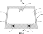
- the light-transmitting region R20 is a region of the laminated glass 10 through which visible light can pass. In order to ensure driving safety after the laminated glass 10 is mounted to a vehicle, a visible light transmittance of the light-transmitting region R20 is preferably greater than or equal to 70%.
- the light-blocking region R10 refers to a region of the laminated glass 10 where a visible light transmittance is relatively low. The light-blocking region R10 is disposed around a periphery of the laminated glass 10.
- the light-blocking region R10 has the first region R110 located blow the light-transmitting region R20.
- the first region R110 has one or more first function display regions R111 for displaying of the first image P1.
- the light-blocking region R10 further has a second region R120 and a third region R130.
- the second region R120 is located above the light-transmitting region R20.
- the third region R130 is located at a side of the light-transmitting region R20. Both the second region R120 and the third region R130 are configured for shielding electronic components or wiring.
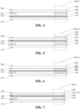
- the dielectric film 150 may be wrapped in the adhesive film 130 ( see FIG. 7 ).
- the dielectric film 150 is located in the first region R110.
- An orthographic projection of the dielectric film 150 on the second transparent substrate 120 covers all of the first function display regions R111.
- the dielectric film 150 can reflect S-polarized light.
- the dielectric film 150 can reflect S-polarized light.
- the dielectric film 150 may be disposed on the fourth surface 122 ( see FIG. 5 ).
- the dielectric film 150 may be disposed on the third surface 121 ( see FIG. 6 ).
- the dielectric film 150 may be wrapped in the adhesive film 130 ( see FIG. 7 ). A combination of the second transparent substrate 120 and the dielectric film 150 allows the second transparent substrate 120 to reflect S-polarized light.
- the dielectric film 150 can reflect P-polarized light.
- the dielectric film 150 may be, but is not limited to, a high refractive index layer, a low refractive index layer, a metal film (including one to five silver layers), or a laminated polyethylene terephthalate (PET).
- PET polyethylene terephthalate
- the dielectric film 150 may be disposed on the fourth surface 122 ( see FIG. 5 ).
- the dielectric film 150 may be disposed on the third surface 121 ( see FIG. 6 ).
- the dielectric film 150 may be wrapped in the adhesive film 130 ( see FIG. 7 ).
- a combination of the second transparent substrate 120 and the dielectric film 150 allows the second transparent substrate 120 to reflect P-polarized light.
- the flexible display screens 160 are disposed in the first function display regions R111. Each of the flexible display screens 160 corresponds to one of the first function display regions R111. Each of the flexible display screens 160 may be disposed between the masking layer 140 and the third surface 121. Alternatively, each of the flexible display screens 160 may be disposed on the fourth surface 122.
- the flexible display screen 160 may be, but not limited to, a mini light-emitting diode (LED) display screen, a micro LED display screen, or an organic light-emitting diode (OLED) display screen.
- the flexible display screen 160 can generate an image directly.
- a projection light ray for forming the second image P2 is incident on the projection display region of the second function display region R211 at an angle of 50° to 72°, and the projection display region of the second function display region R211 has a reflectivity, for the projection light ray for forming the second image P2, greater than or equal to 8%.
- FIG. 13 is an exploded cross-sectional structural view of the laminated glass taken along line I-I of FIG. 10 according to another embodiment of the disclosure
- FIG. 14 is an exploded cross-sectional structural view of the laminated glass taken along line I-I of FIG. 10 according to another embodiment of the disclosure
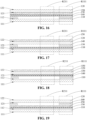
- FIG. 15 is an exploded cross-sectional structural view of the laminated glass taken along line I-I of FIG. 10 according to another embodiment of the disclosure
- FIG. 16 is an exploded cross-sectional structural view of the laminated glass taken along line I-I of FIG. 10 according to another embodiment of the disclosure.
- the laminated glass 10 further includes the dielectric film 150 disposed on the third surface 121 or the fourth surface 122.
- the dielectric film 150 can reflect P-polarized light or S-polarized light.
- the dielectric film 150 is disposed on the fourth surface 122, and the dielectric film 150 has anti-reflection capability for S-polarized light and a reflectivity for S-polarized light less than 6%.
- the dielectric film 150 is a laminated structure formed by a high refractive index layer and a low refractive index layer and disposed on the third surface 121 or the fourth surface 122, and can reflect P-polarized light or S-polarized light.
- the dielectric film 150 includes at least one metal layer (one to five silver layers) and is disposed on the second surface 112 or the third surface 121, and can reflect P-polarized light.
- the dielectric film 150 is a laminated PET and sandwiched between the second surface 112 and the third surface 121, and can reflect P-polarized light.
- the orthographic projection of the dielectric film 150 on the second transparent substrate 120 covers at least all of the second function display regions R211. In an embodiment, the orthographic projection of the dielectric film 150 on the second transparent substrate 120 cover all of the second function display regions R211. In another embodiment, the orthographic projection of the dielectric film 150 on the second transparent substrate 120 covers all of the second function display regions R211 and all of the first function display regions R111.
- the dielectric film 150 is disposed on the fourth surface 122.
- the dielectric film 150 can reflect P-polarized light and have a reflectivity for P-polarized light greater than 10%.
- the first surface 111 of the first transparent substrate 110 has a very low reflectivity for P-polarized light incident at an angle of 50° to 72°.
- the first surface 111 has a reflectivity for P-polarized light incident at an angle of 57° less than 1%, so that reflection of the first surface 111 for the light ray emitted can be weakened, that is, ghosting caused by reflection of the first surface 111 and reflection of the fourth surface 122, for the light ray emitted by the light source at one side of the fourth surface 122, can be further weakened.
- the dielectric film 150 can reflect S-polarized light and have a reflectivity for S-polarized light not less than 28%, thereby weakening reflection of the first surface 111 for the light ray emitted by the light source.
- image superposing between reflection of the first surface 111 and reflection of the fourth surface 122, for the light ray emitted by the light source at one side of the fourth surface 122 can be strengthened, that is, ghosting caused by reflection of the first surface 111 and reflection of the fourth surface 122, for the light ray emitted by the light source at one side of the fourth surface 122, can be weakened.
- the orthographic projection of the dielectric film 150 on the second transparent substrate 120 does not cover all of the first function display regions R111, the dielectric film 150 has anti-reflection capability for S-polarized light and a reflectivity for S-polarized light of not greater than 6%, so that reflection of the fourth surface 122 for the light ray emitted by the light source at one side of the fourth surface 122 can be weakened, thereby weakening ghosting caused by reflection of the first surface 111 and reflection of the fourth surface 122 for the light ray emitted by the light source at one side of the fourth surface 122.
- the dielectric film 150 is disposed between the masking layer 140 and the adhesive film 130.
- the orthographic projection of the dielectric film 150 on the second transparent substrate 120 covers all of the second function display regions R211.
- the dielectric film 150 can reflect P-polarized light and have a reflectivity for P-polarized light greater than 10%.
- Each of the first surface 111 of the first transparent substrate 110 and the fourth surface 122 of the second transparent substrate 120 has a very low reflectivity for P-polarized light incident at an angle of 50° to 72°.
- the dielectric film 150 is disposed between the adhesive film 130 and the third surface 121.
- the dielectric film 150 can reflect P-polarized light and have a reflectivity for P-polarized light greater than 10%, so that reflection of the first surface 111 for the light ray emitted can be weakened, that is, ghosting caused by reflection of the first surface 111 and reflection of the fourth surface 122, for the light ray emitted by the light source at one side of the fourth surface 122, can be weakened.
- the dielectric film 150 is disposed on the fourth surface 122.
- the dielectric film 150 can reflect P-polarized light and have a reflectivity for P-polarized light greater than 10%.
- the first surface 111 of the first transparent substrate 110 has a very low reflectivity for P-polarized light incident at an angle of 50° to 72°.
- the dielectric film 150 is disposed between the adhesive film 130 and the masking layer 140.
- the dielectric film 150 can reflect P-polarized light and have a reflectivity for P-polarized light greater than 10%.
- Each of the first surface 111 of the first transparent substrate 110 and the fourth surface 122 of the second transparent substrate 120 has a very low reflectivity for P-polarized light incident at an angle of 50° to 72°.
- each of the first surface 111 and the fourth surface 122 has a reflectivity for P-polarized light incident at an angle of 57° less than 1%, so that reflection of the first surface 111 for the light ray emitted and the reflection of the fourth surface 111 for the light ray emitted can be weakened, that is, ghosting caused by reflection of the first surface 111 and reflection of the fourth surface 122, for the light ray emitted by the light source at one side of the fourth surface 122, can be weakened.
- the dielectric film 150 is disposed between the adhesive film 130 and the third surface 121.
- the dielectric film 150 can reflect P-polarized light and have a reflectivity for P-polarized light greater than 10%.
- Each of the first surface 111 of the first transparent substrate 110 and the fourth surface 122 of the second transparent substrate 120 has a very low reflectivity for P-polarized light incident at an angle of 50° to 72°.
- the dielectric film 150 is disposed in the adhesive film 130, so that the dielectric film 150 can be wrapped in the adhesive film 130.
- the dielectric film 150 in the case where a proportion of P-polarized light in a light ray emitted by a light source at one side of the fourth surface 122 ranges from 60% to 100%, the dielectric film 150 can reflect P-polarized light and have a reflectivity for P-polarized light greater than 10%.
- Each of the first surface 111 of the first transparent substrate 110 and the fourth surface 122 of the second transparent substrate 120 has a very low reflectivity for P-polarized light incident at an angle of 50° to 72°.
- each of the first surface 111 and the fourth surface 122 has a reflectivity for P-polarized light incident at an angle of 57° less than 1%, so that reflection of the first surface 111 for the light ray emitted and the reflection of the fourth surface 111 for the light ray emitted can be weakened, that is, ghosting caused by reflection of the first surface 111 and reflection of the fourth surface 122, for the light ray emitted by the light source at one side of the fourth surface 122, can be weakened.
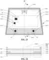
- FIG. 23 is a schematic structural view illustrating region division of the laminated glass 10 provided in another embodiment of the disclosure
- FIG. 24 is an exploded cross-sectional structural view of the laminated glass 10 taken along line I-I of FIG. 23 according to another embodiment of the disclosure.
- the laminated glass 10 further includes a colored region R30.
- the colored region R30 is located at one side of the light-blocking region R10 away from the light-transmitting region R20.
- the laminated glass 10 further includes a colored layer 180 carried on the second transparent substrate 120.
- the colored layer 180 is located in the colored region R30.
- the colored layer 180 is used for alignment and vehicle window fixing during mounting of the laminated glass 10, or disposed on a surface of an adhesive substrate of a fixing member.
- the colored layer 180 is disposed on an outermost surface of the laminated glass 10 and at one side of the fourth surface 122.
- An orthographic projection of the colored layer 180 on the second transparent substrate 120 covers the colored region R30.
- the colored region R30 can be configured to shield electronic components or wiring mounted later, and can also be configured to assist in mounting of the laminated glass 10 onto other devices.
- the colored region R30 facilitates gluing, aligning, or enhancement in adhesive strength.
- the upper boundary of the first region R110 is higher than an upper boundary of the colored region R30 in the first region R110.
- the upper boundary of the first region R110 is at least 80 mm higher than the upper boundary of the colored region R30 in the first region R110, so that sufficient space is reserved for the first function display region R111.
- FIG. 25 is a schematic structural view illustrating region division of the laminated glass provided in another embodiment of the disclosure.
- the laminated glass 10 further includes one or more first projection light sources 170 and one or more second projection light sources 190.
- the first projection light source 170 is configured to project the first image P1 to the first function display region R111.
- Each of the first projection light sources 170 corresponds to one of the first function display regions R111.
- the second projection light source 190 is configured to project the second image P2 to the second function display region R211.
- Each of the second projection light sources 190 corresponds to one of the second function display regions R211.
- the second projection light source 190 is configured to project an image to the second function display region R211, so that the second image P2 which has a larger size can be presented, thereby increasing the display diversity of the laminated glass 10.
- the second projection light source 190 is configured to project image onto the second function display region R211, so that the second image P2 which has a larger size can be presented, thereby increasing the display diversity of the laminated glass 10.
- a head-up display system is provided in the disclosure.
- the head-up display system includes the first projection light source 170 and the laminated glass 10 described in any one of embodiments where only the first function display region R111 is provided.
- the head-up system includes the first projection light source 170, the second projection light source 190, and the laminated glass 10 described in any one of embodiments where the second function display region R211 is provided.
- a proportion of P-polarized light in the projection light ray for forming the first image P1 ranges from 60% to 100%
- a proportion of S-polarized light in the projection light ray for forming the second image P2 ranges from 60% to 100%.
- a proportion of S-polarized light in the projection light ray for forming the first image P1 ranges from 60% to 100%
- a proportion of S-polarized light in the projection light ray for forming the second image P2 ranges from 60% to 100%.
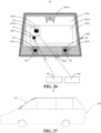
- FIG. 27 is a schematic view of a vehicle provided the disclosure.
- the vehicle 1 is further provided in the disclosure.
- the vehicle 1 includes the laminated glass 10 described in any one of the above embodiments.
- the vehicle 1 further includes a vehicle body 20.
- the laminated glass 10 is disposed on the vehicle body 20.
- the laminated glass 10 reference may be made to the foregoing illustrations, and details are not repeated herein.
- the first transparent substrate 110 is disposed on an outer side of the vehicle 1
- the second transparent substrate 120 is disposed on an inner side of the vehicle 1.
- Table 1 reflection data of the laminated glass without a transparent dielectric film for projection light rays in the first function display region of the light-blocking region Light Source Type Reflectivity Ordinary Light Source 7.5% P-polarized Light 0.3% S-polarized Light 13%
- Table 2 reflection data of the laminated glass with different transparent dielectric films for projection light rays in the first function display region Transparent dielectric film Type Light Source Type Reflectivity Anti-reflective film Ordinary Light Source 5.1% P-polarized Reflective film P-polarized Light 11% S-polarized Reflective film S-polarized Light 22%
- the projection display distance for the first image P1 ranges from 0.5 m to 5 m.
- the first image P1 may indicate key information such as vehicle speed, fuel level, or the engine speed.
- the projection display distance of the second image P2 is greater than or equal to 7.5 m.
- the second image P2 may be a relatively large image which can indicate information such as route navigation, a speeding reminder, or obstacle warnings.
Landscapes
- Physics & Mathematics (AREA)
- Engineering & Computer Science (AREA)
- Mechanical Engineering (AREA)
- General Physics & Mathematics (AREA)
- Optics & Photonics (AREA)
- Chemical & Material Sciences (AREA)
- Combustion & Propulsion (AREA)
- Transportation (AREA)
- Joining Of Glass To Other Materials (AREA)
- Laminated Bodies (AREA)
- Electroluminescent Light Sources (AREA)
Abstract
Description
-
- 1. This application claims priority to and the benefit of Patent Application No.
202111173404.7, filed October 08, 2021 - 2. This application claims priority to and the benefit of Patent Application No.
202111173403.2, filed October 08, 2021 - The disclosure relates to the field of automobiles, and in particular, to a laminated glass and a head-up display system.
- With the development of automotive intelligence, head-up display (HUD) systems are increasingly applied to automobiles to project images, such as real-time driving information, onto a front windshield. Due to the front windshield being laminated glass, a light ray emitted by a projection light source of the HUD system will undergo reflection when passing through each of two surfaces of the laminated glass in contact with air. The reflection on each of the two surfaces causes deviation, resulting in two mutually interfering ghost images, thus leading to a decrease in the quality of the image projected onto the front windshield.
- A laminated glass is provided in the disclosure. The laminated glass includes a first transparent substrate, a second transparent substrate, and an adhesive film. The first transparent substrate has a first surface and a second surface opposite the first surface. The second transparent substrate has a third surface and a fourth surface opposite the third surface. The third surface is closer to the second surface than the fourth surface. The laminated glass has a light-transmitting region and a light-blocking region surrounding at least part of a periphery of the light-transmitting region. The adhesive film is disposed between the second surface and the third surface and configured to adhere the first transparent substrate and the second transparent substrate. The light-transmitting region has a visible light transmittance greater than or equal to 70%. The light-blocking region has a visible light transmittance less than or equal to 5%. The light-blocking region has a first region located below the light-transmitting region, and the first region has one or more first function display regions for displaying of a first image.
- In some embodiments, the light-blocking region further has a second region located above the light-transmitting region and a third region disposed at a side of the light-transmitting region.
- In some embodiments, the first function display region includes at least one flexible display screen. The at least one flexible display screen is disposed between the second surface and the third surface and includes at least one of a mini light-emitting diode (LED) display screen, a micro LED display screen, or an organic light-emitting diode (OLED) display screen.
- In some embodiments, the first function display region has at least one projection display region. The at least one projection display region is configured to receive a projection light ray for forming the first image that is incident at an angle of 50° to 72°. The at least one projection display region has a reflectivity for the projection light ray incident greater than or equal to 4%.
- In some embodiments, the first function display region is the fourth surface, a proportion of S-polarized light in the projection light ray incident ranges from 60% to 100%. The at least one projection display region has the reflectivity for the projection light ray incident greater than or equal to 8%.
- In some embodiments, the first function display region is a dielectric film on the third surface or the fourth surface. A proportion of P-polarized light in the projection light ray incident ranges from 60% to 100%, and the at least one projection display region has the reflectivity for the projection light ray incident greater than or equal to 8%. Alternatively, a proportion of S-polarized light in the projection light ray incident ranges from 60% to 100%, and the at least one projection display region has the reflectivity for the projection light ray incident greater than or equal to 8%.
- In some embodiments, the first function display region is a metal film on the third surface. A proportion of P-polarized light in the projection light ray incident ranges from 60% to 100%. The at least one projection display region has the reflectivity for the projection light ray incident greater than or equal to 6%.
- In some embodiments, the first function display region is a laminated polyethylene terephthalate (PET), a proportion of P-polarized light in the projection light ray incident ranges from 60% to 100%. The at least one projection display region has the reflectivity for the projection light ray incident greater than or equal to 10%.
- In some embodiments, the light-blocking region includes a dark ink layer or a colored polymer film. The dark ink layer is disposed on at least one of the second surface or the third surface. The colored polymer film is disposed between the second surface and the third surface.
- In some embodiments, the flexible display screen or the display region is closer to the fourth surface than the dark ink layer or the colored polymer film.
- In some embodiments, the fourth surface has a colored region. An upper boundary of the first region is at least 80 mm higher than an upper boundary of the colored region located in the first region.
- In some embodiments, the light-transmitting region has one or more second function display regions. The one or more second function display regions have at least one projection display region for displaying of a second image.
- In some embodiments, the one or more first function display regions have at least one projection display region. A projection display distance for the first image ranges from 0.5 m to 5 m, and a projection display distance for the second image is greater than or equal to 7.5 m.
- In some embodiments, a projection light ray for forming the first image is incident on the at least one projection display region of the one or more first function display regions at an angle of 50° to 72°. The at least one projection display region of the one or more first function display regions has a reflectivity, for the projection light ray for forming the first image, greater than or equal to 4%. A projection light ray for forming the second image is incident on the at least one projection display region of the one or more second function display regions at an angle of 50° to 72°. The at least one projection display region of the one or more second function display regions has a reflectivity, for the projection light ray for forming the second image, greater than or equal to 8%.
- In some embodiments, the laminated glass further includes a dielectric film. The dielectric film is at least located in the one or more second function display regions.
- In some embodiments, the dielectric film is further located in the one or more first function display regions.
- In some embodiments, the adhesive film is of uniform thickness. A proportion of P-polarized light in the projection light ray for forming the second image ranges from 60% to 100%. The dielectric film is a laminated structure formed by a high refractive index layer and a low refractive index layer stacked with each other and includes at least one metal layer or laminated PET. The at least one projection display region of the one or more second function display regions has the reflectivity, for the projection light ray for forming the second image incident at an angle of 50° to 72°, greater than or equal to 10%.
- In some embodiments, the adhesive film is of uniform thickness or wedge-shaped. The dielectric film is disposed on the fourth surface and is an anti-reflective film. The second function display region is the first surface. A proportion of S-polarized light in the projection light ray for forming the second image ranges from 60% to 100%. The anti-reflective film has a reflectivity for the projection light ray for forming the second image less than or equal to 6%. The at least one projection display region of the one or more second function display regions has the reflectivity, for the projection light ray for forming the second image incident at an angle of 50° to 72°, greater than or equal to 8%.
- In some embodiments, the adhesive film is wedge-shaped, a proportion of S-polarized light in the projection light ray for forming the second image ranges from 60% to 100%. The dielectric film is a laminated structure disposed on the third surface or the fourth surface and formed by a high refractive index layer and a low refractive index layer stacked with each other. The at least one projection display region of the one or more second function display regions has the reflectivity, for the projection light ray for forming the second image incident at an angle of 50° to 72°, greater than or equal to 28%.
- In some embodiments, the adhesive film is wedge-shaped, the second function display region is the fourth surface, a proportion of S-polarized light in the projection light ray for forming the second image ranges from 60% to 100%. The at least one projection display region of the one or more second function display regions has the reflectivity, for the projection light ray for forming the second image incident at the angle of 50° to 72°, greater than or equal to 8%.
- In some embodiments, a proportion of S-polarized light in a projection light ray for forming the first image ranges from 60% to 100%, or a proportion of P-polarized light in the projection light ray for forming the first image ranges from 60% to 100%.
- In some embodiments, the light-transmitting region further has a primary viewing region. The one or more second function display regions are disposed within the primary viewing region, and a lower boundary of the primary viewing region is at least 25 mm higher than an upper boundary of the first region.
- A head-up display system is further provided in the disclosure. The head-up display system includes a first projection light source and the above-mentioned laminated glass. The first projection light source is configured to emit a projection light ray for forming the first image to the first function display region.
- In some embodiments, the light-transmitting region has one or more second function display regions. The head-up display system further includes a second projection light source. The second projection light source is configured to emit a projection light ray for forming a second image to the second function display region.
- In some embodiments, a proportion of P-polarized light in the projection light ray for forming the first image ranges from 60% to 100%, and a proportion of S-polarized light in the projection light ray for forming the second image ranges from 60% to 100%.
- In some embodiments, a proportion of S-polarized light in the projection light ray for forming the first image ranges from 60% to 100%, and a proportion of P-polarized light in the projection light ray for forming the second image ranges from 60% to 100%.
- In some embodiments, a proportion of P-polarized light in the projection light ray for forming the first image ranges from 60% to 100%, and a proportion of P-polarized light in the projection light ray for forming the second image ranges from 60% to 100%.
- In some embodiments, a proportion of S-polarized light in the projection light ray for forming the first image ranges from 60% to 100%, and a proportion of S-polarized light in the projection light ray for forming the second image ranges from 60% to 100%.
- The laminated glass provided in the embodiments of the disclosure has the light-blocking region, which can reduce or even block reflected light A, where light incident on the fourth surface can enter the laminated glass and then be reflected by the first transparent substrate to form the reflected light A, thereby weakening or even blocking ghosting caused by the reflected light A and the reflected light B, where light incident on the fourth surface can enter the laminated glass and then be reflected by the second transparent substrate to form the reflected light B. Additionally, the laminated glass provided in the embodiments of the disclosure can reduce or even block incident light C which is incident on the first surface to enter the laminated glass, thereby weakening or even blocking ghosting caused by the reflected light B and the incident light C. Therefore, it can be seen that the laminated glass provided in the embodiments of the disclosure can enhance the quality of images projected thereon.
-
-
FIG. 1 is a schematic structural view illustrating region division of a laminated glass provided in an embodiment of the disclosure. -
FIG. 2 is a cross-sectional view of the laminated glass taken along line I-I ofFIG. 1 according to an embodiment of the disclosure. -
FIG. 3 is an exploded cross-sectional structural view of the laminated glass taken along line I-I ofFIG. 1 according to an embodiment of the disclosure. -
FIG. 4 is an exploded cross-sectional structural view of the laminated glass taken along line I-I ofFIG. 1 according to another embodiment of the disclosure. -
FIG. 5 is an exploded cross-sectional structural view of the laminated glass taken along line I-I ofFIG. 1 according to another embodiment of the disclosure. -
FIG. 6 is an exploded cross-sectional structural view of the laminated glass taken along line I-I ofFIG. 1 according to another embodiment of the disclosure. -
FIG. 7 is an exploded cross-sectional structural view of the laminated glass taken along line I-I ofFIG. 1 according to another embodiment of the disclosure. -
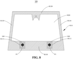
FIG. 8 is a schematic structural view illustrating region division of a laminated glass provided in another embodiment of the disclosure. -
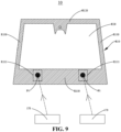
FIG. 9 is a schematic structural view illustrating region division of a laminated glass provided in another embodiment of the disclosure. -
FIG. 10 is a schematic structural view illustrating region division of a laminated glass provided in another embodiment of the disclosure. -
FIG. 11 is an exploded cross-sectional structural view of the laminated glass taken along line I-I ofFIG. 10 according to another embodiment of the disclosure. -
FIG. 12 is an exploded cross-sectional structural view of the laminated glass taken along line I-I ofFIG. 10 according to another embodiment of the disclosure. -
FIG. 13 is an exploded cross-sectional structural view of the laminated glass taken along line I-I ofFIG. 10 according to another embodiment of the disclosure. -
FIG. 14 is an exploded cross-sectional structural view of the laminated glass taken along line I-I ofFIG. 10 according to another embodiment of the disclosure. -
FIG. 15 is an exploded cross-sectional structural view of the laminated glass taken along line I-I ofFIG. 10 according to another embodiment of the disclosure. -
FIG. 16 is an exploded cross-sectional structural view of the laminated glass taken along line I-I ofFIG. 10 according to another embodiment of the disclosure. -
FIG. 17 is an exploded cross-sectional structural view of the laminated glass taken along line I-I ofFIG. 10 according to another embodiment of the disclosure. -
FIG. 18 is an exploded cross-sectional structural view of the laminated glass taken along line I-I ofFIG. 10 according to another embodiment of the disclosure. -
FIG. 19 is an exploded cross-sectional structural view of the laminated glass taken along line I-I ofFIG. 10 according to another embodiment of the disclosure. -
FIG. 20 is an exploded cross-sectional structural view of the laminated glass taken along line I-I ofFIG. 10 according to another embodiment of the disclosure. -
FIG. 21 is an exploded cross-sectional structural view of the laminated glass taken along line I-I ofFIG. 10 according to another embodiment of the disclosure. -
FIG. 22 is an exploded cross-sectional structural view of the laminated glass taken along line I-I ofFIG. 10 according to another embodiment of the disclosure. -
FIG. 23 is a schematic structural view illustrating region division of a laminated glass provided in another embodiment of the disclosure. -
FIG. 24 is an exploded cross-sectional structural view of the laminated glass taken along line I-I ofFIG. 23 according to another embodiment of the disclosure. -
FIG. 25 is a schematic structural view illustrating region division of a laminated glass provided in another embodiment of the disclosure. -
FIG. 26 is a schematic structural view illustrating region division of a laminated glass provided in another embodiment of the disclosure. -
FIG. 27 is a schematic view of a vehicle provided in the disclosure. - Reference numbers are described as follows:
laminated glass 10, firsttransparent substrate 110,first surface 111,second surface 112, secondtransparent substrate 120,third surface 121,fourth surface 122, light-blocking region R10, light-transmitting region R20,adhesive film 130, maskinglayer 140, first region R110, first function display region R111, first image P1, second region R120, third region R130,dielectric film 150,flexible display screen 160, firstprojection light source 170, primary viewing region R210, second function display region R211, second image P2, colored region R30, coloredlayer 180, secondprojection light source 190,vehicle 1,vehicle body 20. - The technical solutions in the embodiments of the disclosure are clearly and completely described in the following with reference to the accompanying drawings in the embodiments of the disclosure. Apparently, the described embodiments are merely a part of rather than all the embodiments of the disclosure. All other embodiments obtained by those of ordinary skill in the art based on the embodiments of the disclosure without creative efforts are within the scope of the disclosure.
- The term "embodiment" or "example" referred to herein means that a particular feature, structure, or feature described in connection with the embodiment or example may be contained in at least one embodiment of the disclosure. The phrase appearing in various places in the specification does not necessarily refer to the same embodiment, nor does it refer an independent or alternative embodiment that is mutually exclusive with other embodiments. It is expressly and implicitly understood by those skilled in the art that an embodiment described herein may be combined with other embodiments.
- Referring to
FIGS. 1 and2 ,FIG. 1 is a schematic structural view illustrating region division of a laminated glass provided in an embodiment of the disclosure, andFIG. 2 is a cross-sectional view of the laminated glass taken along line I-I odFIG. 1 according to an embodiment of the disclosure. Alaminated glass 10 is provided in the disclosure. Thelaminated glass 10 includes a firsttransparent substrate 110, a secondtransparent substrate 120, and anadhesive film 130. The firsttransparent substrate 110 has afirst surface 111 and asecond surface 112 opposite thefirst surface 111. The secondtransparent substrate 120 has athird surface 121 and afourth surface 122 opposite thethird surface 121. Thethird surface 121 is closer to thesecond surface 112 than thefourth surface 122. Thelaminated glass 10 has a light-transmitting region R20 and a light-blocking region R10 surrounding at least part of a periphery of the light-transmitting region R20. Theadhesive film 130 is disposed between thesecond surface 112 and thethird surface 121 and configured to adhere the firsttransparent substrate 110 and the secondtransparent substrate 120. The light-transmitting region R20 has a visible light transmittance greater than or equal to 70%. The light-blocking region R10 has a visible light transmittance less than or equal to 5%. The light-blocking region R10 has a first region R110 located below the light-transmitting region R20, and the first region R110 has one or more first function display regions R111 for displaying of a first image P1. - In an embodiment, the first
transparent substrate 110 is in close connection with the secondtransparent substrate 120 via theadhesive film 130. In order to conveniently and clearly illustrate a layered structure of thelaminated glass 10, in the disclosure, a cross-sectional view ofFIG. 1 taken along line I-I is rotated by 90 degrees counterclockwise, all the structures of thelaminated glass 10 are separated, and the thickness of all the structures is amplified. For the convenience of illustration, the resulting figured is referred to as an exploded cross-sectional structural view taken along line I-I ofFIG. 1 . For example, referring toFIG. 3, FIG. 3 is an exploded cross-sectional structural view taken along line I-I ofFIG. 1 according to an embodiment of the disclosure.FIG. 3 is obtained by rotatingFIG. 2 by 90 degrees counterclockwise, separating all structures of thelaminated glass 10, and amplifying the thickness of all structures. It can be understood that, the subsequent exploded cross-sectional structural views are also illustrated with reference to the processing manners ofFIGS. 2 and 3 , and will not be described in detail hereinafter. - Each of the first
transparent substrate 110 and the secondtransparent substrate 120 may be a curved plate with light-transmitting capabilities. For example, each of the firsttransparent substrate 110 and the secondtransparent substrate 120 may be made of inorganic glass or organic glass. The inorganic glass may be, for example, soda-lime-silica glass, aluminum silicate glass, lithium aluminum silicate glass, or borosilicate glass. The organic glass may be, for example, polycarbonate (PC) glass, polymethyl methacrylate (PMMA) glass, or the like. Each of the firsttransparent substrate 110 and the secondtransparent substrate 120 may be transparent, or may be colored and have light-transmitting capabilities. The material of the firsttransparent substrate 110 may be the same as or different from the material of the secondtransparent substrate 120. - The light-transmitting region R20 is a region of the
laminated glass 10 through which visible light can pass. In order to ensure driving safety after thelaminated glass 10 is mounted to a vehicle, a visible light transmittance of the light-transmitting region R20 is preferably greater than or equal to 70%. The light-blocking region R10 refers to a region of thelaminated glass 10 where a visible light transmittance is relatively low. The light-blocking region R10 is disposed around a periphery of thelaminated glass 10. - The
adhesive film 130 is disposed between the firsttransparent substrate 110 and the secondtransparent substrate 120 to adhere the firsttransparent substrate 110 and the secondtransparent substrate 120. Theadhesive film 130 may be implemented in two structures, which will be described in detail hereinafter. - The light-blocking region R10 includes a
masking layer 140. Themasking layer 140 may be a dark ink layer or a colored polymer film. The dark ink layer is disposed on at least one of thesecond surface 112 or thethird surface 121. The colored polymer film is disposed between thesecond surface 112 and thethird surface 121. Themasking layer 140 has a low transmittance for a projection light ray. Themasking layer 140 is carried on the firsttransparent substrate 110 or the secondtransparent substrate 120 and located in the light-blocking region R10. Themasking layer 140 may be formed in the light-blocking region R10 through processes such as printing ink. Optionally, themasking layer 140 has a transmittance for the projection light ray less than or equal to 5%, preferably less than or equal to 1%. Optionally, themasking layer 140 may also be made of a resin film with dark color and low light transmittance. Alternatively, themasking layer 140 may also be made of a resin film with light color and low light transmittance. The resin film may be, for example, a polyvinyl butyral (PVB) or polyethylene terephthalate (PET) which is mass colored. - In an embodiment, referring to
FIG. 3, FIG. 3 is an exploded cross-sectional structural view of thelaminated glass 10 taken along line I-I ofFIG. 1 according to one embodiment of the disclosure. Themasking layer 140 is disposed on thesecond surface 112. In another embodiment of the disclosure, referring toFIG. 4, FIG. 4 is an exploded cross-sectional structural view taken along line I-I ofFIG. 1 according to another embodiment of the disclosure. Themasking layer 140 is disposed on thethird surface 121. - Specifically, if the
laminated glass 10 does not include themasking layer 140, a projection light ray emitted by a projection device in the vehicle, for forming the first image P1 onto thelaminated glass 10, is incident on thefourth surface 122 to enter thelaminated glass 10, and then will be reflected by thefirst surface 111 of the firsttransparent substrate 110 to form reflected light A. Accordingly, the projection light ray incident onto thelaminated glass 10 will also be reflected by thefourth surface 122 of the secondtransparent substrate 120 to enter the human eye. For the convenience of illustration, the projection light ray reflected by thefourth surface 122 is referred to as reflected light B. The reflected light B forms a main image visible to the human eye. The reflected light A forms a secondary image visible to the human eye. There is a certain offset between the secondary image and the main image. That is, a phenomenon of ghosting occurs. In the embodiments of the disclosure, thelaminated glass 10 includes themasking layer 140, which can reduce or even block the reflected light A, thereby weakening or even blocking the ghosting caused by the reflected light A and the reflected light B. In addition, since themasking layer 140 has a low transmittance for the projection light ray, themasking layer 140 can serve as a display background for the main image, thereby improving the visibility of the main image and the contrast in brightness between the main image and the ambient, and significantly improving the display quality of the main image. - An application scenario of the
laminated glass 10 is introduced below. In the case where thelaminated glass 10 is applied to avehicle 1, thelaminated glass 10 is mounted to thevehicle 1 at a certain inclination angle to serve as a front windshield. The firsttransparent substrate 110 of thelaminated glass 10 is a substrate exposed to the outside of thevehicle 1. The secondtransparent substrate 120 is a substrate inside thevehicle 1. To illustrate the beneficial effects in the case where thelaminated glass 10 includes themasking layer 140, a case where thelaminated glass 10 does not include themasking layer 140 will be described first. The projection device in the vehicle may project the first image P1 onto thelaminated glass 10 to form the first image P1 on the secondtransparent substrate 120. Objects outside the vehicle can also be seen from the inside of the vehicle through thelaminated glass 10. The projection device in the vehicle can emit a light ray to project the first image P1 onto thelaminated glass 10, where the light ray is incident on thefourth surface 122 to enter thelaminated glass 10, where the light ray can be reflected by thefourth surface 122 to form the reflected light B and be reflected by thefirst surface 111 to form the reflected light A. The reflected light B and the reflected light A do not coincide to generate a reflection ghost. A light ray from an object outside the vehicle can be incident on thefirst surface 111, enter thelaminated glass 10, and then pass through thelaminated glass 10 to enter the vehicle to form incident light C. The incident light C may form transmission ghosting due to the inclined mounting and the parallel thickness of thelaminated glass 10. Thelaminated glass 10 in the embodiments of the disclosure includes themasking layer 140, which can reduce or even block the reflected light A and the incident light C, thereby weakening or even blocking the reflection ghosting and the transmission ghosting. - In conclusion, the
laminated glass 10 provided in the embodiments of the disclosure has themasking layer 140 located in the light-blocking region R10, which can reduce or even block the reflection ghosting and the transmission ghosting. It can be seen that thelaminated glass 10 provided in the embodiments of the disclosure can enhance the quality of the image projected thereon. - Referring to
FIG. 1 again, the light-blocking region R10 has the first region R110 located blow the light-transmitting region R20. The first region R110 has one or more first function display regions R111 for displaying of the first image P1. The light-blocking region R10 further has a second region R120 and a third region R130. The second region R120 is located above the light-transmitting region R20. The third region R130 is located at a side of the light-transmitting region R20. Both the second region R120 and the third region R130 are configured for shielding electronic components or wiring. - It may be noted that the light-blocking region R10 is disposed to surround the light-transmitting region R20. That is, the first region R110, the second region R120, and the third region R130 are located in the light-blocking region R10 and cooperatively surround the light-transmitting region R20.
- In the embodiments, the light-blocking region R10 is divided into three regions. The first region R110 has one or more first function display regions R111. In the case where the first region R110 has multiple first function display regions R111, the multiple first function display regions R111 may be arranged separately or formed integrally. Alternatively, some of the multiple first function display regions R111 are arranged separately and the rest of the multiple first function display regions R111 are formed integrally. Each of the first function display regions R111 is used for displaying of a corresponding one first image P1. Optionally, a ratio of a total area of the one or more first function display region R111 to the area of the first region R110 is greater than 10%, achieving better display effects of the first image P1. The second region R120 and the third region R130 on the one hand serve for shielding electronics or wiring mounted in later applications.
- Referring to
FIG. 4 again, in an embodiment, the first function display region R111 is thefourth surface 122, a proportion of S-polarized light in the projection light ray incident ranges from 60% to 100%, and the first function display region R111 has the reflectivity for the projection light ray incident greater than or equal to 8%. - In the embodiments, preferably, the proportion of S-polarized light in the projection light ray is 100%, so that the reflectivity of the first function display region R111 for the projection light ray incident can be further improved, thereby improving the clarity of the first image P1.
- Referring to
FIGS. 5, 6, and 7 together,FIG. 5 is an exploded cross-sectional structural view of thelaminated glass 10 taken along line I-I ofFIG. 1 according to another embodiment of the disclosure,FIG. 6 is an exploded cross-sectional structural view of thelaminated glass 10 taken along line I-I ofFIG. 1 according to another embodiment of the disclosure, andFIG. 7 is an exploded cross-sectional structural view of the laminated glass taken along line I-I ofFIG. 1 according to another embodiment of the disclosure. Theadhesive film 130 is of uniform thickness. Thelaminated glass 10 further includes adielectric film 150. Thedielectric film 150 may be disposed on the third surface 121 (seeFIG. 6 ). Alternatively, thedielectric film 150 may be disposed on the fourth surface 122 (seeFIG. 5 ). Alternatively, thedielectric film 150 may be wrapped in the adhesive film 130 (seeFIG. 7 ). Thedielectric film 150 is located in the first region R110. An orthographic projection of thedielectric film 150 on the secondtransparent substrate 120 covers all of the first function display regions R111. Thedielectric film 150 can reflect S-polarized light. - In the embodiments, the
dielectric film 150 can reflect S-polarized light. Thedielectric film 150 may be disposed on the fourth surface 122 (seeFIG. 5 ). Alternatively, thedielectric film 150 may be disposed on the third surface 121 (seeFIG. 6 ). Alternatively, thedielectric film 150 may be wrapped in the adhesive film 130 (seeFIG. 7 ). A combination of the secondtransparent substrate 120 and thedielectric film 150 allows the secondtransparent substrate 120 to reflect S-polarized light. For example, in the case where a proportion of S-polarized light in the projection light ray incident on one side of the secondtransparent substrate 120 is relatively large (for example, ranges from 60% to 100%), the secondtransparent substrate 120 has a relatively high reflectivity for the projection light ray incident on one side of the secondtransparent substrate 120 in the light-blocking region R10. For example, the secondtransparent substrate 120 has a reflectivity of 22% for the projection light ray incident at an angle of 60°in the light-blocking region R10. Preferably, a proportion of S-polarized light in the projection light ray is 100%, thereby further weakening or even eliminating light reflected by the firsttransparent substrate 110. The orthographic projection of thedielectric film 150 on the secondtransparent substrate 120 covers all of the first function display regions R111, thereby further improving the brightness and clarity of reflection of the secondtransparent substrate 120 for the light incident on one side of the secondtransparent substrate 120. - Referring to
FIGS. 5, 6, and 7, FIG. 5 is an exploded cross-sectional structural view of the laminated glass taken along line I-I ofFIG. 1 according to another embodiment of the disclosure,FIG. 6 is an exploded cross-sectional structural view of the laminated glass taken along line I-I ofFIG. 1 according to another embodiment of the disclosure, andFIG. 7 is an exploded cross-sectional structural view of the laminated glass taken along line I-I ofFIG. 1 according to another embodiment of the disclosure. Theadhesive film 130 is of uniform thickness. Thelaminated glass 10 further includes thedielectric film 150. Thedielectric film 150 may be disposed on the third surface 121 (seeFIG. 6 ). Alternatively, thedielectric film 150 may be disposed on the fourth surface 122 (seeFIG. 5 ). Alternatively, thedielectric film 150 may be wrapped in the adhesive film 130 (seeFIG. 7 ). Thedielectric film 150 is located in the first region R110. The orthographic projection of thedielectric film 150 on the secondtransparent substrate 120 covers all of the first function display regions R111. Thedielectric film 150 can reflect P-polarized light. - In the embodiments, the
dielectric film 150 can reflect P-polarized light. Thedielectric film 150 may be, but is not limited to, a high refractive index layer, a low refractive index layer, a metal film (including one to five silver layers), or a laminated polyethylene terephthalate (PET). Thedielectric film 150 may be disposed on the fourth surface 122 (seeFIG. 5 ). Alternatively, thedielectric film 150 may be disposed on the third surface 121 (seeFIG. 6 ). Alternatively, thedielectric film 150 may be wrapped in the adhesive film 130 (seeFIG. 7 ). A combination of the secondtransparent substrate 120 and thedielectric film 150 allows the secondtransparent substrate 120 to reflect P-polarized light. For example, in the case where a proportion of P-polarized light in the projection light ray incident on one side of the secondtransparent substrate 120 is relatively large (for example, ranges from 60% to 100%), the secondtransparent substrate 120 has a reflectivity for the P-polarized light in the projection light ray incident on one side of the secondtransparent substrate 120 in the light-blocking region R10. For example, the secondtransparent substrate 120 has a reflectivity of 20% for the projection light ray incident at an angle of 65°in the light-blocking region R10. Preferably, a proportion of P-polarized light in the projection light ray is 100%, thereby further weakening or even eliminating light reflected by the firsttransparent substrate 110, and improving the brightness and clarity of reflection of the secondtransparent substrate 120 for the light incident on one side of the secondtransparent substrate 120. It is also possible for the driver wearing sunglasses to view the first image P1 in the first function display region R111. - Referring to
FIGS. 8 and9 ,FIG. 8 is a schematic structural view illustrating region division of the laminated glass provided in another embodiment of the disclosure, andFIG. 9 is a schematic structural view illustrating region division of the laminated glass provided in another embodiment of the disclosure. Thelaminated glass 10 further includes one or more flexible display screens 160. Theflexible display screens 160 are located in the first region R110. Each of the one or moreflexible display screens 160 is disposed in a corresponding one of the first function display regions R111. Theflexible display screen 160 is configured to display the first image P1. Alternatively, thelaminated glass 10 further includes one or more firstprojection light sources 170. The firstprojection light source 170 is configured to project the first image P1 onto the first function display region R111. Each of the firstprojection light sources 170 is disposed corresponding to one of the first function display regions R111. - Referring to
FIG. 8 , in the embodiments, theflexible display screens 160 are disposed in the first function display regions R111. Each of theflexible display screens 160 corresponds to one of the first function display regions R111. Each of theflexible display screens 160 may be disposed between themasking layer 140 and thethird surface 121. Alternatively, each of theflexible display screens 160 may be disposed on thefourth surface 122. Theflexible display screen 160 may be, but not limited to, a mini light-emitting diode (LED) display screen, a micro LED display screen, or an organic light-emitting diode (OLED) display screen. Theflexible display screen 160 can generate an image directly. Light rays emitted by theflexible display screen 160, for forming the first image P1, can directly pass through the secondtransparent substrate 120 or do not need to pass through the secondtransparent substrate 120, without being affected by reflection of the firsttransparent substrate 110, thereby further avoiding ghosting caused by reflection of the firsttransparent substrate 110 for the light rays emitted and reflection of the secondtransparent substrate 120 for the light rays emitted. - In another embodiment, referring to
FIG. 9 , each firstprojection light source 170 is disposed corresponding to one first function display region R111. The firstprojection light source 170 is disposed at one side of the secondtransparent substrate 120. Optionally, a proportion of S-polarized light in light rays emitted by the firstprojection light source 170 ranges from 60% to 100%. With the aid of thedielectric film 150 that can reflect S-polarized light, the clarity of the first image P1 can be improved. Preferably, the proportion of S-polarized light in the light rays emitted by the firstprojection light source 170 is 100%, so that the clarity of the first image P1 can be further improved. - In yet another embodiment, in the case where the
laminated glass 10 has multiple first function display regions R111, theflexible display screens 160 are used in combination with the firstprojection light source 170. Some of theflexible display screens 160 are arranged corresponding to some of the first function display regions R111, and the rest of the firstprojection light sources 170 are arranged corresponding to the rest of the first function display regions R111. In the embodiments, it can not only weaken ghosting caused by reflection of the firsttransparent substrate 110 for the light rays emitted and reflection of the secondtransparent substrate 120 for the light rays emitted, but also increase the display diversity of the first function display regions R111. As such, mounting of thelaminated glass 10 can be optimized according to practical applications. - It may be noted that the
flexible display screen 160 or the first function display region R111 is closer to thefourth surface 122 than themasking layer 140, so that themasking layer 140 can serve as the display background of the first image P1. Themasking layer 140 may be, but not limited to, a dark ink layer or a colored polymer film. Here, a projection display distance for the first image P1 ranges from 0.5 m to 5 m. - Referring to
FIG. 10, FIG. 10 is a schematic structural view illustrating region division of the laminated glass provided in another embodiment of the disclosure. The light-transmitting region R20 further includes a primary viewing region R210. A lower boundary of the primary viewing region R210 is at least 25 mm higher than an upper boundary of the first region R110. - In the embodiments, the lower boundary of the primary viewing region R210 is at least 25 mm higher than the upper boundary of the first region R110, so that an optical sensitive zone can be avoided, and optical distortion between the first region R110 and the primary viewing region R210 can be avoided, where the optical distortion may interfere with an imaging in the first region R110 and an imaging in the primary viewing region R210.
- Referring to
FIG. 10 again, the primary viewing region R210 further has one or more second function display regions R211. The second function display region R211 is configured to display a second image P2. A projection display distance for the second image P2 is greater than or equal to 7.5 m. - In the embodiments, the
laminated glass 10 further has the second function display region R211. An area of the second function display region R211 is larger than that of the first function display region R111, so that thelaminated glass 10 can display the second image P2 larger than the first image P1, thereby enriching the image display of thelaminated glass 10. A projection light ray for forming the first image P1 is incident on the projection display region of the first function display region R111 at an angle of 50° to 72°, and the projection display region of the first function display region has a reflectivity, for the projection light ray for forming the first image P1, greater than or equal to 4%. A projection light ray for forming the second image P2 is incident on the projection display region of the second function display region R211 at an angle of 50° to 72°, and the projection display region of the second function display region R211 has a reflectivity, for the projection light ray for forming the second image P2, greater than or equal to 8%. - Referring to
FIGS. 11 and12 ,FIG. 11 is an exploded cross-sectional structural view of the laminated glass taken along line I-I ofFIG. 10 according to another embodiment of the disclosure, andFIG. 12 is an exploded cross-sectional structural view of the laminated glass taken along line I-I ofFIG. 10 according to another embodiment of the disclosure. A thickness of theadhesive film 130 gradually decreases in a direction from the second region R120 to the first region R110. An orthographic projection of theadhesive film 130 on the secondtransparent substrate 120 covers all of the second function display regions R211. - In the embodiments, the thickness of the
adhesive film 130 gradually decreases in the direction from the second region R120 to the first region R110. In other words, theadhesive film 130 is wedge-shaped. Optionally, a wedge-shaped angle caused by a gradual vary in thickness of theadhesive film 130 ranges from 0.15 mrad to 0.55 mrad. An orthographic projection of part of theadhesive film 130, which gradually varies in thickness, on the secondtransparent substrate 120 covers at least all of the second function display regions R211. The second function display region R211 is thefourth surface 122. A proportion of S-polarized light in the projection light ray incident for forming the second image P2 ranges from 60% to 100%. The second function display region R211 has a reflectivity greater than or equal to 8% for the projection light ray, for forming the second image P2, incident at an angle of 50° to 72°. Preferably, the proportion of S-polarized light in the projection light ray for forming the second image P2 is 100%. Theadhesive film 130 that gradually varies in thickness can correct, by means of a wedge-shaped angle, ghosting in the second function display region R211 caused by reflection of the firsttransparent substrate 110 for the projection light ray incident and refection of the secondtransparent substrate 120 for the projection light ray incident. In addition, in the case where thelaminated glass 10 has multiple second function display regions R211, wedge-shaped angles of theadhesive film 130 in different second function display regions R211 may be either equal or unequal. Since the second function display regions R211 differ in size, shape, and position, and incident angles of light sources are also different, different wedge-shaped angles are required to correct ghosting in each second function display region R211 caused by reflection of the firsttransparent substrate 110 for the projection light ray and reflection of the secondtransparent substrate 120 for the projection light ray. In the case where each of the second function display regions R211 has consistent setting conditions, the same wedge-shaped may also be used. - Referring to
FIG. 11 , in an embodiment, themasking layer 140 is disposed on thethird surface 121. Theadhesive film 130 is disposed between themasking layer 140 and thesecond surface 112. An orthographic projection of part of theadhesive film 130, which gradually varies in thickness, on the secondtransparent substrate 120 covers all of the second function display regions R211. Theadhesive film 130 may correct ghosting in the second function display region R211 caused by reflection of the firsttransparent substrate 110 for the projection light ray and reflection of the secondtransparent substrate 120 for the projection light ray, thereby improving the clarity of the second image P2. In another embodiment, referring toFIG. 12 , themasking layer 140 is disposed on thesecond surface 112. Theadhesive film 130 is disposed between themasking layer 140 and thethird surface 121. An orthographic projection of part of theadhesive film 130, which gradually varies in thickness, on the secondtransparent substrate 120 covers all of the second function display regions R211. Theadhesive film 130 may correct ghosting in the second function display region R211 caused by the reflection of the firsttransparent substrate 110 for the projection light ray and reflection of the secondtransparent substrate 120 for the projection light ray, thereby improving the clarity of the second image P2. Alternatively, an orthographic projection of part of theadhesive film 130, which gradually varies in thickness, on the secondtransparent substrate 120 covers all of the first function display regions R111 and all of the second function display regions R211. Theadhesive film 130 may correct ghosting in the first function display region R111, caused by reflection of the firsttransparent substrate 110 for the projection light ray and reflection of the secondtransparent substrate 120 for the projection light ray, and ghosting in the second function display region R211, caused by reflection of the firsttransparent substrate 110 for the projection light ray and reflection of the secondtransparent substrate 120 for the projection light ray, thereby not only improving the clarity of the second image P2, but also further improving the clarity of the first image P1. Further, the manufacturing efficiency of theadhesive film 130, the firsttransparent substrate 110, and the secondtransparent substrate 120 can be improved. - Referring to
FIGS. 13 to 16 ,FIG. 13 is an exploded cross-sectional structural view of the laminated glass taken along line I-I ofFIG. 10 according to another embodiment of the disclosure,FIG. 14 is an exploded cross-sectional structural view of the laminated glass taken along line I-I ofFIG. 10 according to another embodiment of the disclosure,FIG. 15 is an exploded cross-sectional structural view of the laminated glass taken along line I-I ofFIG. 10 according to another embodiment of the disclosure, andFIG. 16 is an exploded cross-sectional structural view of the laminated glass taken along line I-I ofFIG. 10 according to another embodiment of the disclosure. Thelaminated glass 10 further includes thedielectric film 150 disposed on thethird surface 121 or thefourth surface 122. Thedielectric film 150 can reflect P-polarized light or S-polarized light. Alternatively, thedielectric film 150 is disposed on thefourth surface 122, and thedielectric film 150 has anti-reflection capability for S-polarized light and a reflectivity for S-polarized light less than 6%. Alternatively, thedielectric film 150 is a laminated structure formed by a high refractive index layer and a low refractive index layer and disposed on thethird surface 121 or thefourth surface 122, and can reflect P-polarized light or S-polarized light. Alternatively, thedielectric film 150 includes at least one metal layer (one to five silver layers) and is disposed on thesecond surface 112 or thethird surface 121, and can reflect P-polarized light. Alternatively, thedielectric film 150 is a laminated PET and sandwiched between thesecond surface 112 and thethird surface 121, and can reflect P-polarized light. The orthographic projection of thedielectric film 150 on the secondtransparent substrate 120 covers at least all of the second function display regions R211. In an embodiment, the orthographic projection of thedielectric film 150 on the secondtransparent substrate 120 cover all of the second function display regions R211. In another embodiment, the orthographic projection of thedielectric film 150 on the secondtransparent substrate 120 covers all of the second function display regions R211 and all of the first function display regions R111. - Referring to
FIG. 13 , on the basis of the embodiment illustrated inFIG. 11 , thedielectric film 150 is disposed on thefourth surface 122. In an embodiment, in the case where a proportion of P-polarized light in a light ray emitted by a light source at one side of thefourth surface 122 ranges from 60% to 100%, thedielectric film 150 can reflect P-polarized light and have a reflectivity for P-polarized light greater than 10%. Thefirst surface 111 of the firsttransparent substrate 110 has a very low reflectivity for P-polarized light incident at an angle of 50° to 72°. For example, thefirst surface 111 has a reflectivity for P-polarized light incident at an angle of 57° less than 1%, so that reflection of thefirst surface 111 for the light ray emitted can be weakened, that is, ghosting caused by reflection of thefirst surface 111 and reflection of thefourth surface 122, for the light ray emitted by the light source at one side of thefourth surface 122, can be further weakened. In another embodiment, in the case where a proportion of S-polarized light in a light ray emitted by the light source at one side of thefourth surface 122 ranges from 60% to 100%, thedielectric film 150 can reflect S-polarized light and have a reflectivity for S-polarized light not less than 28%, thereby weakening reflection of thefirst surface 111 for the light ray emitted by the light source. In addition, with the aid of theadhesive film 130 that varies in thicknesses, image superposing between reflection of thefirst surface 111 and reflection of thefourth surface 122, for the light ray emitted by the light source at one side of thefourth surface 122, can be strengthened, that is, ghosting caused by reflection of thefirst surface 111 and reflection of thefourth surface 122, for the light ray emitted by the light source at one side of thefourth surface 122, can be weakened. In a further embodiment, in the case where a proportion of S-polarized light in the light ray emitted by the light source at one side of thefourth surface 122 ranges from 60% to 100%, the orthographic projection of thedielectric film 150 on the secondtransparent substrate 120 does not cover all of the first function display regions R111, thedielectric film 150 has anti-reflection capability for S-polarized light and a reflectivity for S-polarized light of not greater than 6%, so that reflection of thefourth surface 122 for the light ray emitted by the light source at one side of thefourth surface 122 can be weakened, thereby weakening ghosting caused by reflection of thefirst surface 111 and reflection of thefourth surface 122 for the light ray emitted by the light source at one side of thefourth surface 122. - Referring to
FIG. 14 , on the basis of the embodiment illustrated inFIG. 12 , thedielectric film 150 is disposed on thefourth surface 122. In an embodiment, in the case where a proportion of P-polarized light in a light ray emitted by a light source at one side of thefourth surface 122 ranges from 60% to 100%, thedielectric film 150 can reflect P-polarized light and have a reflectivity for P-polarized light greater than 10%. Thefirst surface 111 of the firsttransparent substrate 110 has a very low reflectivity for P-polarized light incident at an angle of 50° to 72°. For example, thefirst surface 111 has a reflectivity for P-polarized light incident at an angle of 57° less than 1%, so that reflection of thefirst surface 111 for the light ray emitted can be weakened, that is, ghosting caused by reflection of thefirst surface 111 and reflection of thefourth surface 122, for a light ray emitted by the light source at one side of thefourth surface 122, can be weakened. In another embodiment, in the case where a proportion of S-polarized light in a light ray emitted by the light source at one side of thefourth surface 122 ranges from 60% to 100%, thedielectric film 150 can reflect S-polarized light and have a reflectivity for S-polarized light not less than 28%, thereby weakening reflection of thefirst surface 111 for the light ray emitted by the light source. In addition, with the aid of theadhesive film 130 that varies in thicknesses, image superposing between reflection of thefirst surface 111 and reflection of thefourth surface 122, for the light ray emitted by the light source at one side of thefourth surface 122, can be strengthened, that is, ghosting caused by reflection of thefirst surface 111 and reflection of thefourth surface 122, for the light ray emitted by the light source at one side of thefourth surface 122, can be weakened. In a further embodiment, in the case where a proportion of S-polarized light in the light ray emitted by the light source at one side of thefourth surface 122 ranges from 60% to 100%, the orthographic projection of thedielectric film 150 on the secondtransparent substrate 120 does not cover all of the first function display regions R111, thedielectric film 150 has anti-reflection capability for S-polarized light and a reflectivity for S-polarized light of not greater than 6%, so that reflection of thefourth surface 122 for the light ray emitted by the light source at one side of thefourth surface 122 can be weakened, thereby weakening ghosting caused by reflection of thefirst surface 111 and reflection of thefourth surface 122 for the light ray emitted by the light source at one side of thefourth surface 122. - Referring to
FIG. 15 , on the basis of the embodiment illustrated inFIG. 11 , thedielectric film 150 is disposed between themasking layer 140 and theadhesive film 130. The orthographic projection of thedielectric film 150 on the secondtransparent substrate 120 covers all of the second function display regions R211. In an embodiment, in the case where a proportion of P-polarized light in a light ray emitted by a light source at one side of thefourth surface 122 ranges from 60% to 100%, thedielectric film 150 can reflect P-polarized light and have a reflectivity for P-polarized light greater than 10%. Each of thefirst surface 111 of the firsttransparent substrate 110 and thefourth surface 122 of the secondtransparent substrate 120 has a very low reflectivity for P-polarized light incident at an angle of 50° to 72°. For example, each of thefirst surface 111 and thefourth surface 122 has a reflectivity for P-polarized light incident at an angle of 57° less than 1%, so that reflection of thefirst surface 111 for the light ray emitted and the reflection of thefourth surface 111 for the light ray emitted can be weakened, that is, ghosting caused by thedielectric film 150 and reflection of thefirst surface 111 and reflection of thefourth surface 122, for the light ray emitted by the light source at one side of thefourth surface 122, can be weakened. - Referring to
FIG. 16 , on the basis of the embodiment illustrated inFIG. 12 , thedielectric film 150 is disposed between theadhesive film 130 and thethird surface 121. In an embodiment, in the case where a proportion of P-polarized light in a light ray emitted by a light source at one side of thefourth surface 122 ranges from 60% to 100%, thedielectric film 150 can reflect P-polarized light and have a reflectivity for P-polarized light greater than 10%, so that reflection of thefirst surface 111 for the light ray emitted can be weakened, that is, ghosting caused by reflection of thefirst surface 111 and reflection of thefourth surface 122, for the light ray emitted by the light source at one side of thefourth surface 122, can be weakened. - Referring to
FIGS. 17 to 22 ,FIG. 17 is an exploded cross-sectional structural view of the laminated glass taken along line I-I ofFIG. 10 according to another embodiment of the disclosure,FIG. 18 is an exploded cross-sectional structural view of the laminated glass taken along line I-I ofFIG. 10 according to another embodiment of the disclosure,FIG. 19 is an exploded cross-sectional structural view of the laminated glass taken along line I-I ofFIG. 10 according to another embodiment of the disclosure,FIG. 20 is an exploded cross-sectional structural view of the laminated glass taken along line I-I ofFIG. 10 according to another embodiment of the disclosure, andFIG. 21 is an exploded cross-sectional structural view of the laminated glass taken along line I-I ofFIG. 10 according to another embodiment of the disclosure. Theadhesive film 130 is of uniform thickness. Thelaminated glass 10 further includes thedielectric film 150. Thedielectric film 150 may be disposed on thethird surface 121. Alternatively, thedielectric film 150 may be disposed on thefourth surface 122. Alternatively, thedielectric film 150 may be wrapped in theadhesive film 130. Thedielectric film 150 can reflect P-polarized light. Alternatively, thedielectric film 150 can reflect polarized light and have a reflectivity for polarized light less than 6%. An orthographic projection of thedielectric film 150 on the secondtransparent substrate 120 covers at least all of the second function display regions R211. - Referring to
FIG. 17 , on the basis of the embodiment illustrated inFIG. 4 , thedielectric film 150 is disposed on thefourth surface 122. In an embodiment, in the case where a proportion of P-polarized light in a light ray emitted by a light source at one side of thefourth surface 122 ranges from 60% to 100%, thedielectric film 150 can reflect P-polarized light and have a reflectivity for P-polarized light greater than 10%. Thefirst surface 111 of the firsttransparent substrate 110 has a very low reflectivity for P-polarized light incident at an angle of 50° to 72°. For example, thefirst surface 111 has a reflectivity for P-polarized light incident at an angle of 57° less than 1%, so that reflection of thefirst surface 111 for the light ray emitted can be weakened, that is, ghosting caused by reflection of thefirst surface 111 and reflection of thefourth surface 122, for the light ray emitted by the light source at one side of thefourth surface 122, can be weakened. In another embodiment, in the case where a proportion of S-polarized light in the light ray emitted by the light source at one side of thefourth surface 122 ranges from 60% to 100%, the orthographic projection of thedielectric film 150 on the secondtransparent substrate 120 only covers all of the first function display regions R111, thedielectric film 150 has anti-reflection capability for S-polarized light and a reflectivity for S-polarized light of not greater than 6%, so that reflection of thefourth surface 122 for the light ray emitted by the light source at one side of thefourth surface 122 can be weakened, thereby weakening ghosting caused by reflection of thefirst surface 111 and reflection of thefourth surface 122 for the light ray emitted by the light source at one side of thefourth surface 122. - Referring to
FIG. 18 , on the basis of the embodiment illustrated inFIG. 3 , thedielectric film 150 is disposed on thefourth surface 122. In an embodiment, in the case where a proportion of P-polarized light in a light ray emitted by a light source at one side of thefourth surface 122 ranges from 60% to 100%, thedielectric film 150 can reflect P-polarized light and have a reflectivity for P-polarized light greater than 10%. Thefirst surface 111 of the firsttransparent substrate 110 has a very low reflectivity for P-polarized light incident at an angle of 50° to 72°. For example, thefirst surface 111 has a reflectivity for P-polarized light incident at an angle of 57° less than 1%, so that reflection of thefirst surface 111 for the light ray emitted can be weakened, that is, ghosting caused by reflection of thefirst surface 111 and reflection of thefourth surface 122, for a light ray emitted by the light source at one side of thefourth surface 122, can be weakened. In another embodiment, in the case where a proportion of S-polarized light in the light ray emitted by the light source at one side of thefourth surface 122 ranges from 60% to 100%, the orthographic projection of thedielectric film 150 on the secondtransparent substrate 120 does not cover all of the first function display regions R111, thedielectric film 150 has anti-reflection capability for S-polarized light and a reflectivity for S-polarized light of not greater than 6%, so that reflection of thefourth surface 122 for the light ray emitted by the light source at one side of thefourth surface 122 can be weakened, thereby weakening ghosting caused by reflection of thefirst surface 111 and reflection of thefourth surface 122 for the light ray emitted by the light source at one side of thefourth surface 122. - Referring to
FIG. 19 , on the basis of the embodiment illustrated inFIG. 4 , thedielectric film 150 is disposed between theadhesive film 130 and themasking layer 140. In an embodiment, in the case where a proportion of P-polarized light in a light ray emitted by a light source at one side of thefourth surface 122 ranges from 60% to 100%, thedielectric film 150 can reflect P-polarized light and have a reflectivity for P-polarized light greater than 10%. Each of thefirst surface 111 of the firsttransparent substrate 110 and thefourth surface 122 of the secondtransparent substrate 120 has a very low reflectivity for P-polarized light incident at an angle of 50° to 72°. For example, each of thefirst surface 111 and thefourth surface 122 has a reflectivity for P-polarized light incident at an angle of 57° less than 1%, so that reflection of thefirst surface 111 for the light ray emitted and the reflection of thefourth surface 111 for the light ray emitted can be weakened, that is, ghosting caused by reflection of thefirst surface 111 and reflection of thefourth surface 122, for the light ray emitted by the light source at one side of thefourth surface 122, can be weakened. - Referring to
FIG. 20 , on the basis of the embodiment illustrated inFIG. 3 , thedielectric film 150 is disposed between theadhesive film 130 and thethird surface 121. In an embodiment, in the case where a proportion of P-polarized light in a light ray emitted by a light source at one side of thefourth surface 122 ranges from 60% to 100%, thedielectric film 150 can reflect P-polarized light and have a reflectivity for P-polarized light greater than 10%. Each of thefirst surface 111 of the firsttransparent substrate 110 and thefourth surface 122 of the secondtransparent substrate 120 has a very low reflectivity for P-polarized light incident at an angle of 50° to 72°. For example, each of thefirst surface 111 and thefourth surface 122 has a reflectivity for P-polarized light incident at an angle of 57° less than 1%, so that reflection of thefirst surface 111 for the light ray emitted and the reflection of thefourth surface 111 for the light ray emitted can be weakened, that is, ghosting caused by reflection of thefirst surface 111 and reflection of thefourth surface 122, for the light ray emitted by the light source at one side of thefourth surface 122, can be weakened. - Referring to
FIG. 21 , on the basis of the embodiment illustrated inFIG. 4 , thedielectric film 150 is disposed in theadhesive film 130, so that thedielectric film 150 can be wrapped in theadhesive film 130. In an embodiment, in the case where a proportion of P-polarized light in a light ray emitted by a light source at one side of thefourth surface 122 ranges from 60% to 100%, thedielectric film 150 can reflect P-polarized light and have a reflectivity for P-polarized light greater than 10%. Each of thefirst surface 111 of the firsttransparent substrate 110 and thefourth surface 122 of the secondtransparent substrate 120 has a very low reflectivity for P-polarized light incident at an angle of 50° to 72°. For example, each of thefirst surface 111 and thefourth surface 122 has a reflectivity for P-polarized light incident at an angle of 57° less than 1%, so that reflection of thefirst surface 111 for the light ray emitted and the reflection of thefourth surface 111 for the light ray emitted can be weakened, that is, ghosting caused by reflection of thefirst surface 111 and reflection of thefourth surface 122, for the light ray emitted by the light source at one side of thefourth surface 122, can be weakened. - Referring to
FIG. 22 , on the basis of the embodiment illustrated inFIG. 3 , thedielectric film 150 is disposed in theadhesive film 130, so that thedielectric film 150 can be wrapped in theadhesive film 130. In an embodiment, in the case where a proportion of P-polarized light in a light ray emitted by a light source at one side of thefourth surface 122 ranges from 60% to 100%, thedielectric film 150 can reflect P-polarized light and have a reflectivity for P-polarized light greater than 10%. Each of thefirst surface 111 of the firsttransparent substrate 110 and thefourth surface 122 of the secondtransparent substrate 120 has a very low reflectivity for P-polarized light incident at an angle of 50° to 72°. For example, each of thefirst surface 111 and thefourth surface 122 has a reflectivity for P-polarized light incident at an angle of 57° less than 1%, so that reflection of thefirst surface 111 for the light ray emitted and the reflection of thefourth surface 111 for the light ray emitted can be weakened, that is, ghosting caused by reflection of thefirst surface 111 and reflection of thefourth surface 122, for the light ray emitted by the light source at one side of thefourth surface 122, can be weakened. - Referring to
FIGS. 23 and 24, FIG. 23 is a schematic structural view illustrating region division of thelaminated glass 10 provided in another embodiment of the disclosure, andFIG. 24 is an exploded cross-sectional structural view of thelaminated glass 10 taken along line I-I ofFIG. 23 according to another embodiment of the disclosure. Thelaminated glass 10 further includes a colored region R30. The colored region R30 is located at one side of the light-blocking region R10 away from the light-transmitting region R20. Thelaminated glass 10 further includes acolored layer 180 carried on the secondtransparent substrate 120. Thecolored layer 180 is located in the colored region R30. Thecolored layer 180 is used for alignment and vehicle window fixing during mounting of thelaminated glass 10, or disposed on a surface of an adhesive substrate of a fixing member. - In the embodiments, the
colored layer 180 is disposed on an outermost surface of thelaminated glass 10 and at one side of thefourth surface 122. An orthographic projection of thecolored layer 180 on the secondtransparent substrate 120 covers the colored region R30. The colored region R30 can be configured to shield electronic components or wiring mounted later, and can also be configured to assist in mounting of thelaminated glass 10 onto other devices. For example, the colored region R30 facilitates gluing, aligning, or enhancement in adhesive strength. Furthermore, the upper boundary of the first region R110 is higher than an upper boundary of the colored region R30 in the first region R110. Optionally, the upper boundary of the first region R110 is at least 80 mm higher than the upper boundary of the colored region R30 in the first region R110, so that sufficient space is reserved for the first function display region R111. - Referring to
FIG. 25, FIG. 25 is a schematic structural view illustrating region division of the laminated glass provided in another embodiment of the disclosure. Thelaminated glass 10 further includes one or more firstprojection light sources 170 and one or more second projectionlight sources 190. The firstprojection light source 170 is configured to project the first image P1 to the first function display region R111. Each of the firstprojection light sources 170 corresponds to one of the first function display regions R111. The secondprojection light source 190 is configured to project the second image P2 to the second function display region R211. Each of the second projectionlight sources 190 corresponds to one of the second function display regions R211. - In the embodiments, the second
projection light source 190 is configured to project an image to the second function display region R211, so that the second image P2 which has a larger size can be presented, thereby increasing the display diversity of thelaminated glass 10. - Referring to
FIG. 26, FIG. 26 is a schematic structural view illustrating region division of the laminated glass provided in another embodiment of the disclosure. Thelaminated glass 10 further includes one or moreflexible display screens 160 and one or more second projectionlight sources 190. Theflexible display screens 160 are arranged in the first region R110. Each of theflexible display screens 160 is disposed corresponding to one of the first function display regions R111. Theflexible display screen 160 is configured to display the first image P1. The secondprojection light source 190 is configured to project the second image P2 onto the second function display region R211. Each of the one or more second projectionlight sources 190 is disposed corresponding to one of the second function display regions R211. - In the embodiments, the second
projection light source 190 is configured to project image onto the second function display region R211, so that the second image P2 which has a larger size can be presented, thereby increasing the display diversity of thelaminated glass 10. - A head-up display system is provided in the disclosure. In an embodiment (as illustrated in
FIG. 9 ), the head-up display system includes the firstprojection light source 170 and thelaminated glass 10 described in any one of embodiments where only the first function display region R111 is provided. In another embodiment (as illustrated inFIG. 25 ), the head-up system includes the firstprojection light source 170, the secondprojection light source 190, and thelaminated glass 10 described in any one of embodiments where the second function display region R211 is provided. - In an embodiment, a proportion of P-polarized light in the projection light ray for forming the first image P1 ranges from 60% to 100%, and a proportion of S-polarized light in the projection light ray for forming the second image P2 ranges from 60% to 100%.
- In another embodiment, a proportion of S-polarized light in the projection light ray for forming the first image P1 ranges from 60% to 100%, and a proportion of P-polarized light in the projection light ray for forming the second image P2 ranges from 60% to 100%.
- In a further embodiment, a proportion of P-polarized light in the projection light ray for forming the first image P1 ranges from 60% to 100%, and a proportion of P-polarized light in the projection light ray for forming the second image P2 ranges from 60% to 100%.
- In a further embodiment, a proportion of S-polarized light in the projection light ray for forming the first image P1 ranges from 60% to 100%, and a proportion of S-polarized light in the projection light ray for forming the second image P2 ranges from 60% to 100%.
- It may be noted that, preferably, a proportion of S-polarized light in the projection light ray is 100%, or proportion of P-polarized light in the projection light ray is 100%, thereby achieving a better projection effect.
- Referring to
FIG. 27, FIG. 27 is a schematic view of a vehicle provided the disclosure. Thevehicle 1 is further provided in the disclosure. Thevehicle 1 includes thelaminated glass 10 described in any one of the above embodiments. Thevehicle 1 further includes avehicle body 20. Thelaminated glass 10 is disposed on thevehicle body 20. For thelaminated glass 10, reference may be made to the foregoing illustrations, and details are not repeated herein. In the case where thelaminated glass 10 is applied to thevehicle 1, the firsttransparent substrate 110 is disposed on an outer side of thevehicle 1, and the secondtransparent substrate 120 is disposed on an inner side of thevehicle 1. - In the embodiments, the
vehicle 1 may be, but is not limited to, cars, multi-purpose automobiles (MPV), sports/suburban utility vehicles (SUV), off-road automobiles (ORV), pick-and-place automobiles, passenger cars, cargo cars, and the like. An included angle between thelaminated glass 10 and the vertical plane is referred to as a mounting angle, and typically ranges from 50° to 72°. In the case where nomasking layer 140 is provided in thelaminated glass 10, two instances of ghosting occur. On the one hand, projection light rays emitted from the interior of thevehicle 1 will be reflected by the firsttransparent substrate 110 and the secondtransparent substrate 120 to cause ghosting. On the other hand, ghosting may further be caused by light rays passing through thelaminated glass 1 from objects outside thevehicle 1, and reflected light formed by refection of thelaminated glass 10 for the projection light rays emitted from the interior of thevehicle 1. With the aid of themasking layer 140, the above ghosting can be weakened or even eliminated. With the aid of thedielectric film 150, the above ghosting can be further weakened or even eliminated, and ghosting in the second function region R211 can be weakened or even eliminated. In the case where the mounting angle is 60°, experiments are conducted on reflection of thedielectric film 150, with light-transmitting capabilities, for projection light rays in the first function display region R111. The obtained data is presented in the following two tables.Table 1: reflection data of the laminated glass without a transparent dielectric film for projection light rays in the first function display region of the light-blocking region Light Source Type Reflectivity Ordinary Light Source 7.5% P-polarized Light 0.3% S-polarized Light 13% Table 2: reflection data of the laminated glass with different transparent dielectric films for projection light rays in the first function display region Transparent dielectric film Type Light Source Type Reflectivity Anti-reflective film Ordinary Light Source 5.1% P-polarized Reflective film P-polarized Light 11% S-polarized Reflective film S-polarized Light 22% - In Table 1, in the case where the light source type is an ordinary light source, light emitted by the ordinary light source is an irregular collection of countless polarized lights, so when directly observed, it is impossible to determine which direction the light intensity is biased towards. This type of light, where the intensity of the light waves vibrating in various directions is equal, is also known as natural light. In the case where the light source type is P-polarized light, a proportion of P-polarized light in light rays emitted by the light source ranges from 60% to 100%. In the case where the light source type is S-polarized light, a proportion of S-polarized light in light rays emitted by the light source ranges from 60% to 100%. The light source type in Table 2 can refer to the illustration of the light source type in Table 1, and will not be repeated herein. The anti-reflective film is the afore-mentioned
dielectric film 150 which has anti-reflection capability for S-polarized light and a relatively low reflectivity for S-polarized light (of not greater than 6%). The P-polarized reflective film is the afore-mentioneddielectric film 150 which can reflect P-polarized light. The S-polarized reflective film is the afore-mentioneddielectric film 150 which can reflect S-polarized light. The following can be seen from the experimental data in the above two tables. In an embodiment, in the first function display region R111, in the case where the firstprojection light source 170 is the ordinary light source and the anti-reflective film is mounted, a reflectivity of thefourth surface 122 for projection light rays emitted by the firstprojection light source 170 in the first function display region R111 decreases from 7.5% to 5.1%. In another embodiment, in the first function display region R111, in the case where the firstprojection light source 170 is configured to emit P-polarized light and the P-polarized reflective film is mounted, a reflectivity of thefourth surface 122 for projection light rays emitted by the firstprojection light source 170 in the first function display region R111 increases from 0.3% to 11%. In still another embodiment, in the first function display region R111, in the case where the firstprojection light source 170 is configured to emit S-polarized light and the S-polarized reflective film is mounted, the reflectivity of thefourth surface 122 for projection light rays emitted by the firstprojection light source 170 in the first function display region R111 increases from 13% to 22%. - Alternatively, the
laminated glass 10 further has a transparent conductive layer. The transparent conductive layer is mounted between the firsttransparent substrate 110 and the secondtransparent substrate 120. The transparent conductive layer has at least one of heat insulation capacity and heating function for reflecting infrared rays, and the transparent conductive layer covers at least 80% of the light-transmitting region R20. - Optionally, the projection display distance for the first image P1 ranges from 0.5 m to 5 m. The first image P1 may indicate key information such as vehicle speed, fuel level, or the engine speed. Alternatively, the projection display distance of the second image P2 is greater than or equal to 7.5 m. The second image P2 may be a relatively large image which can indicate information such as route navigation, a speeding reminder, or obstacle warnings.
- Although the embodiments of the disclosure have been illustrated and described above, it can be understood that the above embodiments are exemplary and cannot be understood as limitations on the disclosure. Those skilled in the art can make changes, modifications, replacements, and variations for the above embodiments within the scope of the disclosure, and these improvements and modifications are also considered to fall into the protection scope of the disclosure.
Claims (28)
- A laminated glass, comprising:a first transparent substrate having a first surface and a second surface opposite the first surface;a second transparent substrate having a third surface and a fourth surface opposite the third surface, wherein the third surface is closer to the second surface than the fourth surface; andwherein the laminated glass has a light-transmitting region and a light-blocking region surrounding at least part of a periphery of the light-transmitting region; andan adhesive film disposed between the second surface and the third surface and configured to adhere the first transparent substrate and the second transparent substrate;wherein the light-transmitting region has a visible light transmittance greater than or equal to 70%, the light-blocking region has a visible light transmittance less than or equal to 5%, the light-blocking region has a first region located below the light-transmitting region, and the first region has one or more first function display regions for displaying of a first image.
- The laminated glass of claim 1, wherein the light-blocking region further has:a second region located above the light-transmitting region; anda third region disposed at a side of the light-transmitting region.
- The laminated glass of claim 1, wherein the first function display region comprises at least one flexible display screen, and the at least one flexible display screen is disposed between the second surface and the third surface and comprises at least one of a mini light-emitting diode (LED) display screen, a micro LED display screen, or an organic light-emitting diode (OLED) display screen.
- The laminated glass of claim 1, wherein the first function display region has at least one projection display region, the at least one projection display region is configured to receive a projection light ray for forming the first image that is incident at an angle of 50° to 72°; and the at least one projection display region has a reflectivity for the projection light ray incident greater than or equal to 4%.
- The laminated glass of claim 4, wherein the first function display region is the fourth surface, a proportion of S-polarized light in the projection light ray incident ranges from 60% to 100%, and the at least one projection display region has the reflectivity for the projection light ray incident greater than or equal to 8%.
- The laminated glass of claim 4, wherein the first function display region is a dielectric film on the third surface or the fourth surface, whereina proportion of P-polarized light in the projection light ray incident ranges from 60% to 100%, and the at least one projection display region has the reflectivity for the projection light ray incident greater than or equal to 8%; ora proportion of S-polarized light in the projection light ray incident ranges from 60% to 100%, and the at least one projection display region has the reflectivity for the projection light ray incident greater than or equal to 8%.
- The laminated glass of claim 4, wherein the first function display region is a metal film on the third surface, a proportion of P-polarized light in the projection light ray incident ranges from 60% to 100%, and the at least one projection display region has the reflectivity for the projection light ray incident greater than or equal to 6%.
- The laminated glass of claim 4, wherein the first function display region is a laminated polyethylene terephthalate (PET), a proportion of P-polarized light in the projection light ray incident ranges from 60% to 100%, and the at least one projection display region has the reflectivity for the projection light ray incident greater than or equal to 10%.
- The laminated glass of claim 3 or 4, wherein the light-blocking region comprises a dark ink layer or a colored polymer film, the dark ink layer is disposed on at least one of the second surface or the third surface, and the colored polymer film is disposed between the second surface and the third surface.
- The laminated glass of claim 9, wherein the flexible display screen or the display region is closer to the fourth surface than the dark ink layer or the colored polymer film.
- The laminated glass of claim 1, wherein the fourth surface has a colored region, an upper boundary of the first region is at least 80 mm higher than an upper boundary of the colored region located in the first region.
- The laminated glass of any one of claims 1 to 11, wherein the light-transmitting region has one or more second function display regions, and the one or more second function display regions have at least one projection display region for displaying of a second image.
- The laminated glass of claim 12, wherein the one or more first function display regions have at least one projection display region, a projection display distance for the first image ranges from 0.5 m to 5 m, and a projection display distance for the second image is greater than or equal to 7.5 m.
- The laminated glass of claim 13, wherein a projection light ray for forming the first image is incident on the at least one projection display region of the one or more first function display regions at an angle of 50° to 72°, and the at least one projection display region of the one or more first function display regions has a reflectivity, for the projection light ray for forming the first image, greater than or equal to 4%; and a projection light ray for forming the second image is incident on the at least one projection display region of the one or more second function display regions at an angle of 50° to 72°, and the at least one projection display region of the one or more second function display regions has a reflectivity, for the projection light ray for forming the second image, greater than or equal to 8%.
- The laminated glass of claim 12 or 13, further comprising a dielectric film, wherein the dielectric film is at least located in the one or more second function display regions.
- The laminated glass of claim 15, wherein the dielectric film is further located in the one or more first function display regions.
- The laminated glass of claim 15, wherein the adhesive film is of uniform thickness, a proportion of P-polarized light in the projection light ray for forming the second image ranges from 60% to 100%, the dielectric film is a laminated structure formed by a high refractive index layer and a low refractive index layer stacked with each other and comprises at least one metal layer or laminated PET, and the at least one projection display region of the one or more second function display regions has the reflectivity, for the projection light ray for forming the second image incident at an angle of 50° to 72°, greater than or equal to 10%.
- The laminated glass of claim 15, wherein the adhesive film is of uniform thickness or wedge-shaped, the dielectric film is disposed on the fourth surface and is an anti-reflective film, and the second function display region is the first surface; a proportion of S-polarized light in the projection light ray for forming the second image ranges from 60% to 100%, and the anti-reflective film has a reflectivity for the projection light ray for forming the second image less than or equal to 6%; and the at least one projection display region of the one or more second function display regions has the reflectivity, for the projection light ray for forming the second image incident at an angle of 50° to 72°, greater than or equal to 8%.
- The laminated glass of claim 15, wherein the adhesive film is wedge-shaped, a proportion of S-polarized light in the projection light ray for forming the second image ranges from 60% to 100%; the dielectric film is a laminated structure disposed on the third surface or the fourth surface and formed by a high refractive index layer and a low refractive index layer stacked with each other; and the at least one projection display region of the one or more second function display regions has the reflectivity, for the projection light ray for forming the second image incident at an angle of 50° to 72°, greater than or equal to 28%.
- The laminated glass of claim 14, wherein the adhesive film is wedge-shaped, the second function display region is the fourth surface, a proportion of S-polarized light in the projection light ray for forming the second image ranges from 60% to 100%, and the at least one projection display region of the one or more second function display regions has the reflectivity, for the projection light ray for forming the second image incident at the angle of 50° to 72°, greater than or equal to 8%.
- The laminated glass of claim 13, wherein a proportion of S-polarized light in a projection light ray for forming the first image ranges from 60% to 100%, or a proportion of P-polarized light in the projection light ray for forming the first image ranges from 60% to 100%.
- The laminated glass of claim 12, wherein the light-transmitting region further has a primary viewing region, the one or more second function display regions are disposed within the primary viewing region, and a lower boundary of the primary viewing region is at least 25 mm higher than an upper boundary of the first region.
- A head-up display system, comprising a first projection light source and the laminated glass of any one of claims 1 to 22, wherein the first projection light source is configured to emit a projection light ray for forming the first image to the first function display region.
- The head-up display system of claim 23, wherein the light-transmitting region has one or more second function display regions, the head-up display system further comprises a second projection light source, and the second projection light source is configured to emit a projection light ray for forming a second image to the second function display region.
- The head-up display system of claim 24, wherein a proportion of P-polarized light in the projection light ray for forming the first image ranges from 60% to 100%, and a proportion of S-polarized light in the projection light ray for forming the second image ranges from 60% to 100%.
- The head-up display system of claim 24, wherein a proportion of S-polarized light in the projection light ray for forming the first image ranges from 60% to 100%, and a proportion of P-polarized light in the projection light ray for forming the second image ranges from 60% to 100%.
- The head-up display system of claim 24, wherein a proportion of P-polarized light in the projection light ray for forming the first image ranges from 60% to 100%, and a proportion of P-polarized light in the projection light ray for forming the second image ranges from 60% to 100%.
- The head-up display system of claim 24, wherein a proportion of S-polarized light in the projection light ray for forming the first image ranges from 60% to 100%, and a proportion of S-polarized light in the projection light ray for forming the second image ranges from 60% to 100%.
Applications Claiming Priority (3)
| Application Number | Priority Date | Filing Date | Title |
|---|---|---|---|
| CN202111173403.2A CN113858730B (en) | 2021-10-08 | 2021-10-08 | Laminated glass and head-up display system |
| CN202111173404.7A CN113878953A (en) | 2021-10-08 | 2021-10-08 | Laminated glass and head-up display system |
| PCT/CN2022/123855 WO2023056945A1 (en) | 2021-10-08 | 2022-10-08 | Laminated glass and head-up display system |
Publications (2)
| Publication Number | Publication Date |
|---|---|
| EP4397482A1 true EP4397482A1 (en) | 2024-07-10 |
| EP4397482A4 EP4397482A4 (en) | 2025-01-08 |
Family
ID=85803925
Family Applications (1)
| Application Number | Title | Priority Date | Filing Date |
|---|---|---|---|
| EP22877960.9A Pending EP4397482A4 (en) | 2021-10-08 | 2022-10-08 | LAMINATED GLASS AND HEAD-UP DISPLAY SYSTEM |
Country Status (6)
| Country | Link |
|---|---|
| US (3) | US12405465B2 (en) |
| EP (1) | EP4397482A4 (en) |
| JP (2) | JP7752761B2 (en) |
| KR (1) | KR20240066271A (en) |
| CN (3) | CN119017792B (en) |
| WO (1) | WO2023056945A1 (en) |
Cited By (2)
| Publication number | Priority date | Publication date | Assignee | Title |
|---|---|---|---|---|
| WO2023056945A1 (en) | 2021-10-08 | 2023-04-13 | 福耀玻璃工业集团股份有限公司 | Laminated glass and head-up display system |
| WO2023098690A1 (en) | 2021-11-30 | 2023-06-08 | 福耀玻璃工业集团股份有限公司 | Head-up display system |
Families Citing this family (2)
| Publication number | Priority date | Publication date | Assignee | Title |
|---|---|---|---|---|
| CN119065039B (en) * | 2024-08-26 | 2025-12-09 | 福耀玻璃工业集团股份有限公司 | Film-coated substrate and car window assembly |
| CN119141983B (en) * | 2024-10-11 | 2025-11-11 | 福耀玻璃工业集团股份有限公司 | Black display glass and black display system |
Family Cites Families (46)
| Publication number | Priority date | Publication date | Assignee | Title |
|---|---|---|---|---|
| JPH0891094A (en) * | 1994-09-26 | 1996-04-09 | Asahi Glass Co Ltd | Display system for vehicles |
| CN101038349A (en) | 2005-12-26 | 2007-09-19 | 旭硝子株式会社 | Laminated glass for vehicle |
| US7656585B1 (en) | 2008-08-19 | 2010-02-02 | Microvision, Inc. | Embedded relay lens for head-up displays or the like |
| CN102471153B (en) * | 2009-08-12 | 2014-09-17 | 旭硝子株式会社 | Laminated glass for use in vehicles |
| KR101869369B1 (en) * | 2014-10-10 | 2018-06-21 | 니폰 가야꾸 가부시끼가이샤 | Light reflecting film, and light controlling film, optical film, functional glass, and head-up display using light reflecting film |
| CN104267498B (en) * | 2014-10-14 | 2017-02-15 | 福耀玻璃工业集团股份有限公司 | Head up display system |
| CN104267499B (en) * | 2014-10-14 | 2016-08-17 | 福耀玻璃工业集团股份有限公司 | A kind of head-up-display system |
| JP2016153281A (en) | 2015-02-20 | 2016-08-25 | 富士フイルム株式会社 | Windshield glass and head-up display system |
| FR3045506B1 (en) * | 2015-12-16 | 2017-12-22 | Saint Gobain | LIGHT WINDSHIELD OF VEHICLE WITH INTERNAL LIGHT SIGNALING. |
| FR3046374B1 (en) | 2015-12-30 | 2018-01-19 | Saint-Gobain Glass France | GLAZING LIGHT OF VEHICLE WITH AMOLED SCREEN |
| CN108883982B (en) | 2016-04-07 | 2021-06-04 | Agc株式会社 | Laminated glass |
| CN106094072B (en) * | 2016-07-29 | 2019-04-12 | 福耀玻璃工业集团股份有限公司 | A kind of new line shows laminated glass and head-up-display system |
| CN106019424B (en) * | 2016-07-29 | 2017-11-03 | 福耀玻璃工业集团股份有限公司 | The new line that can adapt to high incidence angle shows laminated glass and its system |
| CN106094213A (en) * | 2016-08-25 | 2016-11-09 | 福耀玻璃工业集团股份有限公司 | A kind of can the head-up-display system that shows of multizone |
| CN108535867A (en) * | 2017-03-03 | 2018-09-14 | 怡利电子工业股份有限公司 | Full-time head-up display system |
| JP3210995U (en) | 2017-04-06 | 2017-06-15 | 怡利電子工業股▲ふん▼有限公司 | Full-time head-up display system |
| CA3060329C (en) | 2017-05-11 | 2021-09-14 | Saint-Gobain Glass France | Method for producing a thermoplastic combination film |
| EP3412448B1 (en) | 2017-06-02 | 2021-07-07 | AGC Inc. | Laminated glass |
| DE212018000265U1 (en) * | 2017-07-26 | 2020-02-28 | AGC Inc. | Vehicle laminated glass |
| PL3658371T3 (en) | 2017-07-27 | 2021-11-02 | Saint-Gobain Glass France | Thermoplastic film for laminated glass |
| CN109626848B (en) | 2017-10-05 | 2022-12-20 | Agc株式会社 | Laminated glass |
| JP7209461B2 (en) * | 2017-10-13 | 2023-01-20 | Agc株式会社 | Laminated glass for vehicles, image display systems and windshields |
| WO2019078123A1 (en) | 2017-10-20 | 2019-04-25 | Agc株式会社 | Laminated glass |
| CN110520295B (en) * | 2018-03-22 | 2022-12-30 | 法国圣戈班玻璃厂 | Composite glass pane for a head-up display with a conductive coating and an anti-reflection coating |
| JP7104788B2 (en) * | 2018-03-22 | 2022-07-21 | サン-ゴバン グラス フランス | Projection equipment for head-up display (HUD) with p-polarization component |
| EP3778517A4 (en) | 2018-03-29 | 2021-12-22 | Sekisui Chemical Co., Ltd. | INTERMEDIATE FILM FOR LAMINATED GLASS, LAMINATED GLASS AND HEAD-UP DISPLAY SYSTEM MANUFACTURING PROCESS |
| US10981358B2 (en) * | 2018-04-03 | 2021-04-20 | AGC Inc. | Laminated glass |
| MA52928A (en) | 2018-06-21 | 2021-04-28 | Saint Gobain | METHOD OF MANUFACTURING A COMPOSITE SCREEN HAVING A SELECTIVE POLARIZATION COATING |
| EP3885817A4 (en) * | 2018-11-20 | 2022-08-17 | Central Glass Company, Limited | HEAD-UP DISPLAY |
| EP3892598A4 (en) | 2018-12-05 | 2022-08-17 | Nippon Sheet Glass Company, Limited | LAMINATED GLASS FOR AUTOMOBILES |
| GB201904203D0 (en) * | 2019-03-26 | 2019-05-08 | Pikington Group Ltd | Laminated glazing and process |
| US12092818B2 (en) | 2019-07-05 | 2024-09-17 | Saint-Gobain Glass France | Projection assembly for a head-up display (HUD) with p-polarised radiation |
| JP7601011B2 (en) * | 2020-01-15 | 2024-12-17 | Agc株式会社 | Head-up display system |
| US12523870B2 (en) * | 2020-02-07 | 2026-01-13 | 3M Innovative Property Company | Optical systems for HUD systems |
| DE102020106160A1 (en) * | 2020-03-06 | 2021-09-09 | Bayerische Motoren Werke Aktiengesellschaft | Arrangement for the suppression of reflections in a windshield display system and windshield display system |
| CN112208310A (en) * | 2020-09-28 | 2021-01-12 | 福耀玻璃工业集团股份有限公司 | Laminated glass provided with camera |
| CN113238377B (en) * | 2021-04-14 | 2022-10-28 | 福耀玻璃工业集团股份有限公司 | Head-up display system |
| CN113238378B (en) * | 2021-04-14 | 2022-07-19 | 福耀玻璃工业集团股份有限公司 | Head-up display system |
| CN113071165B (en) * | 2021-04-16 | 2022-03-22 | 福耀玻璃工业集团股份有限公司 | Head-up display glass and head-up display system |
| WO2022244873A1 (en) | 2021-05-20 | 2022-11-24 | Agc株式会社 | Laminated glass, and head-up display system |
| WO2022266477A1 (en) * | 2021-06-17 | 2022-12-22 | Carlex Glass America, Llc | Glazing for head-up display |
| CN113960795B (en) * | 2021-09-18 | 2023-03-28 | 福耀玻璃工业集团股份有限公司 | Display window and vehicle |
| CN119017792B (en) | 2021-10-08 | 2025-10-17 | 福耀玻璃工业集团股份有限公司 | Laminated glass and head-up display system |
| CN113878953A (en) * | 2021-10-08 | 2022-01-04 | 福耀玻璃工业集团股份有限公司 | Laminated glass and head-up display system |
| CN116141775B (en) * | 2021-10-08 | 2026-01-02 | 福耀玻璃工业集团股份有限公司 | Laminated glass and head-up display system |
| CN117280266A (en) * | 2022-01-24 | 2023-12-22 | 法国圣戈班玻璃厂 | Projection device with two display areas on a composite glass pane |
-
2022
- 2022-10-08 CN CN202411152133.0A patent/CN119017792B/en active Active
- 2022-10-08 EP EP22877960.9A patent/EP4397482A4/en active Pending
- 2022-10-08 CN CN202411152130.7A patent/CN119017791B/en active Active
- 2022-10-08 CN CN202280067633.7A patent/CN118055856A/en active Pending
- 2022-10-08 WO PCT/CN2022/123855 patent/WO2023056945A1/en not_active Ceased
- 2022-10-08 JP JP2024521203A patent/JP7752761B2/en active Active
- 2022-10-08 KR KR1020247011888A patent/KR20240066271A/en active Pending
-
2024
- 2024-04-04 US US18/626,900 patent/US12405465B2/en active Active
- 2024-09-17 US US18/887,524 patent/US12379593B2/en active Active
-
2025
- 2025-07-08 US US19/262,924 patent/US20250334803A1/en active Pending
- 2025-09-30 JP JP2025164052A patent/JP2026001132A/en active Pending
Cited By (2)
| Publication number | Priority date | Publication date | Assignee | Title |
|---|---|---|---|---|
| WO2023056945A1 (en) | 2021-10-08 | 2023-04-13 | 福耀玻璃工业集团股份有限公司 | Laminated glass and head-up display system |
| WO2023098690A1 (en) | 2021-11-30 | 2023-06-08 | 福耀玻璃工业集团股份有限公司 | Head-up display system |
Also Published As
| Publication number | Publication date |
|---|---|
| US20250334803A1 (en) | 2025-10-30 |
| US20250013042A1 (en) | 2025-01-09 |
| US12379593B2 (en) | 2025-08-05 |
| CN119017791B (en) | 2025-10-17 |
| EP4397482A4 (en) | 2025-01-08 |
| WO2023056945A1 (en) | 2023-04-13 |
| JP2026001132A (en) | 2026-01-06 |
| KR20240066271A (en) | 2024-05-14 |
| US20240248304A1 (en) | 2024-07-25 |
| CN118055856A (en) | 2024-05-17 |
| JP7752761B2 (en) | 2025-10-10 |
| CN119017792A (en) | 2024-11-26 |
| US12405465B2 (en) | 2025-09-02 |
| CN119017792B (en) | 2025-10-17 |
| CN119017791A (en) | 2024-11-26 |
| JP2024535551A (en) | 2024-09-30 |
Similar Documents
| Publication | Publication Date | Title |
|---|---|---|
| US12379593B2 (en) | Laminated glass and head-up display system | |
| CN116141775B (en) | Laminated glass and head-up display system | |
| CA2025610C (en) | Ghost-free automotive head-up display employing a wedged windshield | |
| CN113878953A (en) | Laminated glass and head-up display system | |
| CN1732404A (en) | Head-up display with polarized light source and wide-angle P-polarized reflective polarizer | |
| CN106573527A (en) | Glass | |
| WO2023041060A1 (en) | Display vehicle window and vehicle | |
| EP4100274B1 (en) | Optical systems for hud systems | |
| EP4726459A1 (en) | Display window and vehicle | |
| CN114207506A (en) | Carrier composite glass element unit with projection area, carrier glass element and display system | |
| CN113966645B (en) | Vehicle composite glazing unit with projection area | |
| JP6659994B2 (en) | Display device | |
| US12368826B2 (en) | Head up display system and method | |
| JP2017090860A (en) | Display device | |
| EP4692015A1 (en) | Laminated glass and method for manufacturing same | |
| CN120840187A (en) | Laminated glass, head-up display system and vehicle | |
| CN116615687A (en) | Composite glass plate for projection device | |
| JPH06317702A (en) | Single-sided reflector for display assistance and liquid crystal display device | |
| CN120225382A (en) | Display system for a vehicle having two different modes of operation | |
| JP2017090623A (en) | Display device | |
| CN115343846A (en) | Imaging window manufacturing method, imaging window, imaging system and vehicle | |
| JP2019135533A (en) | Reflection screen and image display device |
Legal Events
| Date | Code | Title | Description |
|---|---|---|---|
| STAA | Information on the status of an ep patent application or granted ep patent |
Free format text: STATUS: THE INTERNATIONAL PUBLICATION HAS BEEN MADE |
|
| PUAI | Public reference made under article 153(3) epc to a published international application that has entered the european phase |
Free format text: ORIGINAL CODE: 0009012 |
|
| STAA | Information on the status of an ep patent application or granted ep patent |
Free format text: STATUS: REQUEST FOR EXAMINATION WAS MADE |
|
| 17P | Request for examination filed |
Effective date: 20240404 |
|
| AK | Designated contracting states |
Kind code of ref document: A1 Designated state(s): AL AT BE BG CH CY CZ DE DK EE ES FI FR GB GR HR HU IE IS IT LI LT LU LV MC ME MK MT NL NO PL PT RO RS SE SI SK SM TR |
|
| TPAC | Observations filed by third parties |
Free format text: ORIGINAL CODE: EPIDOSNTIPA |
|
| A4 | Supplementary search report drawn up and despatched |
Effective date: 20241209 |
|
| RIC1 | Information provided on ipc code assigned before grant |
Ipc: B60K 35/23 20240101ALI20241203BHEP Ipc: B32B 7/023 20190101ALI20241203BHEP Ipc: C03C 27/12 20060101ALI20241203BHEP Ipc: B60J 1/02 20060101ALI20241203BHEP Ipc: B60J 1/00 20060101ALI20241203BHEP Ipc: G02B 27/01 20060101ALI20241203BHEP Ipc: B32B 17/10 20060101AFI20241203BHEP |
|
| DAV | Request for validation of the european patent (deleted) | ||
| DAX | Request for extension of the european patent (deleted) | ||
| TPAC | Observations filed by third parties |
Free format text: ORIGINAL CODE: EPIDOSNTIPA |
|
| STAA | Information on the status of an ep patent application or granted ep patent |
Free format text: STATUS: EXAMINATION IS IN PROGRESS |
|
| 17Q | First examination report despatched |
Effective date: 20251104 |