EP4397475A1 - Composite compaction system supported by a number of morphable bag supports - Google Patents
Composite compaction system supported by a number of morphable bag supports Download PDFInfo
- Publication number
- EP4397475A1 EP4397475A1 EP23216020.0A EP23216020A EP4397475A1 EP 4397475 A1 EP4397475 A1 EP 4397475A1 EP 23216020 A EP23216020 A EP 23216020A EP 4397475 A1 EP4397475 A1 EP 4397475A1
- Authority
- EP
- European Patent Office
- Prior art keywords
- morphable
- bag
- support
- supports
- vacuum
- Prior art date
- Legal status (The legal status is an assumption and is not a legal conclusion. Google has not performed a legal analysis and makes no representation as to the accuracy of the status listed.)
- Granted
Links
Images






Classifications
-
- B—PERFORMING OPERATIONS; TRANSPORTING
- B29—WORKING OF PLASTICS; WORKING OF SUBSTANCES IN A PLASTIC STATE IN GENERAL
- B29C—SHAPING OR JOINING OF PLASTICS; SHAPING OF MATERIAL IN A PLASTIC STATE, NOT OTHERWISE PROVIDED FOR; AFTER-TREATMENT OF THE SHAPED PRODUCTS, e.g. REPAIRING
- B29C70/00—Shaping composites, i.e. plastics material comprising reinforcements, fillers or preformed parts, e.g. inserts
- B29C70/04—Shaping composites, i.e. plastics material comprising reinforcements, fillers or preformed parts, e.g. inserts comprising reinforcements only, e.g. self-reinforcing plastics
- B29C70/28—Shaping operations therefor
- B29C70/40—Shaping or impregnating by compression not applied
- B29C70/42—Shaping or impregnating by compression not applied for producing articles of definite length, i.e. discrete articles
- B29C70/44—Shaping or impregnating by compression not applied for producing articles of definite length, i.e. discrete articles using isostatic pressure, e.g. pressure difference-moulding, vacuum bag-moulding, autoclave-moulding or expanding rubber-moulding
- B29C70/443—Shaping or impregnating by compression not applied for producing articles of definite length, i.e. discrete articles using isostatic pressure, e.g. pressure difference-moulding, vacuum bag-moulding, autoclave-moulding or expanding rubber-moulding and impregnating by vacuum or injection
-
- B—PERFORMING OPERATIONS; TRANSPORTING
- B29—WORKING OF PLASTICS; WORKING OF SUBSTANCES IN A PLASTIC STATE IN GENERAL
- B29C—SHAPING OR JOINING OF PLASTICS; SHAPING OF MATERIAL IN A PLASTIC STATE, NOT OTHERWISE PROVIDED FOR; AFTER-TREATMENT OF THE SHAPED PRODUCTS, e.g. REPAIRING
- B29C70/00—Shaping composites, i.e. plastics material comprising reinforcements, fillers or preformed parts, e.g. inserts
- B29C70/04—Shaping composites, i.e. plastics material comprising reinforcements, fillers or preformed parts, e.g. inserts comprising reinforcements only, e.g. self-reinforcing plastics
- B29C70/28—Shaping operations therefor
- B29C70/40—Shaping or impregnating by compression not applied
- B29C70/42—Shaping or impregnating by compression not applied for producing articles of definite length, i.e. discrete articles
- B29C70/44—Shaping or impregnating by compression not applied for producing articles of definite length, i.e. discrete articles using isostatic pressure, e.g. pressure difference-moulding, vacuum bag-moulding, autoclave-moulding or expanding rubber-moulding
-
- B—PERFORMING OPERATIONS; TRANSPORTING
- B29—WORKING OF PLASTICS; WORKING OF SUBSTANCES IN A PLASTIC STATE IN GENERAL
- B29C—SHAPING OR JOINING OF PLASTICS; SHAPING OF MATERIAL IN A PLASTIC STATE, NOT OTHERWISE PROVIDED FOR; AFTER-TREATMENT OF THE SHAPED PRODUCTS, e.g. REPAIRING
- B29C31/00—Handling, e.g. feeding of the material to be shaped, storage of plastics material before moulding; Automation, i.e. automated handling lines in plastics processing plants, e.g. using manipulators or robots
- B29C31/04—Feeding of the material to be moulded, e.g. into a mould cavity
- B29C31/08—Feeding of the material to be moulded, e.g. into a mould cavity of preforms to be moulded, e.g. tablets, fibre reinforced preforms, extruded ribbons, tubes or profiles; Manipulating means specially adapted for feeding preforms, e.g. supports conveyors
-
- B—PERFORMING OPERATIONS; TRANSPORTING
- B29—WORKING OF PLASTICS; WORKING OF SUBSTANCES IN A PLASTIC STATE IN GENERAL
- B29C—SHAPING OR JOINING OF PLASTICS; SHAPING OF MATERIAL IN A PLASTIC STATE, NOT OTHERWISE PROVIDED FOR; AFTER-TREATMENT OF THE SHAPED PRODUCTS, e.g. REPAIRING
- B29C31/00—Handling, e.g. feeding of the material to be shaped, storage of plastics material before moulding; Automation, i.e. automated handling lines in plastics processing plants, e.g. using manipulators or robots
- B29C31/04—Feeding of the material to be moulded, e.g. into a mould cavity
- B29C31/08—Feeding of the material to be moulded, e.g. into a mould cavity of preforms to be moulded, e.g. tablets, fibre reinforced preforms, extruded ribbons, tubes or profiles; Manipulating means specially adapted for feeding preforms, e.g. supports conveyors
- B29C31/085—Feeding of the material to be moulded, e.g. into a mould cavity of preforms to be moulded, e.g. tablets, fibre reinforced preforms, extruded ribbons, tubes or profiles; Manipulating means specially adapted for feeding preforms, e.g. supports conveyors combined with positioning the preforms according to predetermined patterns, e.g. positioning extruded preforms on conveyors
-
- B—PERFORMING OPERATIONS; TRANSPORTING
- B29—WORKING OF PLASTICS; WORKING OF SUBSTANCES IN A PLASTIC STATE IN GENERAL
- B29C—SHAPING OR JOINING OF PLASTICS; SHAPING OF MATERIAL IN A PLASTIC STATE, NOT OTHERWISE PROVIDED FOR; AFTER-TREATMENT OF THE SHAPED PRODUCTS, e.g. REPAIRING
- B29C70/00—Shaping composites, i.e. plastics material comprising reinforcements, fillers or preformed parts, e.g. inserts
- B29C70/04—Shaping composites, i.e. plastics material comprising reinforcements, fillers or preformed parts, e.g. inserts comprising reinforcements only, e.g. self-reinforcing plastics
- B29C70/28—Shaping operations therefor
- B29C70/30—Shaping by lay-up, i.e. applying fibres, tape or broadsheet on a mould, former or core; Shaping by spray-up, i.e. spraying of fibres on a mould, former or core
- B29C70/34—Shaping by lay-up, i.e. applying fibres, tape or broadsheet on a mould, former or core; Shaping by spray-up, i.e. spraying of fibres on a mould, former or core and shaping or impregnating by compression, i.e. combined with compressing after the lay-up operation
- B29C70/342—Shaping by lay-up, i.e. applying fibres, tape or broadsheet on a mould, former or core; Shaping by spray-up, i.e. spraying of fibres on a mould, former or core and shaping or impregnating by compression, i.e. combined with compressing after the lay-up operation using isostatic pressure
-
- B—PERFORMING OPERATIONS; TRANSPORTING
- B29—WORKING OF PLASTICS; WORKING OF SUBSTANCES IN A PLASTIC STATE IN GENERAL
- B29C—SHAPING OR JOINING OF PLASTICS; SHAPING OF MATERIAL IN A PLASTIC STATE, NOT OTHERWISE PROVIDED FOR; AFTER-TREATMENT OF THE SHAPED PRODUCTS, e.g. REPAIRING
- B29C70/00—Shaping composites, i.e. plastics material comprising reinforcements, fillers or preformed parts, e.g. inserts
- B29C70/04—Shaping composites, i.e. plastics material comprising reinforcements, fillers or preformed parts, e.g. inserts comprising reinforcements only, e.g. self-reinforcing plastics
- B29C70/28—Shaping operations therefor
- B29C70/40—Shaping or impregnating by compression not applied
- B29C70/42—Shaping or impregnating by compression not applied for producing articles of definite length, i.e. discrete articles
- B29C70/44—Shaping or impregnating by compression not applied for producing articles of definite length, i.e. discrete articles using isostatic pressure, e.g. pressure difference-moulding, vacuum bag-moulding, autoclave-moulding or expanding rubber-moulding
- B29C70/446—Moulding structures having an axis of symmetry or at least one channel, e.g. tubular structures, frames
-
- B—PERFORMING OPERATIONS; TRANSPORTING
- B29—WORKING OF PLASTICS; WORKING OF SUBSTANCES IN A PLASTIC STATE IN GENERAL
- B29C—SHAPING OR JOINING OF PLASTICS; SHAPING OF MATERIAL IN A PLASTIC STATE, NOT OTHERWISE PROVIDED FOR; AFTER-TREATMENT OF THE SHAPED PRODUCTS, e.g. REPAIRING
- B29C70/00—Shaping composites, i.e. plastics material comprising reinforcements, fillers or preformed parts, e.g. inserts
- B29C70/04—Shaping composites, i.e. plastics material comprising reinforcements, fillers or preformed parts, e.g. inserts comprising reinforcements only, e.g. self-reinforcing plastics
- B29C70/28—Shaping operations therefor
- B29C70/54—Component parts, details or accessories; Auxiliary operations, e.g. feeding or storage of prepregs or SMC after impregnation or during ageing
-
- B—PERFORMING OPERATIONS; TRANSPORTING
- B29—WORKING OF PLASTICS; WORKING OF SUBSTANCES IN A PLASTIC STATE IN GENERAL
- B29C—SHAPING OR JOINING OF PLASTICS; SHAPING OF MATERIAL IN A PLASTIC STATE, NOT OTHERWISE PROVIDED FOR; AFTER-TREATMENT OF THE SHAPED PRODUCTS, e.g. REPAIRING
- B29C70/00—Shaping composites, i.e. plastics material comprising reinforcements, fillers or preformed parts, e.g. inserts
- B29C70/04—Shaping composites, i.e. plastics material comprising reinforcements, fillers or preformed parts, e.g. inserts comprising reinforcements only, e.g. self-reinforcing plastics
- B29C70/28—Shaping operations therefor
- B29C70/54—Component parts, details or accessories; Auxiliary operations, e.g. feeding or storage of prepregs or SMC after impregnation or during ageing
- B29C70/541—Positioning reinforcements in a mould, e.g. using clamping means for the reinforcement
-
- B—PERFORMING OPERATIONS; TRANSPORTING
- B29—WORKING OF PLASTICS; WORKING OF SUBSTANCES IN A PLASTIC STATE IN GENERAL
- B29C—SHAPING OR JOINING OF PLASTICS; SHAPING OF MATERIAL IN A PLASTIC STATE, NOT OTHERWISE PROVIDED FOR; AFTER-TREATMENT OF THE SHAPED PRODUCTS, e.g. REPAIRING
- B29C70/00—Shaping composites, i.e. plastics material comprising reinforcements, fillers or preformed parts, e.g. inserts
- B29C70/04—Shaping composites, i.e. plastics material comprising reinforcements, fillers or preformed parts, e.g. inserts comprising reinforcements only, e.g. self-reinforcing plastics
- B29C70/28—Shaping operations therefor
- B29C70/54—Component parts, details or accessories; Auxiliary operations, e.g. feeding or storage of prepregs or SMC after impregnation or during ageing
- B29C70/542—Placing or positioning the reinforcement in a covering or packaging element before or during moulding, e.g. drawing in a sleeve
-
- B—PERFORMING OPERATIONS; TRANSPORTING
- B29—WORKING OF PLASTICS; WORKING OF SUBSTANCES IN A PLASTIC STATE IN GENERAL
- B29C—SHAPING OR JOINING OF PLASTICS; SHAPING OF MATERIAL IN A PLASTIC STATE, NOT OTHERWISE PROVIDED FOR; AFTER-TREATMENT OF THE SHAPED PRODUCTS, e.g. REPAIRING
- B29C70/00—Shaping composites, i.e. plastics material comprising reinforcements, fillers or preformed parts, e.g. inserts
- B29C70/04—Shaping composites, i.e. plastics material comprising reinforcements, fillers or preformed parts, e.g. inserts comprising reinforcements only, e.g. self-reinforcing plastics
- B29C70/28—Shaping operations therefor
- B29C70/54—Component parts, details or accessories; Auxiliary operations, e.g. feeding or storage of prepregs or SMC after impregnation or during ageing
- B29C70/543—Fixing the position or configuration of fibrous reinforcements before or during moulding
-
- B—PERFORMING OPERATIONS; TRANSPORTING
- B29—WORKING OF PLASTICS; WORKING OF SUBSTANCES IN A PLASTIC STATE IN GENERAL
- B29C—SHAPING OR JOINING OF PLASTICS; SHAPING OF MATERIAL IN A PLASTIC STATE, NOT OTHERWISE PROVIDED FOR; AFTER-TREATMENT OF THE SHAPED PRODUCTS, e.g. REPAIRING
- B29C70/00—Shaping composites, i.e. plastics material comprising reinforcements, fillers or preformed parts, e.g. inserts
- B29C70/04—Shaping composites, i.e. plastics material comprising reinforcements, fillers or preformed parts, e.g. inserts comprising reinforcements only, e.g. self-reinforcing plastics
- B29C70/28—Shaping operations therefor
- B29C70/54—Component parts, details or accessories; Auxiliary operations, e.g. feeding or storage of prepregs or SMC after impregnation or during ageing
- B29C70/544—Details of vacuum bags, e.g. materials or shape
-
- B—PERFORMING OPERATIONS; TRANSPORTING
- B29—WORKING OF PLASTICS; WORKING OF SUBSTANCES IN A PLASTIC STATE IN GENERAL
- B29C—SHAPING OR JOINING OF PLASTICS; SHAPING OF MATERIAL IN A PLASTIC STATE, NOT OTHERWISE PROVIDED FOR; AFTER-TREATMENT OF THE SHAPED PRODUCTS, e.g. REPAIRING
- B29C70/00—Shaping composites, i.e. plastics material comprising reinforcements, fillers or preformed parts, e.g. inserts
- B29C70/04—Shaping composites, i.e. plastics material comprising reinforcements, fillers or preformed parts, e.g. inserts comprising reinforcements only, e.g. self-reinforcing plastics
- B29C70/28—Shaping operations therefor
- B29C70/54—Component parts, details or accessories; Auxiliary operations, e.g. feeding or storage of prepregs or SMC after impregnation or during ageing
- B29C70/56—Tensioning reinforcements before or during shaping
-
- B—PERFORMING OPERATIONS; TRANSPORTING
- B30—PRESSES
- B30B—PRESSES IN GENERAL
- B30B1/00—Presses, using a press ram, characterised by the features of the drive therefor, pressure being transmitted directly, or through simple thrust or tension members only, to the press ram or platen
- B30B1/003—Presses, using a press ram, characterised by the features of the drive therefor, pressure being transmitted directly, or through simple thrust or tension members only, to the press ram or platen by an elastic bag or diaphragm expanded by fluid pressure
-
- B—PERFORMING OPERATIONS; TRANSPORTING
- B29—WORKING OF PLASTICS; WORKING OF SUBSTANCES IN A PLASTIC STATE IN GENERAL
- B29L—INDEXING SCHEME ASSOCIATED WITH SUBCLASS B29C, RELATING TO PARTICULAR ARTICLES
- B29L2031/00—Other particular articles
- B29L2031/30—Vehicles, e.g. ships or aircraft, or body parts thereof
- B29L2031/3076—Aircrafts
- B29L2031/3082—Fuselages
Definitions
- the present disclosure relates generally to composite processing and more specifically to methods and apparatus for performing compaction on a composite material.
- Composite materials are strong, light-weight materials created by combining two or more functional components.
- a composite material may include reinforcing fibers bound in polymer resin matrix.
- the fibers can take the form of a unidirectional tape, woven cloth or fabric, or a braid.
- layers of composite material are typically laid up on a tool.
- the layers may be comprised of fibers in sheets.
- resin may be infused or pre-impregnated into the sheets. These types of sheets are commonly referred to as prepreg.
- An embodiment of the present disclosure provides a composite compaction system.
- the composite compaction system comprises a vacuum bag having a contact face configured to contact a composite material and a support face opposite the contact face, and a number of morphable bag supports formed of a flexible polymeric material connected to the support face and configured to morph between a retracted state and an engaged state.
- Each morphable bag support comprises fingers extending away from the support face and separated by gaps, and pressure chambers within the fingers connected by an internal channel.
- the illustrative examples recognize and take into account one or more different considerations.
- the illustrative examples recognize and take into account that existing automated solutions for composite compaction involve the use of linear actuators to support and manipulate compaction films from a single contact point.
- the illustrative examples recognize and take into account that the single contact point can provide an undesirably low amount of support of the film.
- the illustrative examples recognize and take into account that the rigidity of the mechanism can prevent the compaction film from adequate seating on contoured surfaces.
- Aircraft 100 has wing 102 and wing 104 attached to body 106. Aircraft 100 includes engine 108 attached to wing 102 and engine 110 attached to wing 104.
- Body 106 has tail section 112. Horizontal stabilizer 114, horizontal stabilizer 116, and vertical stabilizer 118 are attached to tail section 112 of body 106.
- Composite compaction system 200 in manufacturing environment 202 can be used to compact material 203 against support structure 206.
- material 203 takes the form of composite material 204.
- support structure 206 takes the form of a mandrel or other type of tool.
- support structure 206 takes the form of a substrate, such as a portion of a part.
- Composite compaction system 200 comprises vacuum bag 208 having contact face 210 and support face 212 opposite contact face 210.
- Contact face 210 is configured to contact material 203.
- contact face 210 is configured to contact composite material 204.
- Composite compaction system 200 also comprises number of morphable bag supports 214 connected to support face 212 and configured to morph between retracted state 218 and engaged state 220. In retracted state 218, number of morphable bag supports 214 can lift corners 222 of vacuum bag 208. In retracted state 218, number of morphable bag supports 214 hold a portion of vacuum bag 208 above support structure 206.
- number of morphable bag supports 214 is formed of flexible polymeric material 216.
- each of number of morphable bag supports 214 has a same design. In some illustrative examples, at least one of number of morphable bag supports 214 has a different design than another morphable bag support of number of morphable bag supports 214.
- Each morphable bag support of number of morphable bag supports 214 comprises fingers separated by gaps, the fingers extending outwardly away from the vacuum bag.
- first morphable bag support 224 comprises fingers 226 separated by gaps 228, fingers 226 extending outwardly away from vacuum bag 208.
- Second morphable bag support 230 comprises fingers 232 separated by gaps 234, fingers 232 extending outwardly away from vacuum bag 208.
- Each morphable bag support of number of morphable bag supports 214 further comprises pressure chambers within the fingers connected by an internal channel.
- first morphable bag support 224 comprises pressure chambers 236 within fingers 226 connected by internal channel 238.
- Second morphable bag support 230 comprises pressure chambers 240 within fingers 232 connected by internal channel 242.
- Second pressure source 252 is connected to pressure input 254 of second morphable bag support 230.
- second pressure source 252 can provide either vacuum 256 or positive pressure 258.
- the illustrative examples provide an apparatus that enables automated and controlled manipulation, support, and seating of compaction films used on composite fabrication processes.
- the illustrative examples utilize morphable bag supports.
- the morphable bag supports are attached to the compaction film along the periphery, providing adequate support and seating when conforming to the shape of the surface.
- morphable supports are attached to the compaction film along the entire periphery.
Landscapes
- Engineering & Computer Science (AREA)
- Mechanical Engineering (AREA)
- Chemical & Material Sciences (AREA)
- Composite Materials (AREA)
- Robotics (AREA)
- Textile Engineering (AREA)
- Physics & Mathematics (AREA)
- Fluid Mechanics (AREA)
- Casting Or Compression Moulding Of Plastics Or The Like (AREA)
- Moulding By Coating Moulds (AREA)
Abstract
Description
- The present disclosure relates generally to composite processing and more specifically to methods and apparatus for performing compaction on a composite material.
- Composite materials are strong, light-weight materials created by combining two or more functional components. For example, a composite material may include reinforcing fibers bound in polymer resin matrix. The fibers can take the form of a unidirectional tape, woven cloth or fabric, or a braid.
- In manufacturing composite structures, layers of composite material are typically laid up on a tool. The layers may be comprised of fibers in sheets. In some cases, resin may be infused or pre-impregnated into the sheets. These types of sheets are commonly referred to as prepreg.
- After laying up a layer of composite material on a tool, the composite material can be compacted onto the tool. Compaction can flatten and remove air and wrinkles from the composite material. It can be undesirably difficult to apply conventional composite compaction films over objects, especially those with a contour.
- Therefore, it would be desirable to have a method and apparatus that takes into account at least some of the issues discussed above, as well as other possible issues.
- An embodiment of the present disclosure provides a method of supporting a composite compaction system. A number of morphable bag supports of the composite compaction system is held in a retracted state. A contact face of a vacuum bag of the composite compaction system is placed in contact with a composite material on a support structure. The number of morphable bag supports is placed in an engaged state to conform to the support structure.
- An embodiment of the present disclosure provides a composite compaction system. The composite compaction system comprises a vacuum bag having a contact face configured to contact a composite material and a support face opposite the contact face, and a number of morphable bag supports formed of a flexible polymeric material connected to the support face and configured to morph between a retracted state and an engaged state.
- An embodiment of the present disclosure provides a composite compaction system. The composite compaction system comprises a vacuum bag having a contact face configured to contact a composite material and a support face opposite the contact face, and a number of morphable bag supports formed of a flexible polymeric material connected to the support face and configured to morph between a retracted state and an engaged state. Each morphable bag support comprises fingers extending away from the support face and separated by gaps, and pressure chambers within the fingers connected by an internal channel.
- The features and functions can be achieved independently in various embodiments of the present disclosure or may be combined in yet other embodiments in which further details can be seen with reference to the following description and drawings.
- The novel features believed characteristic of the illustrative embodiments are set forth in the appended claims. The illustrative embodiments, however, as well as a preferred mode of use, further objectives and features thereof, will best be understood by reference to the following detailed description of an illustrative embodiment of the present disclosure when read in conjunction with the accompanying drawings, wherein:
-
Figure 1 is an illustration of an aircraft in accordance with an illustrative embodiment; -
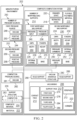
Figure 2 is an illustration of a block diagram of a manufacturing environment in accordance with an illustrative embodiment; -
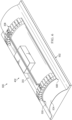
Figure 3 is an illustration of a composite compaction system with a number of morphable bag supports in a retracted state in accordance with an illustrative embodiment; -
Figure 4 is an illustration of a composite compaction system with a number of morphable bag supports in an engaged state in accordance with an illustrative embodiment; -
Figure 5 is an illustration of a composite compaction system with a number of morphable bag supports in a retracted state against an object in accordance with an illustrative embodiment; -
Figure 6 is an illustration of a composite compaction system with a number of morphable bag supports in an engaged state against an object in accordance with an illustrative embodiment; -
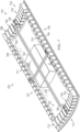
Figure 7 is an illustration of a composite compaction system with a number of morphable bag supports in a retracted state in accordance with an illustrative embodiment; -
Figure 8 is an illustration of a top view of a composite compaction system with a number of morphable bag supports in accordance with an illustrative embodiment; -
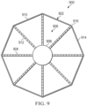
Figure 9 is an illustration of a top view of a composite compaction system with a number of morphable bag supports in accordance with an illustrative embodiment; -
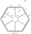
Figure 10 is an illustration of a top view of a composite compaction system with a number of morphable bag supports in accordance with an illustrative embodiment; -
Figure 11 is a flowchart of a method of supporting a composite compaction system in accordance with an illustrative embodiment; -
Figure 12 is an illustration of an aircraft manufacturing and service method in a form of a block diagram in accordance with an illustrative embodiment; and -
Figure 13 is an illustration of an aircraft in a form of a block diagram in which an illustrative embodiment may be implemented. - The illustrative examples recognize and take into account one or more different considerations. The illustrative examples recognize and take into account that existing automated solutions for composite compaction involve the use of linear actuators to support and manipulate compaction films from a single contact point. The illustrative examples recognize and take into account that the single contact point can provide an undesirably low amount of support of the film. The illustrative examples recognize and take into account that the rigidity of the mechanism can prevent the compaction film from adequate seating on contoured surfaces.
- The illustrative examples recognize and take into account that current compaction bag supports present some issues. The illustrative examples recognize and take into account that current compaction bag supports present insufficient support of compaction bag due to attachment points located only at corners. The illustrative examples recognize and take into account that current compaction bag supports provide a lack of conformity and adequate sealing of compaction bag to contoured surface due to current rigid supports. The illustrative examples also recognize and take into account that undesirably restraining the bag using the current compaction bag supports could undesirably impact the composite structure underneath.
- Turning now to
Figure 1 , an illustration of an aircraft is depicted in accordance with an illustrative embodiment.Aircraft 100 haswing 102 andwing 104 attached tobody 106.Aircraft 100 includesengine 108 attached towing 102 andengine 110 attached towing 104. -
Body 106 hastail section 112.Horizontal stabilizer 114,horizontal stabilizer 116, andvertical stabilizer 118 are attached totail section 112 ofbody 106. -
Aircraft 100 is an example of an aircraft having composite components that can be manufactured using composite compaction system of the illustrative examples. - Turning now to
Figure 2 , an illustration of a block diagram of a manufacturing environment is depicted in accordance with an illustrative embodiment.Composite compaction system 200 inmanufacturing environment 202 can be used tocompact material 203 againstsupport structure 206. In some illustrative examples,material 203 takes the form ofcomposite material 204. In some illustrative examples,support structure 206 takes the form of a mandrel or other type of tool. In some illustrative examples,support structure 206 takes the form of a substrate, such as a portion of a part. -
Composite compaction system 200 comprisesvacuum bag 208 havingcontact face 210 and supportface 212opposite contact face 210. Contactface 210 is configured to contactmaterial 203. In some illustrative examples,contact face 210 is configured to contactcomposite material 204.Composite compaction system 200 also comprises number of morphable bag supports 214 connected to supportface 212 and configured to morph between retractedstate 218 and engagedstate 220. In retractedstate 218, number of morphable bag supports 214 can liftcorners 222 ofvacuum bag 208. In retractedstate 218, number of morphable bag supports 214 hold a portion ofvacuum bag 208 abovesupport structure 206. In some illustrative examples, number of morphable bag supports 214 is formed of flexiblepolymeric material 216. - In some illustrative examples, each of number of morphable bag supports 214 has a same design. In some illustrative examples, at least one of number of morphable bag supports 214 has a different design than another morphable bag support of number of morphable bag supports 214.
- Each morphable bag support of number of morphable bag supports 214 comprises fingers separated by gaps, the fingers extending outwardly away from the vacuum bag. For example, first
morphable bag support 224 comprisesfingers 226 separated bygaps 228,fingers 226 extending outwardly away fromvacuum bag 208. Secondmorphable bag support 230 comprisesfingers 232 separated bygaps 234,fingers 232 extending outwardly away fromvacuum bag 208. - Each morphable bag support of number of morphable bag supports 214 further comprises pressure chambers within the fingers connected by an internal channel. For example, first
morphable bag support 224 comprisespressure chambers 236 withinfingers 226 connected byinternal channel 238. Secondmorphable bag support 230 comprisespressure chambers 240 withinfingers 232 connected byinternal channel 242. - Number of morphable bag supports 214 are actuated between
engaged state 220 and retractedstate 218 by modifying pressure within the pressure chambers of number of morphable bag supports 214. For example,first pressure source 244 is connected to pressureinput 246 of firstmorphable bag support 224.First pressure source 244 can provide eithervacuum 248 orpositive pressure 250. - When
first pressure source 244 providesvacuum 248 to pressurechambers 236 of firstmorphable bag support 224, firstmorphable bag support 224 is in retractedstate 218. Whenfirst pressure source 244 providespositive pressure 250 topressure chambers 236 of firstmorphable bag support 224, firstmorphable bag support 224 is inengaged state 220. -
Second pressure source 252 is connected to pressureinput 254 of secondmorphable bag support 230.second pressure source 252 can provide eithervacuum 256 orpositive pressure 258. - When
second pressure source 252 providesvacuum 256 to pressurechambers 240 of secondmorphable bag support 230, secondmorphable bag support 230 is in retractedstate 218. Whenfirst pressure source 244 providespositive pressure 258 topressure chambers 240 of secondmorphable bag support 230, secondmorphable bag support 230 is inengaged state 220. - In some illustrative examples, each of number of morphable bag supports 214 is independently controlled. For example, first
morphable bag support 224 is controlled independently of secondmorphable bag support 230. - A rate of contraction of first
morphable bag support 224 is controlled by at least one of pressure supplied byfirst pressure source 244,width 260 ofgaps 228, andheight 262 offingers 226.Height 262 limits contraction of firstmorphable bag support 224. Increasingheight 262 reduces the contraction of firstmorphable bag support 224. Increasingwidth 260 ofgaps 228 allows for more movement of firstmorphable bag support 224. Moment of inertia of firstmorphable bag support 224 is improved with increasedheight 262. Flexibility of firstmorphable bag support 224 is increased with decreasedheight 262. - In some illustrative examples,
height 262 is consistent forfingers 226. In some illustrative examples,height 262 varies forfingers 226. In some illustrative examples,pressure chambers 236 are the same size and shape. In some illustrative examples, at least one pressure chamber ofpressure chambers 236 can have a different size and shape. - A rate of contraction of second
morphable bag support 230 is controlled by at least one of pressure supplied bysecond pressure source 252,width 266 ofgaps 234, andheight 268 offingers 232.Height 268 limits contraction of secondmorphable bag support 230. Increasingheight 268 reduces the contraction of secondmorphable bag support 230. Increasingwidth 266 ofgaps 234 allows for more movement of secondmorphable bag support 230. Moment of inertia of secondmorphable bag support 230 is improved with increasedheight 268. Flexibility of secondmorphable bag support 230 is increased with decreasedheight 268. - In some illustrative examples,
height 268 is consistent forfingers 232. In some illustrative examples,height 268 varies forfingers 232. In some illustrative examples,pressure chambers 240 are the same size and shape. In some illustrative examples, at least one pressure chamber ofpressure chambers 240 can have a different size and shape. -
Fingers 226 extend outwardly frombase 270.Base 270 of firstmorphable bag support 224 is connected to supportface 212 ofvacuum bag 208. In some illustrative examples, each of number of morphable bag supports 214 is connected to supportface 212 onperiphery 272 ofvacuum bag 208. In some illustrative examples, firstmorphable bag support 224 is connected tofirst side 274 ofsupport face 212. -
Fingers 232 extend outwardly frombase 276.Base 276 of secondmorphable bag support 230 is connected to supportface 212 ofvacuum bag 208. In some illustrative examples, secondmorphable bag support 230 is connected tosecond side 278 ofsupport face 212. - In this illustrative example, number of morphable bag supports 214 comprises first
morphable bag support 224 connected tofirst side 274 ofsupport face 212 and secondmorphable bag support 230 connected tosecond side 278 ofsupport face 212 such that fourcorners 222 ofvacuum bag 208 are movable by actuating firstmorphable bag support 224 and secondmorphable bag support 230. In some illustrative examples, number of morphable bag supports 214 further comprises other morphable bag supports not depicted inFigure 2 . In some illustrative examples, number of morphable bag supports 214 further comprises a third morphable bag support (not depicted) connected tothird side 284 ofsupport face 212 connectingfirst side 274 andsecond side 278 and a fourth morphable bag support (not depicted) connected tofourth side 286 ofsupport face 212 connectingfirst side 274 andsecond side 278. - Number of morphable bag supports 214 are utilized for supporting
vacuum bag 208 ofcomposite compaction system 200 to placecomposite compaction system 200 onsupport structure 206. Number of morphable bag supports 214 are utilized to conformvacuum bag 208 to supportstructure 206 prior to compactingmaterial 203. -
Composite compaction system 200 further comprisesvacuum interface structure 280 configured to controlvacuum 281 supplied tovacuum bag 208 forcompaction 283 ofmaterial 203.Compaction pressure source 282 provides pressure control to vacuuminterface structure 280 independently of pressure control on number of morphable bag supports 214. In some illustrative examples,vacuum interface structure 280 is centered relative to supportface 212 ofvacuum bag 208. -
Composite compaction system 200 further comprisesrigid support 288 connected to vacuuminterface structure 280 and number of morphable bag supports 214. Although one rigid support,rigid support 288 is depicted, any desirable quantity of rigid supports is present to connect number of morphable bag supports 214 to vacuuminterface structure 280. - As depicted,
composite compaction system 200 comprises number ofpressure sources 290 having a quantity equivalent to a quantity of morphable bag supports in number of morphable bag supports 214 such that a single morphable bag support of number of morphable bag supports 214 is connected to each pressure source of number of pressure sources 290. In other non-depicted illustrative examples, number ofpressure sources 290 can have a quantity less than the quantity of morphable bag supports in number of morphable bag supports 214. In these illustrative examples, independently controlled valves can be used to allow more than one morphable bag support to be connected to a single pressure source and also individually controlled. - The illustration of
manufacturing environment 202 inFigure 2 is not meant to imply physical or architectural limitations to the manner in which an illustrative embodiment may be implemented. Other components in addition to or in place of the ones illustrated may be used. Some components may be unnecessary. Also, the blocks are presented to illustrate some functional components. One or more of these blocks may be combined, divided, or combined and divided into different blocks when implemented in an illustrative embodiment. - For example, more than two morphable bag supports can be present in number of morphable bag supports 214. As another example, more than one rigid support can be present.
- Turning now to
Figure 3 , an illustration of a composite compaction system with a number of morphable bag supports in a retracted state is depicted in accordance with an illustrative embodiment.Composite compaction system 300 is a physical implementation ofcomposite compaction system 200 ofFigure 2 .Composite compaction system 300 can be used to form a portion ofaircraft 100 ofFigure 1 . -
Composite compaction system 300 comprisesvacuum bag 302 and number of morphable bag supports 308.Vacuum bag 302 hascontact face 304 andsupport face 306opposite contact face 304. In some illustrative examples,contact face 304 is configured to contact a composite material (not depicted). Number of morphable bag supports 308 is formed of a flexible polymeric material connected to supportface 306 and configured to morph between retractedstate 310 and an engaged state (not depicted) . - In this illustrative example, number of morphable bag supports 308 comprises first
morphable bag support 312 connected tofirst side 314 ofsupport face 306 and secondmorphable bag support 316 connected tosecond side 318 ofsupport face 306 such that four corners ofvacuum bag 302 are movable by actuating firstmorphable bag support 312 and secondmorphable bag support 316. Each morphable bag support of number of morphable bag supports 308 comprises fingers separated by gaps, the fingers extending outwardly away fromvacuum bag 302. - As depicted, first
morphable bag support 312 comprisesfingers 322 separated bygaps 324. Pressure chambers (not depicted) withinfingers 322 are connected by an internal channel (not depicted). Pressure supplied to pressureports 326 control pressure supplied to the pressure chambers (not depicted) withinfingers 322. Application of pressure to the pressure chambers controls the position of firstmorphable bag support 312. Application of positive pressure to the pressure chambers viapressure ports 326 changes firstmorphable bag support 312 between retractedstate 310 and an engaged state (not depicted). - As depicted, second
morphable bag support 316 comprisesfingers 328 separated bygaps 330. Pressure chambers (not depicted) withinfingers 328 are connected by an internal channel (not depicted). Pressure supplied to pressureports 332 control pressure supplied to the pressure chambers (not depicted) withinfingers 328. Application of pressure to the pressure chambers controls the position of secondmorphable bag support 316. Application of positive pressure to the pressure chambers viapressure ports 332 changes secondmorphable bag support 316 between retractedstate 310 and an engaged state (not depicted). -
Composite compaction system 300 further comprisesvacuum interface structure 334.Vacuum interface structure 334 is configured to control vacuum supplied tovacuum bag 302 for compaction of a composite material. Vacuum is supplied tovacuum interface structure 334 independently of pressure supplied to number of morphable bag supports 308. - In this illustrative example,
rigid support 336 is connected to vacuuminterface structure 334 and number of morphable bag supports 308.Rigid support 336 provides structure tocomposite compaction system 300. - Turning now to
Figure 4 , an illustration of a composite compaction system with a number of morphable bag supports in an engaged state is depicted in accordance with an illustrative embodiment. View 400 is a view ofcomposite compaction system 300 ofFigure 3 with number of morphable bag supports 308 inengaged state 402. Inengaged state 402, number of morphable bag supports 308 are shaped such thatvacuum bag 302 is configured to contact a surface of an object (not depicted). - Turning now to
Figure 5 , an illustration of a composite compaction system with a number of morphable bag supports in a retracted state against an object is depicted in accordance with an illustrative embodiment. View 500 is an isometric side view ofcomposite compaction system 300 in contact withobject 502 while number of morphable bag supports 308 is in retractedstate 310. Inview 500, only a portion ofvacuum bag 302 is in contact withsurface 504 ofobject 502. - In
view 500,corner 506 andcorner 508 ofvacuum bag 302 are lifted off ofobject 502. Inview 500, retractedstate 310 reduces wrinkling ofvacuum bag 302 when positioningcomposite compaction system 300 againstobject 502. - In
view 500, a vacuum is applied to number of morphable bag supports 308 in order to liftcorner 506 andcorner 508 ofvacuum bag 302.Composite compaction system 300 is transferred with number of morphable bag supports 308 in retractedstate 310 and placed overobject 502. - In
view 500,surface 504 ofobject 502 is a contoured surface. It would be undesirably difficult to apply a rigidly supported structure to contour 510 ofsurface 504. Number of morphable bag supports 308 allows forcomposite compaction system 300 to engagesurface 504 ofobject 502, as shown inFigure 6 below. - Turning now to
Figure 6 , an illustration of a composite compaction system with a number of morphable bag supports in an engaged state against an object is depicted in accordance with an illustrative embodiment. Inview 600,composite compaction system 300 is positioned withvacuum bag 302 againstobject 502. Inview 600, number of morphable bag supports 308 is inengaged state 402. Inview 600corner 506 andcorner 508 ofvacuum bag 302 are in contact withsurface 504 ofobject 502.Vacuum bag 302 is positioned againstobject 502 with reduced wrinkling due to number of morphable bag supports 308. - Between
view 500 andview 600, the vacuum has been released from number of morphable bag supports 308. Afterwards, positive pressure is applied to number of morphable bag supports 308 to conformvacuum bag 302 to surface 504 ofobject 502. In some illustrative examples, the positive pressure takes the form of compressed air. Number of morphable bag supports 308 provide adequate support and seating when conforming to the shape ofsurface 504. - Turning now to
Figure 7 , an illustration of a composite compaction system with a number of morphable bag supports in a retracted state is depicted in accordance with an illustrative embodiment.Composite compaction system 700 is a physical implementation ofcomposite compaction system 200 ofFigure 2 .Composite compaction system 700 can be used to form a portion ofaircraft 100 ofFigure 1 . -
Composite compaction system 700 comprisesvacuum bag 702 and number of morphable bag supports 708.Vacuum bag 702 hascontact face 704 andsupport face 706opposite contact face 704. In some illustrative examples,contact face 704 is configured to contact a composite material (not depicted). Number of morphable bag supports 708 is formed of a flexible polymeric material connected to supportface 706 and configured to morph between retractedstate 710 and an engaged state (not depicted) . - In this illustrative example, number of morphable bag supports 708 comprises first
morphable bag support 712 connected tofirst side 714 ofsupport face 706, secondmorphable bag support 716 connected tosecond side 718 ofsupport face 706, thirdmorphable bag support 711 connected tothird side 707 ofsupport face 706, and fourthmorphable bag support 719 connected tofourth side 709 ofsupport face 706 such that four corners ofvacuum bag 702 are movable by actuating number of morphable bag supports 708. Each morphable bag support of number of morphable bag supports 708 comprises fingers separated by gaps, the fingers extending outwardly away fromvacuum bag 702. - As depicted, first
morphable bag support 712 comprisesfingers 722 separated bygaps 724. Pressure chambers (not depicted) withinfingers 722 are connected by an internal channel (not depicted). Pressure supplied to pressureports 726 control pressure supplied to the pressure chambers (not depicted) withinfingers 722. Application of pressure to the pressure chambers controls the position of firstmorphable bag support 712. Application of positive pressure to the pressure chambers viapressure ports 726 changes firstmorphable bag support 712 between retractedstate 710 and an engaged state (not depicted). - As depicted, second
morphable bag support 716 comprisesfingers 728 separated bygaps 730. Pressure chambers (not depicted) withinfingers 728 are connected by an internal channel (not depicted). Pressure supplied to pressureports 732 control pressure supplied to the pressure chambers (not depicted) withinfingers 728. Application of pressure to the pressure chambers controls the position of secondmorphable bag support 716. Application of positive pressure to the pressure chambers viapressure ports 732 changes secondmorphable bag support 716 between retractedstate 710 and an engaged state (not depicted). - As depicted, third
morphable bag support 711 comprises fingers 713 separated by gaps 715. Pressure chambers (not depicted) within fingers 713 are connected by an internal channel (not depicted). Pressure supplied to pressure ports 717 control pressure supplied to the pressure chambers (not depicted) within fingers 713. Application of pressure to the pressure chambers controls the position of thirdmorphable bag support 711. Application of positive pressure to the pressure chambers via pressure ports 717 changes thirdmorphable bag support 711 between retractedstate 710 and an engaged state (not depicted). - As depicted, fourth
morphable bag support 719 comprises fingers 721 separated by gaps 723. Pressure chambers (not depicted) within fingers 721 are connected by an internal channel (not depicted). Pressure supplied to pressure ports 725 control pressure supplied to the pressure chambers (not depicted) within fingers 721. Application of pressure to the pressure chambers controls the position of fourthmorphable bag support 719. Application of positive pressure to the pressure chambers via pressure ports 725 changes fourthmorphable bag support 719 between retractedstate 710 and an engaged state (not depicted). -
Composite compaction system 700 further comprisesvacuum interface structure 734.Vacuum interface structure 734 is configured to control vacuum supplied tovacuum bag 702 for compaction of a composite material. Vacuum is supplied tovacuum interface structure 734 independently of pressure supplied to number of morphable bag supports 708. - In this illustrative example,
rigid support 736 is connected to vacuuminterface structure 734, firstmorphable bag support 712 and secondmorphable bag support 716.Rigid support 736 provides structure tocomposite compaction system 700. In this illustrative example,rigid support 736 is connected to vacuuminterface structure 734, thirdmorphable bag support 711, and fourthmorphable bag support 719.Rigid support 736 provides structure tocomposite compaction system 700. - Turning now to
Figure 8 , an illustration of a top view of a composite compaction system with a number of morphable bag supports is depicted in accordance with an illustrative embodiment.Composite compaction system 800 is a physical implementation ofcomposite compaction system 200 ofFigure 2 .Composite compaction system 800 can be used to form a portion ofaircraft 100 ofFigure 1 . -
Composite compaction system 800 comprisesvacuum bag 802 and number of morphable bag supports 804.Vacuum bag 802 has contact face (not depicted) andsupport face 806 opposite the contact face. In some illustrative examples, the contact face is configured to contact a composite material (not depicted). Number of morphable bag supports 804 is formed of a flexible polymeric material connected to supportface 806 and configured to morph between a retracted state and an engaged state. - Each morphable bag support of number of morphable bag supports 804 comprises fingers separated by gaps, the fingers extending outwardly away from
vacuum bag 802. Pressure chambers of each morphable bag support of number of morphable bag supports 804 are connected by a respective internal channel (not depicted). Pressure supplied to pressure ports of number of morphable bag supports 804 controls pressure supplied to the pressure chambers (not depicted) within the respective fingers. Application of pressure to the respective pressure chambers controls the position of a respective morphable bag support of number of morphable bag supports 804. Application of positive pressure to respective pressure chambers via pressure ports changes a respective morphable bag support between a retracted state and an engaged state. -
Composite compaction system 800 further comprisesvacuum interface structure 808.Vacuum interface structure 808 is configured to control vacuum supplied tovacuum bag 802 for compaction of a composite material. Vacuum is supplied tovacuum interface structure 808 independently of pressure supplied to number of morphable bag supports 804. - In this illustrative example,
vacuum bag 802 is circular 810. In this illustrative example, number of morphable bag supports 804 are connected to vacuuminterface structure 808. In this illustrative example, number of morphable bag supports 804 are laid out radially 812 fromvacuum interface structure 808. - In this illustrative example, although number of morphable bag supports 804 comprises eight morphable bag supports, any desirable quantity of morphable bag supports can be present. In some illustrative examples, number of morphable bag supports 804 can have fewer than eight morphable bag supports. In some illustrative examples, number of morphable bag supports 804 can have more than eight morphable bag supports.
- In this illustrative example, number of morphable bag supports 804 extends from
vacuum interface structure 808 to edge 814 ofvacuum bag 802. In some other non-depicted illustrative examples, number of morphable bag supports 804 terminates prior to edge 814 ofvacuum bag 802. In this illustrative example, each of number of morphable bag supports 804 has a same length. In other non-depicted illustrative examples, at least one morphable bag support of number of morphable bag supports 804 has a different length than other morphable bag supports in number of morphable bag supports 804. - Turning now to
Figure 9 , an illustration of a top view of a composite compaction system with a number of morphable bag supports is depicted in accordance with an illustrative embodiment.Composite compaction system 900 is a physical implementation ofcomposite compaction system 200 ofFigure 2 .Composite compaction system 900 can be used to form a portion ofaircraft 100 ofFigure 1 . -
Composite compaction system 900 comprisesvacuum bag 902 and number of morphable bag supports 904.Vacuum bag 902 has contact face (not depicted) andsupport face 906 opposite the contact face. In some illustrative examples, the contact face is configured to contact a composite material (not depicted). Number of morphable bag supports 904 is formed of a flexible polymeric material connected to supportface 906 and configured to morph between a retracted state and an engaged state. - Each morphable bag support of number of morphable bag supports 904 comprises fingers separated by gaps, the fingers extending outwardly away from
vacuum bag 902. Pressure chambers of each morphable bag support of number of morphable bag supports 904 are connected by a respective internal channel (not depicted). Pressure supplied to pressure ports of number of morphable bag supports 904 controls pressure supplied to the pressure chambers (not depicted) within the respective fingers. Application of pressure to the respective pressure chambers controls the position of a respective morphable bag support of number of morphable bag supports 904. Application of positive pressure to respective pressure chambers via pressure ports changes a respective morphable bag support between a retracted state and an engaged state. -
Composite compaction system 900 further comprisesvacuum interface structure 908.Vacuum interface structure 908 is configured to control vacuum supplied tovacuum bag 902 for compaction of a composite material. Vacuum is supplied tovacuum interface structure 908 independently of pressure supplied to number of morphable bag supports 904. - In this illustrative example,
vacuum bag 902 is octagonal 910. In this illustrative example, number of morphable bag supports 904 are connected to vacuuminterface structure 908. In this illustrative example, number of morphable bag supports 904 are laid out radially 912 fromvacuum interface structure 908. - In this illustrative example, although number of morphable bag supports 904 comprises eight morphable bag supports, any desirable quantity of morphable bag supports can be present. In some illustrative examples, number of morphable bag supports 904 can have fewer than eight morphable bag supports. In some illustrative examples, number of morphable bag supports 904 can have more than eight morphable bag supports.
- In this illustrative example, number of morphable bag supports 904 extends from
vacuum interface structure 908 to edge 914 ofvacuum bag 902. In this illustrative example, number of morphable bag supports 904 extends fromvacuum interface structure 908 to number ofcorners 916 ofvacuum bag 902. In some other non-depicted illustrative examples, number of morphable bag supports 904 terminates prior to edge 914 ofvacuum bag 902. In this illustrative example, each of number of morphable bag supports 904 has a same length. In other non-depicted illustrative examples, at least one morphable bag support of number of morphable bag supports 904 has a different length than other morphable bag supports in number of morphable bag supports 904. - Turning now to
Figure 10 , an illustration of a top view of a composite compaction system with a number of morphable bag supports is depicted in accordance with an illustrative embodiment.Composite compaction system 1000 is a physical implementation ofcomposite compaction system 200 ofFigure 2 .Composite compaction system 1000 can be used to form a portion ofaircraft 100 ofFigure 1 . -
Composite compaction system 1000 comprisesvacuum bag 1002 and number of morphable bag supports 1004.Vacuum bag 1002 has contact face (not depicted) configured to contact a material (not depicted) andsupport face 1006 opposite contact face. Number of morphable bag supports 1004 is formed of a flexible polymeric material connected to supportface 1006 and configured to morph between a retracted state and an engaged state. - Each morphable bag support of number of morphable bag supports 1004 comprises fingers separated by gaps, the fingers extending outwardly away from
vacuum bag 1002. Pressure chambers of each morphable bag support of number of morphable bag supports 1004 are connected by a respective internal channel (not depicted). Pressure supplied to pressure ports of number of morphable bag supports 1004 controls pressure supplied to the pressure chambers (not depicted) within the respective fingers. Application of pressure to the respective pressure chambers controls the position of a respective morphable bag support of number of morphable bag supports 1004. Application of positive pressure to respective pressure chambers via pressure ports changes a respective morphable bag support between a retracted state and an engaged state. -
Composite compaction system 1000 further comprisesvacuum interface structure 1008.Vacuum interface structure 1008 is configured to control vacuum supplied tovacuum bag 1002 for compaction of a composite material. Vacuum is supplied tovacuum interface structure 1008 independently of pressure supplied to number of morphable bag supports 1004. - In this illustrative example,
vacuum bag 1002 is hexagonal 1010. In this illustrative example, number of morphable bag supports 1004 is parallel to number ofsides 1012 ofedge 1014. - In this illustrative example, although number of morphable bag supports 1004 comprises six morphable bag supports, any desirable quantity of morphable bag supports can be present. In some illustrative examples, number of morphable bag supports 1004 can have fewer than six morphable bag supports. In some illustrative examples, three morphable bag supports are present in number of morphable bag supports 1004, parallel to alternating sides of number of
sides 1012. In some illustrative examples, number of morphable bag supports 1004 can have more than six morphable bag supports. - In this illustrative example, number of
rigid supports 1016 extend fromvacuum interface structure 1008 to number of morphable bag supports 1004. In this illustrative example, number ofrigid supports 1016 extend radially 1018 fromvacuum interface structure 1008 to number of morphable bag supports 1004. - Turning now to
Figure 11 , a flowchart of a method of supporting a composite compaction system is depicted in accordance with an illustrative embodiment.Method 1100 can be used to process a composite portion ofaircraft 100 ofFigure 1 .Method 1100 can be performed usingcomposite compaction system 200 ofFigure 2 .Method 1100 can be performed usingcomposite compaction system 300 ofFigures 3-6 .Method 1100 can be performed usingcomposite compaction system 700 ofFigure 7 . -
Method 1100 holds a number of morphable bag supports of the composite compaction system in a retracted state (operation 1102).Method 1100 places a contact face of a vacuum bag of the composite compaction system in contact with a material on a support structure (operation 1104).Method 1100 places the number of morphable bag supports in an engaged state to conform to the support structure (operation 1106). Afterwards,method 1100 terminates. - In some illustrative examples, holding the number of morphable bag supports in the retracted state comprises applying vacuum to pressure chambers within the number of morphable bag supports (operation 1108). In some illustrative examples, applying the vacuum to the pressure chambers within the number of morphable bag supports comprises applying a respective vacuum to each morphable bag support of the number of morphable bag supports independently of each other morphable bag support (operation 1110).
- In some illustrative examples, placing the number of morphable bag supports in the engaged state comprises applying a positive pressure to pressure chambers within the number of morphable bag supports (operation 1112). In some illustrative examples, applying the positive pressure to the pressure chambers within the number of morphable bag supports comprises applying positive pressure to each morphable bag support of the number of morphable bag supports independently of each other morphable bag support (operation 1114).
- In some illustrative examples,
method 1100 further comprises performing compaction of the material on the support structure using the composite compaction system (operation 1116). In some illustrative examples, performing compaction comprises applying a vacuum beneath the vacuum bag (operation 1118). - In some illustrative examples,
method 1100 places the number of morphable bag supports in the retracted state after performing compaction of the material (operation 1120). After placing the number of morphable bag supports in the retracted state, the composite compaction system can be lifted away from the composite material on the support structure. - As used herein, the phrase "at least one of," when used with a list of items, means different combinations of one or more of the listed items may be used and only one of each item in the list may be needed. For example, "at least one of item A, item B, or item C" may include, without limitation, item A, item A and item B, or item B. This example also may include item A, item B, and item C or item B and item C. Of course, any combinations of these items may be present. In other examples, "at least one of" may be, for example, without limitation, two of item A; one of item B; and ten of item C; four of item B and seven of item C; or other suitable combinations. The item may be a particular object, thing, or a category. In other words, at least one of means any combination items and number of items may be used from the list but not all of the items in the list are required.
- As used herein, "a number of," when used with reference to items means one or more items.
- The flowcharts and block diagrams in the different depicted embodiments illustrate the architecture, functionality, and operation of some possible implementations of apparatuses and methods in an illustrative embodiment. In this regard, each block in the flowcharts or block diagrams may represent at least one of a module, a segment, a function, or a portion of an operation or step.
- In some alternative implementations of an illustrative embodiment, the function or functions noted in the blocks may occur out of the order noted in the figures. For example, in some cases, two blocks shown in succession may be executed substantially concurrently, or the blocks may sometimes be performed in the reverse order, depending upon the functionality involved. Also, other blocks may be added in addition to the illustrated blocks in a flowchart or block diagram. Some blocks may be optional. For example,
operation 1108 throughoperation 1120 may be optional. - Illustrative embodiments of the present disclosure may be described in the context of aircraft manufacturing and
service method 1200 as shown inFigure 12 andaircraft 1300 as shown inFigure 13 . Turning first toFigure 12 , an illustration of an aircraft manufacturing and service method in a form of a block diagram is depicted in accordance with an illustrative embodiment. During pre-production, aircraft manufacturing andservice method 1200 may include specification anddesign 1202 ofaircraft 1300 inFigure 13 andmaterial procurement 1204. - During production, component and
subassembly manufacturing 1206 andsystem integration 1208 ofaircraft 1300 takes place. Thereafter,aircraft 1300 may go through certification anddelivery 1210 in order to be placed inservice 1212. While inservice 1212 by a customer,aircraft 1300 is scheduled for routine maintenance andservice 1214, which may include modification, reconfiguration, refurbishment, or other maintenance and service. - Each of the processes of aircraft manufacturing and
service method 1200 may be performed or carried out by a system integrator, a third party, and/or an operator. In these examples, the operator may be a customer. For the purposes of this description, a system integrator may include, without limitation, any number of aircraft manufacturers and major-system subcontractors; a third party may include, without limitation, any number of vendors, subcontractors, and suppliers; and an operator may be an airline, a leasing company, a military entity, a service organization, and so on. - With reference now to
Figure 13 , an illustration of an aircraft in a form of a block diagram is depicted in which an illustrative embodiment may be implemented. In this example,aircraft 1300 is produced by aircraft manufacturing andservice method 1200 ofFigure 12 and may includeairframe 1302 with plurality ofsystems 1304 and interior 1306. Examples ofsystems 1304 include one or more ofpropulsion system 1308,electrical system 1310,hydraulic system 1312, andenvironmental system 1314. Any number of other systems may be included. - Apparatuses and methods embodied herein may be employed during at least one of the stages of aircraft manufacturing and
service method 1200. One or more illustrative embodiments may be manufactured or used during at least one of component andsubassembly manufacturing 1206,system integration 1208, inservice 1212, or maintenance andservice 1214 ofFigure 12 . - A portion of
airframe 1302 ofaircraft 1300 can be formed usingmethod 1100. A portion ofairframe 1302 ofaircraft 1300 can be formed usingcomposite compaction system 200 ofFigure 2 .Method 1100 can be performed during component andsubassembly manufacturing 1206. A composite structure formed usingcomposite compaction system 200 can be present and utilized during inservice 1212.Composite compaction system 200 can be used during maintenance andservice 1214 to form a replacement part.Method 1100 can be used during maintenance andservice 1214 to form a replacement part. - The illustrative examples provide an apparatus that enables automated and controlled manipulation, support, and seating of compaction films used on composite fabrication processes. The illustrative examples utilize morphable bag supports. The morphable bag supports are attached to the compaction film along the periphery, providing adequate support and seating when conforming to the shape of the surface. In some illustrative examples, morphable supports are attached to the compaction film along the entire periphery.
- The illustrative examples utilize a long morphable support made of elastic material containing a series of consecutive air chambers connected with a small air channel. Applied air pressure allows the morphable support to be morphed in one direction with positive pressure and morphed in opposite direction with negative pressure.
- The illustrative examples provide continuous support and manipulation of the compaction film while providing some compliance during seating. The technical features of the illustrative examples include compliance with the contoured surface, continuous support of the compaction film, and simplicity of the actuated mechanism.
- These long elastic parts, referred to as morphable bag supports, are attached to the compaction film along the periphery, providing adequate support and seating when conforming to the shape of the surface.
- The illustrative examples incorporate compliance with the contoured surface of the composite material, continuous support due to attachment to periphery of compaction bag, and simplicity of actuated mechanism. The elastic material of the morphable bag supports reduce the likeliness to crush or manipulate contour of composite material.
- The illustrative examples apply vacuum to the number of morphable bag supports in order to lift corners of bag. The illustrative examples transfer and place a compaction device on a composite material. The illustrative examples release vacuum applied to the number of morphable bag supports. The illustrative examples apply positive pressure (can take the form of compressed air) to the number of morphable bag supports to conform the compaction bag to the composite material contoured surface. The illustrative examples apply initial vacuum to the compaction bag.
- The illustrative examples provide continuous morphable support for an automated compaction bag. Through the use of positive and negative air pressure, the illustrative examples can manipulate orientation that will assist with retraction and seating of compaction bag.
- Benefits of using the illustrative examples include increased quality. The illustrative examples minimize risk of insufficient compaction due to improved seating of bag. The illustrative examples minimize risk of undesirable effects to composite material due to elastic conformity to part.
- Further, the current disclosure comprises embodiments according to the following clauses:
- Clause 1. A method of supporting a composite compaction system comprising:
- holding a number of morphable bag supports of the composite compaction system in a retracted state;
- placing a contact face of a vacuum bag of the composite compaction system in contact with a material, in particular a composite material, on a support structure; and
- placing the number of morphable bag supports in an engaged state to conform to the support structure.
- Clause 2. The method of clause 1, wherein holding the number of morphable bag supports in the retracted state comprises applying vacuum to pressure chambers within the number of morphable bag supports.
- Clause 3. The method of clause 2, wherein applying the vacuum to the pressure chambers within the number of morphable bag supports comprises applying a respective vacuum to each morphable bag support of the number of morphable bag supports independently of each other morphable bag support.
- Clause 4. The method of any of clauses 1 to 3, wherein placing the number of morphable bag supports in the engaged state comprises applying a positive pressure to pressure chambers within the number of morphable bag supports.
- Clause 5. The method of clause 4, wherein applying the positive pressure to the pressure chambers within the number of morphable bag supports comprises applying positive pressure to each morphable bag support of the number of morphable bag supports independently of each other morphable bag support.
- Clause 6. The method of any of clauses 1 to 5, further comprising:
performing compaction of the material on the support structure using the composite compaction system. -
Clause 7. The method of clause 6, wherein performing compaction comprises applying a vacuum beneath the vacuum bag. - Clause 8. The method of
clause 6 or 7, further comprising:
placing the number of morphable bag supports in the retracted state after performing compaction of the material. - Clause 9. A composite compaction system comprising:
- A vacuum bag having a contact face, in particular configured to contact a composite material, and a support face opposite the contact face; and
- a number of morphable bag supports connected to the support face and configured to morph between a retracted state and an engaged state.
- Clause 10. The composite compaction system of clause 9, wherein each morphable bag support of the number of morphable bag supports comprises fingers separated by gaps, the fingers extending outwardly away from the vacuum bag.
- Clause 11. The composite compaction system of clause 10, wherein each morphable bag support of the number of morphable bag supports further comprises pressure chambers within the fingers connected by an internal channel.
- Clause 12. The composite compaction system of any of clauses 9 to 11, wherein the number of morphable bag supports is formed of a flexible polymeric material.
- Clause 13. The composite compaction system of any of clauses 9 to 12, further comprising:
a vacuum interface structure configured to control vacuum supplied to the vacuum bag for compaction of a composite material. - Clause 14. The composite compaction system of clause 13 further comprising:
a rigid support connected to the vacuum interface structure and the number of morphable bag supports. - Clause 15. The composite compaction system of any of clauses 9 to 14, wherein the number of morphable bag supports comprises a first morphable bag support connected to a first side of the support face and a second morphable bag support connected to a second side of the support face such that four corners of the vacuum bag are movable by actuating the first morphable bag support and the second morphable bag support.
- Clause 16. The composite compaction system of clause 15, wherein the number of morphable bag supports further comprises a third morphable bag support connected to a third side of the support face connecting the first side and the second side and a fourth morphable bag support connected to a fourth side of the support face connecting the first side and the second side.
- Clause 17. A composite compaction system comprising:
- a vacuum bag having a contact face configured to contact a composite material and a support face opposite the contact face; and
- a number of morphable bag supports formed of a flexible polymeric material connected to the support face and configured to morph between a retracted state and an engaged state, each morphable bag support comprising:
- fingers extending away from the support face and separated by gaps; and
- pressure chambers within the fingers connected by an internal channel.
- Clause 18. The composite compaction system of clause 17, wherein the number of morphable bag supports comprises a first morphable bag support connected to a first side of the support face and a second morphable bag support connected to a second side of the support face such that four corners of the vacuum bag are movable by actuating the first morphable bag support and the second morphable bag support.
- Clause 19. The composite compaction system of clause 18, wherein the number of morphable bag supports further comprises a third morphable bag support connected to a third side of the support face connecting the first side and the second side and a fourth morphable bag support connected to a fourth side of the support face connecting the first side and the second side.
- Clause 20. The composite compaction system of any of clauses 17 to 19, further comprising:
a number of pressure sources having a quantity equivalent to a quantity of morphable bag supports in the number of morphable bag supports such that a single morphable bag support of the number of morphable bag supports is connected to each pressure source of the number of pressure sources. - Clause 21. The composite compaction system of any of clauses 17 to 20, further comprising:
a vacuum interface structure configured to control vacuum supplied to the vacuum bag for compaction of a composite material. - Clause 22. The composite compaction system of clause 21, further comprising:
a rigid support connected to the vacuum interface structure and the number of morphable bag supports. - The description of the different illustrative embodiments has been presented for purposes of illustration and description, and is not intended to be exhaustive or limited to the embodiments in the form disclosed. Many modifications and variations will be apparent to those of ordinary skill in the art. Further, different illustrative embodiments may provide different features as compared to other illustrative embodiments. The embodiment or embodiments selected are chosen and described in order to best explain the principles of the embodiments, the practical application, and to enable others of ordinary skill in the art to understand the disclosure for various embodiments with various modifications as are suited to the particular use contemplated.
Claims (15)
- A method (800) of supporting a composite compaction
system (200) comprising:Holding (802) a number of morphable bag supports (214) of the composite compaction system (200) in a retracted state (218);placing (804) a contact face (210) of a vacuum bag (208) of the composite compaction system (200) in contact with a material (203) on a support structure (206); andplacing (806) the number of morphable bag supports (214) in an engaged state (220) to conform to the support structure (206). - The method (800) of claim 1, wherein (808) holding the number of morphable bag supports (214) in the retracted state (218) comprises applying vacuum to pressure chambers (236, 240) within the number of morphable bag supports (214).
- The method (800) of claim 2, wherein (810) applying the vacuum to the pressure chambers (236, 240) within the number of morphable bag supports (214) comprises applying a respective vacuum to each morphable bag support of the number of morphable bag supports (214) independently of each other morphable bag support.
- The method of any of claims 1 to 3, wherein (812) placing the number of morphable bag supports (214) in the engaged state (220) comprises applying a positive pressure (250, 258) to pressure chambers (236, 240) within the number of morphable bag supports (214).
- The method of claim 4, wherein (814) applying the positive pressure to the pressure chambers (236, 240) within the number of morphable bag supports (214) comprises applying positive pressure (250, 258) to each morphable bag support of the number of morphable bag supports (214) independently of each other morphable bag support.
- The method of any of claims 1 to 5, further comprising:
performing (816) compaction (283) of the material (203) on the support structure (206) using the composite compaction system (200). - The method (800) of claim 6, wherein (818) performing compaction (283) comprises applying a vacuum (281) beneath the vacuum bag (208).
- The method of claim 6 or 7, further comprising:
placing (820) the number of morphable bag supports (214) in the retracted state (218) after performing compaction (283) of the material (203). - A composite compaction system (200) comprising:a vacuum bag (208) having a contact face (210) and a support face (212) opposite the contact face (210); anda number of morphable bag supports (214) connected to the support face (212) and configured to morph between a retracted state (218) and an engaged state (220).
- The composite compaction system (200) of claim 9, wherein each morphable bag support of the number of morphable bag supports (214) comprises fingers (226, 232) separated by gaps (228, 234), the fingers (226, 232) extending outwardly away from the vacuum bag (208).
- The composite compaction system (200) of claim 10, wherein each morphable bag support of the number of morphable bag supports (214) further comprises pressure chambers (236, 240) within the fingers (226, 232) connected by an internal channel (238, 242).
- The composite compaction system (200) of any of claims 9 to 11, wherein the number of morphable bag supports (214) is formed of a flexible polymeric material (216) .
- The composite compaction system (200) of any of claims 9 to 12, further comprising:
a vacuum interface structure (280) configured to control vacuum (281) supplied to the vacuum bag (208) for compaction (283) of a composite material (204). - The composite compaction system of any of claims 9 to 13, wherein the number of morphable bag supports (214) comprises a first morphable bag support (224) connected to a first side (274) of the support face (212) and a second morphable bag support (230) connected to a second side (278) of the support face (212) such that four corners of the vacuum bag (208) are movable by actuating the first morphable bag support (224) and the second morphable bag support (230).
- A composite compaction system (200) comprising:a vacuum bag (208) having a contact face (210) configured to contact a composite material (204) and a support face (212) opposite the contact face (210); anda number of morphable bag supports (214) formed of a flexible polymeric material (216) connected to the support face (212) and configured to morph between a retracted state (218) and an engaged state (220), each morphable bag support comprising:fingers (226, 232) extending away from the support face (212) and separated by gaps (228, 234); andpressure chambers (236, 240) within the fingers (226, 232) connected by an internal channel (238, 242) .
Applications Claiming Priority (1)
| Application Number | Priority Date | Filing Date | Title |
|---|---|---|---|
| US18/150,676 US12409617B2 (en) | 2023-01-05 | 2023-01-05 | Composite compaction system supported by a number of morphable bag supports |
Publications (2)
| Publication Number | Publication Date |
|---|---|
| EP4397475A1 true EP4397475A1 (en) | 2024-07-10 |
| EP4397475B1 EP4397475B1 (en) | 2025-07-30 |
Family
ID=89222243
Family Applications (1)
| Application Number | Title | Priority Date | Filing Date |
|---|---|---|---|
| EP23216020.0A Active EP4397475B1 (en) | 2023-01-05 | 2023-12-12 | Composite compaction system supported by a number of morphable bag supports |
Country Status (3)
| Country | Link |
|---|---|
| US (1) | US12409617B2 (en) |
| EP (1) | EP4397475B1 (en) |
| ES (1) | ES3052444T3 (en) |
Citations (6)
| Publication number | Priority date | Publication date | Assignee | Title |
|---|---|---|---|---|
| US9375908B2 (en) * | 2013-05-03 | 2016-06-28 | The Boeing Company | Flexible material transfer devices, flexible vacuum compaction devices, flexible vacuum chucks, and systems and methods including the same |
| US9636876B2 (en) * | 2014-10-29 | 2017-05-02 | The Boeing Company | Method, device and apparatus for vacuum forming composite laminates |
| US10399284B2 (en) * | 2014-05-16 | 2019-09-03 | The Boeing Company | Method and apparatus for forming contoured composite laminates |
| US20210107169A1 (en) * | 2019-10-10 | 2021-04-15 | The Boeing Company | Placement and compaction of objects via vacuum |
| US20210283868A1 (en) * | 2020-03-13 | 2021-09-16 | The Boeing Company | Scrolls that vacuum secure objects to complex surfaces |
| US11364692B2 (en) * | 2019-11-11 | 2022-06-21 | Spirit Aerosystems, Inc. | Integrated pick, place and forming apparatus and method for composite charges over complex geometries |
Family Cites Families (2)
| Publication number | Priority date | Publication date | Assignee | Title |
|---|---|---|---|---|
| US11660828B2 (en) * | 2018-08-07 | 2023-05-30 | The Boeing Company | Composite fabrication system with alternating air pressure control |
| JP7310027B2 (en) * | 2020-07-31 | 2023-07-18 | 三菱重工業株式会社 | Shaping device and method |
-
2023
- 2023-01-05 US US18/150,676 patent/US12409617B2/en active Active
- 2023-12-12 ES ES23216020T patent/ES3052444T3/en active Active
- 2023-12-12 EP EP23216020.0A patent/EP4397475B1/en active Active
Patent Citations (6)
| Publication number | Priority date | Publication date | Assignee | Title |
|---|---|---|---|---|
| US9375908B2 (en) * | 2013-05-03 | 2016-06-28 | The Boeing Company | Flexible material transfer devices, flexible vacuum compaction devices, flexible vacuum chucks, and systems and methods including the same |
| US10399284B2 (en) * | 2014-05-16 | 2019-09-03 | The Boeing Company | Method and apparatus for forming contoured composite laminates |
| US9636876B2 (en) * | 2014-10-29 | 2017-05-02 | The Boeing Company | Method, device and apparatus for vacuum forming composite laminates |
| US20210107169A1 (en) * | 2019-10-10 | 2021-04-15 | The Boeing Company | Placement and compaction of objects via vacuum |
| US11364692B2 (en) * | 2019-11-11 | 2022-06-21 | Spirit Aerosystems, Inc. | Integrated pick, place and forming apparatus and method for composite charges over complex geometries |
| US20210283868A1 (en) * | 2020-03-13 | 2021-09-16 | The Boeing Company | Scrolls that vacuum secure objects to complex surfaces |
Also Published As
| Publication number | Publication date |
|---|---|
| US20240227326A1 (en) | 2024-07-11 |
| ES3052444T3 (en) | 2026-01-07 |
| EP4397475B1 (en) | 2025-07-30 |
| US12409617B2 (en) | 2025-09-09 |
Similar Documents
| Publication | Publication Date | Title |
|---|---|---|
| JP5809837B2 (en) | Method and apparatus for forming and applying composite laminates having complex geometries | |
| EP3406430B1 (en) | Pick and place end effector | |
| EP0511937B1 (en) | Integrated, automated composite material manufacturing system and method | |
| EP3498461B1 (en) | Method and apparatus for forming composite plies on contoured tool surfaces | |
| JP2011251525A5 (en) | ||
| EP3804968B1 (en) | Placement and compaction of objects via vacuum | |
| EP4008532B1 (en) | Composite ply placement system and method | |
| CN111347752B (en) | Laminate conveying and compacting apparatus and method | |
| JP2020114665A (en) | System and method for making composite ply layups | |
| US11951698B2 (en) | Composite charge positioning system | |
| US10875260B2 (en) | Composite part forming system | |
| EP3835047A1 (en) | Forming tool and methods for forming a curvature into a composite stiffener | |
| US12409617B2 (en) | Composite compaction system supported by a number of morphable bag supports | |
| US11826970B2 (en) | Forming apparatus, method, and system | |
| US20200346376A1 (en) | Charge Shaping System and Apparatus | |
| US20250387926A1 (en) | Pick and place end effector | |
| AU2019208214B2 (en) | Composite fabrication system with alternating air pressure control | |
| US20250121553A1 (en) | Pick and place end effector configured to form a kink | |
| US20240227209A1 (en) | Vacuum System End Effector | |
| US11964442B2 (en) | Forming apparatus, method, and system |
Legal Events
| Date | Code | Title | Description |
|---|---|---|---|
| PUAI | Public reference made under article 153(3) epc to a published international application that has entered the european phase |
Free format text: ORIGINAL CODE: 0009012 |
|
| STAA | Information on the status of an ep patent application or granted ep patent |
Free format text: STATUS: THE APPLICATION HAS BEEN PUBLISHED |
|
| AK | Designated contracting states |
Kind code of ref document: A1 Designated state(s): AL AT BE BG CH CY CZ DE DK EE ES FI FR GB GR HR HU IE IS IT LI LT LU LV MC ME MK MT NL NO PL PT RO RS SE SI SK SM TR |
|
| STAA | Information on the status of an ep patent application or granted ep patent |
Free format text: STATUS: REQUEST FOR EXAMINATION WAS MADE |
|
| REG | Reference to a national code |
Ref country code: DE Ref legal event code: R079 Free format text: PREVIOUS MAIN CLASS: B29C0070540000 Ipc: B29C0031080000 Ref document number: 602023005253 Country of ref document: DE |
|
| 17P | Request for examination filed |
Effective date: 20250110 |
|
| GRAP | Despatch of communication of intention to grant a patent |
Free format text: ORIGINAL CODE: EPIDOSNIGR1 |
|
| STAA | Information on the status of an ep patent application or granted ep patent |
Free format text: STATUS: GRANT OF PATENT IS INTENDED |
|
| RIC1 | Information provided on ipc code assigned before grant |
Ipc: B29C 70/54 20060101ALI20250210BHEP Ipc: B29C 70/44 20060101ALI20250210BHEP Ipc: B30B 1/00 20060101ALI20250210BHEP Ipc: B29C 70/56 20060101ALI20250210BHEP Ipc: B29C 70/34 20060101ALI20250210BHEP Ipc: B29C 31/08 20060101AFI20250210BHEP |
|
| INTG | Intention to grant announced |
Effective date: 20250313 |
|
| GRAS | Grant fee paid |
Free format text: ORIGINAL CODE: EPIDOSNIGR3 |
|
| GRAA | (expected) grant |
Free format text: ORIGINAL CODE: 0009210 |
|
| STAA | Information on the status of an ep patent application or granted ep patent |
Free format text: STATUS: THE PATENT HAS BEEN GRANTED |
|
| P01 | Opt-out of the competence of the unified patent court (upc) registered |
Free format text: CASE NUMBER: APP_28081/2025 Effective date: 20250612 |
|
| AK | Designated contracting states |
Kind code of ref document: B1 Designated state(s): AL AT BE BG CH CY CZ DE DK EE ES FI FR GB GR HR HU IE IS IT LI LT LU LV MC ME MK MT NL NO PL PT RO RS SE SI SK SM TR |
|
| REG | Reference to a national code |
Ref country code: GB Ref legal event code: FG4D |
|
| REG | Reference to a national code |
Ref country code: CH Ref legal event code: EP |
|
| REG | Reference to a national code |
Ref country code: SE Ref legal event code: TRGR |
|
| REG | Reference to a national code |
Ref country code: DE Ref legal event code: R096 Ref document number: 602023005253 Country of ref document: DE |
|
| REG | Reference to a national code |
Ref country code: IE Ref legal event code: FG4D |
|
| REG | Reference to a national code |
Ref country code: NL Ref legal event code: MP Effective date: 20250730 |
|
| REG | Reference to a national code |
Ref country code: AT Ref legal event code: MK05 Ref document number: 1818482 Country of ref document: AT Kind code of ref document: T Effective date: 20250730 |
|
| PG25 | Lapsed in a contracting state [announced via postgrant information from national office to epo] |
Ref country code: PT Free format text: LAPSE BECAUSE OF FAILURE TO SUBMIT A TRANSLATION OF THE DESCRIPTION OR TO PAY THE FEE WITHIN THE PRESCRIBED TIME-LIMIT Effective date: 20251202 |
|
| REG | Reference to a national code |
Ref country code: ES Ref legal event code: FG2A Ref document number: 3052444 Country of ref document: ES Kind code of ref document: T3 Effective date: 20260107 |
|
| PG25 | Lapsed in a contracting state [announced via postgrant information from national office to epo] |
Ref country code: IS Free format text: LAPSE BECAUSE OF FAILURE TO SUBMIT A TRANSLATION OF THE DESCRIPTION OR TO PAY THE FEE WITHIN THE PRESCRIBED TIME-LIMIT Effective date: 20251130 |
|
| PG25 | Lapsed in a contracting state [announced via postgrant information from national office to epo] |
Ref country code: NO Free format text: LAPSE BECAUSE OF FAILURE TO SUBMIT A TRANSLATION OF THE DESCRIPTION OR TO PAY THE FEE WITHIN THE PRESCRIBED TIME-LIMIT Effective date: 20251030 |
|
| REG | Reference to a national code |
Ref country code: LT Ref legal event code: MG9D |
|
| PG25 | Lapsed in a contracting state [announced via postgrant information from national office to epo] |
Ref country code: AT Free format text: LAPSE BECAUSE OF FAILURE TO SUBMIT A TRANSLATION OF THE DESCRIPTION OR TO PAY THE FEE WITHIN THE PRESCRIBED TIME-LIMIT Effective date: 20250730 |
|
| PG25 | Lapsed in a contracting state [announced via postgrant information from national office to epo] |
Ref country code: FI Free format text: LAPSE BECAUSE OF FAILURE TO SUBMIT A TRANSLATION OF THE DESCRIPTION OR TO PAY THE FEE WITHIN THE PRESCRIBED TIME-LIMIT Effective date: 20250730 |
|
| PG25 | Lapsed in a contracting state [announced via postgrant information from national office to epo] |
Ref country code: HR Free format text: LAPSE BECAUSE OF FAILURE TO SUBMIT A TRANSLATION OF THE DESCRIPTION OR TO PAY THE FEE WITHIN THE PRESCRIBED TIME-LIMIT Effective date: 20250730 Ref country code: NL Free format text: LAPSE BECAUSE OF FAILURE TO SUBMIT A TRANSLATION OF THE DESCRIPTION OR TO PAY THE FEE WITHIN THE PRESCRIBED TIME-LIMIT Effective date: 20250730 |
|
| PGFP | Annual fee paid to national office [announced via postgrant information from national office to epo] |
Ref country code: FR Payment date: 20251226 Year of fee payment: 3 |
|
| PG25 | Lapsed in a contracting state [announced via postgrant information from national office to epo] |
Ref country code: GR Free format text: LAPSE BECAUSE OF FAILURE TO SUBMIT A TRANSLATION OF THE DESCRIPTION OR TO PAY THE FEE WITHIN THE PRESCRIBED TIME-LIMIT Effective date: 20251031 |
|
| PGFP | Annual fee paid to national office [announced via postgrant information from national office to epo] |
Ref country code: SE Payment date: 20251227 Year of fee payment: 3 |
|
| PG25 | Lapsed in a contracting state [announced via postgrant information from national office to epo] |
Ref country code: LV Free format text: LAPSE BECAUSE OF FAILURE TO SUBMIT A TRANSLATION OF THE DESCRIPTION OR TO PAY THE FEE WITHIN THE PRESCRIBED TIME-LIMIT Effective date: 20250730 |
|
| PG25 | Lapsed in a contracting state [announced via postgrant information from national office to epo] |
Ref country code: PL Free format text: LAPSE BECAUSE OF FAILURE TO SUBMIT A TRANSLATION OF THE DESCRIPTION OR TO PAY THE FEE WITHIN THE PRESCRIBED TIME-LIMIT Effective date: 20250730 Ref country code: BG Free format text: LAPSE BECAUSE OF FAILURE TO SUBMIT A TRANSLATION OF THE DESCRIPTION OR TO PAY THE FEE WITHIN THE PRESCRIBED TIME-LIMIT Effective date: 20250730 |
|
| PG25 | Lapsed in a contracting state [announced via postgrant information from national office to epo] |
Ref country code: RS Free format text: LAPSE BECAUSE OF FAILURE TO SUBMIT A TRANSLATION OF THE DESCRIPTION OR TO PAY THE FEE WITHIN THE PRESCRIBED TIME-LIMIT Effective date: 20251030 |
|
| PG25 | Lapsed in a contracting state [announced via postgrant information from national office to epo] |
Ref country code: RO Free format text: LAPSE BECAUSE OF FAILURE TO SUBMIT A TRANSLATION OF THE DESCRIPTION OR TO PAY THE FEE WITHIN THE PRESCRIBED TIME-LIMIT Effective date: 20250730 |
|
| PG25 | Lapsed in a contracting state [announced via postgrant information from national office to epo] |
Ref country code: SM Free format text: LAPSE BECAUSE OF FAILURE TO SUBMIT A TRANSLATION OF THE DESCRIPTION OR TO PAY THE FEE WITHIN THE PRESCRIBED TIME-LIMIT Effective date: 20250730 |
|
| PGFP | Annual fee paid to national office [announced via postgrant information from national office to epo] |
Ref country code: ES Payment date: 20260102 Year of fee payment: 3 |
|
| PG25 | Lapsed in a contracting state [announced via postgrant information from national office to epo] |
Ref country code: DK Free format text: LAPSE BECAUSE OF FAILURE TO SUBMIT A TRANSLATION OF THE DESCRIPTION OR TO PAY THE FEE WITHIN THE PRESCRIBED TIME-LIMIT Effective date: 20250730 |
|
| PGFP | Annual fee paid to national office [announced via postgrant information from national office to epo] |
Ref country code: DE Payment date: 20251229 Year of fee payment: 3 |
|
| PGFP | Annual fee paid to national office [announced via postgrant information from national office to epo] |
Ref country code: IT Payment date: 20251231 Year of fee payment: 3 |
|
| PG25 | Lapsed in a contracting state [announced via postgrant information from national office to epo] |
Ref country code: CZ Free format text: LAPSE BECAUSE OF FAILURE TO SUBMIT A TRANSLATION OF THE DESCRIPTION OR TO PAY THE FEE WITHIN THE PRESCRIBED TIME-LIMIT Effective date: 20250730 |
|
| PG25 | Lapsed in a contracting state [announced via postgrant information from national office to epo] |
Ref country code: SK Free format text: LAPSE BECAUSE OF FAILURE TO SUBMIT A TRANSLATION OF THE DESCRIPTION OR TO PAY THE FEE WITHIN THE PRESCRIBED TIME-LIMIT Effective date: 20250730 Ref country code: EE Free format text: LAPSE BECAUSE OF FAILURE TO SUBMIT A TRANSLATION OF THE DESCRIPTION OR TO PAY THE FEE WITHIN THE PRESCRIBED TIME-LIMIT Effective date: 20250730 |