EP4397468A1 - Method for adjusting molding condition parameters, computer program, device for adjusting molding condition parameters, and molding machine - Google Patents
Method for adjusting molding condition parameters, computer program, device for adjusting molding condition parameters, and molding machine Download PDFInfo
- Publication number
- EP4397468A1 EP4397468A1 EP22863963.9A EP22863963A EP4397468A1 EP 4397468 A1 EP4397468 A1 EP 4397468A1 EP 22863963 A EP22863963 A EP 22863963A EP 4397468 A1 EP4397468 A1 EP 4397468A1
- Authority
- EP
- European Patent Office
- Prior art keywords
- molding
- molding condition
- parameters
- changed
- condition parameters
- Prior art date
- Legal status (The legal status is an assumption and is not a legal conclusion. Google has not performed a legal analysis and makes no representation as to the accuracy of the status listed.)
- Granted
Links
Images




Classifications
-
- B—PERFORMING OPERATIONS; TRANSPORTING
- B29—WORKING OF PLASTICS; WORKING OF SUBSTANCES IN A PLASTIC STATE IN GENERAL
- B29C—SHAPING OR JOINING OF PLASTICS; SHAPING OF MATERIAL IN A PLASTIC STATE, NOT OTHERWISE PROVIDED FOR; AFTER-TREATMENT OF THE SHAPED PRODUCTS, e.g. REPAIRING
- B29C45/00—Injection moulding, i.e. forcing the required volume of moulding material through a nozzle into a closed mould; Apparatus therefor
- B29C45/17—Component parts, details or accessories; Auxiliary operations
- B29C45/76—Measuring, controlling or regulating
- B29C45/77—Measuring, controlling or regulating of velocity or pressure of moulding material
-
- B—PERFORMING OPERATIONS; TRANSPORTING
- B29—WORKING OF PLASTICS; WORKING OF SUBSTANCES IN A PLASTIC STATE IN GENERAL
- B29C—SHAPING OR JOINING OF PLASTICS; SHAPING OF MATERIAL IN A PLASTIC STATE, NOT OTHERWISE PROVIDED FOR; AFTER-TREATMENT OF THE SHAPED PRODUCTS, e.g. REPAIRING
- B29C45/00—Injection moulding, i.e. forcing the required volume of moulding material through a nozzle into a closed mould; Apparatus therefor
- B29C45/17—Component parts, details or accessories; Auxiliary operations
- B29C45/76—Measuring, controlling or regulating
-
- B—PERFORMING OPERATIONS; TRANSPORTING
- B29—WORKING OF PLASTICS; WORKING OF SUBSTANCES IN A PLASTIC STATE IN GENERAL
- B29C—SHAPING OR JOINING OF PLASTICS; SHAPING OF MATERIAL IN A PLASTIC STATE, NOT OTHERWISE PROVIDED FOR; AFTER-TREATMENT OF THE SHAPED PRODUCTS, e.g. REPAIRING
- B29C45/00—Injection moulding, i.e. forcing the required volume of moulding material through a nozzle into a closed mould; Apparatus therefor
- B29C45/17—Component parts, details or accessories; Auxiliary operations
- B29C45/72—Heating or cooling
- B29C45/74—Heating or cooling of the injection unit
-
- B—PERFORMING OPERATIONS; TRANSPORTING
- B29—WORKING OF PLASTICS; WORKING OF SUBSTANCES IN A PLASTIC STATE IN GENERAL
- B29C—SHAPING OR JOINING OF PLASTICS; SHAPING OF MATERIAL IN A PLASTIC STATE, NOT OTHERWISE PROVIDED FOR; AFTER-TREATMENT OF THE SHAPED PRODUCTS, e.g. REPAIRING
- B29C45/00—Injection moulding, i.e. forcing the required volume of moulding material through a nozzle into a closed mould; Apparatus therefor
- B29C45/17—Component parts, details or accessories; Auxiliary operations
- B29C45/76—Measuring, controlling or regulating
- B29C45/766—Measuring, controlling or regulating the setting or resetting of moulding conditions, e.g. before starting a cycle
-
- B—PERFORMING OPERATIONS; TRANSPORTING
- B29—WORKING OF PLASTICS; WORKING OF SUBSTANCES IN A PLASTIC STATE IN GENERAL
- B29C—SHAPING OR JOINING OF PLASTICS; SHAPING OF MATERIAL IN A PLASTIC STATE, NOT OTHERWISE PROVIDED FOR; AFTER-TREATMENT OF THE SHAPED PRODUCTS, e.g. REPAIRING
- B29C45/00—Injection moulding, i.e. forcing the required volume of moulding material through a nozzle into a closed mould; Apparatus therefor
- B29C45/17—Component parts, details or accessories; Auxiliary operations
- B29C45/76—Measuring, controlling or regulating
- B29C45/78—Measuring, controlling or regulating of temperature
-
- B—PERFORMING OPERATIONS; TRANSPORTING
- B29—WORKING OF PLASTICS; WORKING OF SUBSTANCES IN A PLASTIC STATE IN GENERAL
- B29C—SHAPING OR JOINING OF PLASTICS; SHAPING OF MATERIAL IN A PLASTIC STATE, NOT OTHERWISE PROVIDED FOR; AFTER-TREATMENT OF THE SHAPED PRODUCTS, e.g. REPAIRING
- B29C45/00—Injection moulding, i.e. forcing the required volume of moulding material through a nozzle into a closed mould; Apparatus therefor
- B29C45/17—Component parts, details or accessories; Auxiliary operations
- B29C45/76—Measuring, controlling or regulating
- B29C2045/7606—Controlling or regulating the display unit
-
- B—PERFORMING OPERATIONS; TRANSPORTING
- B29—WORKING OF PLASTICS; WORKING OF SUBSTANCES IN A PLASTIC STATE IN GENERAL
- B29C—SHAPING OR JOINING OF PLASTICS; SHAPING OF MATERIAL IN A PLASTIC STATE, NOT OTHERWISE PROVIDED FOR; AFTER-TREATMENT OF THE SHAPED PRODUCTS, e.g. REPAIRING
- B29C2945/00—Indexing scheme relating to injection moulding, i.e. forcing the required volume of moulding material through a nozzle into a closed mould
- B29C2945/76—Measuring, controlling or regulating
- B29C2945/76177—Location of measurement
- B29C2945/7618—Injection unit
- B29C2945/76187—Injection unit screw
-
- B—PERFORMING OPERATIONS; TRANSPORTING
- B29—WORKING OF PLASTICS; WORKING OF SUBSTANCES IN A PLASTIC STATE IN GENERAL
- B29C—SHAPING OR JOINING OF PLASTICS; SHAPING OF MATERIAL IN A PLASTIC STATE, NOT OTHERWISE PROVIDED FOR; AFTER-TREATMENT OF THE SHAPED PRODUCTS, e.g. REPAIRING
- B29C2945/00—Indexing scheme relating to injection moulding, i.e. forcing the required volume of moulding material through a nozzle into a closed mould
- B29C2945/76—Measuring, controlling or regulating
- B29C2945/76177—Location of measurement
- B29C2945/7618—Injection unit
- B29C2945/7619—Injection unit barrel
-
- B—PERFORMING OPERATIONS; TRANSPORTING
- B29—WORKING OF PLASTICS; WORKING OF SUBSTANCES IN A PLASTIC STATE IN GENERAL
- B29C—SHAPING OR JOINING OF PLASTICS; SHAPING OF MATERIAL IN A PLASTIC STATE, NOT OTHERWISE PROVIDED FOR; AFTER-TREATMENT OF THE SHAPED PRODUCTS, e.g. REPAIRING
- B29C2945/00—Indexing scheme relating to injection moulding, i.e. forcing the required volume of moulding material through a nozzle into a closed mould
- B29C2945/76—Measuring, controlling or regulating
- B29C2945/76344—Phase or stage of measurement
- B29C2945/76367—Metering
-
- B—PERFORMING OPERATIONS; TRANSPORTING
- B29—WORKING OF PLASTICS; WORKING OF SUBSTANCES IN A PLASTIC STATE IN GENERAL
- B29C—SHAPING OR JOINING OF PLASTICS; SHAPING OF MATERIAL IN A PLASTIC STATE, NOT OTHERWISE PROVIDED FOR; AFTER-TREATMENT OF THE SHAPED PRODUCTS, e.g. REPAIRING
- B29C2945/00—Indexing scheme relating to injection moulding, i.e. forcing the required volume of moulding material through a nozzle into a closed mould
- B29C2945/76—Measuring, controlling or regulating
- B29C2945/76494—Controlled parameter
- B29C2945/76531—Temperature
-
- B—PERFORMING OPERATIONS; TRANSPORTING
- B29—WORKING OF PLASTICS; WORKING OF SUBSTANCES IN A PLASTIC STATE IN GENERAL
- B29C—SHAPING OR JOINING OF PLASTICS; SHAPING OF MATERIAL IN A PLASTIC STATE, NOT OTHERWISE PROVIDED FOR; AFTER-TREATMENT OF THE SHAPED PRODUCTS, e.g. REPAIRING
- B29C2945/00—Indexing scheme relating to injection moulding, i.e. forcing the required volume of moulding material through a nozzle into a closed mould
- B29C2945/76—Measuring, controlling or regulating
- B29C2945/76494—Controlled parameter
- B29C2945/76545—Flow rate
-
- B—PERFORMING OPERATIONS; TRANSPORTING
- B29—WORKING OF PLASTICS; WORKING OF SUBSTANCES IN A PLASTIC STATE IN GENERAL
- B29C—SHAPING OR JOINING OF PLASTICS; SHAPING OF MATERIAL IN A PLASTIC STATE, NOT OTHERWISE PROVIDED FOR; AFTER-TREATMENT OF THE SHAPED PRODUCTS, e.g. REPAIRING
- B29C2945/00—Indexing scheme relating to injection moulding, i.e. forcing the required volume of moulding material through a nozzle into a closed mould
- B29C2945/76—Measuring, controlling or regulating
- B29C2945/76494—Controlled parameter
- B29C2945/76615—Weight
-
- B—PERFORMING OPERATIONS; TRANSPORTING
- B29—WORKING OF PLASTICS; WORKING OF SUBSTANCES IN A PLASTIC STATE IN GENERAL
- B29C—SHAPING OR JOINING OF PLASTICS; SHAPING OF MATERIAL IN A PLASTIC STATE, NOT OTHERWISE PROVIDED FOR; AFTER-TREATMENT OF THE SHAPED PRODUCTS, e.g. REPAIRING
- B29C2945/00—Indexing scheme relating to injection moulding, i.e. forcing the required volume of moulding material through a nozzle into a closed mould
- B29C2945/76—Measuring, controlling or regulating
- B29C2945/76655—Location of control
- B29C2945/76658—Injection unit
- B29C2945/76665—Injection unit screw
-
- B—PERFORMING OPERATIONS; TRANSPORTING
- B29—WORKING OF PLASTICS; WORKING OF SUBSTANCES IN A PLASTIC STATE IN GENERAL
- B29C—SHAPING OR JOINING OF PLASTICS; SHAPING OF MATERIAL IN A PLASTIC STATE, NOT OTHERWISE PROVIDED FOR; AFTER-TREATMENT OF THE SHAPED PRODUCTS, e.g. REPAIRING
- B29C2945/00—Indexing scheme relating to injection moulding, i.e. forcing the required volume of moulding material through a nozzle into a closed mould
- B29C2945/76—Measuring, controlling or regulating
- B29C2945/76655—Location of control
- B29C2945/76658—Injection unit
- B29C2945/76668—Injection unit barrel
-
- B—PERFORMING OPERATIONS; TRANSPORTING
- B29—WORKING OF PLASTICS; WORKING OF SUBSTANCES IN A PLASTIC STATE IN GENERAL
- B29C—SHAPING OR JOINING OF PLASTICS; SHAPING OF MATERIAL IN A PLASTIC STATE, NOT OTHERWISE PROVIDED FOR; AFTER-TREATMENT OF THE SHAPED PRODUCTS, e.g. REPAIRING
- B29C2945/00—Indexing scheme relating to injection moulding, i.e. forcing the required volume of moulding material through a nozzle into a closed mould
- B29C2945/76—Measuring, controlling or regulating
- B29C2945/76929—Controlling method
-
- B—PERFORMING OPERATIONS; TRANSPORTING
- B29—WORKING OF PLASTICS; WORKING OF SUBSTANCES IN A PLASTIC STATE IN GENERAL
- B29C—SHAPING OR JOINING OF PLASTICS; SHAPING OF MATERIAL IN A PLASTIC STATE, NOT OTHERWISE PROVIDED FOR; AFTER-TREATMENT OF THE SHAPED PRODUCTS, e.g. REPAIRING
- B29C2945/00—Indexing scheme relating to injection moulding, i.e. forcing the required volume of moulding material through a nozzle into a closed mould
- B29C2945/76—Measuring, controlling or regulating
- B29C2945/76929—Controlling method
- B29C2945/76933—The operating conditions are corrected immediately, during the same phase or cycle
Definitions
- the present disclosure relates to a molding condition parameter adjustment method, a computer program, a molding condition parameter adjustment device, and a molding machine.
- An object of the disclosure is to provide a molding condition parameter adjustment method, a computer program, a molding condition parameter adjustment device, and a molding machine capable of adjusting a plurality of molding condition parameters of a molding machine in a molding process cycle in an appropriate order and timing considering a mutual relationship between a plurality of molding process parameters.
- a molding machine includes the molding condition parameter adjustment device.
- the molding machine information includes information such as a holding pressure switching speed, a holding pressure switching position, a holding completion position, a cushion position, weighing back pressure, weighing torque, a weighing completion position, a screw retraction speed, a cycle time, a mold closing time, an injection time, a holding pressure time, a weighing time, and a mold opening time.
- FIG. 3B is a specific example of the table 12b illustrated in FIG. 3A , and conceptually illustrates the table 12b indicating a sequence relationship of change timings of the weighing completion position of the molding material, the injection speed switching position, etc. in the molding process cycle.
- the table 12b associates and stores the weighing completion position of the molding material, the switching position of the injection speed, and change timing data.
- the change timing data indicates that the weighing completion position is changed first, and the injection speed is changed in a molding process cycle that is one molding process cycle after the molding process cycle in which the weighing completion position is changed.
- the reward calculation unit 15b calculates reward data serving as a criterion for quality of a molding condition parameter based on the defectiveness output from the observation unit 15a, and outputs the calculated reward data to the agent 16a of the reinforcement learner 16.
- the DQN has an input layer, an intermediate layer, and an output layer.
- the input layer includes a plurality of nodes to which the state s, that is, observation data is input.
- the output layer includes a plurality of nodes that corresponds to a plurality of actions a, respectively, and outputs a value Q(s, a) of a corresponding action a in an input state s.
- the change timing determining unit 16b refers to the table 12b and determines change timings of the plurality of parameters determined to be changed.
- the parameter changing unit 16c sequentially changes the plurality of molding condition parameters determined to be changed according to the change timings determined by the change timing determining unit 16b.
- a timing at which setting of the molding condition parameters is actually changed is preferably after a weighing completion time of a molding material and before start of a next cycle.
- the parameter changing unit 16c outputs a control signal based on the changed molding condition parameters to the injection unit 21 and the clamping device 22.
- the injection unit 21 and the clamping device 22 operate according to the control signal based on the changed molding condition parameters.
- the processor 11 or the agent 16a determines change values of the molding condition parameters based on the acquired physical quantity data (step S112).
- observation unit 15a of the control unit 15 generates observation data based on the acquired physical quantity data, and outputs the generated observation data to the agent 16a of the reinforcement learner 16.
- the processor 11 or the change timing determining unit 16b completing processing of step S112 refers to the table 12b and determines change timings of the plurality of molding condition parameters, that is, a change order (step S113).
- the processor 11 executes reinforcement learning processing for the agent 16a in the learning phase (step S116).
- a reward may be calculated to reinforcement-train the agent 16a after changing all the plurality of molding condition parameters in processing of steps S113 and S114.
- a reward may be further calculated after a predetermined number of times to perform reinforcement learning. The predetermined number of times may be a different value depending on the plurality of molding condition parameters to be changed.
- step S116 the measurement unit 3 measures physical quantities related to the injection molding machine 2 and the molded product after changing the molding condition parameters, and outputs the measured physical quantity data.
- the acquisition unit 14 acquires the physical quantity data, and the acquired physical quantity data is input to the observation unit 15a.
- FIGS. 6A and 6B are explanatory diagrams illustrating effects of the molding condition parameter adjusting method according to the first embodiment.
- the effects of the molding condition parameter adjustment method according to the first embodiment will be described using, as an example, the case where the weighing completion position of the molding material and the injection speed switching position are changed as a plurality of molding condition parameters.
- the molding condition parameter adjustment device 1 can change the heating temperature and the injection speed switching position of the heating cylinder 21a at an appropriate timing and order.
- the learner may be configured using a learning model having a configuration other than the above-mentioned CNN, RNN, etc., such as a neural network, Vision Transformer, SVM (Support Vector Machine), Bayesian network, or a decision tree such as XGBoost.
- a learning model having a configuration other than the above-mentioned CNN, RNN, etc., such as a neural network, Vision Transformer, SVM (Support Vector Machine), Bayesian network, or a decision tree such as XGBoost.
- the invention may also be applied to a hollow molding machine, a film molding machine, an extruder, a twin-screw extruder, a spinning extruder, a granulator, etc.
- the molding material is not limited to resin, and the invention may be applied to a magnesium injection molding machine, etc.
Landscapes
- Engineering & Computer Science (AREA)
- Manufacturing & Machinery (AREA)
- Mechanical Engineering (AREA)
- Injection Moulding Of Plastics Or The Like (AREA)
Abstract
Description
- The present disclosure relates to a molding condition parameter adjustment method, a computer program, a molding condition parameter adjustment device, and a molding machine.
- There is an injection molding machine system that can appropriately adjust a molding condition parameter of an injection molding machine using reinforcement learning (for example, Patent Document 1).
- [Patent Document 1]
Japanese Patent Laid-Open Publication No. 2019-166702 - However, no consideration has been given to a mutual relationship between a plurality of molding condition parameters adjusted in a molding process cycle.
- Normally, when a reinforcement learner adjusts a molding condition parameter, a plurality of molding condition parameters is usually changed at the same time. However, some molding condition parameters cause problems when the molding condition parameters are changed at the same time. For example, in an injection molding machine, there is a mutual relationship between a weighing completion position (a screw position at the time of completion of weighing) and an injection speed switching position (a screw position at which an injection speed is switched in the middle of an injection process). When molding condition parameters of the weighing completion position and the injection speed are changed at the same time, a problem arises. When the molding condition parameters of the weighing completion position and the injection speed are changed at the same time after completion of weighing of a molding material in a certain molding process cycle, even though an actual screw position at a current time when weighing is completed does not change, setting of an appropriate switching position is reflected in a weighing completion position when weighing is completed in a next molding process cycle.
- Therefore, during injection in the next molding process cycle, injection is performed under a molding condition in which setting of a switching position of an injection speed has been changed even though an actual screw position has not changed, and there is concern that unexpected defects may occur. In the worst case, there is concern that a mold may be damaged.
- An object of the disclosure is to provide a molding condition parameter adjustment method, a computer program, a molding condition parameter adjustment device, and a molding machine capable of adjusting a plurality of molding condition parameters of a molding machine in a molding process cycle in an appropriate order and timing considering a mutual relationship between a plurality of molding process parameters.
- A method of adjusting a molding condition parameter according to this aspect determines change timings of a plurality of parameters with reference to timing information when change values of a plurality of molding condition parameters are changed in a molding process cycle, and sequentially changes the plurality of parameters.
- A computer program according to this aspect causes a computer to perform processes of determining change timings of a plurality of parameters with reference to timing information when change values of a plurality of molding condition parameters are changed in a molding process cycle, and sequentially changing the plurality of parameters.
- A molding condition parameter adjustment device according to this aspect determines change timings of a plurality of parameters with reference to timing information when change values of a plurality of molding condition parameters are changed in a molding process cycle, and sequentially changes the plurality of parameters.
- A molding machine according to this aspect includes the molding condition parameter adjustment device.
- According to the disclosure, a plurality of molding condition parameters of a molding machine in a molding process cycle can be adjusted in an appropriate order and timing.
-
-
FIG. 1 is a schematic diagram describing a configuration example of an injection molding machine according to a first embodiment. -
FIG. 2 is a block diagram illustrating a configuration example of a molding condition parameter adjustment device according to the first embodiment. -
FIG. 3A is a conceptual diagram illustrating a configuration of a table according to the first embodiment. -
FIG. 3B is a conceptual diagram illustrating a configuration of a table according to the first embodiment. -
FIG. 4 is a functional block diagram of the injection molding machine according to the first embodiment. -
FIG. 5 is a flowchart illustrating a processing procedure of a processor according to the first embodiment. -
FIG. 6A is an explanatory diagram illustrating effects of a molding condition parameter adjustment method according to the first embodiment. -
FIG. 6B is an explanatory diagram illustrating effects of the molding condition parameter adjustment method according to the first embodiment. - Specific examples of a molding condition parameter adjustment method, a computer program, a molding condition parameter adjustment device, and a molding machine according to embodiments of the present invention will be described below with reference to the drawings. At least some of the embodiments described below may be arbitrarily combined. Note that the invention is not limited to these examples, is indicated by the scope of the claims, and is intended to include all changes within the meaning and scope equivalent to the scope of the claims.
-
FIG. 1 is a schematic diagram describing a configuration example of aninjection molding machine 2 according to a first embodiment. The injection molding machine (molding machine) 2 according to the first embodiment has aninjection unit 21, aclamping device 22 disposed in front of theinjection unit 21, and a molding conditionparameter adjustment device 1, and includes acontrol device 23 that controls an operation of theinjection molding machine 2, and ameasurement unit 3. Note that themeasurement unit 3 may be configured separately from theinjection molding machine 2, or may be configured to be incorporated into theinjection unit 21, etc. - The
injection unit 21 includes a heating cylinder 21a having a nozzle at a tip thereof, and a screw 21b provided inside the heating cylinder so that the screw 21b can be driven in a rotational direction and an axial direction. Theinjection unit 21 includes a rotary motor that drives the screw 21b in the rotational direction, a motor that drives the screw 21b in the axial direction, etc. Theinjection unit 21 is provided with ahopper 21c for supplying a resin molding material to the heating cylinder 21a, and aheater 21d for heating and plasticizing the resin molding material supplied to the heating cylinder 21a. - The
clamping device 22 includes a toggle mechanism that opens and closes the mold and clamps the mold so that the mold does not open when the mold is filled with a molten molding material injected from theinjection unit 21, and a motor that drives the toggle mechanism. Theclamping device 22 includes an ejector pin and an ejector plate for ejecting a molded product. - The
control device 23 is a device or circuit that controls operations of theinjection unit 21 and theclamping device 22. Thecontrol device 23 according to the first embodiment includes the molding conditionparameter adjustment device 1. The molding conditionparameter adjustment device 1 is a device that adjusts a plurality of molding condition parameters set in theinjection molding machine 2. For example, the molding conditionparameter adjustment device 1 according to the first embodiment has a function to adjust the molding condition parameters so that defectiveness of the molded product is reduced. - A molding condition parameter that defines a molding condition is set in the
injection molding machine 2, and the machine operates according to the molding condition parameter. The molding condition parameter includes, for example, a resin temperature in the mold, a nozzle temperature, a cylinder heating temperature, a hopper temperature, a mold clamping force, an injection speed, injection acceleration, injection peak pressure, injection stroke, etc. Further, the molding condition parameter includes, for example, cylinder tip resin pressure, a seated state of a reverse prevention ring, holding pressure switching pressure, a holding pressure switching speed, a holding pressure switching position, and a holding pressure completion position. Furthermore, the molding condition parameter includes, for example, a cushion position, weighing back pressure, weighing torque, a weighing completion position, a screw retraction speed, a cycle time, a mold closing time, an injection time, a holding pressure time, a weighing time, a mold opening time, etc. An optimal molding condition parameter varies depending on the environment of theinjection molding machine 2 and the molded product. - The
measurement unit 3 is a device that measures physical quantities related to actual molding when molding is performed by theinjection molding machine 2. Themeasurement unit 3 outputs physical quantity data obtained through a measurement process to the molding conditionparameter adjustment device 1. Physical quantities include temperature, position, speed, acceleration, current, voltage, pressure, time, image data, torque, force, strain, power consumption, etc. - Information measured by the
measurement unit 3 includes, for example, molded product information, molding machine information, peripheral equipment information, atmosphere information, etc. The peripheral equipment is equipment included in a system that operates in conjunction with theinjection molding machine 2, and includes theclamping device 22 or the mold. The peripheral equipment is, for example, a molded product take-out device (robot), an insert insertion device, a nest insertion device, a foil feed device for in-mold molding, a hoop feed device for hoop molding, a gas injection device for gas-assisted molding, etc. The peripheral equipment is, for example, a gas injection device for foam molding using supercritical fluid, a long fiber injection device, a LIM molding material mixing device, a deburring device for molded products, a runner cutting device, etc. The peripheral equipment is, for example, a molded product weight scale, a molded product strength tester, an optical inspection device for molded products, a molded product photographing device and an image processing device, a molded product transport robot, etc. - The molded product information includes, for example, information such as a camera image obtained by imaging the molded product, the amount of deformation of the molded product obtained by a laser displacement sensor, optical measurement values such as chromaticity and brightness of the molded product obtained by an optical measuring instrument, the weight of the molded product measured by a weighing scale, and strength of the molded product measured with a strength measuring device. The molded product information expresses whether the molded product is normal or not, a type of defect, and a degree of defect, and is also used to calculate a reward.
- The molding machine information includes information such as a resin temperature inside the mold, a nozzle temperature, a cylinder temperature, and a hopper temperature obtained by measurement using a thermometer, a pressure gauge, a speed meter, an acceleration meter, a position sensor, a timer, a weight scale, etc. The molding machine information includes information such as a mold clamping force, an injection speed, injection acceleration, injection peak pressure, injection stroke, cylinder tip resin pressure, a seated state of a reverse prevention ring, and holding pressure switching pressure. The molding machine information includes information such as a holding pressure switching speed, a holding pressure switching position, a holding completion position, a cushion position, weighing back pressure, weighing torque, a weighing completion position, a screw retraction speed, a cycle time, a mold closing time, an injection time, a holding pressure time, a weighing time, and a mold opening time.
- The peripheral equipment information includes information such as a mold temperature set as a fixed value, a mold temperature set as a variable value, and the amount of pellets supplied, which are obtained by measurement using a thermometer, a measuring instrument, etc.
- The atmosphere information includes information such as an atmospheric temperature, an atmospheric humidity, and information related to convection (Reynold's number, etc.) obtained using a thermometer, a hygrometer, a flow meter, etc.
- The
measurement unit 3 may also measure the amount of mold opening, the amount of backflow, the amount of tie bar deformation, and a heater heating rate. -
FIG. 2 is a block diagram illustrating a configuration example of the molding conditionparameter adjustment device 1 according to the first embodiment. The molding conditionparameter adjustment device 1 is a computer, and includes aprocessor 11, a storage unit (storage) 12, anoperation unit 13, etc. as a hardware configuration. - Note that the molding condition
parameter adjustment device 1 may be a server device connected to a network (not illustrated). In addition, the molding conditionparameter adjustment device 1 may be configured using a plurality of computers to perform distributed processing, may be realized by a plurality of virtual machines installed in one server, or may be realized using a cloud server. - The
processor 11 has arithmetic circuits such as a CPU (Central Processing Unit), a multi-core CPU, a GPU (Graphics Processing Unit), a GPGPU (General-purpose computing on graphics processing units), a TPU (Tensor Processing Unit), an ASIC (Application Specific Integrated Circuit), an FPGA (Field-Programmable Gate Array), and an NPU (Neural Processing Unit), internal storage devices such as a ROM (Read Only Memory) and a RAM (Random Access Memory), I/O terminals, etc. Theprocessor 11 functions as anacquisition unit 14, acontrol unit 15, and areinforcement learner 16 by executing a computer program (program product) 12a stored in thestorage unit 12, which will be described later. Note that each functional unit of the molding conditionparameter adjustment device 1 may be realized in software, or may be partially or entirely realized in hardware. - The
storage unit 12 is a nonvolatile memory such as a hard disk, an EEPROM (Electrically Erasable Programmable ROM), or a flash memory. Thestorage unit 12 stores acomputer program 12a for causing a computer to execute reinforcement learning processing of thereinforcement learner 16 and adjustment processing for molding condition parameters. Further, when change values of a plurality of molding condition parameters are determined, thestorage unit 12 stores a table 12b that stores information indicating a sequence relationship of optimal change timings of the plurality of parameters in a molding process cycle. -
FIGS. 3A and 3B are conceptual diagrams illustrating a configuration of the table 12b according to the first embodiment.FIG. 3A conceptually illustrates the table 12b indicating a sequence relationship of optimal change timings of the plurality of parameters in a molding process cycle. - As illustrated in
FIG. 3A , the table 12b associates and stores a first molding condition parameter, a second molding condition parameter, and data indicating a sequence relationship of timings of changing the first and second molding condition parameters. The sequence relationship of the timings of changing the molding condition parameter is determined for each molding process cycle. That is, when the first molding condition parameter is changed in an nth cycle of the molding process cycle, the table 12b stores data indicating that the second molding condition parameter is changed in an (n+Δn)th cycle, n and Δn are integers. -
FIG. 3B is a specific example of the table 12b illustrated inFIG. 3A , and conceptually illustrates the table 12b indicating a sequence relationship of change timings of the weighing completion position of the molding material, the injection speed switching position, etc. in the molding process cycle. - For example, the table 12b associates and stores the weighing completion position of the molding material, the switching position of the injection speed, and change timing data. The change timing data indicates that the weighing completion position is changed first, and the injection speed is changed in a molding process cycle that is one molding process cycle after the molding process cycle in which the weighing completion position is changed.
- Further, the table 12b associates and stores the heating temperature of the heating cylinder 21a, the injection speed switching position, and change timing data. The change timing data indicates that the heating temperature of the heating cylinder 21a is changed first, and the injection speed is changed in a molding process cycle a predetermined number of times after the molding process cycle in which the heating temperature is changed.
- The
computer program 12a according to the first embodiment may be recorded on arecording medium 4 in a computer-readable manner. Thestorage unit 12 stores thecomputer program 12a read from therecording medium 4 by a reading device (not illustrated). Therecording medium 4 is a semiconductor memory such as a flash memory. Further, therecording medium 4 may be an optical disc such as a CD (Compact Disc)-ROM, a DVD (Digital Versatile Disc)-ROM, or a BD (Blu-ray (registered trademark) Disc). Furthermore, therecording medium 4 may be a flexible disk, a magnetic disk such as a hard disk, a magneto-optical disk, etc. Furthermore, thecomputer program 12a according to the first embodiment may be downloaded from an external server (not illustrated) connected to a communication network (not illustrated) and stored in thestorage unit 12. - The
operation unit 13 is an input device such as a touch panel, soft keys, hard keys, a keyboard, or a mouse. - The
acquisition unit 14 acquires physical quantity data measured by themeasurement unit 3 when molding is executed by theinjection molding machine 2 in the molding process cycle, and output. Theacquisition unit 14 outputs the acquired physical quantity data to thecontrol unit 15. - The
control unit 15 and thereinforcement learner 16 adjust the molding condition parameters based on the physical quantity data output from themeasurement unit 3 in the molding process cycle, and control operations of theinjection unit 21 and theclamping device 22 using the adjusted molding condition parameters. - An outline of the molding process cycle is as follows, and the molding condition
parameter adjustment device 1 adjusts the molding condition parameters in the repeated molding process cycle. During injection molding, the well-known eject retraction process, mold closing process, mold clamping process, injection process, pressure holding process, weighing process, mold opening process, and eject advance process are sequentially performed. - <Functional blocks of injection molding machine>
-
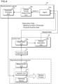
FIG. 4 is a functional block diagram of theinjection molding machine 2 according to the first embodiment. As illustrated inFIG. 4 , thecontrol unit 15 includes anobservation unit 15a and areward calculation unit 15b. Physical quantity data acquired from themeasurement unit 3 via theacquisition unit 14 is input to theobservation unit 15a. - The
observation unit 15a observes states of theinjection molding machine 2 and the molded product by analyzing physical quantity data, and outputs observation data obtained by observation to anagent 16a of thereinforcement learner 16. Since the physical quantity data has a large amount of information, it is preferable that theobservation unit 15a generate observation data by compressing information of the physical quantity data as necessary. The observation data is information indicating the state of theinjection molding machine 2, the state of the molded product, etc. Further, the observation data preferably includes a molding condition parameter set in thecontrol device 23. - For example, the
observation unit 15a calculates observation data indicating a feature amount indicating an external feature of the molded product, dimensions, area, and volume of the molded product, the amount of optical axis deviation of an optical part (molded product), etc. based on a camera image and a measurement value of the laser displacement sensor. Further, theobservation unit 15a preferably performs preprocessing on time-series waveform data such as injection speed, injection pressure, holding pressure, etc., and extracts a feature amount of the time-series waveform data as observation data. Note that time-series data of a time-series waveform or image data representing a time-series waveform may be used as observation data. - Furthermore, the
observation unit 15a calculates defectiveness of the molded product by analyzing physical quantity data, and outputs the calculated and obtained defectiveness to thereward calculation unit 15b. Examples of the defectiveness include the area of burrs, the area of shorts, the amount of deformation such as sink marks, warping, and twisting, a length of a weld line, a size of a silver streak, a degree of jetting, a size of a flow mark, the amount of change of color due to uneven coloring, etc. Moreover, the defectiveness may be the amount of change in observation data obtained from the molding machine from observation data serving as a criterion for non-defective products. - The
reward calculation unit 15b calculates reward data serving as a criterion for quality of a molding condition parameter based on the defectiveness output from theobservation unit 15a, and outputs the calculated reward data to theagent 16a of thereinforcement learner 16. - As illustrated in
FIG. 4 , thereinforcement learner 16 includes theagent 16a, a changetiming determining unit 16b, and aparameter changing unit 16c. - The
agent 16a is, for example, a reinforcement learning model having a deep neural network such as DQN, A3C, or D4PG, or a model-based reinforcement learning model such as PlaNet or SLAC. - In the case of a reinforcement learning model having a deep neural network, the
agent 16a includes a DQN (Deep Q-Network), and determines an action a corresponding to a state s of theinjection molding machine 2 indicated by observation data based on the state s. The DQN is a neural network model that outputs a value of each of a plurality of actions a when a state s indicating observation data is input. The plurality of actions a corresponds to change values of the molding condition parameters. A change value may be a value of a molding condition parameter after change, or may be the amount of change in a molding condition parameter. Here, it is assumed that action a is a molding condition parameter value. In the first embodiment, the change value is described as a value of a molding condition parameter. An action having a high value represents an appropriate molding condition parameter to be set ininjection molding machine 2. The action a causes theinjection molding machine 2 to transition to another state. After state transition, theagent 16a receives a reward calculated by thereward calculation unit 15b, and trains theagent 16a so that a profit, that is, accumulation of rewards is maximized. - More specifically, the DQN has an input layer, an intermediate layer, and an output layer. The input layer includes a plurality of nodes to which the state s, that is, observation data is input. The output layer includes a plurality of nodes that corresponds to a plurality of actions a, respectively, and outputs a value Q(s, a) of a corresponding action a in an input state s.
- The DQN of the
agent 16a can be reinforcement-trained by adjusting various weighing coefficients characterizing the DQN using the value Q expressed by the following formula (1) as training data based on a state s, an action a, and a reward obtained by the action.
- s: state
- a: action
- α: learning coefficient
- r: reward
- γ: discount rate
- maxQ(snext, anext): maximum value among Q-values for next possible action
- In the case of a model-based reinforcement learning model, the
agent 16a is provided with a state representation map and uses the state representation map as a guide for action determination to determine a molding condition parameter (action a). Using the state representation map, theagent 16a determines a molding condition parameter (action a) corresponding to the state s of theinjection molding machine 2 indicated by the observation data based on the state s. - For example, the state representation map is a model in which, when observation data (state s) and a molding condition parameter (action a) are input, a reward r for taking the molding condition parameter (action a) in the state s and a probability (certainty) Pt of state transition to a next state s' are output. The reward r can be regarded as information indicating whether or not a molded product obtained when a certain molding condition parameter (behavior a) is set in the state s is normal. In the case of being in the state, the action a is a molding condition parameter that needs to be set in the
injection molding machine 2. The action a causes theinjection molding machine 2 to transition to another state. After the state transition, theagent 16a receives a reward calculated by thereward calculation unit 15b and updates the state representation map. - When a plurality of molding condition parameters is changed by the action a determined by the
agent 16a, the changetiming determining unit 16b refers to the table 12b and determines change timings of the plurality of parameters determined to be changed. - The
parameter changing unit 16c sequentially changes the plurality of molding condition parameters determined to be changed according to the change timings determined by the changetiming determining unit 16b. A timing at which setting of the molding condition parameters is actually changed is preferably after a weighing completion time of a molding material and before start of a next cycle. Then, theparameter changing unit 16c outputs a control signal based on the changed molding condition parameters to theinjection unit 21 and theclamping device 22. Theinjection unit 21 and theclamping device 22 operate according to the control signal based on the changed molding condition parameters. -
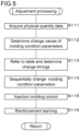
FIG. 5 is a flowchart illustrating a processing procedure of theprocessor 11 according to the first embodiment. It is assumed that initial values of the molding condition parameters are set in theinjection molding machine 2, and the molding process cycle is repeated. The initial values of the molding condition parameters are adjusted according to the states of theinjection molding machine 2 and the molded product. - When the
injection molding machine 2 executes molding, themeasurement unit 3 measures physical quantities related to theinjection molding machine 2 and the molded product, and theprocessor 11 or theacquisition unit 14 as a functional unit acquires physical quantity data obtained by measurement by the measurement unit 3 (step S111). - Next, the
processor 11 or theagent 16a determines change values of the molding condition parameters based on the acquired physical quantity data (step S112). - Specifically, the
observation unit 15a of thecontrol unit 15 generates observation data based on the acquired physical quantity data, and outputs the generated observation data to theagent 16a of thereinforcement learner 16. - The
agent 16a of thereinforcement learner 16 acquires the observation data output from theobservation unit 15a, and calculates change values (actions a) of the molding condition parameters of theinjection molding machine 2 based on the observation data. Theagent 16a outputs the calculated molding condition parameters (actions a) to the changetiming determining unit 16b. It is preferable that theagent 16a selects an optimal action a in an operation phase (inference phase), and determines an exploratory action a in the learning phase in order to reinforcement-train theagent 16a. In addition, theagent 16a may use an objective function to select an action a with a small value of the objective function. The objective function is a function which value is smaller the higher the action value and the more unexplored the action is, and which value is larger when the amount of change from a current molding condition is greater than a predetermined range. - When there is a plurality of objects to be changed, the
processor 11 or the changetiming determining unit 16b completing processing of step S112 refers to the table 12b and determines change timings of the plurality of molding condition parameters, that is, a change order (step S113). - Then, the
processor 11 or theparameter changing unit 16c sequentially changes the plurality of molding condition parameters to be changed according to the determined change timings (step S114). When the molding condition parameters are changed, theprocessor 11 or theparameter changing unit 16c outputs a control signal based on the molding condition parameters to theinjection unit 21 and theclamping device 22 to control the operation of the injection molding machine 2 (step S115). Theinjection unit 21 and theclamping device 22 of theinjection molding machine 2 perform injection molding processing according to the control signal based on the molding condition parameters output from theparameter changing unit 16c. - The
processor 11 executes reinforcement learning processing for theagent 16a in the learning phase (step S116). Note that, when the plurality of molding condition parameters is changed to perform reinforcement learning for theagent 16a, a reward may be calculated to reinforcement-train theagent 16a after changing all the plurality of molding condition parameters in processing of steps S113 and S114. In addition, after changing all the plurality of molding condition parameters in processing of steps S113 and S114, a reward may be further calculated after a predetermined number of times to perform reinforcement learning. The predetermined number of times may be a different value depending on the plurality of molding condition parameters to be changed. - Specifically, in step S116, the
measurement unit 3 measures physical quantities related to theinjection molding machine 2 and the molded product after changing the molding condition parameters, and outputs the measured physical quantity data. Theacquisition unit 14 acquires the physical quantity data, and the acquired physical quantity data is input to theobservation unit 15a. - The
observation unit 15a of thecontrol unit 15 acquires the physical quantity data output from themeasurement unit 3 via theacquisition unit 14, generates observation data based on the acquired physical quantity data, and outputs the generated observation data to theagent 16a of thereinforcement learner 16. Further, thereward calculation unit 15b calculates reward data determined according to defectiveness of the molded product based on the physical quantity data measured by themeasurement unit 3, and outputs the calculated reward data to thereinforcement learner 16. - The
agent 16a updates the model based on the observation data output from theobservation unit 15a and the reward data output from thereward calculation unit 15b. When theagent 16a is the DQN, the DQN is trained using the value expressed by the above equation (1) as training data. -
FIGS. 6A and6B are explanatory diagrams illustrating effects of the molding condition parameter adjusting method according to the first embodiment. The effects of the molding condition parameter adjustment method according to the first embodiment will be described using, as an example, the case where the weighing completion position of the molding material and the injection speed switching position are changed as a plurality of molding condition parameters. -
FIG. 6A illustrates a state in which the molding condition parameters are changed without considering the change timings, andFIG. 6B illustrates a state in which the molding condition parameters are changed in consideration of the change timings. Main processes in the molding process cycle include an eject retraction process ("EJ retreat" inFIG. 6A andFIG. 6B ), a mold closing process, a mold clamping process, an injection process, a pressure holding process, a weighing process, a mold opening process, and an eject advance process ("EJ advance" inFIG. 6A andFIG. 6B ), and the respective processes are sequentially performed. - When the "weighing completion position" and the "injection speed switching position" are changed, the "injection speed switching position" needs to be actually changed after the "weighing completion position" is first actually changed. As illustrated in
FIG. 6A , it is assumed that an instruction to change the "weighing completion position" and an instruction to change the "injection speed switching position" are issued at the same time when an n-cycle weighing process is completed. In this case, upon completion of n-cycle eject advance, settings of the "weighing completion position" and the "injection speed switching position" are changed at the same time. - However, even though the "injection speed switching position" is actually changed, the actual position of the screw 21b according to the "weighing completion position" is not changed. In an n-cycle, weighing has already been completed using the molding condition parameter of the "weighing completion position" before change, and the position of the screw 21b at the start of an (n+1)-cycle is a position when controlled by the "weighing completion position" before parameter change. After changing setting of "weighing completion position", setting is reflected as the position of the screw 21b in the weighing process in the (n+1)-cycle, which is a process after the injection process in the (n+1)-cycle.
- Therefore, in the (n+1)-cycle injection process, when only the "injection speed switching position" is actually changed while the "weighing completion position" is not actually reflected as the position of the screw 21b, unexpected defectiveness occurs. For example, a defect may occur where a degree of shorts is so severe that the molded product cannot be removed from the mold. In the worst case, there is concern that the mold may be damaged.
- In order to prevent such a defect, in the first embodiment, the table 12b having information indicating a mutual relationship between change timings of a plurality of molding condition parameters is prepared. When the plurality of molding condition parameters is changed, the molding condition
parameter adjustment device 1 refers to the table 12b and determines a change timing of each molding condition parameter. The molding conditionparameter adjustment device 1 sequentially performs changes according to the determined change timings. - Specifically, when the "weighing completion position" and the "injection speed switching position" are changed, as illustrated in
FIG. 6B , first, an instruction to change the "weighing completion position" is issued at the end of the weighing process in the current n-cycle. In this way, setting of the "weighing completion position" is changed upon completion of n-cycle eject advance, and the "weighing completion position" is actually changed and the molding material is weighed in an (n+1)-cycle weighing process. Meanwhile, an instruction to change the "injection speed switching position" is issued at the end of the weighing process in the (n+1)-cycle, which is one cycle after the time when the "weighing completion position" is changed. In this way, setting of the "injection speed switching position" is changed upon completion of (n+1)-cycle eject advance, and the "injection speed switching position" is actually changed and injection is performed in (n+2)-cycle injection and pressure holding processes. - Therefore, in the injection process, it is possible to avoid a situation where only the "injection speed switching position" is changed without the change in the "weighing completion position" being reflected in the position of the screw 21b.
- According to the
injection molding machine 2 according to the first embodiment, it is possible to adjust the plurality of molding condition parameters of theinjection molding machine 2 in the molding process cycle in an appropriate order and timing, taking into consideration the mutual relationship between the plurality of molding process parameters. - Specifically, the molding condition
parameter adjustment device 1 can change the weighing completion position and the injection speed switching position at an appropriate timing and order. - Furthermore, the molding condition
parameter adjustment device 1 can change the heating temperature and the injection speed switching position of the heating cylinder 21a at an appropriate timing and order. - Note that, even though a description has been given in the first embodiment using an example of changing the molding condition parameters in the operation phase or the learning phase of reinforcement learning, the invention can also be applied when the molding condition parameters are changed in other machine learning to be described later. Further, the invention can also be applied when changing the molding condition parameters in the case of creating a learning data set for machine learning. The invention can also be applied when it is necessary to change a plurality of molding condition parameters for any purpose not using machine learning.
- In addition, even though a description has been given of an example in which a plurality of molding condition parameters is adjusted using reinforcement learning, the molding condition
parameter adjustment device 1 may include a learner trained by supervised learning. The learner is a model that outputs a change value of a molding condition parameter that improves a state of a molded product when observation data is input. The learner may be a model having a CNN (Convolution Neural Network) such as ResNet or DenseNet that recognizes observation data, or may be a model having a recurrent neural network (RNN), LSTM, Vision Transformer, etc. that recognizes observation data that is time-series information when the observation data is time-series data. In addition, the learner may be configured using a learning model having a configuration other than the above-mentioned CNN, RNN, etc., such as a neural network, Vision Transformer, SVM (Support Vector Machine), Bayesian network, or a decision tree such as XGBoost. - In addition, even though the
injection molding machine 2 that performs resin molding has been described as an example of a molding machine, the invention may also be applied to a hollow molding machine, a film molding machine, an extruder, a twin-screw extruder, a spinning extruder, a granulator, etc. Further, the molding material is not limited to resin, and the invention may be applied to a magnesium injection molding machine, etc. -
- 1
- Molding condition parameter adjustment device
- 2
- Injection molding machine
- 3
- Measurement unit
- 4
- Recording medium
- 11
- Processor
- 12
- Storage unit
- 12a
- Computer program
- 12b
- Table
- 13
- Operation unit
- 14
- Acquisition unit
- 15
- Control unit
- 15a
- Observation unit
- 15b
- Reward calculation unit
- 16
- Reinforcement learner
- 16a
- Agent
- 16b
- Adjustment unit
- 21
- Injection unit
- 21a
- Heating cylinder
- 21b
- Screw
- 21c
- Hopper
- 21d
- Heater
- 22
- Clamping device
- 23
- Control device
Claims (6)
- A method of adjusting a molding condition parameter of a molding machine, the method comprising:determining change values of a plurality of molding condition parameters set in the molding machine in a molding process cycle;determining change timings of the plurality of parameters determined as objects to be changed with reference to timing information when the change values of the plurality of molding condition parameters are determined, the timing information indicating a sequence relationship of the change timings of the plurality of parameters in the molding process cycle; andsequentially changing the plurality of parameters determined as objects to be changed according to the determined change timings.
- The method according to claim 1, wherein:the molding machine is an injection molding machine having a heating cylinder and a screw for weighing, plasticizing, and injecting a molding material,the plurality of molding condition parameters includes a weighing completion position of the molding material and an injection speed switching position, andthe timing information includes information indicating that the weighing completion position is changed first and the injection speed is changed in a molding process cycle that is one molding process cycle after a molding process cycle in which the weighing completion position is changed.
- The method according to claim 1 or 2, wherein:the molding machine is an injection molding machine having a heating cylinder and a screw for weighing, plasticizing, and injecting a molding material,the plurality of molding condition parameters includes a heating temperature of the heating cylinder and an injection speed switching position, andthe timing information includes information indicating that the heating temperature of the heating cylinder is changed first and the injection speed is changed in a molding process cycle that is a predetermined number of times after a molding process cycle in which the heating temperature is changed.
- A computer program for causing a computer to adjust molding condition parameters of a molding machine, the computer program causing the computer to perform processes of:determining change values of a plurality of molding condition parameters set in the molding machine in a molding process cycle;determining change timings of the plurality of parameters determined as objects to be changed with reference to timing information when the change values of the plurality of molding condition parameters are determined, the timing information indicating a sequence relationship of the change timings of the plurality of parameters in the molding process cycle; andsequentially changing the plurality of parameters determined as objects to be changed according to the determined change timings.
- A molding condition parameter adjustment device configured to adjust a plurality of molding condition parameters set in a molding machine, the molding condition parameter adjustment device comprising:a storage unit configured to store timing information indicating a sequence relationship of change timings of the plurality of parameters in a molding process cycle; anda processor, wherein the processor is configured to:determine change values of the plurality of molding condition parameters in the molding process cycle,determine the change timings of the plurality of parameters determined as objects to be changed with reference to the timing information stored by the storage unit when the change values of the plurality of molding condition parameters are determined, andsequentially change the plurality of parameters determined as objects to be changed according to the determined change timings.
- A molding machine operating according to a plurality of set molding condition parameters, the molding machine comprising:the molding condition parameter adjustment device according to claim 5,wherein the molding machine is configured to change the plurality of molding condition parameters by the molding condition parameter adjustment device.
Applications Claiming Priority (2)
| Application Number | Priority Date | Filing Date | Title |
|---|---|---|---|
| JP2021141522A JP7546532B2 (en) | 2021-08-31 | 2021-08-31 | Molding condition parameter adjustment method, computer program, molding condition parameter adjustment device, and molding machine |
| PCT/JP2022/022335 WO2023032375A1 (en) | 2021-08-31 | 2022-06-01 | Method for adjusting molding condition parameters, computer program, device for adjusting molding condition parameters, and molding machine |
Publications (4)
| Publication Number | Publication Date |
|---|---|
| EP4397468A1 true EP4397468A1 (en) | 2024-07-10 |
| EP4397468A4 EP4397468A4 (en) | 2025-08-06 |
| EP4397468B1 EP4397468B1 (en) | 2026-01-28 |
| EP4397468C0 EP4397468C0 (en) | 2026-01-28 |
Family
ID=85411175
Family Applications (1)
| Application Number | Title | Priority Date | Filing Date |
|---|---|---|---|
| EP22863963.9A Active EP4397468B1 (en) | 2021-08-31 | 2022-06-01 | Method for adjusting molding condition parameters, computer program, device for adjusting molding condition parameters, and molding machine |
Country Status (6)
| Country | Link |
|---|---|
| US (1) | US20240367359A1 (en) |
| EP (1) | EP4397468B1 (en) |
| JP (1) | JP7546532B2 (en) |
| CN (1) | CN117881518A (en) |
| TW (1) | TW202311006A (en) |
| WO (1) | WO2023032375A1 (en) |
Families Citing this family (1)
| Publication number | Priority date | Publication date | Assignee | Title |
|---|---|---|---|---|
| CN120632586A (en) * | 2025-08-15 | 2025-09-12 | 克劳斯玛菲机械(中国)有限公司 | Prediction method and prediction system for screw minimum position and check ring failure |
Family Cites Families (7)
| Publication number | Priority date | Publication date | Assignee | Title |
|---|---|---|---|---|
| JPS63132020A (en) * | 1986-11-22 | 1988-06-04 | Sumitomo Heavy Ind Ltd | Apparatus for continuous operation of injection molding machine |
| DE4219259A1 (en) * | 1992-06-12 | 1993-12-16 | Karl Hehl | Process for controlling a plastic injection molding machine |
| ES2985737T3 (en) * | 2016-02-22 | 2024-11-07 | Kistler Holding Ag | Procedure for carrying out a cyclical production process |
| JP7265318B2 (en) | 2018-03-23 | 2023-04-26 | 株式会社日本製鋼所 | Injection molding machine system that adjusts molding conditions using machine learning |
| JP6825055B2 (en) * | 2019-03-27 | 2021-02-03 | 株式会社日立製作所 | Injection molding support system, molding condition correction system, injection molding support method, molding condition correction method and computer program |
| JP7099977B2 (en) * | 2019-03-27 | 2022-07-12 | 株式会社日立製作所 | Injection molding analysis method and injection molding analysis system |
| JP7344754B2 (en) * | 2019-10-23 | 2023-09-14 | 株式会社日本製鋼所 | Learning model generation method, computer program, setting value determination device, molding machine and molding device system |
-
2021
- 2021-08-31 JP JP2021141522A patent/JP7546532B2/en active Active
-
2022
- 2022-06-01 EP EP22863963.9A patent/EP4397468B1/en active Active
- 2022-06-01 WO PCT/JP2022/022335 patent/WO2023032375A1/en not_active Ceased
- 2022-06-01 CN CN202280058554.XA patent/CN117881518A/en active Pending
- 2022-06-01 US US18/685,869 patent/US20240367359A1/en active Pending
- 2022-06-22 TW TW111123181A patent/TW202311006A/en unknown
Also Published As
| Publication number | Publication date |
|---|---|
| TW202311006A (en) | 2023-03-16 |
| JP2023034971A (en) | 2023-03-13 |
| EP4397468A4 (en) | 2025-08-06 |
| EP4397468B1 (en) | 2026-01-28 |
| JP7546532B2 (en) | 2024-09-06 |
| CN117881518A (en) | 2024-04-12 |
| EP4397468C0 (en) | 2026-01-28 |
| WO2023032375A1 (en) | 2023-03-09 |
| US20240367359A1 (en) | 2024-11-07 |
Similar Documents
| Publication | Publication Date | Title |
|---|---|---|
| CN114846482B (en) | Operation quantity determination device, molding device system, molding machine, computer program, operation quantity determination method and status display device | |
| JP7344754B2 (en) | Learning model generation method, computer program, setting value determination device, molding machine and molding device system | |
| CN116075409B (en) | Machine learning methods, computer program products, machine learning devices and molding machines | |
| EP4397468B1 (en) | Method for adjusting molding condition parameters, computer program, device for adjusting molding condition parameters, and molding machine | |
| CN116997913B (en) | Reinforcement learning methods, program products, reinforcement learning devices, molding machines, and storage media | |
| JP7530687B2 (en) | Information processing device, information processing system, and program | |
| JP7638816B2 (en) | MOLDING CONDITION ADJUSTMENT METHOD, COMPUTER PROGRAM, MOLDING CONDITION ADJUSTMENT DEVICE, AND INJECTION MOLDING MACHINE | |
| EP4378658A1 (en) | Data set creation method, trained model generation method, computer program, and data set creation device | |
| JP2026017235A (en) | Reinforcement learning device, injection molding machine, reinforcement learning method, and computer program | |
| EP4454855A1 (en) | Operating condition correction method, operating condition correction device, molding machine and computer program | |
| CN117921966A (en) | Information processing device, injection molding machine, and program |
Legal Events
| Date | Code | Title | Description |
|---|---|---|---|
| STAA | Information on the status of an ep patent application or granted ep patent |
Free format text: STATUS: THE INTERNATIONAL PUBLICATION HAS BEEN MADE |
|
| PUAI | Public reference made under article 153(3) epc to a published international application that has entered the european phase |
Free format text: ORIGINAL CODE: 0009012 |
|
| STAA | Information on the status of an ep patent application or granted ep patent |
Free format text: STATUS: REQUEST FOR EXAMINATION WAS MADE |
|
| 17P | Request for examination filed |
Effective date: 20240314 |
|
| AK | Designated contracting states |
Kind code of ref document: A1 Designated state(s): AL AT BE BG CH CY CZ DE DK EE ES FI FR GB GR HR HU IE IS IT LI LT LU LV MC MK MT NL NO PL PT RO RS SE SI SK SM TR |
|
| DAV | Request for validation of the european patent (deleted) | ||
| DAX | Request for extension of the european patent (deleted) | ||
| A4 | Supplementary search report drawn up and despatched |
Effective date: 20250708 |
|
| RIC1 | Information provided on ipc code assigned before grant |
Ipc: B29C 45/76 20060101AFI20250702BHEP Ipc: B29C 45/78 20060101ALI20250702BHEP |
|
| GRAP | Despatch of communication of intention to grant a patent |
Free format text: ORIGINAL CODE: EPIDOSNIGR1 |
|
| STAA | Information on the status of an ep patent application or granted ep patent |
Free format text: STATUS: GRANT OF PATENT IS INTENDED |
|
| INTG | Intention to grant announced |
Effective date: 20250915 |
|
| GRAS | Grant fee paid |
Free format text: ORIGINAL CODE: EPIDOSNIGR3 |
|
| GRAA | (expected) grant |
Free format text: ORIGINAL CODE: 0009210 |
|
| STAA | Information on the status of an ep patent application or granted ep patent |
Free format text: STATUS: THE PATENT HAS BEEN GRANTED |
|
| AK | Designated contracting states |
Kind code of ref document: B1 Designated state(s): AL AT BE BG CH CY CZ DE DK EE ES FI FR GB GR HR HU IE IS IT LI LT LU LV MC MK MT NL NO PL PT RO RS SE SI SK SM TR |
|
| REG | Reference to a national code |
Ref country code: CH Ref legal event code: F10 Free format text: ST27 STATUS EVENT CODE: U-0-0-F10-F00 (AS PROVIDED BY THE NATIONAL OFFICE) Effective date: 20260128 Ref country code: GB Ref legal event code: FG4D |
|
| REG | Reference to a national code |
Ref country code: DE Ref legal event code: R096 Ref document number: 602022029502 Country of ref document: DE |
|
| REG | Reference to a national code |
Ref country code: IE Ref legal event code: FG4D |
|
| U01 | Request for unitary effect filed |
Effective date: 20260219 |
|
| U07 | Unitary effect registered |
Designated state(s): AT BE BG DE DK EE FI FR IT LT LU LV MT NL PT RO SE SI Effective date: 20260225 |