EP4397418A1 - Glue gun - Google Patents
Glue gun Download PDFInfo
- Publication number
- EP4397418A1 EP4397418A1 EP23204376.0A EP23204376A EP4397418A1 EP 4397418 A1 EP4397418 A1 EP 4397418A1 EP 23204376 A EP23204376 A EP 23204376A EP 4397418 A1 EP4397418 A1 EP 4397418A1
- Authority
- EP
- European Patent Office
- Prior art keywords
- carrier
- glue
- knob
- housing
- actuator
- Prior art date
- Legal status (The legal status is an assumption and is not a legal conclusion. Google has not performed a legal analysis and makes no representation as to the accuracy of the status listed.)
- Withdrawn
Links
Images







Classifications
-
- B—PERFORMING OPERATIONS; TRANSPORTING
- B05—SPRAYING OR ATOMISING IN GENERAL; APPLYING FLUENT MATERIALS TO SURFACES, IN GENERAL
- B05C—APPARATUS FOR APPLYING FLUENT MATERIALS TO SURFACES, IN GENERAL
- B05C17/00—Hand tools or apparatus using hand held tools, for applying liquids or other fluent materials to, for spreading applied liquids or other fluent materials on, or for partially removing applied liquids or other fluent materials from, surfaces
- B05C17/005—Hand tools or apparatus using hand held tools, for applying liquids or other fluent materials to, for spreading applied liquids or other fluent materials on, or for partially removing applied liquids or other fluent materials from, surfaces for discharging material from a reservoir or container located in or on the hand tool through an outlet orifice by pressure without using surface contacting members like pads or brushes
- B05C17/00523—Hand tools or apparatus using hand held tools, for applying liquids or other fluent materials to, for spreading applied liquids or other fluent materials on, or for partially removing applied liquids or other fluent materials from, surfaces for discharging material from a reservoir or container located in or on the hand tool through an outlet orifice by pressure without using surface contacting members like pads or brushes provided with means to heat the material
- B05C17/00526—Hand tools or apparatus using hand held tools, for applying liquids or other fluent materials to, for spreading applied liquids or other fluent materials on, or for partially removing applied liquids or other fluent materials from, surfaces for discharging material from a reservoir or container located in or on the hand tool through an outlet orifice by pressure without using surface contacting members like pads or brushes provided with means to heat the material the material being supplied to the apparatus in a solid state, e.g. rod, and melted before application
- B05C17/0053—Hand tools or apparatus using hand held tools, for applying liquids or other fluent materials to, for spreading applied liquids or other fluent materials on, or for partially removing applied liquids or other fluent materials from, surfaces for discharging material from a reservoir or container located in or on the hand tool through an outlet orifice by pressure without using surface contacting members like pads or brushes provided with means to heat the material the material being supplied to the apparatus in a solid state, e.g. rod, and melted before application the driving means for the material being manual, mechanical or electrical
-
- B—PERFORMING OPERATIONS; TRANSPORTING
- B05—SPRAYING OR ATOMISING IN GENERAL; APPLYING FLUENT MATERIALS TO SURFACES, IN GENERAL
- B05C—APPARATUS FOR APPLYING FLUENT MATERIALS TO SURFACES, IN GENERAL
- B05C17/00—Hand tools or apparatus using hand held tools, for applying liquids or other fluent materials to, for spreading applied liquids or other fluent materials on, or for partially removing applied liquids or other fluent materials from, surfaces
- B05C17/005—Hand tools or apparatus using hand held tools, for applying liquids or other fluent materials to, for spreading applied liquids or other fluent materials on, or for partially removing applied liquids or other fluent materials from, surfaces for discharging material from a reservoir or container located in or on the hand tool through an outlet orifice by pressure without using surface contacting members like pads or brushes
- B05C17/01—Hand tools or apparatus using hand held tools, for applying liquids or other fluent materials to, for spreading applied liquids or other fluent materials on, or for partially removing applied liquids or other fluent materials from, surfaces for discharging material from a reservoir or container located in or on the hand tool through an outlet orifice by pressure without using surface contacting members like pads or brushes with manually mechanically or electrically actuated piston or the like
- B05C17/014—Hand tools or apparatus using hand held tools, for applying liquids or other fluent materials to, for spreading applied liquids or other fluent materials on, or for partially removing applied liquids or other fluent materials from, surfaces for discharging material from a reservoir or container located in or on the hand tool through an outlet orifice by pressure without using surface contacting members like pads or brushes with manually mechanically or electrically actuated piston or the like comprising means for preventing oozing
Definitions
- Glue is typically utilized in applications for joining two or more objects or entities.
- the glue may be applied to said objects or entities through a plurality of means.
- glue may be melted and applied to said objects or entities as hot glue.
- Hot glue provides an adhesive between the objects or entities that cools and hardens between the objects or entities to join the objects or entities.
- FIG. 1 illustrates a glue gun 10 according to an embodiment of the disclosure.
- the glue gun 10 is configured to receive a glue stick 4 and to selectively melt the glue stick 4 for adhering a workpiece or workpieces.
- the glue gun 10 includes a housing 14, an output nozzle 18, a stroke adjustment mechanism 22, a trigger assembly 26, and a carrier 30.
- the housing 14 includes a first housing portion or main housing portion 34 that has a first end 38 and a second end 42 that is opposite the first end 38, and a second housing portion or handle housing portion 46 that extends from the main housing portion 34 at a location that is between the first end 38 and the second end 42.
- Each of the main housing portion 34 and the handle housing portion 46 may be formed of housing halves or in any other manner to form the shell of the glue gun 10.
- the handle housing portion 46 is configured to be grasped by a user for operation of the glue gun 10.
- the output nozzle 18 is positioned at the first end 38 of the main housing portion 34 and dispenses glue during operation of the glue gun 10.
- the glue gun 10 includes a heating element 54 and a battery receptacle 58.
- the heating element 54 is disposed in the main housing portion 34 proximate the first end 38 (e.g., adjacent the output nozzle 18) to selectively heat and melt a front portion of the glue stick 4.
- the battery receptacle 58 is located at a distal end of the handle housing portion 46, and a battery pack may be attached to the battery receptacle 58 to provide power to the heating element 54.
- the disclosure provides a glue gun in which the housing defines an opening between the first end and the second end of the housing, and wherein the carrier is visible via the opening in any position between the first position and the second position.
Landscapes
- Engineering & Computer Science (AREA)
- Mechanical Engineering (AREA)
- Coating Apparatus (AREA)
Abstract
Description
- The disclosure relates to glue guns, and more specifically, hot glue guns.
- Glue is typically utilized in applications for joining two or more objects or entities. The glue may be applied to said objects or entities through a plurality of means. In some instances, glue may be melted and applied to said objects or entities as hot glue. Hot glue provides an adhesive between the objects or entities that cools and hardens between the objects or entities to join the objects or entities.
- In one aspect, the disclosure provides a glue gun including a housing, an actuator, a carrier, and a stroke adjustment mechanism. The housing extends along an axis and includes a first end and a second end opposite the first end. The first end includes an outlet configured to dispense glue from the housing. The actuator is coupled to the housing. The carrier is supported by the housing and is configured to support a glue stick. The carrier is coupled to the actuator and movable a distance along the axis in response to actuation of the actuator to guide the glue stick toward the first end. The stroke adjustment mechanism is coupled to the carrier to adjust the distance that the carrier is movable along the axis.
- In another aspect, the disclosure provides a glue gun including a housing, an actuator, a carrier, and a knob. The housing extends along an axis and includes a first end and a second end opposite the first end. The first end includes an outlet configured to dispense glue from the housing. The actuator is coupled to the housing. The carrier is supported by the housing and is configured to support a glue stick. The carrier is coupled to the actuator and movable a distance along the axis in response to actuation of the actuator to guide the glue stick toward the first end. The knob is positioned on or adjacent the second end and includes an aperture that is configured to receive and surround a glue stick after insertion of the glue stick into the housing.
- In another aspect, the disclosure provides a glue gun including a housing, a trigger assembly, and a carrier. The housing extends along an axis and includes a first end and a second end opposite the first end. The first end includes an outlet configured to dispense glue from the housing. The trigger assembly includes a linkage mechanism and a trigger. The linkage mechanism has a first linkage coupled to the carrier and a second linkage. The trigger is operably coupled to the second linkage. The trigger is actuatable to translate the linkage mechanism and the carrier toward the first end of the housing. The carrier is supported by the housing and is configured to support a glue stick. The carrier is coupled to the actuator and movable a distance along the axis in response to actuation of the trigger to guide the glue stick toward the first end.
-
-
FIG. 1 is a perspective view of a glue gun including a housing, a stroke adjustment mechanism, a trigger assembly, and a carrier according to an embodiment of the disclosure. -
FIG. 2 is a section view of the glue gun ofFIG. 1 taken along line 2-2 and illustrating the stroke adjustment mechanism, the trigger assembly, the carrier and a heating element. -
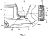
FIG. 3 is an enlarged side view of a rear portion of the glue gun ofFIG. 1 . -
FIG. 4 is a rear perspective view of a portion of the glue gun. -
FIG. 5 is an enlarged side view of the glue gun with the stroke adjustment mechanism at a first position and with a portion of the housing removed. -
FIG. 6 is an enlarged side view of the glue gun with the stroke adjustment mechanism at a second position and with a portion of the housing removed. -
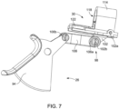
FIG. 7 is a perspective view of the trigger assembly and the carrier of the glue gun. -
FIG. 8 is an exploded view of the trigger assembly and the carrier of the glue gun. -
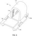
FIG. 9 is a perspective view of the carrier. -
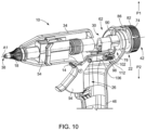
FIG. 10 is a side view of a portion of the glue gun illustrating the carrier in a selected position among a plurality of available positions and the trigger in a first or unactuated state. -
FIG. 11 is a side view of a portion of the glue gun illustrating the carrier pulled forward by movement of the trigger to a second or actuated state. -
FIG. 12 is an enlarged section view of the glue gun with the stroke adjustment mechanism at the first position. -
FIG. 13 is an enlarged section view of the glue gun with the stroke adjustment mechanism at the second position. - Before any embodiments of the invention are explained in detail, it is to be understood that the invention is not limited in its application to the details of construction and the arrangement of components set forth in the following description or illustrated in the following drawings. The invention is capable of other embodiments and of being practiced or of being carried out in various ways. Also, it is to be understood that the phraseology and terminology used herein is for the purpose of description and should not be regarded as limiting.
- The detailed description uses numerical and letter designations to refer to features in the drawings. Like or similar designations in the drawings and description have been used to refer to like or similar parts of the invention.
- The singular forms "a," "an," and "the" include plural references unless the context clearly dictates otherwise. The terms "coupled," "fixed," and the like refer to both direct coupling or fixing, as well as indirect coupling or fixing through one or more intermediate components or features, unless otherwise specified herein. As used herein, the terms "includes," "including," "has," "having" or any other variation thereof, are intended to cover a non-exclusive inclusion. For example, a process, method, article, or apparatus that comprises a list of features is not necessarily limited only to those features but may include other features not expressly listed or inherent to such process, method, article, or apparatus. Further, unless expressly stated to the contrary, "or" refers to an inclusive- or and not to an exclusive- or. For example, a condition A or B is satisfied by any one of the following: A is true (or present) and B is false (or not present), A is false (or not present) and B is true (or present), and both A and B are true (or present).
- Benefits, other advantages, and solutions to problems are described below with regard to specific embodiments. However, the benefits, advantages, solutions to problems, and any feature(s) that may cause any benefit, advantage, or solution to occur or become more pronounced are not to be construed as a critical, required, or essential feature of any or all the claims.
-
FIG. 1 illustrates aglue gun 10 according to an embodiment of the disclosure. Theglue gun 10 is configured to receive a glue stick 4 and to selectively melt the glue stick 4 for adhering a workpiece or workpieces. As illustrated inFIGS. 1 and2 , theglue gun 10 includes ahousing 14, anoutput nozzle 18, astroke adjustment mechanism 22, atrigger assembly 26, and acarrier 30. Thehousing 14 includes a first housing portion ormain housing portion 34 that has afirst end 38 and asecond end 42 that is opposite thefirst end 38, and a second housing portion or handlehousing portion 46 that extends from themain housing portion 34 at a location that is between thefirst end 38 and thesecond end 42. Each of themain housing portion 34 and thehandle housing portion 46 may be formed of housing halves or in any other manner to form the shell of theglue gun 10. Thehandle housing portion 46 is configured to be grasped by a user for operation of theglue gun 10. Theoutput nozzle 18 is positioned at thefirst end 38 of themain housing portion 34 and dispenses glue during operation of theglue gun 10. - With continued reference to
FIGS. 1 and2 , theglue gun 10 includes aheating element 54 and abattery receptacle 58. Theheating element 54 is disposed in themain housing portion 34 proximate the first end 38 (e.g., adjacent the output nozzle 18) to selectively heat and melt a front portion of the glue stick 4. Thebattery receptacle 58 is located at a distal end of thehandle housing portion 46, and a battery pack may be attached to thebattery receptacle 58 to provide power to theheating element 54. - With reference to
FIG. 3 , themain housing portion 34 includes an opening orgap 62 adjacent thesecond end 42. Theopening 62 is located closer to thesecond end 42 than thefirst end 38 and provides a visual of a rear end of the glue stick 4 and the position of thecarrier 30 relative to a first (e.g., minimum) start position and a second (e.g., maximum) start position. With additional reference toFIG. 2 , the first start position corresponds to a position in which thetrigger assembly 26 is pulled the smallest amount or minimum distance and thecarrier 30 is moved a minimum stroke length along the axis A1, which provides a minimum quantity of glue that may be dispensed from theglue gun 10. The second start position corresponds to a position in which thetrigger assembly 26 can be pulled the largest amount or maximum distance and thecarrier 30 is moved a maximum stroke length along the axis A1, which provides a maximum quantity of glue that may be dispensed from theglue gun 10. Themain housing portion 34 includes afirst indicia 66a to demarcate or indicate the first start position, and asecond indicia 66b to demarcate or indicate the second start position. The illustratedindicia main housing portion 34 adjacent theopening 62, although theindicia - As illustrated in
FIGS. 4-6 , thestroke adjustment mechanism 22 is positioned at or adjacent thesecond end 42 and is actuatable to adjust the amount of glue that may be dispensed from the output nozzle 18 (e.g., as illustrated inFIG. 1 ). With reference toFIG. 4 , thestroke adjustment mechanism 22 has anaperture 70 that is centrally located and that facilitates insertion of a glue stick 4 into theglue gun 10. The glue stick 4 (FIG. 3 ) may protrude from thesecond end 42 depending on the length of the glue stick 4. Referring toFIGS. 4-6 , thestroke adjustment mechanism 22 includes aknob 74 and aram 78 that is coupled to or engaged with theknob 74 to facilitate movement of theram 78 along the axis A1 relative to thehousing 14 as theknob 74 is turned. More specifically, theknob 74 includes agrip 82 and is rotatable relative to thehousing 14 to move theram 78 along the axis A1 toward thefirst end 38 or thesecond end 42 based on the direction that theknob 74 is turned. In some embodiments, theknob 74 and theram 78 may be formed monolithically (i.e. as one piece), or as separate pieces that are coupled together in some manner (detachable or fixed). - The
knob 74 includesknob indicia 84 that are disposed on an end of thegrip 82 to be visible to a user. As best shown inFIG. 4 , theknob indicia 84 are located around theaperture 70 and provide respective indicators to a user regarding rotation of theknob 74 clockwise and counter-clockwise and the corresponding impact of the rotation on the stroke length of thecarrier 30. As viewed from the rear of the glue gun 10 (e.g., as shown inFIG. 4 ), theknob indicia 84 are depicted as a counter-clockwise extending arrow and a clockwise extending arrow. The counter-clockwise extending arrow includes a plus symbol to indicate that counter-clockwise rotation of theknob 74 increases the stroke length for thecarrier 30. That is, and with reference toFIG. 6 , counter-clockwise rotation of theknob 74 moves theram 78 away from thecarrier 30 and increases the distance thecarrier 30 can move. As such, counter-clockwise rotation of theknob 74 enables an increase in the amount of glue to be dispensed from theglue gun 10. The clockwise extending arrow includes a minus symbol to indicate that clockwise rotation of theknob 74 decreases the maximum stroke length for thecarrier 30. That is, with reference toFIG. 5 , clockwise rotation of theknob 74 moves theram 78 toward thecarrier 30 and decreases the distance thecarrier 30 can move. As such, clockwise rotation of theknob 74 enables a decrease in the amount of glue to be dispensed from theglue gun 10. Other indicators may be disposed on or adjacent theknob 74 to indicate relative movement of thecarrier 30 and impact of rotation on the amount of glue that may be dispensable from theglue gun 10. - With reference to
FIGS. 2 ,5 , and6 , theram 78 has a threadedbody 86 and aprojection 90 that extends forward from the threadedbody 86 along the axis A1. As illustrated, the threadedbody 86 and theprojection 90 are formed monolithically (e.g., a single piece, co-molded, etc.), although they may be coupled together as separate pieces. As best shown inFIG. 5 , the threadedbody 86 is rotatably coupled to themain housing portion 34 such that threads on the threadedbody 86 engages awall 92 at thesecond end 42. Theprojection 90 extends toward and is engaged with a rear side of thecarrier 30 and defines a stroke length of thecarrier 30 at or between the minimum stroke length and the maximum stroke length (FIG. 3 ). That is, theprojection 90 defines a rearward limit of thecarrier 30 and, in the context of movement of theram 78 along the axis A1, facilitates adjustment of the starting position of thecarrier 30 before thetrigger assembly 26 is actuated. - With reference to
FIGS. 1 ,7 , and8 , thetrigger assembly 26 includes atrigger 94 that at least partially protrudes from thehandle housing portion 46 for selective actuation by a user. Thetrigger 94 is, for example, ergonomically shaped to receive the finger of a user, although it will be appreciated that other actuators may be provided to actuate theglue gun 10. Thetrigger assembly 26 also includes alinkage mechanism 98 that has afirst linkage 102 withteeth 104 and asecond linkage 106. Thefirst linkage 102 is coupled to thecarrier 30 at afirst end 102a of thefirst linkage 102 and to thesecond linkage 106 at asecond end 102b. Theteeth 104 are formed at thefirst end 102a of thefirst linkage 102. Thesecond linkage 106 is coupled to thefirst linkage 102 at afirst end 106a of thesecond linkage 106 and to thetrigger 94 at asecond end 106b of thesecond linkage 106. Thelinkage mechanism 98 operably couples thetrigger 94 to thecarrier 30. As shown inFIGS. 5 ,6 ,8 ,10 and11 , thetrigger assembly 26 includes a spring 112 (e.g., a tension coil spring or other suitable elastic or bias member) that is coupled between thefirst end 106a of thesecond linkage 106 and the main housing portion 34 (e.g., at or adjacent the point of connection between thefirst linkage 102 and the second linkage 106). As explained in more detail below, thespring 112 biases thetrigger 94 to an unactuated position or state (e.g., illustrated inFIG. 10 ) absent a force acting on thetrigger 94. Other bias mechanisms may be included to place thetrigger 94 to the unbiased position. - When the
trigger 94 is actuated, and with reference toFIGS. 10 and11 , thetrigger 94 rotates or pivots between the unactuated position and a full-actuated position or state (e.g., illustrated inFIG. 11 ). It will be appreciated that thetrigger 94 may be moved from the unactuated position toward the full-actuated position without reaching the full-actuated position (e.g., by pulling thetrigger 94 only a small amount). When thetrigger 94 is actuated, thespring 112 extends from a static position and acts on thelinkage mechanism 98 to return thetrigger 94 to the unactuated position after pressure or force is removed from thetrigger 94. Pivotal movement of thetrigger 94 translates thesecond linkage 106 forward (toward the first end 38), which in turn moves thefirst linkage 102 forward. Thefirst linkage 102 may move in a combination of translation along the axis A1 and rotation about the connection to the second linkage 105, which may move theteeth 104 to engage the glue stick 4 and hold the glue stick for translation along the axis A1. The glue stick 4 is carried forward by thecarrier 30 due to the movement of thetrigger 94 and the corresponding movement of the first andsecond linkages carrier 30 toward thefirst end 38 determines the quantity of glue that is dispensed. The pivotal or arcuate distance between the unactuated position and the full-actuated position for thetrigger 94 changes when the position of thecarrier 30 is adjusted due to rotation of theknob 74 and corresponding movement of theram 78. For example, and with reference toFIG. 12 , when theknob 74 is rotated such that thecarrier 30 has been moved toward the first end 38 (relative to the starting position of thecarrier 30 before rotation of the knob), the pivotal or arcuate distance of thetrigger 94 between the unactuated position and the full-actuated position (illustrated as a first trigger actuation path P1) is relatively small and correlates to the stroke length of the carrier 30 (e.g., the minimum stroke length). With reference toFIG. 13 , theknob 74 is rotated such that thecarrier 30 has been moved toward the second end 42 (relative to the starting position of thecarrier 30 before rotation of the knob 74), the pivotal or arcuate distance of thetrigger 94 between the unactuated position and the full-actuated position (illustrated as a second trigger actuation path P2) is relatively large and correlates to the stroke length of the carrier 30 (e.g., the maximum stroke length). In the illustrated embodiment, the second trigger actuation path P2 is greater than the first trigger actuation path P 1 ofFIG. 12 . - With reference to
FIGS. 8-10 , thecarrier 30 is disposed in themain housing portion 34 between thefirst end 38 and thesecond end 42 and is operably coupled to thetrigger assembly 26 such that thecarrier 30 translates toward thefirst end 38 of themain housing portion 34 when thetrigger 94 is actuated. Thecarrier 30 includes acarrier body 114, acavity 118 defined in thecarrier body 114, andcarrier arms 122 that extend from thecarrier body 114 toward thefirst end 38 of themain housing portion 34. Thefirst linkage 102 is pinned to thecarrier body 114 such that theteeth 104 extend into thecavity 118. The plurality ofteeth 104 engage the glue stick 4 when thecarrier 30 receives the glue stick 4. In some embodiments, actuation of thetrigger 94 may press theteeth 104 into the glue stick 4 due to the connection of thetrigger 94 to thelinkage mechanism 98. Thelinkage mechanism 98 operably couples thecarrier 30 to thetrigger 94 such that when thetrigger 94 is actuated, thecarrier 30 translates toward thefirst end 38 of themain housing portion 34 to move the glue stick 4 forward. Theteeth 104 engage the glue stick 4 to pull the glue stick 4 forward as thetrigger 94 is actuated to move thecarrier 30. - With reference to
FIGS. 12 and13 , thecarrier arms 122 may engagecarrier slots 126 formed in thehousing 14 to guide thecarrier 30 in a translational manner and inhibit rotation of thecarrier body 114. Thecarrier slots 126 include afront end 126a and arear end 126b. Thecarrier arms 122 engage thehousing 14 and slide along thecarrier slots 126 between thefront end 126a and therear end 126b when thetrigger 94 is actuated and when the force on the trigger 94 (in the actuation direction) is released. Thefront end 126a defines a location of thecarrier arms 122 that corresponds to thetrigger 94 fully actuated. Therear end 126b defines a location of thecarrier 30 that corresponds to thecarrier 30 in the second (e.g., maximum) start position. With reference toFIGS. 7-9 , inhibiting rotation of thecarrier body 114 may be desirable to ensure that the glue stick 4 is properly guided along the insertion axis A1 from theknob 74 at thesecond end 42 to theoutput nozzle 18 at the first end 38 (e.g., as illustrated inFIG. 1 ). - In operation of the
glue gun 10, and with reference toFIGS. 10 and11 , a user may determine and set the desired amount of glue to be dispensed from theglue gun 10 in response to actuation of thetrigger 94 by adjusting theknob 74. That is, a user determines a desired amount of glue to be dispensed by varying the position of thecarrier 30, which alters where thetrigger 94 starts in the unactuated position. When theknob 74 is rotated, the threadedbody 86 engages themain housing portion 34 to transfer rotational motion of theknob 74 to translational motion of theprojection 90. Clockwise rotation of theknob 74 moves theprojection 90 toward thefirst end 38 and decreases the distance that thecarrier 30 may travel in thecarrier slots 126, which correlates to a relatively smaller quantity of glue that may be dispensed. Stated another way, clockwise rotation of theknob 74 pushes thecarrier 30 toward the first end 38 (and toward the first or minimum position). With reference toFIG. 12 , moving thecarrier 30 toward thefirst end 38 moves thecarrier arms 122 toward thefront end 126a of thecarrier slots 126, which shortens the stroke length of thecarrier 30. As shown inFIGS. 7-9 , as thecarrier 30 moves toward thefirst end 38, thelinkage mechanism 98 moves with thecarrier 30, which causes thetrigger 94 to pivot or rotate a corollary distance toward the full-actuated position, which shortens the trigger actuation path. That is, movement of thelinkage mechanism 98 with thecarrier 30 toward thefirst end 38 due to rotation of theknob 74 changes or adjusts the start position or unactuated position of thetrigger 94. As such, when the maximum possible stroke length of thecarrier 30 is shortened by thestroke adjustment mechanism 22, the total pivotal distance of thetrigger 94 is correspondingly shortened between the unactuated position and the full-actuated position. - With reference to
FIGS. 10 and11 , counter-clockwise rotation of theknob 74 moves theprojection 90 away from thefirst end 38 and increases the distance that thecarrier 30 may travel in thecarrier slots 126, which correlates to a relatively larger quantity of glue that may be dispensed from actuation of thetrigger 94. Counter-clockwise rotation of theknob 74 moves theprojection 90 away from thecarrier 30, which enables thecarrier 30 to move away from the first end 38 (toward or to the second or maximum position) due to the bias of thespring 112. With reference toFIG. 13 , moving thecarrier 30 away from thefirst end 38 moves thecarrier arms 122 relatively farther away from thefront end 126a and relatively closer to therear end 126b of thecarrier slots 126, which increases the stroke length of thecarrier 30. With reference toFIGS. 7-9 , as thecarrier 30 moves toward thesecond end 42, thelinkage mechanism 98 moves with thecarrier 30, which causes thetrigger 94 to pivot or rotate a corollary distance away from the full-actuated position, which lengthens the trigger actuation path. That is, movement of thelinkage mechanism 98 with thecarrier 30 toward thesecond end 42 changes or adjusts the start position or unactuated position of thetrigger 94. More generally, when the stroke length of thecarrier 30 is lengthened or shortened by thestroke adjustment mechanism 22, the total pivotal distance of thetrigger 94 is correspondingly lengthened or shortened between the unactuated position and the full-actuated position. - Regardless of the starting position of the
carrier 30, a user may release thetrigger 94 prior to reaching the full-actuated position such that theglue gun 10 dispenses less glue than the amount of glue that would be dispensed if thetrigger 94 had moved completely to the full-actuated position. As such, adjusting theknob 74 adjusts the maximum quantity of glue that can be dispensed in each corresponding position of thecarrier 30 in response to full actuation of thetrigger assembly 26, but the adjustment does not inhibit a user from dispensing less than the maximum quantity of glue. - The desired amount of glue to be dispensed may be set by rotation of the
knob 74 before a glue stick 4 is loaded in theglue gun 10. A glue stick 4 may be loaded by inserting the glue stick 4 through theaperture 70 in theknob 74 along the insertion axis A1 and through thecavity 118 such that theteeth 104 engage the glue stick 4. With the glue stick 4 inserted through thecarrier 30, a user may then actuate thetrigger 94. As illustrated inFIGS. 10 and11 , rotating or pivoting thetrigger 94 results in forward translation of thefirst linkage 102, thesecond linkage 106, and thecarrier 30 toward thefirst end 38 of themain housing portion 34 to guide the glue stick 4 along the insertion axis A1 toward theheating element 54 and theoutput nozzle 18. Theteeth 104 may engage the glue stick 4 to pull the glue stick 4 with thecarrier 30 until thecarrier arms 122 reach thefront end 126a of the carrier slots 126 (FIG. 12 ). As the glue stick 4 passes theheating element 54, the glue melts and may be dispensed from theoutput nozzle 18 onto a workpiece. After glue has been applied to a workpiece, thetrigger 94 may be released. With thetrigger 94 released, the spring force of thespring 112 pulls thetrigger assembly 26 and thecarrier 30 away from thefirst end 38 of themain housing portion 34. As thetrigger assembly 26 and thecarrier 30 move away from thefirst end 38, thetrigger 94 rotates toward the unactuated position (e.g., as illustrated inFIG. 10 ). - As described above, some or all illustrated features may be omitted in a particular implementation within the scope of the present disclosure, and some illustrated features may not be required for implementation of all embodiments. The features described above may be implemented in an order different from the order described above and does not prohibit implementation in another order or combination. While not explained in detail for each embodiment and/or construction, the features of the disclosure described herein may be included on a tape dispenser independent of other features and are not limited to the illustrated disclosure. Embodiments and limitations disclosed herein are not dedicated to the public under the doctrine of dedication if the embodiments and/or limitations: (1) are not expressly claimed in the claims; and (2) are or are potentially equivalents of express elements and/or limitations in the claims under the doctrine of equivalents.
- According to an aspect of the disclosure provided above, for example, in reference to any one or any combination of some or all of
FIGS. 1-13 , the disclosure provides a glue gun including a housing extending along an axis and including a first end and a second end opposite the first end, the first end including an outlet configured to dispense glue from the housing, an actuator coupled to the housing, a carrier supported by the housing and configured to support a glue stick, the carrier coupled to the actuator and movable a distance along the axis in response to actuation of the actuator to guide a glue stick toward the first end, and a stroke adjustment mechanism coupled to the carrier to adjust the distance that the carrier is movable along the axis. - In some embodiments, the disclosure provides a glue gun in which the distance that the carrier is movable along the axis defines a maximum quantity of glue that can be dispensed in response to the actuator being moved a full amount.
- In some embodiments, the disclosure provides a glue gun in which the stroke adjustment mechanism includes a knob that is rotatable to vary the distance that the carrier is movable along the axis.
- In some embodiments, the disclosure provides a glue gun in which the stroke adjustment further includes a ram coupled to the knob and extending toward and engageable with the carrier, and wherein rotation of the knob translates the ram to move the carrier along the axis.
- In some embodiments, the disclosure provides a glue gun in which the ram includes a threaded portion that engages the body to transfer rotational motion of the knob to translational motion of the ram.
- In some embodiments, the disclosure provides a glue gun in which rotation of the knob in a first direction increases the distance the carrier is movable by the actuator, and wherein rotation of the knob in a second direction decreases the distance the carrier is movable by the actuator.
- In some embodiments, the disclosure provides a glue gun in which the knob includes indicia to indicate the first direction and the second direction.
- In some embodiments, the disclosure provides a glue gun in which the carrier has a first position in which a maximum quantity of glue can be dispensed in response to a full actuation of the actuator, and a second position in which a minimum quantity of glue can be dispensed in response to a full actuation of the actuator.
- In some embodiments, the disclosure provides a glue gun in which the carrier is movable between the first position and the second position by rotation of the knob.
- In some embodiments, the disclosure provides a glue gun in which the housing defines an opening between the first end and the second end of the housing, and wherein the carrier is visible via the opening in any position between the first position and the second position.
- In some embodiments, the disclosure provides a glue gun in which the housing includes indicia proximate the opening to indicate a first position and the second position.
- According to another aspect of the disclosure provided above, for example, in reference to any one or any combination of some or all of
FIGS. 1-13 , the disclosure provides a glue gun including a housing extending along an axis and including a first end and a second end opposite the first end, the first end including an outlet configured to dispense glue from the housing, an actuator coupled to the housing and movable between an unactuated position and a full-actuated position, a carrier supported by the housing and configured to hold a glue stick, the carrier coupled to the actuator and movable a distance along the axis in response to actuation of the actuator to guide the glue stick toward the first end, and a knob positioned on or adjacent the second end and including an aperture that is configured to receive and surround a glue stick on insertion of the glue stick into the housing. - In some embodiments, the disclosure provides a glue gun in which the knob is rotatable to adjust an amount of glue configured to be dispensed from the glue gun in response to movement of the actuator to the full-actuated position.
- In some embodiments, the disclosure provides a glue gun in which the knob includes indicia at least partially surrounding the aperture, and wherein the indicia indicate a first rotational direction of the knob configured to increase the amount of glue to be dispensed from the glue gun and a second rotational direction of the knob configured to decrease the amount of glue to be dispensed from the glue gun.
- According to another aspect of the disclosure provided above, for example, in reference to any one or any combination of some or all of
FIGS. 1-13 , the disclosure provides a glue gun including a housing extending along an axis and including a first end and a second end opposite the first end, the first end including an outlet configured to dispense glue from the housing, a trigger assembly including a linkage mechanism having a first linkage coupled to the carrier and a second linkage, and a trigger operably coupled to the second linkage, the trigger actuatable to translate the linkage mechanism and the carrier toward the first end of the housing, and a carrier supported by the housing and configured to support a glue stick, the carrier coupled to the actuator and movable a distance along the axis in response to actuation of the actuator to guide the glue stick toward the first end, the carrier further movable absent actuation of the actuator to vary the amount of glue configured to be dispensed from the housing. - In some embodiments, the disclosure provides a glue gun further including a stroke adjustment mechanism including a knob that is rotatable to vary the amount of glue configured to be dispensed from the glue gun, and wherein the knob and the trigger mechanism are independently operable.
- In some embodiments, the disclosure provides a glue gun in which the knob is rotatable counter-clockwise to increase or decrease the amount of glue to be dispensed from full actuation of the trigger, and wherein the knob is rotatable clockwise to oppositely decrease or increase the amount of glue to be dispensed from full actuation of the trigger.
- In some embodiments, the disclosure provides a glue gun in which the stroke adjustment mechanism further includes a ram coupled to the knob such that rotation of the knob induces translational movement of the ram, and wherein the ram is engaged with the carrier to move the carrier along the axis when the trigger is in an unactuated position.
- In some embodiments, the disclosure provides a glue gun in which the first linkage and the second linkage translates and move in response to movement of the carrier and in response to movement of the trigger.
- In some embodiments, the disclosure provides a glue gun in which the carrier includes a guide arm engaged with the housing to inhibit rotation of the carrier when the trigger is actuated.
- Although the invention has been described with reference to certain embodiments, variations and modifications exist within the scope and spirit of one or more independent aspects of the invention as described. Various features of the invention are set forth in the following claims.
Claims (15)
- A glue gun comprising:a housing extending along an axis and including a first end and a second end opposite the first end, the first end including an outlet configured to dispense glue from the housing;an actuator coupled to the housing;a carrier supported by the housing and configured to support a glue stick, the carrier coupled to the actuator and movable a distance along the axis in response to actuation of the actuator to guide a glue stick toward the first end; anda stroke adjustment mechanism coupled to the carrier to adjust the distance that the carrier is movable along the axis.
- The glue gun of claim 1, wherein the distance that the carrier is movable along the axis defines a maximum quantity of glue that can be dispensed in response to the actuator being moved a full amount.
- The glue gun of either claim 1 or claim 2, wherein the stroke adjustment mechanism includes a knob that is rotatable to vary the distance that the carrier is movable along the axis.
- The glue gun of claim 3, wherein the stroke adjustment further includes a ram coupled to the knob and extending toward and engageable with the carrier, and wherein rotation of the knob translates the ram to move the carrier along the axis, wherein preferably the ram includes a threaded portion that engages the body to transfer rotational motion of the knob to translational motion of the ram.
- The glue gun of either claim 3 or claim 4, wherein rotation of the knob in a first direction increases the distance the carrier is movable by the actuator, and wherein rotation of the knob in a second direction decreases the distance the carrier is movable by the actuator, wherein the knob preferably includes indicia to indicate the first direction and the second direction.
- The glue gun of any one of the previous claims, wherein the carrier has a first position in which a maximum quantity of glue can be dispensed in response to a full actuation of the actuator, and a second position in which a minimum quantity of glue can be dispensed in response to a full actuation of the actuator.
- The glue gun of claim 6, wherein the carrier is movable between the first position and the second position by rotation of the knob.
- The glue gun of either of claims 6 or 7, wherein the housing defines an opening between the first end and the second end of the housing, and wherein the carrier is visible via the opening in any position between the first position and the second position, wherein the housing preferably includes indicia proximate the opening to indicate a first position and the second position.
- A glue gun comprising:a housing extending along an axis and including a first end and a second end opposite the first end, the first end including an outlet configured to dispense glue from the housing;an actuator coupled to the housing and movable between an unactuated position and a full-actuated position;a carrier supported by the housing and configured to hold a glue stick, the carrier coupled to the actuator and movable a distance along the axis in response to actuation of the actuator to guide the glue stick toward the first end; anda knob positioned on or adjacent the second end and including an aperture that is configured to receive and surround a glue stick on insertion of the glue stick into the housing.
- The glue gun of claim 9, wherein the knob is rotatable to adjust an amount of glue configured to be dispensed from the glue gun in response to movement of the actuator to the full-actuated position, wherein the knob preferably includes indicia at least partially surrounding the aperture, and wherein the indicia indicate a first rotational direction of the knob configured to increase the amount of glue to be dispensed from the glue gun and a second rotational direction of the knob configured to decrease the amount of glue to be dispensed from the glue gun.
- A glue gun comprising:a housing extending along an axis and including a first end and a second end opposite the first end, the first end including an outlet configured to dispense glue from the housing;a trigger assembly includinga linkage mechanism having a first linkage coupled to the carrier and a second linkage, anda trigger operably coupled to the second linkage, the trigger actuatable to translate the linkage mechanism and the carrier toward the first end of the housing; anda carrier supported by the housing and configured to support a glue stick, the carrier coupled to the actuator and movable a distance along the axis in response to actuation of the actuator to guide the glue stick toward the first end, the carrier further movable absent actuation of the actuator to vary the amount of glue configured to be dispensed from the housing.
- The glue gun of claim 11, further comprising a stroke adjustment mechanism including a knob that is rotatable to vary the amount of glue configured to be dispensed from the glue gun, and wherein the knob and the trigger mechanism are independently operable.
- The glue gun of claim 12, wherein the knob is rotatable counter-clockwise to increase or decrease the amount of glue to be dispensed from full actuation of the trigger, and wherein the knob is rotatable clockwise to oppositely decrease or increase the amount of glue to be dispensed from full actuation of the trigger.
- The glue gun of either of claim 12 or claim 13, wherein the stroke adjustment mechanism further includes a ram coupled to the knob such that rotation of the knob induces translational movement of the ram, and wherein the ram is engaged with the carrier to move the carrier along the axis when the trigger is in an unactuated position.
- The glue gun of any one of claims 11 to 14, wherein the first linkage and the second linkage translates and move in response to movement of the carrier and in response to movement of the trigger, wherein the carrier preferably includes a guide arm engaged with the housing to inhibit rotation of the carrier when the trigger is actuated.
Applications Claiming Priority (1)
| Application Number | Priority Date | Filing Date | Title |
|---|---|---|---|
| US18/054,821 US12515236B2 (en) | 2022-11-11 | 2022-11-11 | Glue gun |
Publications (1)
| Publication Number | Publication Date |
|---|---|
| EP4397418A1 true EP4397418A1 (en) | 2024-07-10 |
Family
ID=88417233
Family Applications (1)
| Application Number | Title | Priority Date | Filing Date |
|---|---|---|---|
| EP23204376.0A Withdrawn EP4397418A1 (en) | 2022-11-11 | 2023-10-18 | Glue gun |
Country Status (3)
| Country | Link |
|---|---|
| US (1) | US12515236B2 (en) |
| EP (1) | EP4397418A1 (en) |
| CN (1) | CN118305056A (en) |
Citations (3)
| Publication number | Priority date | Publication date | Assignee | Title |
|---|---|---|---|---|
| US7861893B2 (en) * | 2006-11-10 | 2011-01-04 | Ethicon Endo-Surgery, Inc. | Adhesive dispenser for surgery |
| CN209791912U (en) * | 2019-01-22 | 2019-12-17 | 浙江良业工具有限公司 | direct-current lithium battery hot melting gun |
| CN211937711U (en) * | 2019-10-11 | 2020-11-17 | 南安市弈诚机械科技有限公司 | Novel glass glues ware of beating |
Family Cites Families (40)
| Publication number | Priority date | Publication date | Assignee | Title |
|---|---|---|---|---|
| US2995159A (en) * | 1957-12-23 | 1961-08-08 | United Shoe Machinery Corp | Portable plastic injection devices |
| US5215230A (en) * | 1991-07-22 | 1993-06-01 | Homeease Industrial Co., Ltd. | Trigger mechanism for glue gun |
| US7866276B2 (en) | 2006-12-01 | 2011-01-11 | The David M. Mangelsen Group, Inc. | Spiderweb maker |
| CN101992169A (en) | 2009-08-27 | 2011-03-30 | 鸿富锦精密工业(深圳)有限公司 | Glue dispenser |
| DE102011003236A1 (en) * | 2011-01-27 | 2015-03-26 | Hilti Aktiengesellschaft | dispenser to |
| CN204276198U (en) | 2014-11-29 | 2015-04-22 | 广西凯纵机械制造有限公司 | A kind of manual two component water spray gun |
| CN105598009A (en) | 2016-02-29 | 2016-05-25 | 胡和萍 | Manual correction adhesive dispensing unit for digital adhesive dispensing device |
| US10369590B2 (en) * | 2016-03-10 | 2019-08-06 | Acme United Corporation | Glue gun |
| DE102016104981A1 (en) | 2016-03-17 | 2017-09-21 | Vorwerk & Co. Interholding Gmbh | Hot glue gun |
| US10406554B2 (en) | 2016-04-01 | 2019-09-10 | Acme United Corporation | Glue pen |
| CN205914357U (en) | 2016-08-01 | 2017-02-01 | 宁波双智智能控制设备有限公司 | Dispensing gun |
| CN106694327A (en) | 2016-12-30 | 2017-05-24 | 深圳倍声声学技术有限公司 | Electrical handheld dispenser and electrical handheld dispensing equipment |
| CN108906520A (en) | 2018-09-20 | 2018-11-30 | 正安索尔乐器文化发展有限公司 | A kind of pneumatic injecting glue pen for guitar processing |
| CN110052372A (en) | 2019-05-14 | 2019-07-26 | 滕以飞 | A kind of glue rifle that architectural decoration gel quantity is controllable |
| CN210546141U (en) | 2019-07-09 | 2020-05-19 | 山东固特邦土木科技有限公司 | Electronic injecting glue rifle that ration was glued |
| CN210753580U (en) | 2019-07-16 | 2020-06-16 | 李忠华 | Stroke-adjustable adhesive extrusion gun |
| CN211275317U (en) | 2019-10-31 | 2020-08-18 | 常熟俊泽精密电子科技有限公司 | Glue injection device with quantitative glue injection function |
| CN211937707U (en) | 2019-12-31 | 2020-11-17 | 南京乾兑电子科技有限公司 | Glue dispensing gun |
| CN212664078U (en) | 2020-06-06 | 2021-03-09 | 上海麦睿斯国际贸易有限公司 | Glue gun with adjustable glue pressing amount |
| CN212652100U (en) | 2020-06-29 | 2021-03-05 | 深圳市捷特精密技术有限公司 | High-precision injection dispensing valve |
| CN212856475U (en) | 2020-06-30 | 2021-04-02 | 中国铁路广州局集团有限公司广州动车段 | Smearing, uniformly smearing and cleaning integrated multifunctional glue gun |
| CN212820887U (en) | 2020-07-06 | 2021-03-30 | 上海麦睿斯国际贸易有限公司 | Glue gun with adjustable glue pressing amount stepping |
| CN213996584U (en) | 2020-10-23 | 2021-08-20 | 永康市佳万福工具有限公司 | Glue gun convenient to ration is fed |
| CN213914656U (en) | 2020-11-10 | 2021-08-10 | 湖南亘晟门窗幕墙有限公司 | Glue injection gun for door and window installation |
| CN213943795U (en) | 2020-11-25 | 2021-08-13 | 海润达建设集团有限公司 | Fitment is with beating equipment of gluing |
| CN214262603U (en) | 2020-11-29 | 2021-09-24 | 上海麦睿斯国际贸易有限公司 | Bearing type durable glue gun |
| CN214554982U (en) | 2021-01-25 | 2021-11-02 | 肇庆市高要区东泰金属制品有限公司 | Rifle is glued to variable stroke based on slide adjusting |
| CN113102173B (en) | 2021-03-08 | 2022-07-08 | 东莞市国信精密科技有限公司 | High-precision dispensing equipment for assembly in communication industry |
| CN214718070U (en) | 2021-04-29 | 2021-11-16 | 孟德超 | Labor-saving glue gun with bearing |
| CN113145416B (en) | 2021-04-29 | 2025-02-11 | 王一帆 | A mechanical pressing type precision controlled edge oil pen dispensing pen for leather processing |
| CN215197996U (en) | 2021-04-29 | 2021-12-17 | 王一帆 | Mechanical pressing type precise control type edge oil pen dispensing pen for leather product processing |
| CN215507612U (en) | 2021-05-02 | 2022-01-14 | 山西三建集团有限公司 | Automatic mixing and glue injecting gun for two kinds of glue |
| CN114932057A (en) | 2021-06-07 | 2022-08-23 | 江苏傲天鸟环境工程有限公司 | Glue gun with adjustable extrusion capacity |
| CN216025990U (en) | 2021-08-31 | 2022-03-15 | 武汉钜鹭科技有限公司 | Adjustable glue outlet gun head |
| CN113798142B (en) | 2021-09-15 | 2022-06-10 | 深圳市六六佳福珠宝首饰有限公司 | Jewelry gluing device capable of measuring and discharging materials controllably |
| CN113731758B (en) | 2021-10-12 | 2025-01-24 | 天津市金锚集团有限责任公司 | Glue gun handle and glue gun |
| CN216396942U (en) | 2021-10-12 | 2022-04-29 | 天津市金锚集团有限责任公司 | Glue gun handle and glue gun |
| CN216323069U (en) | 2021-10-15 | 2022-04-19 | 新丰县高德科技有限公司 | Hot melt adhesive gun capable of adjusting adhesive discharging amount of hot melt adhesive |
| CN216368759U (en) | 2021-12-02 | 2022-04-26 | 杨博 | Waterproof glue dispensing device for assembling aluminum doors and windows |
| CN216965208U (en) | 2021-12-02 | 2022-07-15 | 东莞东山精密制造有限公司 | Glue sealing amount control device |
-
2022
- 2022-11-11 US US18/054,821 patent/US12515236B2/en active Active
-
2023
- 2023-10-17 CN CN202311346022.9A patent/CN118305056A/en active Pending
- 2023-10-18 EP EP23204376.0A patent/EP4397418A1/en not_active Withdrawn
Patent Citations (3)
| Publication number | Priority date | Publication date | Assignee | Title |
|---|---|---|---|---|
| US7861893B2 (en) * | 2006-11-10 | 2011-01-04 | Ethicon Endo-Surgery, Inc. | Adhesive dispenser for surgery |
| CN209791912U (en) * | 2019-01-22 | 2019-12-17 | 浙江良业工具有限公司 | direct-current lithium battery hot melting gun |
| CN211937711U (en) * | 2019-10-11 | 2020-11-17 | 南安市弈诚机械科技有限公司 | Novel glass glues ware of beating |
Also Published As
| Publication number | Publication date |
|---|---|
| US12515236B2 (en) | 2026-01-06 |
| US20240157393A1 (en) | 2024-05-16 |
| CN118305056A (en) | 2024-07-09 |
Similar Documents
| Publication | Publication Date | Title |
|---|---|---|
| US6241130B1 (en) | Hand-held squeezing-out tool with a drive motor | |
| EP0381440B1 (en) | Hot melt applicator with anti-drip mechanism | |
| EP1415916B1 (en) | Pneumatic cable tie tool | |
| US20090134187A1 (en) | Ejection device | |
| US8528793B2 (en) | Actuator | |
| NZ210504A (en) | Hot melt dispenser:spring urges hot melt material out of melt chamber when not dispensing | |
| JP2011527976A (en) | Dispensing assembly comprising a cartridge having a bag | |
| US6382466B1 (en) | Device for dispensing flowable materials from a plurality of cartridge assemblies | |
| JP2010535678A (en) | Tape dispenser, taping method, and injection mechanism | |
| EP3539678A1 (en) | No-drip hot melt glue gun | |
| US5816452A (en) | Dispenser gun for viscous or semi-viscous products | |
| US12515236B2 (en) | Glue gun | |
| US6540856B2 (en) | Hand held tape and compound dispenser | |
| EP0170487A2 (en) | Hot melt gun | |
| EP0758564B1 (en) | Dispensing tool | |
| CA2054010A1 (en) | Compact hot melt applicator | |
| EP3895811B1 (en) | Hot melt glue gun having needle valve | |
| US6945436B2 (en) | Dispenser for limiting material extruded after actuation | |
| US20050072811A1 (en) | Dispenser with a metering device | |
| JP2000033305A (en) | Liquid dispense gun | |
| EP0543617A1 (en) | A stapling machine | |
| CA2451110A1 (en) | Dispenser | |
| JPH1066925A (en) | Apparatus for applying non-solid products | |
| JPH07266246A (en) | Automatic stop device for drive motor in screw tightener | |
| HK40059808A (en) | Hot melt glue gun having needle valve |
Legal Events
| Date | Code | Title | Description |
|---|---|---|---|
| PUAI | Public reference made under article 153(3) epc to a published international application that has entered the european phase |
Free format text: ORIGINAL CODE: 0009012 |
|
| STAA | Information on the status of an ep patent application or granted ep patent |
Free format text: STATUS: THE APPLICATION HAS BEEN PUBLISHED |
|
| AK | Designated contracting states |
Kind code of ref document: A1 Designated state(s): AL AT BE BG CH CY CZ DE DK EE ES FI FR GB GR HR HU IE IS IT LI LT LU LV MC ME MK MT NL NO PL PT RO RS SE SI SK SM TR |
|
| STAA | Information on the status of an ep patent application or granted ep patent |
Free format text: STATUS: REQUEST FOR EXAMINATION WAS MADE |
|
| 17P | Request for examination filed |
Effective date: 20241218 |
|
| STAA | Information on the status of an ep patent application or granted ep patent |
Free format text: STATUS: EXAMINATION IS IN PROGRESS |
|
| 17Q | First examination report despatched |
Effective date: 20251104 |
|
| STAA | Information on the status of an ep patent application or granted ep patent |
Free format text: STATUS: THE APPLICATION HAS BEEN WITHDRAWN |
|
| 18W | Application withdrawn |
Effective date: 20260303 |