EP4397416A1 - Coating apparatus - Google Patents
Coating apparatus Download PDFInfo
- Publication number
- EP4397416A1 EP4397416A1 EP23754100.8A EP23754100A EP4397416A1 EP 4397416 A1 EP4397416 A1 EP 4397416A1 EP 23754100 A EP23754100 A EP 23754100A EP 4397416 A1 EP4397416 A1 EP 4397416A1
- Authority
- EP
- European Patent Office
- Prior art keywords
- coating
- die head
- coating die
- back roll
- range finder
- Prior art date
- Legal status (The legal status is an assumption and is not a legal conclusion. Google has not performed a legal analysis and makes no representation as to the accuracy of the status listed.)
- Granted
Links
Images


Classifications
-
- B—PERFORMING OPERATIONS; TRANSPORTING
- B05—SPRAYING OR ATOMISING IN GENERAL; APPLYING FLUENT MATERIALS TO SURFACES, IN GENERAL
- B05C—APPARATUS FOR APPLYING FLUENT MATERIALS TO SURFACES, IN GENERAL
- B05C11/00—Component parts, details or accessories not specifically provided for in groups B05C1/00 - B05C9/00
- B05C11/10—Storage, supply or control of liquid or other fluent material; Recovery of excess liquid or other fluent material
- B05C11/1002—Means for controlling supply, i.e. flow or pressure, of liquid or other fluent material to the applying apparatus, e.g. valves
- B05C11/1015—Means for controlling supply, i.e. flow or pressure, of liquid or other fluent material to the applying apparatus, e.g. valves responsive to a conditions of ambient medium or target, e.g. humidity, temperature ; responsive to position or movement of the coating head relative to the target
- B05C11/1018—Means for controlling supply, i.e. flow or pressure, of liquid or other fluent material to the applying apparatus, e.g. valves responsive to a conditions of ambient medium or target, e.g. humidity, temperature ; responsive to position or movement of the coating head relative to the target responsive to distance of target
-
- B—PERFORMING OPERATIONS; TRANSPORTING
- B05—SPRAYING OR ATOMISING IN GENERAL; APPLYING FLUENT MATERIALS TO SURFACES, IN GENERAL
- B05C—APPARATUS FOR APPLYING FLUENT MATERIALS TO SURFACES, IN GENERAL
- B05C11/00—Component parts, details or accessories not specifically provided for in groups B05C1/00 - B05C9/00
- B05C11/10—Storage, supply or control of liquid or other fluent material; Recovery of excess liquid or other fluent material
-
- B—PERFORMING OPERATIONS; TRANSPORTING
- B05—SPRAYING OR ATOMISING IN GENERAL; APPLYING FLUENT MATERIALS TO SURFACES, IN GENERAL
- B05C—APPARATUS FOR APPLYING FLUENT MATERIALS TO SURFACES, IN GENERAL
- B05C13/00—Means for manipulating or holding work, e.g. for separate articles
- B05C13/02—Means for manipulating or holding work, e.g. for separate articles for particular articles
-
- B—PERFORMING OPERATIONS; TRANSPORTING
- B05—SPRAYING OR ATOMISING IN GENERAL; APPLYING FLUENT MATERIALS TO SURFACES, IN GENERAL
- B05C—APPARATUS FOR APPLYING FLUENT MATERIALS TO SURFACES, IN GENERAL
- B05C5/00—Apparatus in which liquid or other fluent material is projected, poured or allowed to flow on to the surface of the work
- B05C5/02—Apparatus in which liquid or other fluent material is projected, poured or allowed to flow on to the surface of the work the liquid or other fluent material being discharged through an outlet orifice by pressure, e.g. from an outlet device in contact or almost in contact, with the work
- B05C5/0254—Coating heads with slot-shaped outlet
-
- H—ELECTRICITY
- H01—ELECTRIC ELEMENTS
- H01M—PROCESSES OR MEANS, e.g. BATTERIES, FOR THE DIRECT CONVERSION OF CHEMICAL ENERGY INTO ELECTRICAL ENERGY
- H01M4/00—Electrodes
- H01M4/02—Electrodes composed of, or comprising, active material
- H01M4/04—Processes of manufacture in general
-
- Y—GENERAL TAGGING OF NEW TECHNOLOGICAL DEVELOPMENTS; GENERAL TAGGING OF CROSS-SECTIONAL TECHNOLOGIES SPANNING OVER SEVERAL SECTIONS OF THE IPC; TECHNICAL SUBJECTS COVERED BY FORMER USPC CROSS-REFERENCE ART COLLECTIONS [XRACs] AND DIGESTS
- Y02—TECHNOLOGIES OR APPLICATIONS FOR MITIGATION OR ADAPTATION AGAINST CLIMATE CHANGE
- Y02E—REDUCTION OF GREENHOUSE GAS [GHG] EMISSIONS, RELATED TO ENERGY GENERATION, TRANSMISSION OR DISTRIBUTION
- Y02E60/00—Enabling technologies; Technologies with a potential or indirect contribution to GHG emissions mitigation
- Y02E60/10—Energy storage using batteries
Definitions
- the position change of the coating die head relative to the back roll can be detected in real time.
- a detection assembly may be arranged in the coating equipment, and the gap and the parallelism of the coating die head relative to the back roll are detected by the detection assembly in real time, so that the circular runout of the back roll and the change of the parallelism of the coating die head relative to the back roll can be found in time, so that a maintainer can deal with the problems.
- the coating equipment provided by the embodiments of this application may be widely applied to the production of batteries, in particular, applied to the manufacturing of base materials of the batteries.
Landscapes
- Coating Apparatus (AREA)
- Engineering & Computer Science (AREA)
- Manufacturing & Machinery (AREA)
- Chemical & Material Sciences (AREA)
- Chemical Kinetics & Catalysis (AREA)
- Electrochemistry (AREA)
- General Chemical & Material Sciences (AREA)
Abstract
Description
- This application claims priority to
Chinese Patent No. 202223079806.3, filed with the China National Intellectual Property Administration (CNIPA) on November 21, 2022 - This application relates to the technical field of batteries, and in particular, to a coating equipment.
- Batteries are widely applied to various kinds of electrical equipment, such as music players, video cameras, portable computers, and electric vehicles. A coating process is an indispensable part of the manufacturing process of batteries. Coating weight is closely related to electrical equipment. The main structural part used in the coating process includes a coating die head and a back roll, and a base material is wound on the back roll in the coating process. Due to the influence of various environmental factors, the position of the coating die head relative to the back roll often changes in the production process. How to detect the position change of the coating die head relative to the back roll is an urgent problem to be solved.
- This application provides coating equipment, which can solve the problem of poor coating stability caused by the fact that a gap and a parallelism of a coating die head relative to a back roll exceed specifications.
- The coating equipment according to embodiments of this application includes:
- a back roll;
- a coating die head, having a coating opening facing towards the back roll, the coating opening extending in an axial direction of the back roll; and
- a detection assembly, configured to detect a position of the coating die head relative to the back roll and including a level mounted on the coating die head.
- In the coating equipment provided by the embodiments of this application, through the level arranged on the detection assembly, the position change of the coating die head relative to the back roll can be detected in real time.
- In some embodiments, the detection assembly includes a range finder. The range finder is configured to detect a parallelism between a center line of the coating opening and a central axis of the back roll.
- In this way, the range finder can indirectly obtain the parallelism of the coating equipment relative to the back roll by detecting the parallelism between the center line of the coating opening and the central axis of the back roll. Compared with a method for detecting the parallelism of other positions, this measuring method has higher accuracy, is simple and convenient to operate, and can reduce the error during measurement and improve the measurement efficiency.
- In some embodiments, the range finder is arranged on the coating die head, and the range finder determines the parallelism by detecting a distance between the back roll and the range finder.
- In this way, the range finder can detect the parallelism of the coating die head relative to the back roll. When the parallelism is not within a tolerance range, a maintainer can perform maintenance in time, thereby ensuring the coating stability and ensuring the normal operation of production.
- In some embodiments, the range finder and the level are respectively located in different directions of the coating die head.
- In this way, the range finder and the level are respectively arranged in different directions of the coating die head, so that interference between the range finder and the level can be avoided, and measurement accuracy can be ensured.
- In some embodiments, the range finder is arranged on an end part in a length direction of the coating die head, the level is parallel to the length direction of the coating die head, and the level is mounted on a surface in the length direction of the coating die head.
- In this way, the range finder is arranged on the end part in the length direction of the coating die head, and the level is arranged to be parallel to the length direction of the coating die head. This design makes the distance between the range finder and the level farthest and facilitates the subsequent maintenance of the range finder and the level, thereby avoiding interference between the range finder and the level and ensuring measurement accuracy.
- In some embodiments, the range finder is further configured to detect a gap between the coating opening and the back roll.
- In this way, the range finder detects the gap between the coating opening and the back roll. When the gap between the back roll and the coating opening exceeds the specification, a maintainer can perform maintenance in time, thereby ensuring the coating stability and ensuring the normal operation of production.
- In some embodiments, the coating equipment includes an adjusting mechanism connected to the coating die head. The adjusting mechanism is configured to adjust the position of the coating die head.
- In this way, when the detection assembly detects that the position of the coating die head relative to the back roll exceeds the specification, the adjusting mechanism may be configured to adjust the position of the coating die head, so that the position of the coating die head relative to the back roll returns to the specification, thereby ensuring the coating stability and ensuring the normal operation of production.
- In some embodiments, the coating equipment includes a machine frame and a bearing plate. The coating die head is mounted on the bearing plate. The adjusting mechanism is mounted on the machine frame and is connected to the bearing plate. The adjusting mechanism adjusts a degree of freedom in at least one direction of the bearing plate to adjust a degree of freedom of the coating die head.
- In this way, compared with the method of directly mounting the adjusting mechanism on the coating die head, the adjusting mechanism is arranged on the bearing plate, and can adjust the degree of freedom of the coating die head without changing the original structure of the coating die head.
- In some embodiments, the adjusting mechanism includes at least one of a threaded piece and an automatic control system that are connected to the bearing plate.
- In this way, the threaded piece may be adjusted manually and conveniently, and the manufacturing cost is low. The automatic control system may adjust the position of the coating die head in real time. The automatic control system is more efficient and can ensure the normal operation of production to the greatest extent.
- The above description is merely an overview of the technical solution of this application. To make the technical means of this application more comprehensible and implemented in accordance with the content of the specification and to make the above and other objectives, features, and advantages of this application more obvious and understandable, the specific embodiments of this application are illustrated below.
- With reference to detailed descriptions in preferred embodiments in the following descriptions, various other advantages and benefits become clear to a person of ordinary skills in the art. The accompanying drawings are merely used to show the preferred embodiments, and are not considered as limitations to this application. Furthermore, in all of the accompanying drawings, the same parts are represented by the same reference numerals. In the drawings:
-
FIG. 1 is a structural schematic diagram of coating equipment according to an embodiment of this application; -
FIG. 2 is a structural schematic diagram of coating equipment according to an embodiment of this application; -
FIG. 3 is a structural schematic diagram of coating equipment according to an embodiment of this application; and -
FIG. 4 is a structural schematic diagram of coating equipment according to an embodiment of this application. - Description of reference numerals:
coating equipment 1000;back roll 100; coating diehead 200;coating opening 210;detection assembly 300;level 310;range finder 320;end part 220;side surface 230;adjusting mechanism 400;machine frame 500;bearing plate 600; threadedpiece 410;automatic control system 420. - Embodiments of the technical solutions of this application will be described in detail below with reference to the accompanying drawings. The following embodiments are only used to more clearly describe the technical solutions of this application, and thus are merely exemplary and are not intended to limit the protection scope of this application.
- Unless otherwise defined, all technical and scientific terms used in this specification have the same meanings as those generally understood by persons skilled in the technical field of this application. The terms used in this specification are only intended to describe the specific embodiments and are not intended to limit this application. The terms "comprising", "having" and any variations thereof in the description, the claims, and the description of the accompanying drawings of this application are intended to cover a non-exclusive inclusion.
- In the description of the embodiment of this application, the technical terms "first", "second" and the like are used only for distinguishing different objects and cannot be interpreted as an indication or implication of relative importance or an implicit indication of the number, the specific order or the primary and secondary relationship of technical features. In the description of the embodiments of this application, "a plurality of' means two or more, unless otherwise specifically defined.
- "Embodiment" mentioned herein means that the specific features, structures, or characteristics described with reference to the embodiments may be included in at least one embodiment of this application. This phrase that appears in various places of the specification does not necessarily refer to the same embodiment, and is not an independent or alternative embodiment mutually exclusive with other embodiments. It is understood explicitly and implicitly by those skilled in the art that the embodiments described herein can be combined with other embodiments.
- In the description of the embodiments of this application, the term "and/or" merely describes the association relationship between the associated objects and indicates that there may be three relationships. For example, A and/or B may indicate three cases where only A exists, A and B exist at the same time, or only B exists. In addition, the character "/" herein generally indicates that the associated objects are in an "or" relationship.
- In the description of the embodiments of this application, the term "a plurality of" refers to more than two (including two). Similarly, "multiple groups" refers to more than two groups (including two groups), and "multiple pieces" refers to more than two pieces (including two pieces).
- In the description of the embodiments of this application, a direction or a positional relationship indicated by technical terms "center", "longitudinal", "transverse", "length", "width", "thickness", "upper", "lower", "front", "rear", "left", "right", "vertical", "horizontal", "top", "bottom", "inner", "outer", "clockwise", "counterclockwise", "axial", "radial", "circumferential" and the like is based on that shown in the accompanying drawings, is merely to describe the embodiments of this application and simplify the description and does not indicate or imply that the indicated device or component must have a special direction or is constructed and operated in a special direction, and thus cannot be understood as a limit of this application.
- In the description of the embodiments of this application, unless otherwise specified and limited, technical terms "mounting", "connecting", "connection", "fixing" and the like should be understood in a broad sense, for example, they may be fixed connection, or may be detachable connection or be integrated, or may be mechanical connection, or may be electric connection, or may be direct connection, or may be indirect connection through an intermediate medium, or may be communication between interiors of two components, or may be an interactive relationship between two components. A person of ordinary skill in the art may understand specific meanings of the above-mentioned terms in the embodiments of this application based on the specific situation.
- At present, from the development of the market situation, batteries are applied more and more widely. With the diversification of use scenarios and the more precise components inside the batteries, the production process of the batteries is particularly important. The coating process has a great influence on the production of batteries.
- It should be noted that in the coating process of battery production, there are the following problems: on one hand, due to the characteristics of a rotary body of the back roll, the back roll is prone to circular runout in the production process, and if the too large circular runout of the back roll cannot be found and treated in time, a gap between the coating opening of the coating die head and the back roll will be unstable, thereby leading to the large fluctuation of coating weight; and on the other hand, if the parallelism of the coating die head relative to the back roll exceeding the specification cannot be found and treated in time, the coating weight will be difficult to be adjusted to a qualified level. Due to these problems, the coating stability cannot be ensured, and a base material is prone to scratching and breakage, thereby affecting the normal production of the coating equipment.
- To solve the problem of poor coating stability caused by the fact that a gap and a parallelism of a coating die head relative to a back roll exceed specifications, the inventor found that a detection assembly may be arranged in the coating equipment, and the gap and the parallelism of the coating die head relative to the back roll are detected by the detection assembly in real time, so that the circular runout of the back roll and the change of the parallelism of the coating die head relative to the back roll can be found in time, so that a maintainer can deal with the problems.
- Specifically, the detection assembly may be arranged on the coating die head, thereby monitoring the parallelism and the gap of the coating die head relative to the back roll at the same time. Once the parallelism and the gap exceed the standard, the parallelism and the gap can be stabilized to a qualified level through manual adjustment or closed-loop adjustment of an automatic system, thereby avoiding the waste of resources and productivity reduction caused by operations such as downtime investigation or frequent adjustment.
- In view of this, embodiments of this application provide design of coating equipment. The coating equipment may include a back roll, a coating die head, and a detection assembly. The detection assembly may be configured to detect the position of the coating die head relative to the back roll.
- The coating equipment provided by the embodiments of this application may be widely applied to the production of batteries, in particular, applied to the manufacturing of base materials of the batteries.
- Referring to
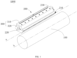
FIG. 1, FIG. 1 is a structural schematic diagram ofcoating equipment 1000 according to an embodiment of this application. Thecoating equipment 1000 provided by the embodiments of this application includes aback roll 100, acoating die head 200, and adetection assembly 300. The coating diehead 200 has acoating opening 210 facing towards theback roll 100, and thecoating opening 210 extends in an axial direction of theback roll 100. Thedetection assembly 300 is configured to detect the position of the coating diehead 200 relative to theback roll 100. - The
back roll 100 may be a rotatable rotary piece in thecoating equipment 1000, a base material is wound on theback roll 100, and theback roll 100 in thecoating equipment 1000 is configured to make the base material run stably. A structure of theback roll 100 may be symmetrical about a central axis of a cylinder, and a material of theback roll 100 may be cast steel, cast iron, and rubber, which will not be limited in the embodiments of this application. - Specifically, the
coating equipment 1000 may be equipment for manufacturing a base material of a battery. Thecoating equipment 1000 may include a control center. The control center may be configured to receive various signals in the operation process of thecoating equipment 1000 and give early warning to a maintainer or control various parts and devices in thecoating equipment 1000 through closed-loop control of an automatic system. - The coating die
head 200 may be a part for coating the base material in thecoating equipment 1000. The coating diehead 200 may be commercially available or customized. The embodiments of this application do not limit the specific model of the coating diehead 200. Thecoating opening 210 is formed at one side, close to theback roll 100, of the coating diehead 200. In the continuously running process of the base material, the coating diehead 200 may continuously spray slurry through thecoating opening 210 to coat the base material. Thecoating opening 210 may be rectangular or circular. "Thecoating opening 210 extends in an axial direction of theback roll 100" means that a length direction of thecoating opening 210 is parallel to a central axis of theback roll 100. - The
detection assembly 300 may be a device in thecoating equipment 1000 for detecting the position change of the coating diehead 200 and theback roll 100. A plurality ofdetection assemblies 300 may be provided. The plurality ofdetection assemblies 300 can improve the accuracy of thedetection assemblies 300 and reduce measurement error. Thedetection assembly 300 may include a detection component, a sensor, and a structural part. - The detection component may detect the position change of the coating die
head 200 and theback roll 100. The detection component may be arange finder 320 and alevel 310. The embodiments of this application do not limit the type of the detection component, as long as the detection component can detect the position change of the die head and theback roll 100. The sensor may send detection and information back to the control center of thecoating equipment 1000. - The structural part may be configured to mount the
detection assembly 300 at other positions of the coating diehead 200 or thecoating equipment 1000. Thedetection assembly 300 may be mounted at any position, as long as thedetection assembly 300 can detect the position change of the coating diehead 200 and theback roll 100. The structural part may be a bracket or a sliding rail. The structural part may make the position of thedetection assembly 300 changeable, thereby not affecting the operation on the coating diehead 200 by a maintainer. In particular, when detecting the gap between the coating diehead 200 and theback roll 100, the position-changeable detection assembly 300 may detect the gap between the coating diehead 200 and theback roll 100 at different positions. - The
detection assembly 300 may detect the position of the coating diehead 200 relative to theback roll 100. It may be understood that many form and position tolerances, such as circular runout, parallelism, and position degree, are set between the coating diehead 200 and theback roll 100. Thedetection assembly 300 may detect all the position changes of the coating diehead 200 and theback roll 100, and feed these position changes back to the control center, so that the position change of the coating diehead 200 and theback roll 100 is within the form and position tolerance, or that is, the position change of the coating diehead 200 and theback roll 100 is within the specification. - In the
coating equipment 1000 provided by the embodiments of this application, thelevel 310 arranged on thedetection assembly 300 can detect the position change of the coating diehead 200 relative to theback roll 100 in real time. - Continuously referring to
FIG. 1 , in some embodiments, thedetection assembly 300 includes alevel 310 mounted on the coating diehead 200. - The
level 310 may be commercially available or customized. The embodiments of this application do not limit the model of thelevel 310. Optionally, thelevel 310 may be mounted on a surface, different from thecoating opening 210, of the coating diehead 200. Thelevel 310 may be fixed on the coating diehead 200 through threaded connection, or may be movably mounted on the coating diehead 200 through a structural part such as a bracket or a sliding rail. When thelevel 310 is movably mounted on the coating diehead 200, thelevel 310 will not affect the operation on the coating diehead 200 by the maintainer and the operation of recording data of thelevel 310. - In this way, the
level 310 may detect the parallelism of the coating diehead 200 relative to theback roll 100. When the parallelism is not within a tolerance range, a maintainer can perform maintenance in time, thereby ensuring the coating stability and ensuring the normal operation of production. - Continuously referring to
FIG. 1 , in some embodiments, thedetection assembly 300 includes arange finder 320. Therange finder 320 is configured to detect a parallelism between a center line a of thecoating opening 210 and a central axis b of theback roll 100. - The
range finder 320 may be commercially available or customized. The embodiments of this application do not limit the model of therange finder 320. Specifically, a plurality ofrange finders 320 may be provided. For example, two, three, four ormore range finders 320 may be provided. The plurality ofrange finders 320 may measure a gap distance of the coating diehead 200 at different positions relative to theback roll 100. Taking the case where thecoating opening 210 is rectangular as an example, the center line a of thecoating opening 210 is a center line of the rectangle parallel to theback roll 100. The parallelism is a maximum allowable error value of parallelism of the central axis b of theback roll 100 relative to the center line a of thecoating opening 210. - In this way, the
range finder 320 may indirectly obtain the parallelism of thecoating equipment 1000 relative to theback roll 100 by detecting the parallelism between the center line of thecoating opening 210 and the central axis of theback roll 100. Compared with a method for detecting the parallelism of other positions, this measuring method has higher accuracy, is simple and convenient to operate, and can reduce the error during measurement and improve the measurement efficiency. - Continuously referring to
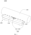
FIG. 1 andFIG. 2, FIG. 2 is a structural schematic diagram ofcoating equipment 1000 according to an embodiment of this application. In some embodiments, therange finder 320 is arranged on the coating diehead 200. Therange finder 320 determines the parallelism by detecting a distance between theback roll 100 and therange finder 320. - Optionally, the
range finder 320 may be mounted on a surface, different from thecoating opening 210, of the coating diehead 200. Therange finder 320 may be fixed on the coating diehead 200 through threaded connection, or may be movably mounted on the coating diehead 200 through a structural part such as a bracket or a sliding rail. When therange finder 320 is movably mounted on the coating diehead 200, therange finder 320 will not affect the operation on the coating diehead 200 by a maintainer and the operation of recording data of therange finder 320. - Taking two
range finders 320 as an example, the tworange finders 320 may be respectively arranged on two sides of the coating diehead 200. The parallelism of the coating diehead 200 relative to theback roll 100 can be obtained by comparing a distance H between theback roll 100 and the coating diehead 200 measured by the tworange finders 320. For example, when a given parallelism tolerance is 2 mm and if the distance H between theback roll 100 and the coating diehead 200 measured by tworange finders 320 is 50 mm and 50.5 mm respectively, it is considered that the parallelism of the coating diehead 200 relative to theback roll 100 is within the specification; and if the distance H between theback roll 100 and the coating diehead 200 measured by tworange finders 320 is 50 mm and 54 mm respectively, it is considered that the parallelism of the coating diehead 200 relative to theback roll 200 exceeds the specification. It should be noted that the above values are only examples for convenient understanding and cannot be regarded as limitations to the embodiments of this application. - In this way, the
range finder 320 may detect the parallelism of the coating diehead 200 relative to theback roll 100. When the parallelism is not within a tolerance range, a maintainer can perform maintenance in time, thereby ensuring the coating stability and ensuring the normal operation of production. - Continuously referring to
FIG. 1 ,FIG. 3 andFIG. 4 ,FIG. 3 is a structural schematic diagram ofcoating equipment 1000 according to an embodiment of this application, andFIG. 4 is a structural schematic diagram ofcoating equipment 1000 according to an embodiment of this application. In some embodiments, therange finder 320 and thelevel 310 are respectively located in different directions of the coating diehead 200. - Exemplarily, the coating die
head 200 may include a front side surface, a rear side surface, a left side surface, a right side surface, an upper side surface, and a lower side surface. The front side surface may be a surface facing theback roll 100, and thecoating opening 210 may be formed on the front side surface. Therange finder 320 and thelevel 310 may be respectively on surfaces, different from the front side surface, in other directions. For example, therange finder 320 may be arranged on the left side surface, and thelevel 310 may be arranged on the upper side surface, which will not be specifically limited by the embodiments of this application. - In this way, the
range finder 320 and thelevel 310 are respectively arranged in different directions of the coating diehead 200, so that interference between therange finder 320 and thelevel 310 can be avoided, and the measurement accuracy can be ensured. - Continuously referring to
FIG. 1 ,FIG. 3 andFIG. 4 , in some embodiments, therange finder 320 is arranged on anend part 220 in a length direction of the coating diehead 200, thelevel 310 is parallel to the length direction of the coating diehead 200, and thelevel 310 is mounted on a surface in the length direction of the coating diehead 200. - Optionally, the case where the coating die
head 200 has a cuboid-like structure is taken as an example. The length direction of the coating diehead 200 is a direction of an edge where a height of the cuboid is located. At this time, therange finder 320 may be arranged in a direction where a top surface and a bottom surface of the cuboid are located, and thelevel 310 may be arranged in a direction where aside surface 230 of the cuboid is located. - In this way, the
range finder 320 is arranged on theend part 220 in the length direction of the coating diehead 200, and thelevel 310 is set to be parallel to the length direction of the coating diehead 200. This design makes the distance between therange finder 320 and thelevel 310 farthest and facilitates the subsequent maintenance of therange finder 320 and thelevel 310, thereby avoiding interference between therange finder 320 and thelevel 310 and ensuring measurement accuracy. - Continuously referring to
FIG. 1 andFIG. 2 , in some embodiments, therange finder 320 is further configured to detect a gap between thecoating opening 210 and theback roll 100. - Specifically, the
range finder 320 may detect the gap between thecoating opening 210 and theback roll 100 through laser ranging, ultrasonic ranging, and infrared ranging. - In this way, the
range finder 320 detects the gap between thecoating opening 210 and theback roll 100. When the gap between theback roll 100 and thecoating opening 210 exceeds the specification, a maintainer can perform maintenance in time, thereby ensuring the coating stability and ensuring the normal operation of production. - Continuously referring to
FIG. 1 andFIG. 2 , in some embodiments, thecoating equipment 1000 includes anadjusting mechanism 400 connected to the coating diehead 200. Theadjusting mechanism 400 is configured to adjust the position of the coating diehead 200. - Specifically, the
adjusting mechanism 400 may be connected to the coating diehead 200 through bolt connection and welding, or may be connected through other manners. For example, a plate connected to the coating diehead 200 may be provided, the plate may be linked with the coating diehead 200, and theadjusting mechanism 400 adjusts the position of the plate so as to adjust the position of the coating diehead 200. - The
adjusting mechanism 400 may adjust the position of the coating diehead 200 relative to theback roll 100. For example, theadjusting mechanism 400 may adjust the gap of the coating diehead 200 relative to theback roll 100. For another example, theadjusting mechanism 400 may adjust the parallelism of the center line of thecoating opening 210 relative to the central axis of theback roll 100. Theadjusting mechanism 400 may adjust the position of the coating diehead 200 through an adjusting bolt, air cylinder driving, and motor driving. - The cavity pressure inside the coating die
head 200 may affect the flow rate of slurry ejected from each area of thecoating opening 210; therefore, theadjusting mechanism 400 may adjust the flow rate of the slurry ejected from each area of thecoating opening 210 by adjusting the cavity pressure inside the coating diehead 200, thereby ensuring the coating stability. It may be understood that when the position of the coating diehead 200 relative to theback roll 100 changes, although the flow rate of the slurry ejected from each area of thecoating opening 210 is different, the position of the coating diehead 200 relative to theback roll 100 in each area is different. For example, the distance between the coating diehead 200 and two ends of a central axis b of theback roll 100 relative to theback roll 100 is different. Therefore, the spraying weight on the base material may be consistent, that is, the coating stability is ensured. - In this way, when the
detection assembly 300 detects that the position of the coating diehead 200 relative to theback roll 100 exceeds the specification, theadjusting mechanism 400 may be configured to adjust the position of the coating diehead 200, so that the position of the coating diehead 200 relative to theback roll 100 returns to the specification, thereby ensuring the coating stability and ensuring the normal operation of production. - Continuously referring to
FIG. 1 andFIG. 2 , in some embodiments, thecoating equipment 1000 includes amachine frame 500 and abearing plate 600, the coating diehead 200 is mounted on thebearing plate 600, theadjusting mechanism 400 is mounted on themachine frame 500 and is connected to thebearing plate 600, and theadjusting mechanism 400 adjusts the degree of freedom of thebearing plate 600 in at least one direction to adjust the degree of freedom of the coating diehead 200. - Specifically, the
machine frame 500 is a main structural part of the coating diehead 200, and the position of themachine frame 500 relative to the coating diehead 200 is fixed. The coating diehead 200 may be mounted on thebearing plate 600 through bolt connection and clamping connection. Theadjusting mechanism 400 may be mounted on themachine frame 500 through bolt connection and clamping connection, and is connected to thebearing plate 600 through bolt connection and welding. Theadjusting mechanism 400 may adjust the degree of freedom of thebearing plate 600 in an up-down direction, a left-right direction, and a front-back direction, so that when the gap or the parallelism of the coating diehead 200 relative to theback roll 100 changes, a maintainer may adjust the gap or the parallelism to be within the specification by theadjusting mechanism 400, or may adjust the gap or the parallelism to be within the specification by a closed-loop automatic system. - In this way, compared with the method of directly mounting the
adjusting mechanism 400 on the coating diehead 200, theadjusting mechanism 400 is arranged on thebearing plate 600 and can adjust the degree of freedom of the coating diehead 200 without changing the original structure of the coating diehead 200. - Continuously referring to
FIG. 1 andFIG. 2 , in some embodiments, theadjusting mechanism 400 includes at least one of a threadedpiece 410 and anautomatic control system 420 that are connected to thebearing plate 600. - Specifically, the bearing
plate 600 may be provided with a plurality of screw holes, and a plurality of threadedpieces 410 may be arranged in the screw holes. When thedetection assembly 300 detects that a size such as the gap or the parallelism of the coating diehead 200 relative to theback roll 100 exceeds the specification, on one hand, thedetection assembly 300 can warn a maintainer in time, and the maintainer can adjust the size such as the gap or the parallelism of the coating diehead 200 relative to theback roll 100 to be within the specification by adjusting the threadedpieces 410; and on the other hand, thedetection assembly 300 can send detection information back to a control center, the control center sends an instruction to control theautomatic control system 420 to drive theadjusting mechanism 400 to adjust the size such as the gap or the parallelism of the coating diehead 200 relative to theback roll 100 to be within the specification. For example, theadjusting mechanism 400 may include a mechanical arm. After theautomatic control system 420 receives the instruction, theautomatic control system 420 may drive the mechanical arm to drive the bearingplate 600, so that the coating diehead 200 mounted on thebearing plate 600 is linked, and the position of the coating diehead 200 relative to theback roll 100 changes according to instruction information, thereby ensuring that the gap and the parallelism of the coating diehead 200 relative to theback roll 100 are within the specification. - In this way, the threaded
piece 410 may be adjusted manually and conveniently, and the manufacturing cost is low. Theautomatic control system 420 may adjust the position of the coating diehead 200 in real time. Theautomatic control system 420 is more efficient and can ensure the normal operation of production to the greatest extent. - Continuously referring to
FIG. 1 andFIG. 2 , in one specific embodiment,coating equipment 1000 is provided. Thecoating equipment 1000 provided by the embodiments of this application includes aback roll 100, acoating die head 200, and adetection assembly 300. Thedetection assembly 300 may be mounted at a position where the gap and the parallelism of the coating diehead 200 relative to theback roll 100 can be detected conveniently, and theadjusting mechanism 400 is arranged at the periphery of the coating diehead 200, so that the position of the coating diehead 200 relative to theback roll 100 can be adjusted, thereby solving the problem of poor coating stability caused by the fact that the gap and the parallelism of the coating diehead 200 relative to theback roll 100 exceed the specification. - Finally, it should be noted that the foregoing embodiments are merely intended for describing the technical solutions of this application, but not for limiting this application. Although this application is described in detail with reference to the foregoing embodiments, those of ordinary skill in the art should understand that they may still make modifications to the technical solutions described in the foregoing embodiments or make equivalent replacements to some or all technical features thereof; and these modifications or replacements do not make the essence of the corresponding technical solution depart from the scope of the technical solutions of the embodiments of this application, and should fall within the scope of claims and specification of this application. In particular, as long as there is no structural conflict, the technical features in the embodiments can be combined in any way. This application is not limited to the specific embodiments disclosed herein, but includes all technical solutions falling within the scope of the claims.
Claims (10)
- Coating equipment, characterized in that the equipment comprises:a back roll;a coating die head, having a coating opening facing towards the back roll, the coating opening extending in an axial direction of the back roll; anda detection assembly, configured to detect a position of the coating die head relative to the back roll and comprising a level mounted on the coating die head.
- The coating equipment according to claim 1, characterized in that the detection assembly comprises a range finder, and the range finder is configured to detect a parallelism between a center line of the coating opening and a central axis of the back roll.
- The coating equipment according to claim 2, characterized in that the range finder is arranged on the coating die head, and the range finder determines the parallelism by detecting a distance between the back roll and the range finder.
- The coating equipment according to claim 3, characterized in that the range finder and the level are respectively located in different directions of the coating die head.
- The coating equipment according to claim 3, characterized in that the range finder is arranged on an end part in a length direction of the coating die head, the level is parallel to the length direction of the coating die head, and the level is mounted on a surface in the length direction of the coating die head.
- The coating equipment according to claim 2, characterized in that the range finder is further configured to detect a gap between the coating opening and the back roll.
- The coating equipment according to claim 1, characterized in that the coating equipment comprises an adjusting mechanism connected to the coating die head, and the adjusting mechanism is configured to adjust the position of the coating die head.
- The coating equipment according to claim 7, characterized in that the coating equipment comprises a machine frame and a bearing plate, the coating die head is mounted on the bearing plate, the adjusting mechanism is mounted on the machine frame and is connected to the bearing plate, and the adjusting mechanism adjusts a degree of freedom in at least one direction of the bearing plate to adjust a degree of freedom of the coating die head.
- The coating equipment according to claim 8, characterized in that the adjusting mechanism comprises at least one of a threaded piece and an automatic control system that are connected to the bearing plate.
- The coating equipment according to claim 7, characterized in that the adjusting mechanism is configured to adjust the gap between the coating die head and the back roll.
Applications Claiming Priority (2)
| Application Number | Priority Date | Filing Date | Title |
|---|---|---|---|
| CN202223079806.3U CN218517085U (en) | 2022-11-21 | 2022-11-21 | Coating apparatus |
| PCT/CN2023/070528 WO2024108741A1 (en) | 2022-11-21 | 2023-01-04 | Coating apparatus |
Publications (3)
| Publication Number | Publication Date |
|---|---|
| EP4397416A1 true EP4397416A1 (en) | 2024-07-10 |
| EP4397416A4 EP4397416A4 (en) | 2024-10-02 |
| EP4397416B1 EP4397416B1 (en) | 2026-03-25 |
Family
ID=91081297
Family Applications (1)
| Application Number | Title | Priority Date | Filing Date |
|---|---|---|---|
| EP23754100.8A Active EP4397416B1 (en) | 2022-11-21 | 2023-01-04 | Coating apparatus |
Country Status (2)
| Country | Link |
|---|---|
| US (1) | US20240165655A1 (en) |
| EP (1) | EP4397416B1 (en) |
Families Citing this family (1)
| Publication number | Priority date | Publication date | Assignee | Title |
|---|---|---|---|---|
| CN218945476U (en) * | 2022-11-29 | 2023-05-02 | 宁德时代新能源科技股份有限公司 | Coating dies and coating equipment |
Family Cites Families (2)
| Publication number | Priority date | Publication date | Assignee | Title |
|---|---|---|---|---|
| CN206731444U (en) * | 2017-04-21 | 2017-12-12 | 宁德嘉拓智能设备有限公司 | A kind of lithium battery coating machine die head fine position device |
| CN215141487U (en) * | 2021-04-27 | 2021-12-14 | 深圳市曼恩斯特科技股份有限公司 | Coating gap real-time adjusting device |
-
2023
- 2023-01-04 EP EP23754100.8A patent/EP4397416B1/en active Active
- 2023-10-27 US US18/384,382 patent/US20240165655A1/en active Pending
Also Published As
| Publication number | Publication date |
|---|---|
| EP4397416A4 (en) | 2024-10-02 |
| US20240165655A1 (en) | 2024-05-23 |
| EP4397416B1 (en) | 2026-03-25 |
Similar Documents
| Publication | Publication Date | Title |
|---|---|---|
| EP4397416A1 (en) | Coating apparatus | |
| US20150153159A1 (en) | Testing device | |
| WO2024108741A1 (en) | Coating apparatus | |
| CN210139227U (en) | a turning mechanism | |
| CN221223704U (en) | Parallelism detecting device | |
| CN116728156B (en) | An Automatic Centering Method for Bilateral Steel Shearing Plates Based on Laser Ranging | |
| CN211042138U (en) | A connecting rod detection device | |
| US11709045B1 (en) | Surface texture probe and measurement apparatus with a vibrational membrane | |
| US20240017363A1 (en) | Cutter bending angle detection device, cutter bending machine, and cutter bending angle detection method | |
| CN116653411B (en) | Paper deviation correcting device and deviation correcting method for printing process | |
| CN215865091U (en) | Jumping detection device for columnar metal piece | |
| CN211616627U (en) | 3D printer | |
| CN219024864U (en) | Coating apparatus | |
| CN216283139U (en) | Detection device for printed matter size | |
| CN117685858A (en) | Verticality detection device | |
| CN219016609U (en) | In place detection mechanism and battery processing equipment | |
| CN223071829U (en) | Mounting structure of injection molding machine moving die electronic ruler | |
| CN222505390U (en) | A fixture for detecting the flatness of assembly surfaces of multi-surface assembly workpieces | |
| CN208818231U (en) | A kind of heavy load optical angle adjustment frame | |
| CN220033563U (en) | Tension balancing device for accurately detecting two ends of composite paper | |
| CN223960910U (en) | Quick positioning drilling tool | |
| CN215572745U (en) | Mould molding profile self-checking mechanism | |
| CN218628128U (en) | Vehicle detection device and production line body | |
| CN223408872U (en) | Label feed bin device of size self-adaptation | |
| CN221174369U (en) | Calibration device and burr detection equipment |
Legal Events
| Date | Code | Title | Description |
|---|---|---|---|
| STAA | Information on the status of an ep patent application or granted ep patent |
Free format text: STATUS: UNKNOWN |
|
| STAA | Information on the status of an ep patent application or granted ep patent |
Free format text: STATUS: THE INTERNATIONAL PUBLICATION HAS BEEN MADE |
|
| PUAI | Public reference made under article 153(3) epc to a published international application that has entered the european phase |
Free format text: ORIGINAL CODE: 0009012 |
|
| STAA | Information on the status of an ep patent application or granted ep patent |
Free format text: STATUS: REQUEST FOR EXAMINATION WAS MADE |
|
| 17P | Request for examination filed |
Effective date: 20230822 |
|
| AK | Designated contracting states |
Kind code of ref document: A1 Designated state(s): AL AT BE BG CH CY CZ DE DK EE ES FI FR GB GR HR HU IE IS IT LI LT LU LV MC ME MK MT NL NO PL PT RO RS SE SI SK SM TR |
|
| A4 | Supplementary search report drawn up and despatched |
Effective date: 20240829 |
|
| RAP1 | Party data changed (applicant data changed or rights of an application transferred) |
Owner name: CONTEMPORARY AMPEREX TECHNOLOGY(HONG KONG) LIMITED |
|
| RIC1 | Information provided on ipc code assigned before grant |
Ipc: B05C 11/10 20060101ALN20240823BHEP Ipc: H01M 4/04 20060101ALN20240823BHEP Ipc: B05C 13/02 20060101ALI20240823BHEP Ipc: B05C 5/02 20060101AFI20240823BHEP |
|
| STAA | Information on the status of an ep patent application or granted ep patent |
Free format text: STATUS: EXAMINATION IS IN PROGRESS |
|
| 17Q | First examination report despatched |
Effective date: 20250624 |
|
| GRAP | Despatch of communication of intention to grant a patent |
Free format text: ORIGINAL CODE: EPIDOSNIGR1 |
|
| STAA | Information on the status of an ep patent application or granted ep patent |
Free format text: STATUS: GRANT OF PATENT IS INTENDED |
|
| RIC1 | Information provided on ipc code assigned before grant |
Ipc: B05C 5/02 20060101AFI20251028BHEP Ipc: B05C 13/02 20060101ALI20251028BHEP Ipc: H01M 4/04 20060101ALN20251028BHEP Ipc: B05C 11/10 20060101ALN20251028BHEP |
|
| DAV | Request for validation of the european patent (deleted) | ||
| DAX | Request for extension of the european patent (deleted) | ||
| INTG | Intention to grant announced |
Effective date: 20251118 |
|
| GRAS | Grant fee paid |
Free format text: ORIGINAL CODE: EPIDOSNIGR3 |
|
| GRAA | (expected) grant |
Free format text: ORIGINAL CODE: 0009210 |
|
| STAA | Information on the status of an ep patent application or granted ep patent |
Free format text: STATUS: THE PATENT HAS BEEN GRANTED |
|
| AK | Designated contracting states |
Kind code of ref document: B1 Designated state(s): AL AT BE BG CH CY CZ DE DK EE ES FI FR GB GR HR HU IE IS IT LI LT LU LV MC ME MK MT NL NO PL PT RO RS SE SI SK SM TR |
|
| REG | Reference to a national code |
Ref country code: CH Ref legal event code: F10 Free format text: ST27 STATUS EVENT CODE: U-0-0-F10-F00 (AS PROVIDED BY THE NATIONAL OFFICE) Effective date: 20260325 Ref country code: GB Ref legal event code: FG4D |
|
| REG | Reference to a national code |
Ref country code: DE Ref legal event code: R096 Ref document number: 602023014176 Country of ref document: DE |
|
| REG | Reference to a national code |
Ref country code: IE Ref legal event code: FG4D |