EP4397266A1 - System for optic-based ablation zone simulation - Google Patents
System for optic-based ablation zone simulation Download PDFInfo
- Publication number
- EP4397266A1 EP4397266A1 EP24150507.2A EP24150507A EP4397266A1 EP 4397266 A1 EP4397266 A1 EP 4397266A1 EP 24150507 A EP24150507 A EP 24150507A EP 4397266 A1 EP4397266 A1 EP 4397266A1
- Authority
- EP
- European Patent Office
- Prior art keywords
- ablation
- display
- target
- computing device
- patient
- Prior art date
- Legal status (The legal status is an assumption and is not a legal conclusion. Google has not performed a legal analysis and makes no representation as to the accuracy of the status listed.)
- Granted
Links
Images


Classifications
-
- A—HUMAN NECESSITIES
- A61—MEDICAL OR VETERINARY SCIENCE; HYGIENE
- A61B—DIAGNOSIS; SURGERY; IDENTIFICATION
- A61B18/00—Surgical instruments, devices or methods for transferring non-mechanical forms of energy to or from the body
- A61B18/18—Surgical instruments, devices or methods for transferring non-mechanical forms of energy to or from the body by applying electromagnetic radiation, e.g. microwaves
- A61B18/1815—Surgical instruments, devices or methods for transferring non-mechanical forms of energy to or from the body by applying electromagnetic radiation, e.g. microwaves using microwaves
-
- G—PHYSICS
- G16—INFORMATION AND COMMUNICATION TECHNOLOGY [ICT] SPECIALLY ADAPTED FOR SPECIFIC APPLICATION FIELDS
- G16H—HEALTHCARE INFORMATICS, i.e. INFORMATION AND COMMUNICATION TECHNOLOGY [ICT] SPECIALLY ADAPTED FOR THE HANDLING OR PROCESSING OF MEDICAL OR HEALTHCARE DATA
- G16H40/00—ICT specially adapted for the management or administration of healthcare resources or facilities; ICT specially adapted for the management or operation of medical equipment or devices
- G16H40/60—ICT specially adapted for the management or administration of healthcare resources or facilities; ICT specially adapted for the management or operation of medical equipment or devices for the operation of medical equipment or devices
- G16H40/63—ICT specially adapted for the management or administration of healthcare resources or facilities; ICT specially adapted for the management or operation of medical equipment or devices for the operation of medical equipment or devices for local operation
-
- A—HUMAN NECESSITIES
- A61—MEDICAL OR VETERINARY SCIENCE; HYGIENE
- A61B—DIAGNOSIS; SURGERY; IDENTIFICATION
- A61B17/00—Surgical instruments, devices or methods
- A61B2017/00017—Electrical control of surgical instruments
- A61B2017/00022—Sensing or detecting at the treatment site
- A61B2017/00057—Light
- A61B2017/00061—Light spectrum
-
- A—HUMAN NECESSITIES
- A61—MEDICAL OR VETERINARY SCIENCE; HYGIENE
- A61B—DIAGNOSIS; SURGERY; IDENTIFICATION
- A61B17/00—Surgical instruments, devices or methods
- A61B2017/00017—Electrical control of surgical instruments
- A61B2017/00199—Electrical control of surgical instruments with a console, e.g. a control panel with a display
-
- A—HUMAN NECESSITIES
- A61—MEDICAL OR VETERINARY SCIENCE; HYGIENE
- A61B—DIAGNOSIS; SURGERY; IDENTIFICATION
- A61B18/00—Surgical instruments, devices or methods for transferring non-mechanical forms of energy to or from the body
- A61B2018/00005—Cooling or heating of the probe or tissue immediately surrounding the probe
- A61B2018/00011—Cooling or heating of the probe or tissue immediately surrounding the probe with fluids
- A61B2018/00023—Cooling or heating of the probe or tissue immediately surrounding the probe with fluids closed, i.e. without wound contact by the fluid
-
- A—HUMAN NECESSITIES
- A61—MEDICAL OR VETERINARY SCIENCE; HYGIENE
- A61B—DIAGNOSIS; SURGERY; IDENTIFICATION
- A61B18/00—Surgical instruments, devices or methods for transferring non-mechanical forms of energy to or from the body
- A61B2018/00571—Surgical instruments, devices or methods for transferring non-mechanical forms of energy to or from the body for achieving a particular surgical effect
- A61B2018/00577—Ablation
-
- A—HUMAN NECESSITIES
- A61—MEDICAL OR VETERINARY SCIENCE; HYGIENE
- A61B—DIAGNOSIS; SURGERY; IDENTIFICATION
- A61B18/00—Surgical instruments, devices or methods for transferring non-mechanical forms of energy to or from the body
- A61B2018/00636—Sensing and controlling the application of energy
- A61B2018/00642—Sensing and controlling the application of energy with feedback, i.e. closed loop control
-
- A—HUMAN NECESSITIES
- A61—MEDICAL OR VETERINARY SCIENCE; HYGIENE
- A61B—DIAGNOSIS; SURGERY; IDENTIFICATION
- A61B18/00—Surgical instruments, devices or methods for transferring non-mechanical forms of energy to or from the body
- A61B2018/00636—Sensing and controlling the application of energy
- A61B2018/0066—Sensing and controlling the application of energy without feedback, i.e. open loop control
-
- A—HUMAN NECESSITIES
- A61—MEDICAL OR VETERINARY SCIENCE; HYGIENE
- A61B—DIAGNOSIS; SURGERY; IDENTIFICATION
- A61B18/00—Surgical instruments, devices or methods for transferring non-mechanical forms of energy to or from the body
- A61B2018/00636—Sensing and controlling the application of energy
- A61B2018/00696—Controlled or regulated parameters
- A61B2018/00702—Power or energy
-
- A—HUMAN NECESSITIES
- A61—MEDICAL OR VETERINARY SCIENCE; HYGIENE
- A61B—DIAGNOSIS; SURGERY; IDENTIFICATION
- A61B18/00—Surgical instruments, devices or methods for transferring non-mechanical forms of energy to or from the body
- A61B2018/00636—Sensing and controlling the application of energy
- A61B2018/00773—Sensed parameters
- A61B2018/00779—Power or energy
- A61B2018/00785—Reflected power
-
- A—HUMAN NECESSITIES
- A61—MEDICAL OR VETERINARY SCIENCE; HYGIENE
- A61B—DIAGNOSIS; SURGERY; IDENTIFICATION
- A61B18/00—Surgical instruments, devices or methods for transferring non-mechanical forms of energy to or from the body
- A61B2018/00636—Sensing and controlling the application of energy
- A61B2018/00773—Sensed parameters
- A61B2018/00791—Temperature
- A61B2018/00797—Temperature measured by multiple temperature sensors
-
- A—HUMAN NECESSITIES
- A61—MEDICAL OR VETERINARY SCIENCE; HYGIENE
- A61B—DIAGNOSIS; SURGERY; IDENTIFICATION
- A61B18/00—Surgical instruments, devices or methods for transferring non-mechanical forms of energy to or from the body
- A61B18/18—Surgical instruments, devices or methods for transferring non-mechanical forms of energy to or from the body by applying electromagnetic radiation, e.g. microwaves
- A61B18/1815—Surgical instruments, devices or methods for transferring non-mechanical forms of energy to or from the body by applying electromagnetic radiation, e.g. microwaves using microwaves
- A61B2018/1861—Surgical instruments, devices or methods for transferring non-mechanical forms of energy to or from the body by applying electromagnetic radiation, e.g. microwaves using microwaves with an instrument inserted into a body lumen or cavity, e.g. a catheter
-
- A—HUMAN NECESSITIES
- A61—MEDICAL OR VETERINARY SCIENCE; HYGIENE
- A61B—DIAGNOSIS; SURGERY; IDENTIFICATION
- A61B18/00—Surgical instruments, devices or methods for transferring non-mechanical forms of energy to or from the body
- A61B18/18—Surgical instruments, devices or methods for transferring non-mechanical forms of energy to or from the body by applying electromagnetic radiation, e.g. microwaves
- A61B18/1815—Surgical instruments, devices or methods for transferring non-mechanical forms of energy to or from the body by applying electromagnetic radiation, e.g. microwaves using microwaves
- A61B2018/1869—Surgical instruments, devices or methods for transferring non-mechanical forms of energy to or from the body by applying electromagnetic radiation, e.g. microwaves using microwaves with an instrument interstitially inserted into the body, e.g. needles
Definitions
- the present disclosure relates to systems, methods, and devices for simulating ablation zones in a microwave ablation treatment procedure using optic-based temperature measurements.
- clinicians When planning a treatment procedure, clinicians often rely on patient data including X-ray data, computed tomography (CT) scan data, magnetic resonance imaging (MRI) data, or other imaging data that allows the clinician to view the internal anatomy of a patient.
- CT computed tomography
- MRI magnetic resonance imaging
- the clinician utilizes the patient data to identify targets of interest and to develop strategies for accessing the targets of interest for a treatment procedure such as a microwave ablation treatment procedure.
- Imaging modalities introduce unique challenges when monitoring the progression of an ablation zone during an ablation procedure.
- Ultrasound imaging displays "bubbles” or ground glass opacity as energy is delivered, making it difficult to determine the edge of the actual ablation zone during progression of the application of energy.
- CT imaging provides "near-time” imaging that reflects the ablation zone size at the time that the last scan was captured, however, does not reflect ablation growth as it occurs in real time.
- predicting the expected final ablation zone characteristics e.g., dimensions, shape, etc. upon completion of the application of energy
- the progression of the actual ablation characteristics toward the final ablation zone characteristics is difficult as one standard data set used to predict the final ablation zone characteristics may not be generic to multiple patients and/or multiple targets and the clinician is unable to visualize the actual progression of the ablation zone in real time relative to the final ablation zone characteristics.
- an ablation system includes an ablation device and a computing device.
- the ablation device includes a radiating antenna configured to apply microwave ablation energy to a target within a patient to ablate the target and a fiber including Bragg gratings formed along a length thereof and configured to reflect light therefrom.
- the computing device includes a processor and memory storing instructions which, when executed by the processor, cause the computing device to calculate temperature measurements based on the reflected light during application of microwave ablation energy to the target and extrapolate the temperature measurements calculated to generate an ablation volume in real time.
- the system may further include a display operably coupled to the computing device and the computing device may be configured to cause the display to display a progression of the ablation volume in real time. Additionally, or alternatively, the computing device may be configured to cause the display to overlay the ablation volume onto an image of the target within the patient. Additionally, or alternatively, the computing device may be configured to calculate a total expected ablation zone, cause the display to display the total expected ablation zone onto an image of the target within the patient, and cause the display to display the progression of the ablation volume within the display of the total expected ablation zone.
- the ablation device may be a flexible microwave ablation catheter configured to be navigated to the target through a patient's luminal network.
- the computing device may be configured to determine an expected ablation zone geometry to be formed by the ablation device based on a model of the ablation device, and extrapolate the temperature measurements based on the expected ablation zone geometry determined.
- the expected ablation zone geometry may be substantially spherically shaped and the computing device may be configured to extrapolate the temperature measurements based on the substantially spherical shape.
- the image of the target may be a three dimensional rendering of a portion of the patient generated from at least one of DICOM images or fluoroscopic images.
- the computing device may be configured to calculate a total expected ablation zone, cause the display to display the total expected ablation zone onto an image of the target within the patient, and cause the display to display the progression of the ablation volume within the display of the total expected ablation zone.
- catheter 12 is part of a catheter guide assembly 40.
- the catheter 12 is inserted into bronchoscope 30 for access to a luminal network of patient "P.”
- catheter 12 of catheter guide assembly 40 may be inserted into a working channel of bronchoscope 30 for navigation through a patient's luminal network.
- a distal portion of the catheter 12 includes a sensor 44. The position and orientation of the sensor 44 relative to the reference coordinate system, and thus the distal portion of the catheter 12, within an electromagnetic field can be derived.
- EMN system 10 generally includes an operating table 20 configured to support a patient "P;” a bronchoscope 30 configured for insertion through patient's "P's” mouth into patient's "P's” airways; monitoring equipment 120 coupled to bronchoscope 30 (e.g., a video display, for displaying the video images received from the video imaging system of bronchoscope 30); a tracking system 50 including a tracking module 52, a plurality of reference sensors 54 and a transmitter mat 56; and a computing device 100 including software and/or hardware used to facilitate identification of a target, pathway planning to the target, navigation of a medical instrument to the target, and confirmation of placement of an catheter 12, or a suitable device therethrough, relative to the target.
- monitoring equipment 120 coupled to bronchoscope 30 (e.g., a video display, for displaying the video images received from the video imaging system of bronchoscope 30); a tracking system 50 including a tracking module 52, a plurality of reference sensors 54 and a transmitter mat 56; and a computing device 100
- a fluoroscopic imaging device 110 capable of acquiring fluoroscopic or x-ray images or video of patient "P" is also included in this particular aspect of system 10.
- the fluoroscopic data e.g., images, series of images, or video
- the fluoroscopic imaging device 110 may be stored within the fluoroscopic imaging device 110 or transmitted to computing device 100 for storage, processing, and display. Additionally, the fluoroscopic imaging device 110 may move relative to patient "P" so that images may be acquired from different angles or perspectives relative to patient "P” to create a fluoroscopic video from a fluoroscopic sweep.
- the pose of fluoroscopic imaging device 110 relative to patient "P" and while capturing the images may be estimated via markers incorporated with the transmitter mat 56.
- the markers are positioned under patient "P", between patient “P” and operating table 20 and between patient “P” and a radiation source or a sensing unit of fluoroscopic imaging device 110.
- the markers incorporated with the transmitter mat 56 may be two separate elements which may be coupled in a fixed manner or alternatively may be manufactured as a single unit.
- Fluoroscopic imaging device 110 may include a single imaging device or more than one imaging device. In embodiments including multiple imaging devices, each imaging device may be a different type of imaging device or the same type.
- Computing device 100 may be any suitable computing device including a processor and storage medium, wherein the processor is capable of executing instructions stored on the storage medium.
- the computing device 100 may further include a database configured to store patient data, CT data sets including CT images, fluoroscopic data sets including fluoroscopic images and video, navigation plans, and any other such data.
- the computing device 100 may include inputs, or may otherwise be configured to receive, CT data sets, fluoroscopic images/video and other data described herein.
- computing device 100 includes a display (e.g., display 206) configured to display graphical user interfaces.
- computing device 100 utilizes previously acquired CT image data for generating and viewing a three-dimensional model or rendering of patient "P's” airways, enables the identification of a target on the three-dimensional model (automatically, semiautomatically, or manually), and allows for determining a pathway through patient "P's” airways to tissue located at and around the target. More specifically, CT images acquired from previous CT scans are processed and assembled into a three-dimensional CT volume, which is then utilized to generate a three-dimensional model of patient "P's” airways. The three-dimensional model may be displayed on a display 206 associated with computing device 100, or in any other suitable fashion.
- the enhanced two-dimensional images may possess some three-dimensional capabilities because they are generated from three-dimensional data.
- the three-dimensional model may be manipulated to facilitate identification of target on the three-dimensional model or two-dimensional images, and selection of a suitable pathway through patient "P's" airways to access tissue located at the target can be made. Once selected, the pathway plan, three-dimensional model, and images derived therefrom, can be saved and exported to a navigation system for use during the navigation phase(s).
- One such planning software is the ILLUMISITE ® planning suite currently sold by Medtronic plc.
- Tracking system 50 includes a tracking module 52, a plurality of reference sensors 54, and a transmitter mat 56 (including markers if applicable). Tracking system 50 is configured for use with a sensor 44 of catheter guide assembly 40 to track the electromagnetic position thereof within an electromagnetic coordinate system.
- Transmitter mat 56 is positioned beneath patient "P." Transmitter mat 56 generates an electromagnetic field around at least a portion of patient "P" within which the position of a plurality of reference sensors 54 and the sensor 44 can be determined with use of a tracking module 52.
- a second electromagnetic sensor 126 may also be incorporated into the end of the catheter 12. The second electromagnetic sensor 126 may be a five degree-of-freedom sensor or a six degree-of-freedom sensor.
- One or more of reference sensors 54 are attached to the chest of patient "P.” The six degrees of freedom coordinates of reference sensors 54 are sent to computing device 100 (which includes the appropriate software) where they are used to calculate a patient coordinate frame of reference.
- Registration is generally performed to coordinate locations of the three dimensional model and two dimensional images from the planning phase with patient's "P's" airways as observed through the bronchoscope 30, and allow for the navigation phase to be undertaken with precise knowledge of the location of the sensor 44, even in portions of the airway where the bronchoscope 30 cannot reach.
- a user interface is displayed in the navigation software which sets forth the pathway that the clinician is to follow to reach the target.
- the ablation device 130 includes a fiber 300 which may be coupled to the outer jacket 132.
- the fiber 300 is embedded into the outer jacket 132.
- the fiber 300 may be positioned in the lumen 132a of the outer jacket 132 or on an outer surface of the outer jacket 132.
- the fiber 300 may be retrofitted to an ablation device 130 by securing the fiber 300 to the outer jacket 132 via heat-shrink or other mediums.
Landscapes
- Health & Medical Sciences (AREA)
- Engineering & Computer Science (AREA)
- Biomedical Technology (AREA)
- Life Sciences & Earth Sciences (AREA)
- Surgery (AREA)
- Public Health (AREA)
- General Health & Medical Sciences (AREA)
- Medical Informatics (AREA)
- Physics & Mathematics (AREA)
- Electromagnetism (AREA)
- Nuclear Medicine, Radiotherapy & Molecular Imaging (AREA)
- Otolaryngology (AREA)
- Heart & Thoracic Surgery (AREA)
- Molecular Biology (AREA)
- Animal Behavior & Ethology (AREA)
- Veterinary Medicine (AREA)
- Primary Health Care (AREA)
- Epidemiology (AREA)
- General Business, Economics & Management (AREA)
- Business, Economics & Management (AREA)
- Surgical Instruments (AREA)
Abstract
Description
- This application claims the benefit of the filing date of provisional
U.S. Patent Application No. 63/437,417, filed on January 6, 2023 - The present disclosure relates to systems, methods, and devices for simulating ablation zones in a microwave ablation treatment procedure using optic-based temperature measurements.
- When planning a treatment procedure, clinicians often rely on patient data including X-ray data, computed tomography (CT) scan data, magnetic resonance imaging (MRI) data, or other imaging data that allows the clinician to view the internal anatomy of a patient. The clinician utilizes the patient data to identify targets of interest and to develop strategies for accessing the targets of interest for a treatment procedure such as a microwave ablation treatment procedure.
- Microwave antennas generate heat in the body to provide hyperthermic temperatures to destroy tissues of interest. A challenge with radiated fields that are emitted from a highfrequency antenna is that it is difficult to measure the temperature profile induced in the tissue resulting from exposure to the radiated field, thus complicating the ability to determine the zone of ablation during the application of energy to the tissue.
- Existing imaging modalities introduce unique challenges when monitoring the progression of an ablation zone during an ablation procedure. Ultrasound imaging displays "bubbles" or ground glass opacity as energy is delivered, making it difficult to determine the edge of the actual ablation zone during progression of the application of energy. CT imaging provides "near-time" imaging that reflects the ablation zone size at the time that the last scan was captured, however, does not reflect ablation growth as it occurs in real time.
- Additionally, predicting the expected final ablation zone characteristics (e.g., dimensions, shape, etc. upon completion of the application of energy) and the progression of the actual ablation characteristics toward the final ablation zone characteristics is difficult as one standard data set used to predict the final ablation zone characteristics may not be generic to multiple patients and/or multiple targets and the clinician is unable to visualize the actual progression of the ablation zone in real time relative to the final ablation zone characteristics.
- Systems and methods for simulating ablation zones in a microwave ablation treatment procedure using optic-based temperature measurements are provided.
- According to an aspect of the present disclosure, an ablation system includes an ablation device and a computing device. The ablation device includes a radiating antenna configured to apply microwave ablation energy to a target within a patient to ablate the target and a fiber including Bragg gratings formed along a length thereof and configured to reflect light therefrom. The computing device includes a processor and memory storing instructions which, when executed by the processor, cause the computing device to calculate temperature measurements based on the reflected light during application of microwave ablation energy to the target and extrapolate the temperature measurements calculated to generate an ablation volume in real time.
- In an aspect, the system may further include a display operably coupled to the computing device and the computing device may be configured to cause the display to display a progression of the ablation volume in real time. Additionally, or alternatively, the computing device may be configured to cause the display to overlay the ablation volume onto an image of the target within the patient. Additionally, or alternatively, the computing device may be configured to calculate a total expected ablation zone, cause the display to display the total expected ablation zone onto an image of the target within the patient, and cause the display to display the progression of the ablation volume within the display of the total expected ablation zone.
- In an aspect, the Bragg gratings may be etched into the fiber.
- In an aspect, the ablation device may be a flexible microwave ablation catheter configured to be navigated to the target through a patient's luminal network.
- In an aspect, the ablation device may be a rigid microwave ablation device configured to be percutaneously inserted through tissue to access the target.
- In an aspect, the computing device may be configured to generate the ablation volume based on the extrapolated temperature measurements, a total amount of microwave ablation energy applied, and a duration of energy application.
- In an aspect, the computing device may be configured to determine an expected ablation zone geometry to be formed by the ablation device based on a model of the ablation device, and extrapolate the temperature measurements based on the expected ablation zone geometry determined. Additionally, or alternatively, the expected ablation zone geometry may be substantially spherically shaped and the computing device may be configured to extrapolate the temperature measurements based on the substantially spherical shape.
- In accordance with another aspect of the disclosure, an ablation system includes a computing device. The computing device includes a processor and memory storing instructions which, when executed by the processor, cause the computing device to receive reflected light from fiber Bragg gratings of an ablation device, calculate temperature measurements based on the reflected light during application of microwave ablation energy by the ablation device to a target within a patient, and extrapolate the temperature measurements calculated to generate an ablation volume in real time. Additionally, the computing device is configured to cause a display device to display an image of the target, and cause the display device to overlay a progression of the ablation volume onto the image of the target.
- In an aspect, the image of the target may be a three dimensional rendering of a portion of the patient generated from at least one of DICOM images or fluoroscopic images.
- In an aspect, the computing device may be configured to calculate a total expected ablation zone, cause the display to display the total expected ablation zone onto an image of the target within the patient, and cause the display to display the progression of the ablation volume within the display of the total expected ablation zone.
- In an aspect, the computing device may be configured to generate the ablation volume based on the extrapolated temperature measurements, a total amount of microwave ablation energy applied, and a duration of energy application.
- In accordance with another aspect of the disclosure, a method for optic-based ablation zone simulation includes receiving reflected light from fiber Bragg gratings of an ablation device, calculating temperature measurements based on the reflected light during application of microwave ablation energy by the ablation device to a target within a patient, and extrapolating the temperature measurements calculated to generate an ablation volume in real time. The method further includes causing a display device to display an image of the target, and causing the display device to overlay a progression of the ablation volume onto the image of the target.
- In an aspect, causing the display device to display the image of the target includes causing the display device to display a three dimensional rendering of a portion of the patient generated from at least one of DICOM images or fluoroscopic images.
- In an aspect, the method may further include calculating a total expected ablation zone based on one or more of a type of ablation device, a total power setting, and a total duration of application of microwave energy. Additionally, or alternatively, the method may further include causing the display to display the total expected ablation zone calculated onto an image of the target within the patient. Additionally, or alternatively, the method may further include causing the display to display the progression of the ablation volume within the display of the total expected ablation zone calculated.
- In an aspect, extrapolating the temperature measurements calculated to generate the ablation volume in real time may include generating the ablation volume based on the extrapolated temperature measurements, a total amount of microwave ablation energy applied, and a duration of energy application.
- Any of the above aspects and embodiments of the present disclosure may be combined without departing from the scope of the present disclosure.
- Objects and features of the presently disclosed system and method will become apparent to those of ordinary skill in the art when descriptions of various embodiments thereof are read with reference to the accompanying drawings, of which:
-
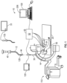
FIG. 1 is a schematic diagram of a microwave ablation procedure system in accordance with an illustrative aspect of the present disclosure; -
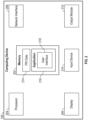
FIG. 2 is a schematic diagram of a computing device which forms part of the microwave ablation procedure system ofFIG. 1 in accordance with an aspect of the present disclosure; -
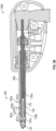
FIG. 3A is a cross-sectional view of a distal portion of a flexible microwave ablation catheter in accordance with an aspect of the present disclosure; -
FIG. 3B is a cross-sectional view of a rigid microwave ablation device in accordance with an aspect of the present disclosure; -
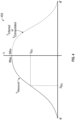
FIG. 4 is a graph illustrating a temperature curve of measured temperature values and extrapolated temperature values of an ablation device in accordance with an aspect of the present disclosure; -
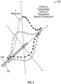
FIG. 5 is an illustration of a volume of temperature gradients of measured temperature values and extrapolated temperature values of an ablation zone in accordance with an aspect of the present disclosure; -
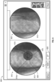
FIG. 6 is an example user interface displayable on a display of the microwave ablation procedure system ofFIG. 1 in accordance with an aspect of the present disclosure; and -
FIG. 7 is a flowchart illustrating a method for optic-based ablation zone simulation in accordance with an aspect of the present disclosure. - The present disclosure provides a system and method for simulating and displaying ablation zones in real time in a microwave ablation treatment procedure using optic-based temperature measurements. In particular, the present disclosure provides an ablation device including fiber Bragg gratings for non-contact inferential sensing of various parameters including temperature, strain, pressure, torque and more. The gratings are embedded via laser etching inside a glass fiber with an explicitly known grating profile associated with the Bragg wavelength or frequency. Exposure to temperature and/or strain causes a broad-spectral pulse of light to reflect off the Bragg grating and shift from the center frequency either up or down in frequency at a known coefficient related to the parameter of interest.
- Incorporating fiber Bragg gratings into a microwave ablation device enables real-time parameter sensing, for example real-time temperature sensing, which can be utilized to inform the treating physician of the dimensions of ablation volume being generated in real time as the application of ablation energy progresses.
- Although the present disclosure will be described in terms of specific illustrative embodiments, it will be readily apparent to those skilled in the art that various modifications, rearrangements, and substitutions may be made without departing from the spirit of the present disclosure. The scope of the present disclosure is defined by the claims appended hereto.
-
Fig. 1 depicts an Electromagnetic Navigation (EMN)system 10 configured for reviewing CT image data to identify one or more targets, planning a pathway to an identified target (planning phase), navigating a catheter 12 (e.g., an extended working channel) of acatheter guide assembly 40 to a target (navigation phase) via a user interface, and confirming placement of thecatheter 12 relative to the target. One such EMN system is the ELECTROMAGNETIC NAVIGATION BRONCHOSCOPY® system currently sold by Medtronic plc. The target may be tissue of interest identified by review of the CT image data during the planning phase. Following navigation, a medical instrument, such as a biopsy tool, ablation tool (e.g., ablation device 130), or other tool, may be inserted into thecatheter 12 to obtain a tissue sample (or perform any treatment) from the tissue located at, or proximate to, the target. Although CT image data is described, any form of imaging data by any imaging device may be utilized prior to, or during, a procedure. - As shown in
Fig. 1 ,catheter 12 is part of acatheter guide assembly 40. In practice, thecatheter 12 is inserted intobronchoscope 30 for access to a luminal network of patient "P." Specifically,catheter 12 ofcatheter guide assembly 40 may be inserted into a working channel ofbronchoscope 30 for navigation through a patient's luminal network. A distal portion of thecatheter 12 includes asensor 44. The position and orientation of thesensor 44 relative to the reference coordinate system, and thus the distal portion of thecatheter 12, within an electromagnetic field can be derived. -
EMN system 10 generally includes an operating table 20 configured to support a patient "P;" abronchoscope 30 configured for insertion through patient's "P's" mouth into patient's "P's" airways; monitoringequipment 120 coupled to bronchoscope 30 (e.g., a video display, for displaying the video images received from the video imaging system of bronchoscope 30); atracking system 50 including atracking module 52, a plurality ofreference sensors 54 and atransmitter mat 56; and acomputing device 100 including software and/or hardware used to facilitate identification of a target, pathway planning to the target, navigation of a medical instrument to the target, and confirmation of placement of ancatheter 12, or a suitable device therethrough, relative to the target. - A
fluoroscopic imaging device 110 capable of acquiring fluoroscopic or x-ray images or video of patient "P" is also included in this particular aspect ofsystem 10. The fluoroscopic data (e.g., images, series of images, or video) captured by thefluoroscopic imaging device 110 may be stored within thefluoroscopic imaging device 110 or transmitted tocomputing device 100 for storage, processing, and display. Additionally, thefluoroscopic imaging device 110 may move relative to patient "P" so that images may be acquired from different angles or perspectives relative to patient "P" to create a fluoroscopic video from a fluoroscopic sweep. The pose offluoroscopic imaging device 110 relative to patient "P" and while capturing the images may be estimated via markers incorporated with thetransmitter mat 56. The markers are positioned under patient "P", between patient "P" and operating table 20 and between patient "P" and a radiation source or a sensing unit offluoroscopic imaging device 110. The markers incorporated with thetransmitter mat 56 may be two separate elements which may be coupled in a fixed manner or alternatively may be manufactured as a single unit.Fluoroscopic imaging device 110 may include a single imaging device or more than one imaging device. In embodiments including multiple imaging devices, each imaging device may be a different type of imaging device or the same type. -
Computing device 100 may be any suitable computing device including a processor and storage medium, wherein the processor is capable of executing instructions stored on the storage medium. Thecomputing device 100 may further include a database configured to store patient data, CT data sets including CT images, fluoroscopic data sets including fluoroscopic images and video, navigation plans, and any other such data. Although not explicitly illustrated, thecomputing device 100 may include inputs, or may otherwise be configured to receive, CT data sets, fluoroscopic images/video and other data described herein. Additionally,computing device 100 includes a display (e.g., display 206) configured to display graphical user interfaces. - With respect to the planning phase,
computing device 100 utilizes previously acquired CT image data for generating and viewing a three-dimensional model or rendering of patient "P's" airways, enables the identification of a target on the three-dimensional model (automatically, semiautomatically, or manually), and allows for determining a pathway through patient "P's" airways to tissue located at and around the target. More specifically, CT images acquired from previous CT scans are processed and assembled into a three-dimensional CT volume, which is then utilized to generate a three-dimensional model of patient "P's" airways. The three-dimensional model may be displayed on adisplay 206 associated withcomputing device 100, or in any other suitable fashion. Usingcomputing device 100, various views of the three-dimensional model or enhanced two-dimensional images generated from the three-dimensional model are presented. The enhanced two-dimensional images may possess some three-dimensional capabilities because they are generated from three-dimensional data. The three-dimensional model may be manipulated to facilitate identification of target on the three-dimensional model or two-dimensional images, and selection of a suitable pathway through patient "P's" airways to access tissue located at the target can be made. Once selected, the pathway plan, three-dimensional model, and images derived therefrom, can be saved and exported to a navigation system for use during the navigation phase(s). One such planning software is the ILLUMISITE® planning suite currently sold by Medtronic plc. - With respect to the navigation phase, a six degrees-of-freedom
electromagnetic tracking system 50, or other suitable positioning measuring system, is utilized for performing registration of the images and the pathway for navigation, although other configurations are also contemplated.Tracking system 50 includes atracking module 52, a plurality ofreference sensors 54, and a transmitter mat 56 (including markers if applicable).Tracking system 50 is configured for use with asensor 44 ofcatheter guide assembly 40 to track the electromagnetic position thereof within an electromagnetic coordinate system. -
Transmitter mat 56 is positioned beneath patient "P."Transmitter mat 56 generates an electromagnetic field around at least a portion of patient "P" within which the position of a plurality ofreference sensors 54 and thesensor 44 can be determined with use of atracking module 52. A secondelectromagnetic sensor 126 may also be incorporated into the end of thecatheter 12. The secondelectromagnetic sensor 126 may be a five degree-of-freedom sensor or a six degree-of-freedom sensor. One or more ofreference sensors 54 are attached to the chest of patient "P." The six degrees of freedom coordinates ofreference sensors 54 are sent to computing device 100 (which includes the appropriate software) where they are used to calculate a patient coordinate frame of reference. Registration, as detailed below, is generally performed to coordinate locations of the three dimensional model and two dimensional images from the planning phase with patient's "P's" airways as observed through thebronchoscope 30, and allow for the navigation phase to be undertaken with precise knowledge of the location of thesensor 44, even in portions of the airway where thebronchoscope 30 cannot reach. - Registration of patient's "P's" location on the
transmitter mat 56 is performed by movingsensor 44 through the airways of patient's "P." More specifically, data pertaining to locations ofsensor 44, whilecatheter 12 is moving through the airways, is recorded usingtransmitter mat 56,reference sensors 54, and trackingmodule 52. A shape resulting from this location data is compared to an interior geometry of passages of the three dimensional model generated in the planning phase, and a location correlation between the shape and the three dimensional model based on the comparison is determined, e.g., utilizing the software oncomputing device 100. In addition, the software identifies non-tissue space (e.g., air filled cavities) in the three dimensional model. The software aligns, or registers, an image representing a location ofsensor 44 with the three dimensional model and two dimensional images generated from the three dimension model, which are based on the recorded location data and an assumption thatsensor 44 remains located in non-tissue space in patient's "P's" airways. Alternatively, a manual registration technique may be employed by navigating thebronchoscope 30 with thesensor 44 to pre-specified locations in the lungs of patient "P", and manually correlating the images from the bronchoscope to the model data of the three dimensional model. - Though described herein with respect to EMN systems using EM sensors, the instant disclosure is not so limited and may be used in conjunction with flexible sensor, ultrasonic sensors, or without sensors. Additionally, the methods described herein may be used in conjunction with robotic systems such that robotic actuators drive the
catheter 12,catheter guide assembly 40 components, orbronchoscope 30 proximate the target. - Following registration of patient "P" to the image data and pathway plan, a user interface is displayed in the navigation software which sets forth the pathway that the clinician is to follow to reach the target.
- Once
catheter 12 has been successfully navigated proximate the target as depicted on the user interface, thecatheter 12 is in place as a guide channel for guiding medical instruments including without limitation, optical systems, ultrasound probes, marker placement tools, biopsy tools, ablation tools (i.e., microwave ablation devices), laser probes, cryogenic probes, sensor probes, and aspirating needles to the target. In an aspect,ablation device 130 is a flexiblemicrowave ablation catheter 130a (FIG. 3A ) which is guided throughcatheter 12 for placement relative to a target and ablation of the target. - Prior to inserting the medical device through the
catheter 12, a local registration process may be performed for each target to reduce the CT-to-body divergence. In a capture phase of the local registration process, a sequence of fluoroscopic images may be captured and acquired viafluoroscopic imaging device 110, optionally by a user and according to directions displayed viacomputing device 100. A fluoroscopic 3D reconstruction may be then generated viacomputing device 100. The generation of the fluoroscopic 3D reconstruction is based on the sequence of fluoroscopic images and the projections of structure of markers incorporated withtransmitter mat 56 on the sequence of images. One or more slices of the 3D reconstruction may be then generated based on the pre-operative CT scan and viacomputing device 100. The one or more slices of the 3D reconstruction and the fluoroscopic 3D reconstruction may be then displayed to the user on a display viacomputing device 100, optionally simultaneously. The slices of 3D reconstruction may be presented on the user interface in a scrollable format where the user is able to scroll through the slices in series. Additionally, or alternatively, other imaging modalities such as CT or cone beam CT may be utilized. -
Ablation device 130 is a surgical instrument having a microwave ablation antenna that is used to ablate tissue, such as a lesion or tumor, by using electromagnetic radiation or microwave energy to heat tissue in order to denature or kill cancerous cells.Ablation device 130 may be a flexiblemicrowave ablation catheter 130a (FIG. 3A ) configured to be navigated to a target via a patient's luminal network through acatheter 12 that has been navigated to the target. Alternatively,ablation device 130 may be a rigidmicrowave ablation device 130b (FIG. 3B ) configured to be percutaneously inserted through tissue to access a target within a patient.Ablation device 130 is configured to connect to microwave generator 33 (FIG. 1 ) which generates and controls the application of microwave energy through theablation device 130.Microwave generator 33 may be a component ofcomputing device 100 or may be a separate stand-alone component.Ablation device 130 is described in further detail below with respect toFIGS. 3A and3B . -
FIG. 2 illustrates a system diagram ofcomputing device 100.Computing device 100 may includememory 202,processor 204,display 206,network interface 208,input device 210, and/oroutput module 212.Memory 202 includes any non-transitory computer-readable storage media for storing data and/or software that is executable byprocessor 204 and which controls the operation ofcomputing device 100. In an embodiment,memory 202 may include one or more solid-state storage devices such as flash memory chips. Alternatively or in addition to the one or more solid-state storage devices,memory 202 may include one or more mass storage devices connected to theprocessor 204 through a mass storage controller (not shown) and a communications bus (not shown). Although the description of computer-readable media contained herein refers to a solid-state storage, it should be appreciated by those skilled in the art that computer-readable storage media can be any available media that can be accessed by theprocessor 204. That is, computer readable storage media includes non-transitory, volatile and non-volatile, removable and non-removable media implemented in any method or technology for storage of information such as computer-readable instructions, data structures, program modules, or other data. For example, computer-readable storage media includes RAM, ROM, EPROM, EEPROM, flash memory or other solid state memory technology, CD-ROM, DVD, Blu-Ray or other optical storage, magnetic cassettes, magnetic tape, magnetic disk storage or other magnetic storage devices, or any other medium which can be used to store the desired information and which can be accessed by computingdevice 100. -
Memory 202 may storeapplication 216 and/or functionalrespiratory imaging data 214 of one or more patients.Application 216 may, when executed byprocessor 204,cause display 206 to present user interfaces.Processor 204 may be a general-purpose processor, a specialized graphics processing unit (GPU) configured to perform specific graphics processing tasks while freeing up the general-purpose processor to perform other tasks, and/or any number or combination of such processors.Display 206 may be touch sensitive and/or voice activated, enablingdisplay 206 to serve as both an input and output device. Alternatively, a keyboard (not shown), mouse (not shown), or other data input devices may be employed.Network interface 208 may be configured to connect to a network such as a local area network (LAN) consisting of a wired network and/or a wireless network, a wide area network (WAN), a wireless mobile network, a Bluetooth network, and/or the internet. For example,computing device 100 may receive functional respiratory imaging data, DICOM imaging data, computed tomographic (CT) image data, or other imaging data, of a patient from an imaging workstation 150 and/or a server, for example, a hospital server, internet server, or other similar servers, for use during surgical ablation planning. Patient functional respiratory imaging data may also be provided tocomputing device 100 via aremovable memory 202.Computing device 100 may receive updates to its software, for example,application 216, vianetwork interface 208.Computing device 100 may also display notifications ondisplay 206 that a software update is available. -
Input device 210 may be any device by means of which a user may interact withcomputing device 100, such as, for example, a mouse, keyboard, foot pedal, touch screen, and/or voice interface.Output module 212 may include any connectivity port or bus, such as, for example, parallel ports, serial ports, universal serial busses (USB), or any other similar connectivity port known to those skilled in the art. -
Application 216 may be one or more software programs stored inmemory 202 and executed byprocessor 204 ofcomputing device 100. During a planning phase,application 216 guides a clinician through a series of steps to identify a target, size the target, size a treatment zone, and/or determine an access route to the target for later use during the procedure phase. In some embodiments,application 216 is loaded on computing devices in an operating room or other facility where surgical procedures are performed, and is used as a plan or map to guide a clinician performing a surgical procedure, but without any feedback fromablation device 130 used in the procedure to indicate whereablation device 130 is located in relation to the plan. In other embodiments,system 10 providescomputing device 100 with data regarding the location ofablation device 130 within the body of the patient, such as by EM tracking, whichapplication 216 may then use to indicate on the plan whereablation device 130 is located. -
Application 216 may be installed directly oncomputing device 100, or may be installed on another computer, for example, a central server, and opened oncomputing device 100 vianetwork interface 208.Application 216 may run natively oncomputing device 100, as a web-based application, or any other format known to those skilled in the art. In some embodiments,application 216 will be a single software program having all of the features and functionality described in the present disclosure. In other embodiments,application 216 may be two or more distinct software programs providing various parts of these features and functionality. For example,application 216 may include one software program for use during the planning phase, and a second software program for use during the procedure phase of the microwave ablation treatment. In such instances, the various software programs forming part ofapplication 216 may be enabled to communicate with each other and/or import and export various settings and parameters relating to the microwave ablation treatment and/or the patient to share information. For example, a treatment plan and any of its components generated by one software program during the planning phase may be stored and exported to be used by a second software program during the procedure phase. -
Application 216 communicates with auser interface 218 that generates a user interface for presenting visual interactive features to a clinician, for example, ondisplay 206 and for receiving clinician input, for example, via a user input device. For example,user interface 218 may generate a graphical user interface (GUI) and output the GUI to display 206 for viewing by a clinician. -
Computing device 100 is linked to display 120, thus enablingcomputing device 100 to control the output ondisplay 120 along with the output ondisplay 206.Computing device 100 may controldisplay 120 to display output which is the same as or similar to the output displayed ondisplay 206. For example, the output ondisplay 206 may be mirrored ondisplay 120. Alternatively,computing device 100 may controldisplay 120 to display different output from that displayed ondisplay 206. For example,display 120 may be controlled to display guidance images and information during the microwave ablation procedure, whiledisplay 206 is controlled to display other output, such as configuration or status information. -
FIG. 3A illustrates a distal portion of a flexiblemicrowave ablation catheter 130a andFIG. 3B illustrates a rigidmicrowave ablation device 130b (referred to collectively as ablation device 130). Theablation device 130 includes adistal tip 137 which may be blunt or may include a tapered trocar tip for percutaneous insertion through tissue. Theablation device 130 includes a radiatingantenna 135 which includes aproximal radiating section 135a and adistal radiating section 135b, which are configured to emit microwave energy into the tissue surrounding the radiatingantenna 135. A coolingtube 134 is positioned relative to the radiatingantenna 135 for passage of a cooling fluid therethrough to cool the radiatingantenna 135 during application of microwave energy. Anouter jacket 132 defines alumen 132a and surrounds both of thecooling tube 134 and the radiatingantenna 135. The coolingtube 134 may be positioned adjacent and alongside the radiatingantenna 135 within thelumen 132a of theouter jacket 132 or the radiatingantenna 135 may be positioned within the coolingtube 134. In percutaneous applications, the rigidmicrowave ablation device 130b includes anouter jacket 132 formed of a rigid material so as to maintain it's shape during percutaneous insertion of the rigidmicrowave ablation device 130b through tissue to a target. Alternatively, in lung navigation applications, the flexiblemicrowave ablation catheter 130a may include anouter jacket 132 which is formed of a flexible or semi-rigid material capable of being navigated through a catheter (e.g., catheter 12) to a target. - The
ablation device 130 includes afiber 300 which may be coupled to theouter jacket 132. In aspects, thefiber 300 is embedded into theouter jacket 132. Alternatively, thefiber 300 may be positioned in thelumen 132a of theouter jacket 132 or on an outer surface of theouter jacket 132. In aspects, thefiber 300 may be retrofitted to anablation device 130 by securing thefiber 300 to theouter jacket 132 via heat-shrink or other mediums. A proximal end of thefiber 300 may be incorporated into a connector of theablation device 130 which connects theablation device 130 to a microwave generator (e.g., microwave generator 33), or alternatively, a separate independent connector may be utilized to connect the proximal end of thefiber 300 to the microwave generator,computing device 100, or another component ofsystem 10. -
Fiber 300 includes a plurality of Bragg gratings 302a, 302b, ...302n (referred to collectively as Bragg gratings 302) etched into thefiber 300. TheBragg gratings 302 reflect a narrow wavelength range called the Bragg wavelength. Each Bragg grating 302 includes periodic modulations in the core of thefiber 300 with spacing between each modulation. This changes the refractive index of thefiber 300 so that a single wavelength is reflected, while the rest of the light is transmitted down thefiber 300. The spacing between modulations changes when a Bragg grating 302 is subjected to a change in temperature. This changes the refractive index of the Bragg grating 302 and causes the Bragg wavelength to shift. Embodiments of the present disclosure use the shift in the Bragg wavelength to determine a temperature. TheBragg gratings 302 may be integrated at points of interest along the length of theablation device 130. For example, in aspects, theBragg gratings 302 are spaced 10-50 mm on the proximal length of theablation device 130 and spaced between 1-5 mm at the distal portion of theablation device 130 where electromagnetic radiation and subsequent temperature change is likely to occur. - The
Bragg gratings 302 include a plurality ofreflection points fiber 300 at periodic spacing "A." In some embodiments, theBragg gratings 302 may be written into thefiber 300 using high intensity pulses from a laser (e.g., argon fluoride excimer laser with a phase mask). As thefiber 300 undergoes mechanical strain (e.g., a change in length) due to temperature and pressure changes, the spacing A is modified due to stretching or contraction of thefiber 300. The effects of changes in temperature on thefiber 300 is quantified by thecomputing device 100 by measuring the wavelength shift in light reflected by the reflection points 321 based on the following equation:

- In equation (1), Δλ is the wavelength shift, λ0 is the base wavelength, k is a gauge factor, which is a difference between 1 and a photo-elastic coefficient, p, ε is strain, ΔT is a temperature change, and αδ is a change of the refraction index.
- In this manner,
fiber 300 is configured to transmit at least one wavelength of light and theBragg gratings 302 are configured to reflect at least one wavelength of light. Thus, the light transmissive properties, namely transmittance, of the distal portion of thefiber 300 corresponds to a set of physical parameters of theablation device 130 or the environment in which it is positioned (e.g., temperature of tissue). In particular, changes in temperature and pressure affect (e.g., stretch or contract) the distal portion of theoptical fiber 300, which, in turn, modifies the spacing between the Bragg gratings 302. The changes in spacing between theBragg gratings 302 changes the wavelength of the light reflected back through thefiber 300. The change in the wavelength is then used by thecomputing device 100 to determine the change in temperatures at the locations of the Bragg gratings 302. - The
computing device 100 includes a fiber grating demodulator, which demodulates the reflected light transmitted throughfiber 300 using a demodulation technique to obtain the changes in wavelength. Demodulation techniques include wavelength division multiplexing (WDM), optical time domain reflectometry (OTDM), optical frequency domain reflectometry (OFDM), and code correlation techniques that incorporate aspects of OTDM and OFDM. According to the OTDR technique, a narrow light pulse is generated by a light source and is transmitted through theoptical fiber 300 to the fiber Bragg gratings 302. The reflected or backscattered light is analyzed to determine multiple temperatures. The locations corresponding to each of the temperatures may be determined by monitoring the time it takes the reflected or backscattered light to return to the photodetector. - The temperature measurements sensed by computing
device 100 may be displayed and/or may be used to control aspects of thesystem 10, for example, to control output of themicrowave generator 33. In embodiments, the data is extrapolated during application of microwave ablation energy to simulate the volumetric geometry of the ablation zone as the ablation procedure progresses. In particular, thecomputing device 100 observes a gradient of temperature or strain shift by the grating wavelength shifts in thefiber 300 when the radiatingantenna 135 of theablation device 130 is emitting microwave energy. This gradient should be at a peak at a location nearest to the radiatingantenna 135 and is expected to fall off to a minimum at a point furthest away from the radiatingantenna 135. At some distance from the radiatingantenna 135, where the electromagnetic field has dropped off substantially (e.g., above or below a predetermined threshold), the temperature will approach an asymptote that matches the environmental temperature surrounding the radiating antenna 135 (e.g., the assumed temperature of the human body of 37 degrees C). - With reference to
FIGS. 4 and5 , utilizing thetemperature curve 400 of measured temperature values and extrapolated or inferred temperature values,computing device 100 may sweep thetemperature curve 400 around all three axes (X, Y, Z) to create a volume oftemperature gradients 500. A region of interest may be the point where 60 degrees C is measured and the range of tissue below 60 degrees C is measured as this is where cell death should not be expected. Parameters to a given procedure (e.g., ablation zone dimensions, ablation zone edges, etc.) may be identified based on temperature values alone, total energy deposited (time x power), and/or temperature dwell periods to identify a region of likely necrosis. The total final expected ablation zone (derived from power to be delivered x time to be delivered, for example) may be projected and compared to the actual ablation zone dimensions in real time as the thermal field grows during the application of microwave energy. In this manner, a clinician may visualize the progression of the ablation zone relative to the desired final ablation zone to be expected upon the full application of energy for the full time allotted, thus providing intraprocedural guidance to how the treatment is developing and progressing in real time. - Utilizing the example shown in
FIGS. 4 and5 , the radiated field may be assumed to be perfectly spherical or substantially spherical (e.g., an ablation zone with a shape approaching a sphere but not necessarily perfectly spherical) which is appropriate for certain models ofablation devices 130. For other ablation devices configured to generate non-spherical ablation zones (e.g., ovoid, elongated, oblong, etc.), K parameters may be incorporated into the volumetric calculations and compared with pre-operative known in-vivo measurements to tune the intraoperative expected volume and measured volumes to match each other. Such K parameters can be known and stored within the memory of thecomputing device 100 or may be based on calibration parameters stored within theablation device 130. -
FIG. 6 illustrates anexample user interface 600 displayable on one or both ofdisplay 120 anddisplay 206 during an ablation procedure. During an ablation procedure, the clinician navigates ablation device 130 (displayed asablation device 614 on the user interface 600) along a pathway to the target (e.g., utilizing an imaging device such as, for example, a fluoroscopic, CT, ultrasound, or hybrid three dimensional fluoro-CT imaging device, to visualize placement of theablation device 130 relative to the target). Whileablation device 130 is navigated,application 216 tracks the location ofablation device 130 or a catheter through which theablation device 130 is placed inside the patient's body and displays the tracked location ofablation device 130 or catheter overlayed onto imaging data of the patient (e.g., patient CT data, ultrasound imaging data, fluoroscopic imaging data, hybrid three dimensional fluoro-CT imaging data, etc.) on the user interface. In addition, theapplication 216 may project a vector displayable on theuser interface 600 extending from the end of theablation device 130 to give an indication to the clinician of the intersecting tissue along the trajectory of theablation device 130. In this manner, the clinician can alter the approach to a lesion or tumor to optimize the placement with minimum of trauma or follow a planned pathway to the target. -
User interface 600 includes aview 602 of thepatient images 613 captured during the procedure or captured preoperatively. For example, view 602 may include a three dimensional rendering of the patient's lungs generated from DICOM data.User interface 600 also includes a view for displaying status messages relating to the ablation procedure, such as a power setting 616 of theablation device 130 orgenerator 33, duration of the ablation and/or a time remaining until the ablation procedure is complete, progression of the ablation, and/ortemperature feedback 608 from a temperature sensor.User interface 600 also displays thenavigation view 612, which includes a representation 314 ofablation device 130 as well as ashadow indicator 614a representing the portion ofablation device 130 which lies below a displayed two dimensional or three dimensional imaging plane, a simulation ofablation growth 618 representing the progression of the growth of the ablation zone during application of energy overlayed onto thepatient images 613, and a total predictedablation zone 620 representing the area which will be ablated if the ablation procedure is allowed to run to completion. Thenavigation view 612 may include three dimensional renderings generated from DICOM image data, for example, a three dimensional rendering generated from a CT scan of the patient. - As described above, the computing device extrapolates the volumetric dimensions of the ablation zone from the fiber optic-based temperature measurements which is displayed as the simulation of
ablation growth 618 over time. The simulation ofablation growth 618 may include a solid outer edge which increases in size based on the duration of energy application and/or the real time fiber optic-based temperature measurements, a jagged line outer edge which moves and increases in size based on the duration of energy application and/or the real time fiber optic-based temperature measurements, and/or a pulsing line outer edge which fades between appearing and disappearing and which increases in size based on the duration of energy application and/or the real time fiber optic-based temperature measurements. The appearing and disappearing pulsing line of the simulation ofablation growth 618 prevents the simulation ofablation growth 618 from blocking visibility of objects in the displayedpatient images 613. - Turning to
FIG. 7 , a method for generating and displaying an ablation zone volume is illustrated and described asmethod 700.Method 700 is described as being executed by computingdevice 100, but some or all of the steps ofmethod 700 may be implemented by one or more other components of thesystem 10, alone or in combination. Additionally, althoughmethod 700 is illustrated and described as including specific steps, and is described as being carried out in a particular order, it is understood thatmethod 700 may include some or all of the steps described and may be carried out in any order not specifically described. -
Method 700 begins atstep 701 wherecomputing device 100 acquires preoperative CT data of a patient's lungs to identify one or more targets requiring ablation. Instep 703, anablation device 130 is navigated to the target. For example, theablation device 130 may be a flexiblemicrowave ablation catheter 130a (FIG. 3A ) which is navigated to the target through a patient's luminal airways. Alternatively, theablation device 130 may be a rigidmicrowave ablation device 130b (FIG. 3B ) which is percutaneously inserted through a patient's tissue to access the target. - In
step 705, subsequent to final placement of theablation device 130 relative to the target, the application of microwave energy to theablation device 130 for ablating the target is initiated. Instep 707, thecomputing device 100 processes the light reflected fromfiber Bragg gratings 302 of theablation device 130 to calculate a temperature at thefiber Bragg gratings 302, for example along a length of theablation device 130. Step 707 may additionally include monitoring the amount of time it takes the reflected or backscattered light to return to a photodetector and determining the location of the temperature measurement along the length of theablation device 130 corresponding to each reflected light signal based on the amount of time monitored. - In
step 709, thecomputing device 100 extrapolates the temperature values calculated instep 707 to generate an ablation volume over the course of the duration of the ablation procedure. The ablation volume ofstep 709 may additionally be based on additional factors such as duration of energy application, total energy deposited, and/or temperature dwell periods. Step 709 may additionally include identifying a perimeter of an ablation zone based on one or more of the factors listed above. Step 709 is carried out by computing device throughout the course of the application of microwave ablation energy as the size of the ablation zone volume increases, in real time to show the growth of the ablation zone volume as the ablation procedure progresses. - In
step 711, the ablation volume generated instep 709 is displayed on a display ofcomputing device 100 for viewing by a clinician during the application of microwave ablation energy. The display of the generated ablation zone volume instep 711 is constantly updated in real time as the ablation zone increases in time. In this manner, the clinician is able to visualize a simulation of ablation zone growth as the procedure progresses. Step 711 may include overlaying the simulated ablation zone onto preoperative or intraoperative images of the patient. Additionally, the displayed simulation of the ablation zone volume may be displayed relative to an estimated total ablation zone, which represents the total ablation zone expected to be achieved upon completion of the ablation procedure, so that clinician can easily visualize the extent of the ablation zone and the remaining are expected to be ablated. - Although embodiments have been described in detail with reference to the accompanying drawings for the purpose of illustration and description, it is to be understood that the inventive processes and apparatus are not to be construed as limited thereby. It will be apparent to those of ordinary skill in the art that various modifications to the foregoing embodiments may be made without departing from the scope of the disclosure.
- The invention may be described by reference to the following numbered paragraphs:-
- 1. An ablation system comprising:
- an ablation device including:
- a radiating antenna configured to apply microwave ablation energy to a target within a patient to ablate the target; and
- a fiber including Bragg gratings formed along a length thereof and configured to reflect light therefrom;
- a computing device including a processor and memory storing instructions which, when executed by the processor, cause the computing device to:
- calculate temperature measurements based on the reflected light during application of microwave ablation energy to the target; and
- extrapolate the temperature measurements calculated to generate an ablation volume in real time.
- an ablation device including:
- 2. The ablation system of paragraph 1, further comprising a display operably coupled to the computing device, wherein the computing device is configured to cause the display to display a progression of the ablation volume in real time.
- 3. The ablation system of paragraph 2, wherein the computing device is configured to cause the display to overlay the ablation volume onto an image of the target within the patient.
- 4. The ablation system of paragraph 2, wherein the computing device is configured to:
- calculate a total expected ablation zone;
- cause the display to display the total expected ablation zone onto an image of the target within the patient; and
- cause the display to display the progression of the ablation volume within the display of the total expected ablation zone.
- 5. The ablation system of paragraph 1, wherein the Bragg gratings are etched into the fiber.
- 6. The ablation system of paragraph 1, wherein the ablation device is a flexible microwave ablation catheter configured to be navigated to the target through a patient's luminal network.
- 7. The ablation system of paragraph 1, wherein the ablation device is a rigid microwave ablation device configured to be percutaneously inserted through tissue to access the target.
- 8. The ablation system of paragraph 1, wherein the computing device is configured to generate the ablation volume based on the extrapolated temperature measurements, a total amount of microwave ablation energy applied, and a duration of energy application.
- 9. The ablation system of paragraph 1, wherein the computing device is configured to:
- determine an expected ablation zone geometry to be formed by the ablation device based on a model of the ablation device; and
- extrapolate the temperature measurements based on the expected ablation zone geometry determined.
- 10. The ablation system of paragraph 9, wherein the expected ablation zone geometry is substantially spherically shaped, and the computing device is configured to extrapolate the temperature measurements based on the substantially spherical shape.
- 11. An ablation system comprising:
a computing device including a processor and memory storing instructions which, when executed by the processor, cause the computing device to:- receive reflected light from fiber Bragg gratings of an ablation device;
- calculate temperature measurements based on the reflected light during application of microwave ablation energy by the ablation device to a target within a patient;
- extrapolate the temperature measurements calculated to generate an ablation volume in real time;
- cause a display device to display an image of the target; and
- cause the display device to overlay a progression of the ablation volume onto the image of the target.
- 12. The ablation system of paragraph 11, wherein the image of the target is a three dimensional rendering of a portion of the patient generated from at least one of DICOM images or fluoroscopic images.
- 13. The ablation system of paragraph 11, wherein the computing device is configured to:
- calculate a total expected ablation zone;
- cause the display to display the total expected ablation zone onto an image of the target within the patient; and
- cause the display to display the progression of the ablation volume within the display of the total expected ablation zone.
- 14. The ablation system of paragraph 11, wherein the computing device is configured to generate the ablation volume based on the extrapolated temperature measurements, a total amount of microwave ablation energy applied, and a duration of energy application.
- 15. A method for optic-based ablation zone simulation comprising:
- receiving reflected light from fiber Bragg gratings of an ablation device;
- calculating temperature measurements based on the reflected light during application of microwave ablation energy by the ablation device to a target within a patient;
- extrapolating the temperature measurements calculated to generate an ablation volume in real time;
- causing a display device to display an image of the target; and
- causing the display device to overlay a progression of the ablation volume onto the image of the target.
- 16. The method of paragraph 15, wherein causing the display device to display the image of the target includes causing the display device to display a three dimensional rendering of a portion of the patient generated from at least one of DICOM images or fluoroscopic images.
- 17. The method of paragraph 15, further comprising calculating a total expected ablation zone based on one or more of a type of ablation device, a total power setting, and a total duration of application of microwave energy.
- 18. The method of paragraph 17, further comprising causing the display to display the total expected ablation zone calculated onto an image of the target within the patient.
- 19. The method of paragraph 18, further comprising causing the display to display the progression of the ablation volume within the display of the total expected ablation zone calculated.
- 20. The method of paragraph 15, wherein extrapolating the temperature measurements calculated to generate the ablation volume in real time includes generating the ablation volume based on the extrapolated temperature measurements, a total amount of microwave ablation energy applied, and a duration of energy application.
Claims (15)
- An ablation system comprising:an ablation device including:a radiating antenna configured to apply microwave ablation energy to a target within a patient to ablate the target; anda fiber including Bragg gratings formed along a length thereof and configured to reflect light therefrom;a computing device including a processor and memory storing instructions which, when executed by the processor, cause the computing device to:calculate temperature measurements based on the reflected light during application of microwave ablation energy to the target; andextrapolate the temperature measurements calculated to generate an ablation volume in real time.
- The ablation system of claim 1, further comprising a display operably coupled to the computing device, wherein the computing device is configured to cause the display to display a progression of the ablation volume in real time.
- The ablation system of claim 2, wherein the computing device is configured to cause the display to overlay the ablation volume onto an image of the target within the patient.
- The ablation system of claim 2 or claim 3, wherein the computing device is configured to:calculate a total expected ablation zone;cause the display to display the total expected ablation zone onto an image of the target within the patient; andcause the display to display the progression of the ablation volume within the display of the total expected ablation zone.
- The ablation system of any preceding claim, wherein the Bragg gratings are etched into the fiber and/or wherein the ablation device is a flexible microwave ablation catheter configured to be navigated to the target through a patient's luminal network.
- The ablation system of any preceding claim, wherein the ablation device is a rigid microwave ablation device configured to be percutaneously inserted through tissue to access the target and/or wherein the computing device is configured to generate the ablation volume based on the extrapolated temperature measurements, a total amount of microwave ablation energy applied, and a duration of energy application.
- The ablation system of any preceding claim, wherein the computing device is configured to:determine an expected ablation zone geometry to be formed by the ablation device based on a model of the ablation device; andextrapolate the temperature measurements based on the expected ablation zone geometry determined; preferably wherein the expected ablation zone geometry is substantially spherically shaped, and the computing device is configured to extrapolate the temperature measurements based on the substantially spherical shape.
- An ablation system comprising:
a computing device including a processor and memory storing instructions which, when executed by the processor, cause the computing device to:receive reflected light from fiber Bragg gratings of an ablation device;calculate temperature measurements based on the reflected light during application of microwave ablation energy by the ablation device to a target within a patient;extrapolate the temperature measurements calculated to generate an ablation volume in real time;cause a display device to display an image of the target; andcause the display device to overlay a progression of the ablation volume onto the image of the target. - The ablation system of claim 8, wherein the image of the target is a three dimensional rendering of a portion of the patient generated from at least one of DICOM images or fluoroscopic images.
- The ablation system of claim 8 or claim 9, wherein the computing device is configured to:calculate a total expected ablation zone;cause the display to display the total expected ablation zone onto an image of the target within the patient; andcause the display to display the progression of the ablation volume within the display of the total expected ablation zone.
- The ablation system of any of claims 8 to 10, wherein the computing device is configured to generate the ablation volume based on the extrapolated temperature measurements, a total amount of microwave ablation energy applied, and a duration of energy application.
- A method for optic-based ablation zone simulation comprising:receiving reflected light from fiber Bragg gratings of an ablation device;calculating temperature measurements based on the reflected light during application of microwave ablation energy by the ablation device to a target within a patient;extrapolating the temperature measurements calculated to generate an ablation volume in real time;causing a display device to display an image of the target; andcausing the display device to overlay a progression of the ablation volume onto the image of the target.
- The method of claim 12, wherein causing the display device to display the image of the target includes causing the display device to display a three dimensional rendering of a portion of the patient generated from at least one of DICOM images or fluoroscopic images; preferably further comprising calculating a total expected ablation zone based on one or more of a type of ablation device, a total power setting, and a total duration of application of microwave energy.
- The method of claim 12 or claim 13, further comprising causing the display to display the total expected ablation zone calculated onto an image of the target within the patient; preferably further comprising causing the display to display the progression of the ablation volume within the display of the total expected ablation zone calculated.
- The method of any of claims 12 to 14, wherein extrapolating the temperature measurements calculated to generate the ablation volume in real time includes generating the ablation volume based on the extrapolated temperature measurements, a total amount of microwave ablation energy applied, and a duration of energy application.
Applications Claiming Priority (2)
| Application Number | Priority Date | Filing Date | Title |
|---|---|---|---|
| US202363437417P | 2023-01-06 | 2023-01-06 | |
| US18/498,326 US20240225728A1 (en) | 2023-01-06 | 2023-10-31 | System and method for optic-based ablation zone simulation |
Publications (2)
| Publication Number | Publication Date |
|---|---|
| EP4397266A1 true EP4397266A1 (en) | 2024-07-10 |
| EP4397266B1 EP4397266B1 (en) | 2026-07-08 |
Family
ID=89508955
Family Applications (1)
| Application Number | Title | Priority Date | Filing Date |
|---|---|---|---|
| EP24150507.2A Active EP4397266B1 (en) | 2023-01-06 | 2024-01-05 | System for optic-based ablation zone simulation |
Country Status (2)
| Country | Link |
|---|---|
| US (1) | US20240225728A1 (en) |
| EP (1) | EP4397266B1 (en) |
Families Citing this family (1)
| Publication number | Priority date | Publication date | Assignee | Title |
|---|---|---|---|---|
| US20240285332A1 (en) * | 2023-02-24 | 2024-08-29 | Neuwave Medical, Inc. | Temperature regulating devices and related systems and methods |
Citations (2)
| Publication number | Priority date | Publication date | Assignee | Title |
|---|---|---|---|---|
| CN109984734A (en) * | 2019-03-12 | 2019-07-09 | 南京航空航天大学 | A kind of multiple spot tumor thermotherapy thermometric needle based on fiber bragg grating |
| US20210361353A1 (en) * | 2017-08-31 | 2021-11-25 | Covidien Lp | Systems and methods for sensing temperature at different locations on a microwave antenna using ultiple fiber sensors |
-
2023
- 2023-10-31 US US18/498,326 patent/US20240225728A1/en active Pending
-
2024
- 2024-01-05 EP EP24150507.2A patent/EP4397266B1/en active Active
Patent Citations (2)
| Publication number | Priority date | Publication date | Assignee | Title |
|---|---|---|---|---|
| US20210361353A1 (en) * | 2017-08-31 | 2021-11-25 | Covidien Lp | Systems and methods for sensing temperature at different locations on a microwave antenna using ultiple fiber sensors |
| CN109984734A (en) * | 2019-03-12 | 2019-07-09 | 南京航空航天大学 | A kind of multiple spot tumor thermotherapy thermometric needle based on fiber bragg grating |
Also Published As
| Publication number | Publication date |
|---|---|
| US20240225728A1 (en) | 2024-07-11 |
| EP4397266B1 (en) | 2026-07-08 |
Similar Documents
| Publication | Publication Date | Title |
|---|---|---|
| US12458206B2 (en) | Systems and methods for intraoperative segmentation | |
| CN112386336B (en) | Systems and methods for fluorescence-CT imaging for initial registration | |
| KR102590620B1 (en) | Robotic devices for minimally invasive medical interventions in soft tissues | |
| US10314564B2 (en) | Computed tomography enhanced fluoroscopic system, device, and method of utilizing the same | |
| EP3170456B1 (en) | Systems and methods for ultrasound image-guided ablation antenna placement | |
| US9782147B2 (en) | Apparatus and methods for localization and relative positioning of a surgical instrument | |
| US10561462B2 (en) | System and method for temperature feedback for adaptive radio frequency ablation | |
| US9147289B2 (en) | Method for visualizing the quality of an ablation process | |
| WO2020072360A1 (en) | Graphical user interface for defining an anatomical boundary | |
| CN109561832B (en) | Method for predicting respiratory cycle and improving end registration using soft-point features | |
| US20240225728A1 (en) | System and method for optic-based ablation zone simulation | |
| CN118303974A (en) | Optical-based ablation zone simulation system and method | |
| US20260083497A1 (en) | System for ablation zone prediction | |
| WO2024150096A1 (en) | System for optic-based filtered telemetry measurements | |
| US12564371B2 (en) | System and method for displaying ablation zone progression | |
| US12303209B2 (en) | Systems for evaluating registerability of anatomic models and associated methods | |
| WO2024241218A1 (en) | System and method for updating registration and localization during surgical navigation |
Legal Events
| Date | Code | Title | Description |
|---|---|---|---|
| PUAI | Public reference made under article 153(3) epc to a published international application that has entered the european phase |
Free format text: ORIGINAL CODE: 0009012 |
|
| STAA | Information on the status of an ep patent application or granted ep patent |
Free format text: STATUS: REQUEST FOR EXAMINATION WAS MADE |
|
| 17P | Request for examination filed |
Effective date: 20240105 |
|
| AK | Designated contracting states |
Kind code of ref document: A1 Designated state(s): AL AT BE BG CH CY CZ DE DK EE ES FI FR GB GR HR HU IE IS IT LI LT LU LV MC ME MK MT NL NO PL PT RO RS SE SI SK SM TR |
|
| GRAP | Despatch of communication of intention to grant a patent |
Free format text: ORIGINAL CODE: EPIDOSNIGR1 |
|
| STAA | Information on the status of an ep patent application or granted ep patent |
Free format text: STATUS: GRANT OF PATENT IS INTENDED |
|
| INTG | Intention to grant announced |
Effective date: 20260218 |
|
| GRAS | Grant fee paid |
Free format text: ORIGINAL CODE: EPIDOSNIGR3 |
|
| GRAA | (expected) grant |
Free format text: ORIGINAL CODE: 0009210 |
|
| STAA | Information on the status of an ep patent application or granted ep patent |
Free format text: STATUS: THE PATENT HAS BEEN GRANTED |
|
| AK | Designated contracting states |
Kind code of ref document: B1 Designated state(s): AL AT BE BG CH CY CZ DE DK EE ES FI FR GB GR HR HU IE IS IT LI LT LU LV MC ME MK MT NL NO PL PT RO RS SE SI SK SM TR |
|
| REG | Reference to a national code |
Ref country code: CH Ref legal event code: F10 Free format text: ST27 STATUS EVENT CODE: U-0-0-F10-F00 (AS PROVIDED BY THE NATIONAL OFFICE) Effective date: 20260708 Ref country code: GB Ref legal event code: FG4D |
|
| REG | Reference to a national code |
Ref country code: DE Ref legal event code: R096 Ref document number: 602024005873 Country of ref document: DE |
|
| REG | Reference to a national code |
Ref country code: IE Ref legal event code: FG4D |