EP4397246A1 - Attenuation map generation method and medical image processing apparatus - Google Patents
Attenuation map generation method and medical image processing apparatus Download PDFInfo
- Publication number
- EP4397246A1 EP4397246A1 EP24150922.3A EP24150922A EP4397246A1 EP 4397246 A1 EP4397246 A1 EP 4397246A1 EP 24150922 A EP24150922 A EP 24150922A EP 4397246 A1 EP4397246 A1 EP 4397246A1
- Authority
- EP
- European Patent Office
- Prior art keywords
- attenuation map
- image data
- data
- pet
- training
- Prior art date
- Legal status (The legal status is an assumption and is not a legal conclusion. Google has not performed a legal analysis and makes no representation as to the accuracy of the status listed.)
- Granted
Links
Images




Classifications
-
- A—HUMAN NECESSITIES
- A61—MEDICAL OR VETERINARY SCIENCE; HYGIENE
- A61B—DIAGNOSIS; SURGERY; IDENTIFICATION
- A61B6/00—Apparatus or devices for radiation diagnosis; Apparatus or devices for radiation diagnosis combined with radiation therapy equipment
- A61B6/02—Arrangements for diagnosis sequentially in different planes; Stereoscopic radiation diagnosis
- A61B6/03—Computed tomography [CT]
- A61B6/037—Emission tomography
-
- A—HUMAN NECESSITIES
- A61—MEDICAL OR VETERINARY SCIENCE; HYGIENE
- A61B—DIAGNOSIS; SURGERY; IDENTIFICATION
- A61B6/00—Apparatus or devices for radiation diagnosis; Apparatus or devices for radiation diagnosis combined with radiation therapy equipment
- A61B6/02—Arrangements for diagnosis sequentially in different planes; Stereoscopic radiation diagnosis
- A61B6/03—Computed tomography [CT]
- A61B6/032—Transmission computed tomography [CT]
-
- A—HUMAN NECESSITIES
- A61—MEDICAL OR VETERINARY SCIENCE; HYGIENE
- A61B—DIAGNOSIS; SURGERY; IDENTIFICATION
- A61B6/00—Apparatus or devices for radiation diagnosis; Apparatus or devices for radiation diagnosis combined with radiation therapy equipment
- A61B6/48—Diagnostic techniques
- A61B6/482—Diagnostic techniques involving multiple energy imaging
-
- A—HUMAN NECESSITIES
- A61—MEDICAL OR VETERINARY SCIENCE; HYGIENE
- A61B—DIAGNOSIS; SURGERY; IDENTIFICATION
- A61B6/00—Apparatus or devices for radiation diagnosis; Apparatus or devices for radiation diagnosis combined with radiation therapy equipment
- A61B6/52—Devices using data or image processing specially adapted for radiation diagnosis
- A61B6/5205—Devices using data or image processing specially adapted for radiation diagnosis involving processing of raw data to produce diagnostic data
-
- G—PHYSICS
- G01—MEASURING; TESTING
- G01T—MEASUREMENT OF NUCLEAR OR X-RADIATION
- G01T1/00—Measuring X-radiation, gamma radiation, corpuscular radiation, or cosmic radiation
- G01T1/16—Measuring radiation intensity
- G01T1/161—Applications in the field of nuclear medicine, e.g. in vivo counting
- G01T1/164—Scintigraphy
- G01T1/1641—Static instruments for imaging the distribution of radioactivity in one or two dimensions using one or several scintillating elements; Radio-isotope cameras
- G01T1/1648—Ancillary equipment for scintillation cameras, e.g. reference markers, devices for removing motion artifacts, calibration devices
-
- G—PHYSICS
- G01—MEASURING; TESTING
- G01T—MEASUREMENT OF NUCLEAR OR X-RADIATION
- G01T1/00—Measuring X-radiation, gamma radiation, corpuscular radiation, or cosmic radiation
- G01T1/29—Measurement performed on radiation beams, e.g. position or section of the beam; Measurement of spatial distribution of radiation
- G01T1/2914—Measurement of spatial distribution of radiation
- G01T1/2985—In depth localisation, e.g. using positron emitters; Tomographic imaging (longitudinal and transverse section imaging; apparatus for radiation diagnosis sequentially in different planes, steroscopic radiation diagnosis)
Definitions
- the present disclosure is directed to an apparatus and method for providing increased accuracy of attenuation maps for use in medical imaging, such as Positron Emission Tomography (PET) imaging.
- medical imaging such as Positron Emission Tomography (PET) imaging.
- PET Positron Emission Tomography
- the receiving step may comprise receiving integration CT image data.
- the attenuation map generation method may further comprises obtaining the training attenuation map data from input image data obtained from a first CT scan having a first energy below 90 kVp and from a second CT scan having an energy above 125 kVp.
- the attenuation map generation method may further comprises obtaining the training attenuation map data from input image data, which is produced by a spectral CT scan.
- the attenuation map generation method may further comprises correcting the received CT image data using a beam-hardening correction process prior to inputting the CT image data into the trained DCNN model.
- a medical image processing apparatus comprises a receiving unit configured to receive computed tomography (CT) image data of a subject, and a generating unit configured to generate an attenuation map for Positron Emission Tomography (PET) image reconstruction by inputting the received CT image data to a trained deep convolutional neural network (DCNN) model that outputs the attenuation map, wherein the DCNN model is trained using training image data and corresponding training data from spectral CT image data.
- CT computed tomography
- PET Positron Emission Tomography
- the receiving unit may receive the training attenuation map data from the input image data, which is one of data produced by a spectral CT scan, data obtained from a fast kV switching dual-energy CT scan, data obtained with a scan using a photon-counting CT apparatus, and data obtained from simulation or a digital phantom.
- a medical image processing apparatus comprises a receiving unit configured to receive Positron Emission Tomography (PET)-derived attenuation data of a subject, and a generating unit configured to generate an attenuation map for PET image reconstruction by inputting the received PET-derived attenuation data into a trained deep convolutional neural network (DCNN) model that outputs the attenuation map, wherein the DCNN model was trained by using training PET-derived attenuation data as input data and corresponding training attenuation map data generated using a spectral CT protocol.
- PET Positron Emission Tomography
- DCNN deep convolutional neural network
- a neural network is trained to directly translate an image, such as from a single-energy computed tomography (CT) image (an image based on projection data detected by an energy integration X-ray detector; integration CT image data) into an attenuation map for 511 keV gamma rays.
- CT computed tomography
- BHC beam-hardening correction
- a trained neural network such as a deep convolutional neural network (DCNN)
- DCNN deep convolutional neural network
- the neural network can be used to capture signatures of different material types, including hardening artifacts and metal artifacts that occur due to variation in effective X-ray energy and incorrectly assigned material type.
- the neural network can be trained to capture these signatures and improve accuracy in material identification and quantification.
- Accurate attenuation maps are used as targeting output of DCCN training. Accurate material information is needed to generate the needed attenuated map.
- CT scanners that are equipped with advanced spectral enabled hardware (for material decomposition), such as a kV-switching X-ray tube, a dual-layer detector, a photon-counting detector, or a dual X-ray source, they can natively produce spectral CT images with material composition information, and hence generate accurate attenuation maps for 511 keV photons.
- advanced spectral enabled hardware for material decomposition
- material decomposition such as a kV-switching X-ray tube, a dual-layer detector, a photon-counting detector, or a dual X-ray source
- they can natively produce spectral CT images with material composition information, and hence generate accurate attenuation maps for 511 keV photons.
- generalized spectral CT protocols and material decomposition can be used instead.
- the goal of the training is to estimate a translation function that minimizes a cost function, so that the output can well resemble the reference attenuation map produced through the spectral CT protocol.
- the training of the neural network can also be improved with augmented data from simulations with digital phantoms with known material compositions.
- the neural network When fully trained, the neural network directly produces the translation function, converting one or more CT images into an attenuation map that is used in PET reconstruction.
- This method can be generalized to produce attenuation maps using data other than CT data, such as data from magnetic resonance (MR) imaging, and can also be applied to other imaging modalities, such as single-photon emission computerized tomography (SPECT).
- MR magnetic resonance
- SPECT single-photon emission computerized tomography
- an apparatus comprising processing circuitry configured to receive computed tomography (CT) image data of a subject; and generate an attenuation map for Positron Emission Tomography (PET) image reconstruction by inputting the received CT image data to a trained deep convolutional neural network (DCNN) model that outputs the attenuation map, wherein the DCNN model is trained using training image data and corresponding training data from spectral CT image data.
- CT computed tomography
- PET Positron Emission Tomography
- single-energy CT images 102 along with the corresponding target 511 keV attenuation maps 112 are input to the DCNN model 130 during training.
- the parameters of the DCNN model 130 are adjusted to produce a DCNN model 150 used in actual operation.
- FIG. 2B illustrates a flow diagram of another embodiment using PET-derived attenuation measurements that act as inputs into the DCNN model.
- the input to the neural network to generate the 512 keV attenuation map is the PET-derived attenuation measurement 214 obtained, for example, using a process of simultaneous, model-based estimation of emission and attenuation from the PET data. See Li Y, Matej S, Karp JS. Practical joint reconstruction of activity and attenuation with autonomous scaling for time-of-flight PET. Phys Med Biol. 2020, Dec 23 , which is incorporated herein by reference.
- Training data in this embodiment can also be provided with digital phantoms/patients with input images generated by simulating CT scans.
- Target output for the 511 keV attenuation map 112 can be calculated directly based on material information in the digital phantom/patient.
- the detector crystals can be scintillator crystals, which have individual scintillator elements arranged in a two-dimensional array and the scintillator elements can be any known scintillating material.
- the PMTs can be arranged such that light from each scintillator element is detected by multiple PMTs to enable Anger arithmetic and crystal decoding of scintillation event.
- the processor 9070 performs functions including adjusting PET detector rings, pre-reconstruction processing of the detection data, image reconstruction, and post-reconstruction processing of the image data.
- the processor 9070 is processing circuitry and performs a receiving function corresponding to receiving unit, a generating function corresponding to generating unit, and a reconstructing function corresponding to reconstructing unit.
- the PET scanner 8000 is an example of apparatus including the medical image processing apparatus according to the present application.
- the network controller 9074 can interface between the various parts of the PET imager. Additionally, the network controller 9074 can also interface with an external network.
- the external network can be a public network, such as the Internet, or a private network such as an LAN or WAN network, or any combination thereof and can also include PSTN or ISDN sub-networks.
- the external network can also be wired, such as an Ethernet network, or can be wireless such as a cellular network including GPRS, EDGE, 3G, 4G and 5G wireless cellular systems.
- the wireless network can also be Wi-Fi, Bluetooth, or any other wireless form of communication that is known.
Landscapes
- Health & Medical Sciences (AREA)
- Life Sciences & Earth Sciences (AREA)
- Engineering & Computer Science (AREA)
- Medical Informatics (AREA)
- Physics & Mathematics (AREA)
- High Energy & Nuclear Physics (AREA)
- Molecular Biology (AREA)
- Nuclear Medicine, Radiotherapy & Molecular Imaging (AREA)
- Optics & Photonics (AREA)
- Biomedical Technology (AREA)
- General Health & Medical Sciences (AREA)
- Animal Behavior & Ethology (AREA)
- Public Health (AREA)
- Biophysics (AREA)
- Pathology (AREA)
- Radiology & Medical Imaging (AREA)
- Heart & Thoracic Surgery (AREA)
- Surgery (AREA)
- Veterinary Medicine (AREA)
- General Physics & Mathematics (AREA)
- Spectroscopy & Molecular Physics (AREA)
- Computer Vision & Pattern Recognition (AREA)
- Pulmonology (AREA)
- Theoretical Computer Science (AREA)
- Nuclear Medicine (AREA)
Abstract
Description
- Embodiments described herein relate generally to an attenuation map generation method and a medical image processing apparatus.
- The present disclosure is directed to an apparatus and method for providing increased accuracy of attenuation maps for use in medical imaging, such as Positron Emission Tomography (PET) imaging.
- Positron emission tomography (PET) is an imaging technique that uses radioactive substances known as radiotracers, to visualize and measure changes in metabolic processes, and in other physiological activities. This is a minimally invasive means to examine the biochemistry of the human body. Blood flow, chemical composition, and absorption can all be visualized and measured with the help of a radiotracer and PET. Different tracers are used for various imaging purposes. For example, fluorodeoxyglucose, a radiolabeled analog of glucose, may be used to detect cancer, sodium fluoride may be used to detect bone formation, and oxygen-15 is often used as a tracer to detect blood flow. Gamma rays are emitted by the radio-tracers and detected by gamma camera to form a three-dimensional image.
- PET scan images can be reconstructed using results of a CT scan, which can be performed during the same session. PET scanners that incorporate a CT scanner are known as PET/CT scanners. The image reconstruction in PET relies on knowledge of material composition of a patient or a phantom, (medical imaging phantoms are objects used as stand-ins for human tissues) to properly take into consideration the attenuation of 511 keV gamma rays through matter before reaching detectors. In PET/CT, the material information is extracted based on CT numbers and possibly improved with simple material classification from the CT image. The attenuation for the 511 keV gammas is then theoretically calculated based on the material information with associated attenuation cross-section. One example of this traditional method is described in
U.S. Patent No. 6,950,494 . The accuracy in attenuation estimation using the above traditional method is limited because the effective energy of an X-ray along different paths varies and is not uniform. This impacts the accuracy of CT reconstruction and produces beam-hardening artifacts such as "cupping" where CT numbers at the center of the object are different than at the periphery. Another problem is that the effective energy varies due to changes in scan protocols, e.g., tube kVp, collimator settings etc., as well as no or naive classification of organs or materials. In extreme cases, metal artifacts will introduce errors. Metal artifacts have been reported in 10% of patients in some studies (see Croxford, et al, Journal of Nuclear Medicine, May 2010). Extrapolation of gamma attenuation from the nominal 70 keV in a CT scan to 511 keV needed by PET reconstruction further amplifies the above errors. - Material dependent "conversion factors" are sometimes used to adjust for these problems, but this does not solve the above problems well (see Chuanyong Bai, Ling Shao, A. J. Da Silva and Zuo Zhao, "A generalized model for the conversion from CT numbers to linear attenuation coefficients," in IEEE Transactions on Nuclear Science, vol. 50, no. 5, pp. 1510-1515, Oct. 2003, Doi: 10.1109/TNS.2003.817281). Thus, what is needed is a better way to generate an attenuation map for a PET scan.
- An attenuation map generation method according to an aspect of the present disclosure comprises receiving computed tomography (CT) image data of a subject; and generating an attenuation map for Positron Emission Tomography (PET) image reconstruction by inputting the received CT image data into a trained deep convolutional neural network (DCNN) model that outputs the attenuation map, wherein the DCNN model was trained using training input image data and corresponding training attenuation map data generated from spectral CT image data.
- The receiving step may comprise receiving integration CT image data.
- The attenuation map generation method may further comprises obtaining PET data from a scan of a subject; and reconstructing a PET image from the obtained PET data and the generated attenuation map.
- The attenuation map generation method may further comprises obtaining the training attenuation map data from input image data obtained from a first CT scan having a first energy below 90 kVp and from a second CT scan having an energy above 125 kVp.
- The attenuation map generation method may further comprises generating a first basis material image and a second basis material image based on the input image data, and generating the attenuation map from the first and second basis material images.
- The attenuation map generation method may further comprises obtaining the training attenuation map data from input image data, which is produced by a spectral CT scan.
- The attenuation map generation method may further comprises obtaining the training attenuation map data from input image data, which is obtained from a fast kV switching dual-energy CT scan.
- The attenuation map generation method may further comprises obtaining the training attenuation map data from input image data, which is obtained from a scan using a photon-counting CT apparatus.
- The attenuation map generation method may further comprises obtaining the training attenuation map data from input image data, which is obtained from a simulation or from a digital phantom.
- The received CT image data may be generated with beam-hardening correction turned off.
- The attenuation map generation method may further comprises correcting the received CT image data using a beam-hardening correction process prior to inputting the CT image data into the trained DCNN model.
- The received CT image data may include both integration CT image data having been beam-hardening corrected and integration CT image data not having been beam-hardening corrected.
- The attenuation map generation method may further comprises training the DCNN model by minimizing a loss function
- An attenuation map generation method according to an aspect of the present disclosure comprises receiving Positron Emission Tomography (PET)-derived attenuation data of a subject; and generating an attenuation map for PET image reconstruction by inputting the received PET-derived attenuation data into a trained deep convolutional neural network (DCNN) model that outputs the attenuation map, wherein the DCNN model was trained by using training PET-derived attenuation data as input data and corresponding training attenuation map data generated using a spectral CT protocol.
- A medical image processing apparatus according to an aspect of the present disclosure comprises a receiving unit configured to receive computed tomography (CT) image data of a subject, and a generating unit configured to generate an attenuation map for Positron Emission Tomography (PET) image reconstruction by inputting the received CT image data to a trained deep convolutional neural network (DCNN) model that outputs the attenuation map, wherein the DCNN model is trained using training image data and corresponding training data from spectral CT image data.
- The receiving unit may receive, as the CT image data, integration CT image data.
- The medical image processing apparatus may further comprise a receiving unit configured to receive PET data of the subject, and a reconstructing unit configured to reconstruct a PET image from the received PET data and the generated attenuation map.
- The receiving unit may receive the training attenuation map data from the input image data, which is one of data produced by a spectral CT scan, data obtained from a fast kV switching dual-energy CT scan, data obtained with a scan using a photon-counting CT apparatus, and data obtained from simulation or a digital phantom.
- A medical image processing apparatus according to an aspect of the present disclosure comprises a receiving unit configured to receive Positron Emission Tomography (PET)-derived attenuation data of a subject, and a generating unit configured to generate an attenuation map for PET image reconstruction by inputting the received PET-derived attenuation data into a trained deep convolutional neural network (DCNN) model that outputs the attenuation map, wherein the DCNN model was trained by using training PET-derived attenuation data as input data and corresponding training attenuation map data generated using a spectral CT protocol.
- In the present disclosure, a neural network is trained to directly translate an image, such as from a single-energy computed tomography (CT) image (an image based on projection data detected by an energy integration X-ray detector; integration CT image data) into an attenuation map for 511 keV gamma rays. This can be done using CT images with or without beam-hardening correction (BHC). In one embodiment, by providing a trained neural network, such as a deep convolutional neural network (DCNN), one can more accurately translate CT images into attenuation coefficients for 511 keV photons and produce more accurate quantitative results in PET imaging. The neural network can be used to capture signatures of different material types, including hardening artifacts and metal artifacts that occur due to variation in effective X-ray energy and incorrectly assigned material type. The neural network can be trained to capture these signatures and improve accuracy in material identification and quantification.
- Accurate attenuation maps are used as targeting output of DCCN training. Accurate material information is needed to generate the needed attenuated map. For CT scanners that are equipped with advanced spectral enabled hardware (for material decomposition), such as a kV-switching X-ray tube, a dual-layer detector, a photon-counting detector, or a dual X-ray source, they can natively produce spectral CT images with material composition information, and hence generate accurate attenuation maps for 511 keV photons. For conventional CT, generalized spectral CT protocols and material decomposition can be used instead. By scanning an object at different X-ray energies, followed by a generic material decomposition process of combining different single-energy CT images, the composition of the underlying material in the object can be known.
- In one embodiment, the goal of the training is to estimate a translation function that minimizes a cost function, so that the output can well resemble the reference attenuation map produced through the spectral CT protocol. The training of the neural network can also be improved with augmented data from simulations with digital phantoms with known material compositions. When fully trained, the neural network directly produces the translation function, converting one or more CT images into an attenuation map that is used in PET reconstruction. This method can be generalized to produce attenuation maps using data other than CT data, such as data from magnetic resonance (MR) imaging, and can also be applied to other imaging modalities, such as single-photon emission computerized tomography (SPECT).
- One method of the present disclosure comprises receiving CT image data of a subject, generating an attenuation map for PET image reconstruction by inputting the received CT image data to a deep convolutional neural network (DCNN) model that outputs the attenuation map, wherein the DCNN model was trained by using training input image data and corresponding training attenuation map data generated from spectral CT image data.
- Another method of the present disclosure comprises receiving Positron Emission Tomography (PET) attenuation data of a subject; and generating an attenuation map for PET image reconstruction by inputting the received PET attenuation data into a trained deep convolutional neural network (DCNN) model that outputs the attenuation map, wherein the DCNN model was trained by using training input image data and corresponding training attenuation map data generated from PET data.
- According to another embodiment, there is a provided an apparatus, comprising processing circuitry configured to receive computed tomography (CT) image data of a subject; and generate an attenuation map for Positron Emission Tomography (PET) image reconstruction by inputting the received CT image data to a trained deep convolutional neural network (DCNN) model that outputs the attenuation map, wherein the DCNN model is trained using training image data and corresponding training data from spectral CT image data.
- Note that this summary section does not specify every embodiment and/or every incrementally novel aspect of the present disclosure or claimed invention. Instead, this summary only provides a preliminary discussion of different embodiments. For additional details and/or possible perspectives of the disclosed embodiments, see the Detailed Description section and corresponding figures of the present disclosure, as further discussed below.
-
-
FIG. 1A illustrates a flow chart for the attenuation map generation method according to an embodiment of the present disclosure. -
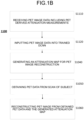
FIG. 1B illustrates a flow chart for the attenuation map generation method according to another embodiment of the present disclosure. -
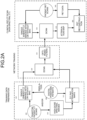
FIG. 2A illustrates a diagram of an embodiment of DCNN network training and operation in the attenuation map generation method. -
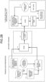
FIG. 2B illustrates a diagram of an embodiment of DCNN network training and operation in the attenuation map generation method. -
FIG. 3 illustrates a diagram of an embodiment of DCNN network training and operation in the attenuation map generation method. -
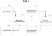
FIG. 4 illustrates a diagram of an embodiment of generating training attenuation map data. -
FIG. 5 is an illustration of a perspective view of a PET scanner, according to an exemplary embodiment of the present disclosure. -
FIG. 6 is a schematic of a PET scanner and associated hardware, according to an exemplary embodiment of the present disclosure. - In nuclear medical imaging, PET scans suffer from accuracy in attenuation estimation. In the disclosed embodiments, accuracy is improved by the use of a trained Deep Convolutional Neural Network (DCNN) Model, alternatively referred to as a "neural network" or a "DCNN model" in this disclosure.
-
FIG. 1A illustrates aflow chart 1000 of one of the disclosed methods. Specifically,FIG. 1A illustrates a flow chart of one of the disclosed methods of receiving CT image data, inputting the CT image data into a trained DCCN model, generating an attenuation map for PET image reconstruction, obtaining PET data from a scan of a subject, and reconstructing a PET image from the obtained PET data and the generated attenuation map. - In step S 1010, CT image data is received. The received CT image data can be CT data from one scan, or multiple scans performed at different times, of a subject. The multiple scans can be made at a single energy level or at multiple energy levels.
- In step S1020, beam-hardening correction can be optionally performed. Beam-hardening can be performed using beam-hardening software which can, for example, use a repetitive correcting technique. Alternately, the CT scanner can be calibrated by use of a phantom to control or correct beam-hardening artifacts like cupping or streaking.
- In step S1030, the CT image data is input into a previously trained DCCN model trained to output an attenuation map. The training of the DCNN model, as described below, can be performed with data derived from one or more CT scans, from PET-derived attenuation measurements, from high-dose spectral images of a phantom and/or from a digital phantom.
- In step S1040, the attenuation map is generated and output by the DCCN model based on the input image data.
- In step S1050, PET data is obtained from a PET scan of the subject.
- In step S1060, a PET image of the subject is reconstructed from the obtained PET data using the attenuation map generated by the DCNN.
-
FIG. 1B illustrates anotherflow chart 1100 of one of the disclosed methods. Instep S1 110, PET-derived attenuation measurements are received or acquired based on a PET scan of a subject. Specifically,FIG. 1B illustrates another flow chart of a different disclosed method comprising receiving PET image data, inputting the PET image data into a trained DCCN model, generating an attenuation map for PET image reconstruction, obtaining PET data from a scan of a subject, and reconstructing a PET image from the obtained PET data and the generated attenuation map - In step S1120, the PET-derived attenuation measurements are input into a trained DCCN model. The training of the DCNN model in this embodiment, as described below, can be performed based on data from one or more CT scans, from PET-derived attenuation measurements, from a high-dose spectral image of a phantom, and/or from a digital phantom.
- In step S1040, an attenuation map is generated and output by the trained DCCN model based on the input image data.
- In
step S 1050, the PET data is obtained from a PET scan of a subject. - In step S1060, a PET image of the subject is reconstructed from the obtained PET data and the attenuation map generated by the DCNN.
-
Fig. 2A illustrates a flow diagram of an embodiment of the disclosed method of DCNN network training and operation using a single-energy CT image (integration CT image data) as input into the DCNN model. Specifically,FIG. 2A illustrates a flow diagram of an embodiment of the disclosed method of DCNN network training using a single-energy CT image 102 (with or without beam-hardening correction) as training input and a corresponding 511keV attenuation map 112 as target output during training. Beam-hardening correction, sometimes necessary due to variations in effective X-ray energy and incorrectly assigned material type, can be used to establish signatures, and allow the neural network to capture those signatures and improve accuracy in material identification and quantification. To enhance these signatures, the neural network can alternatively take as input a CT image without beam-hardening correction, or images with beam-hardening correction, but intentionally based on wrong material assumptions. - In one embodiment, single-
energy CT images 102 along with thecorresponding target 511 keV attenuation maps 112 are input to theDCNN model 130 during training. The parameters of theDCNN model 130 are adjusted to produce aDCNN model 150 used in actual operation. - In one embodiment, a supervised deep learning model for attenuation estimation using a CT or other image as input, and optionally uses a CT configuration parameter as an additional input. The goal is to estimate a translation function that minimizes a cost function, such as, for example, the function shown in Equation (1):

DCNN model 150. The loss function, such as shown inEquation 1, allows for the training of the network. A mean square error (MSE) can be used as the loss function, or alternately, a half mean square error (HMSE), a root mean square error (RMSE), or a mean absolute error (MAE) may be used as a loss function. When fully trained, the neural network directly produces a translational function converting an input CT image into an attenuation map that can be used in PET reconstruction. In another embodiment, one can also use multiple neural network structures to attempt to minimize the loss function, and the parameters of those networks will form the trained network to be used with a new pair of images. - As shown in
FIG. 2A , the initial single-energy CT image 102 can be produced by using aphantom scan 106. In another embodiment, the image can be produced by adigital phantom simulation 108 or theCT image 102 can be produced by a combination of aphantom scan 106 and a digital phantom simulation. For example, GATE (Geant4 Application Tomography Emission) software packages or the like may be used to generate a digital phantom. In combination with high-dosespectral images 110, the phantom or digital simulation images can be used to create a more accurate 511keV attenuation map 112 to be used for training. In still other embodiments, CT configurations can be changed, such as by changing the kVp, changing the scan duration settings, or optimizing collimator settings by use of a collimator setting optimization algorithm. - In one embodiment, the accurate
training attenuation map 112 can be created using generalized spectral CT protocols and material decomposition. The 511 keV attenuation map is then used with the original single-energy CT image 102 to train theDCNN model 130. Once the DCNN training is completed, optimizedfilters 132 are used to produce aDCNN model 150 to be used in a clinical setting. TheDCNN model 150 is then used to produce anattenuation map 170 from an input single-energy CT scan obtained from a patient scan using, e.g., a PET/CT scanner apparatus, which also producesPET data 160 used in thePET reconstruction 180. -
FIG. 2B illustrates a flow diagram of another embodiment using PET-derived attenuation measurements that act as inputs into the DCNN model. In this embodiment, the input to the neural network to generate the 512 keV attenuation map is the PET-derivedattenuation measurement 214 obtained, for example, using a process of simultaneous, model-based estimation of emission and attenuation from the PET data. See Li Y, Matej S, Karp JS. Practical joint reconstruction of activity and attenuation with autonomous scaling for time-of-flight PET. Phys Med Biol. 2020, Dec 23, which is incorporated herein by reference. - A monoenergetic or multi-energetic, source-based transmission scan can be used in this embodiment. Traditionally, Ge-68 or Cs-137 is used for transmission scanning because they are mono-energetic and close to the 511 keV of PET annihilation photons. This embodiment can also enable lower energy sources, e.g., Co-57, to be used for reasons of cost or safety. A Lu-176 transmission scan of the object can also be used with a low-rate background gammas from a Lubased detector.
- In other embodiments, this same principal can be extended to provide input images to a DCNN model that are obtained from images different from CT. For example, SPECT data can be used as input to the DCNN training model. Further, the input to the DCNN model can come from a Magnetic Resonance (MR) image. Various MR sequences, such as MRS, can also be used to strengthen the specificity of the DCNN model.
- When input images to the DCNN model come from a source different from CT, the alignment between the input images and the target attenuation maps generated from spectral CT protocols needs to be well aligned. Special phantoms, with well-known material properties and marking structures, as recognized in both input images and target attenuation maps, can be used to mitigate the mis-alignment issue. Simulations with digital phantoms can also be used to provide both the input images and target attenuation maps for training the DCNN model.
-
FIG. 3 illustrates a flow diagram of another embodiment using multiple single-energy CT images as input into the DCNN model. In this embodiment, single-energy CT images with beam-hardeningcorrection 104 and without beam-hardeningcorrection 102 are both input to the DCNN model during training. The two or more CT images can, for example, include different types of beam-hardening correction (one material, two-material) or may include beam-hardening correction, but (intentionally) based on wrong material assumption to improve the signature of artifacts and thereby improve the DCNN.FIG. 3 further illustrates the subject CT images without beam-hardeningcorrection 242 and the subject CT images with beam-hardening correction 244 as input to the trainedDCCN 150. -
FIG. 4 illustrates a flow diagram of using at least two different scans to generate a 511 keV attenuation map using material decomposition. Specifically,FIG. 4 illustrates a flow diagram of a general rotate-rotate spectral CT protocol which uses at least two different kVp scans to generate a 511keV attenuation map 112.FIG. 4 illustrates an80kVp scan 402 and a 135 kVp scan 404. These low and high energy scans are used by material decomposition processes to produce two differentbasis material images attenuation map 112 can be calculated directly based on material information in the digital phantom/patient. - The proposed methods of this disclosure can either produce multiple trained networks to accommodate variations in system design or scan protocols, or the methods can be used to produce a common network with additional input of system configuration or scan protocols for general use. The neural network can also be combined with other advanced imaging processing networks for further dose reduction and reduction of artifacts.
- In one embodiment, it can be appreciated that the methods of the present disclosure are implemented within a PET scanner, as shown in
FIG. 5 andFIG. 6 .FIG. 5 andFIG. 6 show aPET scanner 8000 including a number of gamma-ray detectors (GRDs) 8001, 8002...8040 (e.g., GRD1, GRD2, through GRDN) that are each configured as rectangular detector modules. ThePET scanner 8000 may be an adaptive axial Field of View (aaFOV) PET scanner, as introduced above. According to one implementation, each PET detector ring, which forms acylindrical bore 8050 about agantry 8060 includes, for example, 40 GRDs. In another implementation, there are 48 or more GRDs, the higher number of GRDs being used to create a larger bore size for thePET scanner 8000. As in the present disclosure, each PET detector ring may be independently translatable about an axial length of the aaFOV PET scanner. The translation of each PET detector ring may be accomplished by manual manipulation and/or motorized manipulation. The GRDs include scintillator crystal arrays for converting the gamma rays into scintillation photons (e.g., at optical, infrared, and ultraviolet wavelengths), which are detected by photodetectors. Each GRD can include a two-dimensional array of individual detector crystals, which absorb gamma radiation and emit scintillation photons. The scintillation photons can be detected by a two-dimensional array of photomultiplier tubes (PMTs) that are also arranged in the GRD. A light guide can be disposed between the array of detector crystals and the PMTs. Further, each GRD can include a number of PMTs of various sizes, each of which is arranged to receive scintillation photons from a plurality of detector crystals. Each PMT can produce an analog signal that indicates when scintillation events occur, and an energy of the gamma ray producing the detection event. Moreover, the photons emitted from one detector crystal can be detected by more than one PMT, and, based on the analog signal produced at each PMT, the detector crystal corresponding to the detection event can be determined using Anger logic and crystal decoding, for example. However, Anger arithmetic is not necessarily required when there is a one-to-one correspondence between the crystals and the photodetectors. -
FIG. 6 shows a schematic view of a PET scannersystem having GRDs FIG. 5 andFIG. 6 , and as described herein. It can be appreciated that the single PET detector ring ofFIG. 6 can be extrapolated to include any number of PET detector rings along an axial length of the PET scanner. The detector crystals can be scintillator crystals, which have individual scintillator elements arranged in a two-dimensional array and the scintillator elements can be any known scintillating material. The PMTs can be arranged such that light from each scintillator element is detected by multiple PMTs to enable Anger arithmetic and crystal decoding of scintillation event. -
FIG. 6 shows an example of the arrangement of thePET scanner 8000, in which an object, such as the subject or patient to be imaged, rests on a table 9160 and theGRD modules GRD1 8001 throughGRDN 8040 are arranged circumferentially around the object OBJ and the table 9160. The GRDs may comprise a PET detector ring and may be fixedly-connected to acylindrical bore 8050 that is fixedly-connected to agantry 8060. Thegantry 8060 houses many parts of the PET scanner. Thegantry 8060 of the PET scanner also includes an open aperture, defined by thecylindrical bore 8050, through which the object OBJ and the table 9160 can pass, and gamma-rays emitted in opposite directions from the object OBJ due to an annihilation event can be detected by the GRDs and timing and energy information can be used to determine coincidences for gamma-ray pairs. - In
FIG. 6 , circuitry and hardware is also shown for acquiring, storing, processing, and distributing gamma-ray detection data. The circuitry and hardware include aprocessor 9070, anetwork controller 9074, amemory 9078, theDCNN model 9080 stored within the memory and a data acquisition system (DAS) 9076. The PET imager also includes a data channel that routes detection measurement results from the GRDs to theDAS 9076, theprocessor 9070, thememory 9078, and thenetwork controller 9074. TheDAS 9076 can control the acquisition, digitization, and routing of the detection data from the detectors. In one implementation, theDAS 9076 controls the movement of the table 9160. Theprocessor 9070 performs functions including adjusting PET detector rings, pre-reconstruction processing of the detection data, image reconstruction, and post-reconstruction processing of the image data. Theprocessor 9070 is processing circuitry and performs a receiving function corresponding to receiving unit, a generating function corresponding to generating unit, and a reconstructing function corresponding to reconstructing unit. ThePET scanner 8000 is an example of apparatus including the medical image processing apparatus according to the present application. - According to an embodiment, the
processor 9070 of thePET scanner 8000 ofFIG. 5 andFIG. 6 can be configured to perform any of the methods described herein, as well as variations thereof. - According to another embodiment, there may be fewer number of GRD modules, such as, for example, a single module.
- As shown in
FIG. 5 , theprocessor 9070 can include a CPU that can be implemented as discrete logic gates, as an Application Specific Integrated Circuit (ASIC), a Field Programmable Gate Array (FPGA) or another Complex Programmable Logic Device (CPLD). An FPGA or CPLD implementation may be coded in VHDL, Verilog, or any other hardware description language and the code may be stored in an electronic memory directly within the FPGA or CPLD, or as a separate electronic memory. Further, thememory 9078 can be a hard disk drive, CD-ROM drive, DVD drive, FLASH drive, RAM, ROM, or any other electronic storage known in the art. Thememory 9078 may be non-volatile, such as ROM, EPROM, EEPROM or FLASH memory. Thememory 9078 can also be volatile, such as static or dynamic RAM, and a processor, such as a microcontroller or microprocessor, may be provided to manage the electronic memory as well as the interaction between the FPGA or CPLD and the memory. - Alternatively, the CPU in the
processor 9070 can execute a computer program including a set of non-transitory computer-readable instructions that perform the methods described herein, the program being stored in any of the above-described non-transitory computer-readable medium including electronic memories and/or a hard disk drive, CD, DVD, FLASH drive or any other known storage media. Further, the computer-readable instructions may be provided as a utility application, background daemon, or component of an operating system, or combination thereof, executing in conjunction with a processor, such as a XENON® processor from Intel of America or an OPTERON® processor from AMD of America and an operating system, such as Microsoft VISTA®, UNIX, Solaris®, LINUX, Apple MAC-OS® and other operating systems known to those skilled in the art. Further, CPU can be implemented as multiple processors locally or in a distributed cloud configuration cooperatively working in parallel to perform the instructions stored in amemory 9078 and implementing theDCNN model 9080 wherein thememory 9078 andDCNN model 9080 may be stored locally or in the distributed cloud configuration. - In one implementation, the PET scanner may include a display for displaying a reconstructed image and the like. The display can be an LCD display, CRT display, plasma display, OLED, LED, or any other display known in the art.
- The
network controller 9074, such as an Intel Ethernet PRO network interface card from Intel Corporation of America, can interface between the various parts of the PET imager. Additionally, thenetwork controller 9074 can also interface with an external network. As can be appreciated, the external network can be a public network, such as the Internet, or a private network such as an LAN or WAN network, or any combination thereof and can also include PSTN or ISDN sub-networks. The external network can also be wired, such as an Ethernet network, or can be wireless such as a cellular network including GPRS, EDGE, 3G, 4G and 5G wireless cellular systems. The wireless network can also be Wi-Fi, Bluetooth, or any other wireless form of communication that is known. - Obviously, numerous modifications and variations are possible in light of the above teachings. It is therefore to be understood that within the scope of the appended claims, the invention may be practiced otherwise than as specifically described herein.
- The method and system described herein can be implemented in a number of technologies but generally relate to imaging devices and/or processing circuitry for performing the processes described herein. In an embodiment in which neural networks are used, the processing circuitry used to train the neural network(s) need not be the same as the processing circuitry used to implement the trained neural network(s) that perform(s) the methods described herein. For example, an FPGA may be used to produce a trained neural network (e.g. as defined by its interconnections and weights), and the
processor 9070 andmemory 9078 can be used to implement the trained neural network. Moreover, the training and use of a trained neural network may use a serial implementation or a parallel implementation for increased performance (e.g., by implementing the trained neural network on a parallel processor architecture such as a graphics processor architecture). - In the preceding description, specific details have been set forth. It should be understood, however, that techniques herein may be practiced in other embodiments that depart from these specific details, and that such details are for purposes of explanation and not limitation. Embodiments disclosed herein have been described with reference to the accompanying drawings. Similarly, for purposes of explanation, specific numbers, materials, and configurations have been set forth in order to provide a thorough understanding. Nevertheless, embodiments may be practiced without such specific details. Components having substantially the same functional constructions are denoted by like reference characters, and thus any redundant descriptions may be omitted.
- Various techniques have been described as multiple discrete operations to assist in understanding the various embodiments. The order of description should not be construed as to imply that these operations are necessarily order dependent. Indeed, these operations need not be performed in the order of presentation. Operations described may be performed in a different order than the described embodiment. Various additional operations may be performed and/or described operations may be omitted in additional embodiments.
- As described above, according to an embodiment, it is possible to improve the accuracy of the attenuation map used for attenuation correction of PET images.
- Those skilled in the art will also understand that there can be many variations made to the operations of the techniques explained above while still achieving the same objectives of the invention. Such variations are intended to be covered by the scope of this disclosure. As such, the foregoing descriptions of embodiments of the invention are not intended to be limiting. Rather, any limitations to embodiments of the invention are presented in the following claims.
Claims (17)
- An attenuation map generation method, comprising:receiving computed tomography (CT) image data of a subject; andgenerating an attenuation map for Positron Emission Tomography (PET) image reconstruction by inputting the received CT image data into a trained deep convolutional neural network (DCNN) model that outputs the attenuation map, wherein the DCNN model was trained using training input image data and corresponding training attenuation map data generated from spectral CT image data.
- The attenuation map generation method according to claim 1, wherein the receiving step comprises receiving integration CT image data.
- The attenuation map generation method according to claim 1 or 2, further comprising:obtaining PET data from a scan of a subject; andreconstructing a PET image from the obtained PET data and the generated attenuation map.
- The attenuation map generation method according to any one of claims 1 to 3, further comprising obtaining the training attenuation map data from input image data obtained from a first CT scan having a first energy below 90 kVp and from a second CT scan having an energy above 125 kVp.
- The attenuation map generation method according to claim 4, further comprising:generating a first basis material image and a second basis material image based on the input image data, andgenerating the attenuation map from the first and second basis material images.
- The attenuation map generation method according to any one of claims 1 to 5, further comprising obtaining the training attenuation map data from input image data, which is produced by a spectral CT scan.
- The attenuation map generation method according to any one of claims 1 to 6, further comprising obtaining the training attenuation map data from input image data, which is obtained from a fast kV switching dual-energy CT scan.
- The attenuation map generation method according to any one of claims 1 to 7, further comprising obtaining the training attenuation map data from input image data, which is obtained from a scan using a photon-counting CT apparatus.
- The attenuation map generation method according to any one of claims 1 to 8, further comprising obtaining the training attenuation map data from input image data, which is obtained from a simulation or from a digital phantom.
- The attenuation map generation method according to any one of claims 1 to 9, wherein the received CT image data was generated with beam-hardening correction turned off.
- The attenuation map generation method according to claim 1, further comprising correcting the received CT image data using a beam-hardening correction process prior to inputting the CT image data into the trained DCNN model.
- The attenuation map generation method according to any one of claims 1 to 11, wherein the received CT image data includes both integration CT image data having been beam-hardening corrected and integration CT image data not having been beam-hardening corrected.
- The attenuation map generation method according to any one of claims 1 to 12, further comprising training the DCNN model by minimizing a loss function.
- A medical image processing apparatus (8000), comprising:a receiving unit (9070) configured to receive computed tomography (CT) image data of a subject; anda generating unit (9070) configured to generate an attenuation map for Positron Emission Tomography (PET) image reconstruction by inputting the received CT image data to a trained deep convolutional neural network (DCNN) model that outputs the attenuation map, wherein the DCNN model is trained using training image data and corresponding training data from spectral CT image data.
- The medical image processing apparatus (8000) according to claim 14, wherein the receiving unit (9070) is further configured to receive, as the CT image data, integration CT image data.
- The medical image processing apparatus (8000) according to claim 14, further comprising:a receiving unit (9070) configured to receive PET data of the subject; anda reconstructing unit (9070) configured to reconstruct a PET image from the received PET data and the generated attenuation map.
- The medical image processing apparatus (8000) according to claim 14, wherein the receiving unit (9070) is further configured to receive the training attenuation map data from the input image data, which is one of data produced by a spectral CT scan, data obtained from a fast kV switching dual-energy CT scan, data obtained with a scan using a photon-counting CT apparatus, and data obtained from simulation or a digital phantom.
Applications Claiming Priority (2)
| Application Number | Priority Date | Filing Date | Title |
|---|---|---|---|
| US18/151,497 US20240233213A1 (en) | 2023-01-09 | 2023-01-09 | Training of neural network for attenuation correction in pet/ct |
| JP2023213407A JP2024098144A (en) | 2023-01-09 | 2023-12-18 | Attenuation map generating method and medical image processing device |
Publications (2)
| Publication Number | Publication Date |
|---|---|
| EP4397246A1 true EP4397246A1 (en) | 2024-07-10 |
| EP4397246B1 EP4397246B1 (en) | 2025-08-13 |
Family
ID=89542211
Family Applications (1)
| Application Number | Title | Priority Date | Filing Date |
|---|---|---|---|
| EP24150922.3A Active EP4397246B1 (en) | 2023-01-09 | 2024-01-09 | Attenuation map generation method and medical image processing apparatus |
Country Status (1)
| Country | Link |
|---|---|
| EP (1) | EP4397246B1 (en) |
Citations (3)
| Publication number | Priority date | Publication date | Assignee | Title |
|---|---|---|---|---|
| US6950494B2 (en) | 2003-09-11 | 2005-09-27 | Siemens Medical Solutions, Usa | Method for converting CT data to linear attenuation coefficient map data |
| US20210093266A1 (en) * | 2019-09-30 | 2021-04-01 | Siemens Healthcare Gmbh | Spectral ct-based 511 kev for positron emission tomography |
| US20220395244A1 (en) * | 2019-09-30 | 2022-12-15 | Siemens Healthcare Gmbh | Method and data processing system for providing a stroke information |
-
2024
- 2024-01-09 EP EP24150922.3A patent/EP4397246B1/en active Active
Patent Citations (3)
| Publication number | Priority date | Publication date | Assignee | Title |
|---|---|---|---|---|
| US6950494B2 (en) | 2003-09-11 | 2005-09-27 | Siemens Medical Solutions, Usa | Method for converting CT data to linear attenuation coefficient map data |
| US20210093266A1 (en) * | 2019-09-30 | 2021-04-01 | Siemens Healthcare Gmbh | Spectral ct-based 511 kev for positron emission tomography |
| US20220395244A1 (en) * | 2019-09-30 | 2022-12-15 | Siemens Healthcare Gmbh | Method and data processing system for providing a stroke information |
Non-Patent Citations (3)
| Title |
|---|
| CHUANYONG BAILING SHAO, A. J.DA SILVAZUO ZHAO: "A generalized model for the conversion from CT numbers to linear attenuation coefficients", IEEE TRANSACTIONS ON NUCLEAR SCIENCE, vol. 50, no. 5, October 2003 (2003-10-01), pages 1510 - 1515, XP011102305, DOI: 10.1109/TNS.2003.817281 |
| CROXFORD ET AL., JOURNAL OF NUCLEAR MEDICINE, May 2010 (2010-05-01) |
| LI YMATEJ SKARP JS: "Practical joint reconstruction of activity and attenuation with autonomous scaling for time-of-flight PET", PHYS MED BIOL., 23 December 2020 (2020-12-23) |
Also Published As
| Publication number | Publication date |
|---|---|
| EP4397246B1 (en) | 2025-08-13 |
Similar Documents
| Publication | Publication Date | Title |
|---|---|---|
| US20240233213A1 (en) | Training of neural network for attenuation correction in pet/ct | |
| Livieratos | Technical pitfalls and limitations of SPECT/CT | |
| US10499869B2 (en) | Apparatus and method for material decomposition of spectrally resolved projection data using singles counts | |
| US10743830B2 (en) | Method and apparatus for scatter correction in position emission tomography (PET) imaging by performing a short PET scan in an extended region to estimate scatter coming from outside of the field of view (FOV) | |
| Lin et al. | An efficient polyenergetic SART (pSART) reconstruction algorithm for quantitative myocardial CT perfusion | |
| US20180061097A1 (en) | Image generation apparatus, image generation method, and x-ray ct apparatus | |
| Koyama et al. | Radiation dose evaluation in tomosynthesis and C‐arm cone‐beam CT examinations with an anthropomorphic phantom | |
| Elhamiasl et al. | Low-dose x-ray CT simulation from an available higher-dose scan | |
| US11367227B2 (en) | Method and apparatus for computer vision based attenuation map generation | |
| Rakvongthai et al. | Spectral CT using multiple balanced K-edge filters | |
| US11389127B2 (en) | Spectral CT-based 511 KeV for positron emission tomography | |
| WO2021260928A1 (en) | Absorption coefficient image generation method, nuclear medicine diagnostic device, and method for creating trained models | |
| JP2009047602A (en) | Positron emission computed tomography device, attenuation map creation device, and attenuation map creation program | |
| JP7601690B2 (en) | Medical image processing device, medical image processing method and program | |
| Bai et al. | Phantom evaluation of a cardiac SPECT/VCT system that uses a common set of solid-state detectors for both emission and transmission scans | |
| EP4397246B1 (en) | Attenuation map generation method and medical image processing apparatus | |
| US12488446B2 (en) | Apparatus and methods for unsupervised image denoising using double over-parameterization | |
| JP2023120173A (en) | Medical imaging scanner, method and program | |
| Goh et al. | Dual-energy x-ray approach for object/energy-specific attenuation coefficient correction in single-photon emission computed tomography: effects of contrast agent | |
| Blankespoor et al. | Development of an emission-transmission CT system combining x-ray CT and SPECT | |
| JP5702575B2 (en) | Radiation tomographic image processing system and radiation tomographic image processing method | |
| US20240037814A1 (en) | Convolutional neural network for dynamic pet frame clustering | |
| Wei et al. | PET/CT alignment calibration with a non-radioactive phantom and the intrinsic 176Lu radiation of PET detector | |
| EP4318400A1 (en) | Image processing apparatus, image processing method and program | |
| Lai et al. | A curve fitting approach using ann for converting ct number to linear attenuation coefficient for ct-based pet attenuation correction |
Legal Events
| Date | Code | Title | Description |
|---|---|---|---|
| PUAI | Public reference made under article 153(3) epc to a published international application that has entered the european phase |
Free format text: ORIGINAL CODE: 0009012 |
|
| STAA | Information on the status of an ep patent application or granted ep patent |
Free format text: STATUS: REQUEST FOR EXAMINATION WAS MADE |
|
| 17P | Request for examination filed |
Effective date: 20240109 |
|
| AK | Designated contracting states |
Kind code of ref document: A1 Designated state(s): AL AT BE BG CH CY CZ DE DK EE ES FI FR GB GR HR HU IE IS IT LI LT LU LV MC ME MK MT NL NO PL PT RO RS SE SI SK SM TR |
|
| GRAP | Despatch of communication of intention to grant a patent |
Free format text: ORIGINAL CODE: EPIDOSNIGR1 |
|
| STAA | Information on the status of an ep patent application or granted ep patent |
Free format text: STATUS: GRANT OF PATENT IS INTENDED |
|
| INTG | Intention to grant announced |
Effective date: 20250306 |
|
| GRAS | Grant fee paid |
Free format text: ORIGINAL CODE: EPIDOSNIGR3 |
|
| GRAA | (expected) grant |
Free format text: ORIGINAL CODE: 0009210 |
|
| STAA | Information on the status of an ep patent application or granted ep patent |
Free format text: STATUS: THE PATENT HAS BEEN GRANTED |
|
| AK | Designated contracting states |
Kind code of ref document: B1 Designated state(s): AL AT BE BG CH CY CZ DE DK EE ES FI FR GB GR HR HU IE IS IT LI LT LU LV MC ME MK MT NL NO PL PT RO RS SE SI SK SM TR |
|
| REG | Reference to a national code |
Ref country code: GB Ref legal event code: FG4D |
|
| REG | Reference to a national code |
Ref country code: CH Ref legal event code: EP |
|
| REG | Reference to a national code |
Ref country code: DE Ref legal event code: R096 Ref document number: 602024000412 Country of ref document: DE |
|
| REG | Reference to a national code |
Ref country code: IE Ref legal event code: FG4D |
|
| REG | Reference to a national code |
Ref country code: NL Ref legal event code: MP Effective date: 20250813 |
|
| PG25 | Lapsed in a contracting state [announced via postgrant information from national office to epo] |
Ref country code: IS Free format text: LAPSE BECAUSE OF FAILURE TO SUBMIT A TRANSLATION OF THE DESCRIPTION OR TO PAY THE FEE WITHIN THE PRESCRIBED TIME-LIMIT Effective date: 20251213 |
|
| PG25 | Lapsed in a contracting state [announced via postgrant information from national office to epo] |
Ref country code: NO Free format text: LAPSE BECAUSE OF FAILURE TO SUBMIT A TRANSLATION OF THE DESCRIPTION OR TO PAY THE FEE WITHIN THE PRESCRIBED TIME-LIMIT Effective date: 20251113 |
|
| REG | Reference to a national code |
Ref country code: LT Ref legal event code: MG9D |
|
| PG25 | Lapsed in a contracting state [announced via postgrant information from national office to epo] |
Ref country code: PT Free format text: LAPSE BECAUSE OF FAILURE TO SUBMIT A TRANSLATION OF THE DESCRIPTION OR TO PAY THE FEE WITHIN THE PRESCRIBED TIME-LIMIT Effective date: 20251215 |
|
| PG25 | Lapsed in a contracting state [announced via postgrant information from national office to epo] |
Ref country code: FI Free format text: LAPSE BECAUSE OF FAILURE TO SUBMIT A TRANSLATION OF THE DESCRIPTION OR TO PAY THE FEE WITHIN THE PRESCRIBED TIME-LIMIT Effective date: 20250813 |
|
| PG25 | Lapsed in a contracting state [announced via postgrant information from national office to epo] |
Ref country code: HR Free format text: LAPSE BECAUSE OF FAILURE TO SUBMIT A TRANSLATION OF THE DESCRIPTION OR TO PAY THE FEE WITHIN THE PRESCRIBED TIME-LIMIT Effective date: 20250813 Ref country code: NL Free format text: LAPSE BECAUSE OF FAILURE TO SUBMIT A TRANSLATION OF THE DESCRIPTION OR TO PAY THE FEE WITHIN THE PRESCRIBED TIME-LIMIT Effective date: 20250813 |
|
| PG25 | Lapsed in a contracting state [announced via postgrant information from national office to epo] |
Ref country code: GR Free format text: LAPSE BECAUSE OF FAILURE TO SUBMIT A TRANSLATION OF THE DESCRIPTION OR TO PAY THE FEE WITHIN THE PRESCRIBED TIME-LIMIT Effective date: 20251114 |
|
| PG25 | Lapsed in a contracting state [announced via postgrant information from national office to epo] |
Ref country code: SE Free format text: LAPSE BECAUSE OF FAILURE TO SUBMIT A TRANSLATION OF THE DESCRIPTION OR TO PAY THE FEE WITHIN THE PRESCRIBED TIME-LIMIT Effective date: 20250813 |
|
| PG25 | Lapsed in a contracting state [announced via postgrant information from national office to epo] |
Ref country code: LV Free format text: LAPSE BECAUSE OF FAILURE TO SUBMIT A TRANSLATION OF THE DESCRIPTION OR TO PAY THE FEE WITHIN THE PRESCRIBED TIME-LIMIT Effective date: 20250813 |
|
| PG25 | Lapsed in a contracting state [announced via postgrant information from national office to epo] |
Ref country code: PL Free format text: LAPSE BECAUSE OF FAILURE TO SUBMIT A TRANSLATION OF THE DESCRIPTION OR TO PAY THE FEE WITHIN THE PRESCRIBED TIME-LIMIT Effective date: 20250813 Ref country code: BG Free format text: LAPSE BECAUSE OF FAILURE TO SUBMIT A TRANSLATION OF THE DESCRIPTION OR TO PAY THE FEE WITHIN THE PRESCRIBED TIME-LIMIT Effective date: 20250813 |
|
| PG25 | Lapsed in a contracting state [announced via postgrant information from national office to epo] |
Ref country code: RS Free format text: LAPSE BECAUSE OF FAILURE TO SUBMIT A TRANSLATION OF THE DESCRIPTION OR TO PAY THE FEE WITHIN THE PRESCRIBED TIME-LIMIT Effective date: 20251113 |
|
| PG25 | Lapsed in a contracting state [announced via postgrant information from national office to epo] |
Ref country code: ES Free format text: LAPSE BECAUSE OF FAILURE TO SUBMIT A TRANSLATION OF THE DESCRIPTION OR TO PAY THE FEE WITHIN THE PRESCRIBED TIME-LIMIT Effective date: 20250813 |
|
| REG | Reference to a national code |
Ref country code: AT Ref legal event code: MK05 Ref document number: 1823806 Country of ref document: AT Kind code of ref document: T Effective date: 20250813 |
|
| PG25 | Lapsed in a contracting state [announced via postgrant information from national office to epo] |
Ref country code: SM Free format text: LAPSE BECAUSE OF FAILURE TO SUBMIT A TRANSLATION OF THE DESCRIPTION OR TO PAY THE FEE WITHIN THE PRESCRIBED TIME-LIMIT Effective date: 20250813 |
|
| PG25 | Lapsed in a contracting state [announced via postgrant information from national office to epo] |
Ref country code: DK Free format text: LAPSE BECAUSE OF FAILURE TO SUBMIT A TRANSLATION OF THE DESCRIPTION OR TO PAY THE FEE WITHIN THE PRESCRIBED TIME-LIMIT Effective date: 20250813 |
|
| PGFP | Annual fee paid to national office [announced via postgrant information from national office to epo] |
Ref country code: DE Payment date: 20251126 Year of fee payment: 3 |
|
| PG25 | Lapsed in a contracting state [announced via postgrant information from national office to epo] |
Ref country code: AT Free format text: LAPSE BECAUSE OF FAILURE TO SUBMIT A TRANSLATION OF THE DESCRIPTION OR TO PAY THE FEE WITHIN THE PRESCRIBED TIME-LIMIT Effective date: 20250813 |
|
| PG25 | Lapsed in a contracting state [announced via postgrant information from national office to epo] |
Ref country code: IT Free format text: LAPSE BECAUSE OF FAILURE TO SUBMIT A TRANSLATION OF THE DESCRIPTION OR TO PAY THE FEE WITHIN THE PRESCRIBED TIME-LIMIT Effective date: 20250813 |
|
| PG25 | Lapsed in a contracting state [announced via postgrant information from national office to epo] |
Ref country code: CZ Free format text: LAPSE BECAUSE OF FAILURE TO SUBMIT A TRANSLATION OF THE DESCRIPTION OR TO PAY THE FEE WITHIN THE PRESCRIBED TIME-LIMIT Effective date: 20250813 |
|
| PG25 | Lapsed in a contracting state [announced via postgrant information from national office to epo] |
Ref country code: SK Free format text: LAPSE BECAUSE OF FAILURE TO SUBMIT A TRANSLATION OF THE DESCRIPTION OR TO PAY THE FEE WITHIN THE PRESCRIBED TIME-LIMIT Effective date: 20250813 Ref country code: EE Free format text: LAPSE BECAUSE OF FAILURE TO SUBMIT A TRANSLATION OF THE DESCRIPTION OR TO PAY THE FEE WITHIN THE PRESCRIBED TIME-LIMIT Effective date: 20250813 |