EP4396052B1 - Betriebssichere parkbremsventileinheit mit einem bypassventil - Google Patents
Betriebssichere parkbremsventileinheit mit einem bypassventil Download PDFInfo
- Publication number
- EP4396052B1 EP4396052B1 EP22765853.1A EP22765853A EP4396052B1 EP 4396052 B1 EP4396052 B1 EP 4396052B1 EP 22765853 A EP22765853 A EP 22765853A EP 4396052 B1 EP4396052 B1 EP 4396052B1
- Authority
- EP
- European Patent Office
- Prior art keywords
- valve
- parking brake
- connection
- brake
- unit
- Prior art date
- Legal status (The legal status is an assumption and is not a legal conclusion. Google has not performed a legal analysis and makes no representation as to the accuracy of the status listed.)
- Active
Links
Images




Classifications
-
- B—PERFORMING OPERATIONS; TRANSPORTING
- B60—VEHICLES IN GENERAL
- B60T—VEHICLE BRAKE CONTROL SYSTEMS OR PARTS THEREOF; BRAKE CONTROL SYSTEMS OR PARTS THEREOF, IN GENERAL; ARRANGEMENT OF BRAKING ELEMENTS ON VEHICLES IN GENERAL; PORTABLE DEVICES FOR PREVENTING UNWANTED MOVEMENT OF VEHICLES; VEHICLE MODIFICATIONS TO FACILITATE COOLING OF BRAKES
- B60T13/00—Transmitting braking action from initiating means to ultimate brake actuator with power assistance or drive; Brake systems incorporating such transmitting means, e.g. air-pressure brake systems
- B60T13/10—Transmitting braking action from initiating means to ultimate brake actuator with power assistance or drive; Brake systems incorporating such transmitting means, e.g. air-pressure brake systems with fluid assistance, drive, or release
- B60T13/66—Electrical control in fluid-pressure brake systems
- B60T13/68—Electrical control in fluid-pressure brake systems by electrically-controlled valves
- B60T13/683—Electrical control in fluid-pressure brake systems by electrically-controlled valves in pneumatic systems or parts thereof
-
- B—PERFORMING OPERATIONS; TRANSPORTING
- B60—VEHICLES IN GENERAL
- B60T—VEHICLE BRAKE CONTROL SYSTEMS OR PARTS THEREOF; BRAKE CONTROL SYSTEMS OR PARTS THEREOF, IN GENERAL; ARRANGEMENT OF BRAKING ELEMENTS ON VEHICLES IN GENERAL; PORTABLE DEVICES FOR PREVENTING UNWANTED MOVEMENT OF VEHICLES; VEHICLE MODIFICATIONS TO FACILITATE COOLING OF BRAKES
- B60T13/00—Transmitting braking action from initiating means to ultimate brake actuator with power assistance or drive; Brake systems incorporating such transmitting means, e.g. air-pressure brake systems
- B60T13/10—Transmitting braking action from initiating means to ultimate brake actuator with power assistance or drive; Brake systems incorporating such transmitting means, e.g. air-pressure brake systems with fluid assistance, drive, or release
- B60T13/24—Transmitting braking action from initiating means to ultimate brake actuator with power assistance or drive; Brake systems incorporating such transmitting means, e.g. air-pressure brake systems with fluid assistance, drive, or release the fluid being gaseous
- B60T13/26—Compressed-air systems
- B60T13/268—Compressed-air systems using accumulators or reservoirs
-
- B—PERFORMING OPERATIONS; TRANSPORTING
- B60—VEHICLES IN GENERAL
- B60T—VEHICLE BRAKE CONTROL SYSTEMS OR PARTS THEREOF; BRAKE CONTROL SYSTEMS OR PARTS THEREOF, IN GENERAL; ARRANGEMENT OF BRAKING ELEMENTS ON VEHICLES IN GENERAL; PORTABLE DEVICES FOR PREVENTING UNWANTED MOVEMENT OF VEHICLES; VEHICLE MODIFICATIONS TO FACILITATE COOLING OF BRAKES
- B60T13/00—Transmitting braking action from initiating means to ultimate brake actuator with power assistance or drive; Brake systems incorporating such transmitting means, e.g. air-pressure brake systems
- B60T13/10—Transmitting braking action from initiating means to ultimate brake actuator with power assistance or drive; Brake systems incorporating such transmitting means, e.g. air-pressure brake systems with fluid assistance, drive, or release
- B60T13/24—Transmitting braking action from initiating means to ultimate brake actuator with power assistance or drive; Brake systems incorporating such transmitting means, e.g. air-pressure brake systems with fluid assistance, drive, or release the fluid being gaseous
- B60T13/26—Compressed-air systems
- B60T13/38—Brakes applied by springs or weights and released by compressed air
- B60T13/385—Control arrangements therefor
-
- B—PERFORMING OPERATIONS; TRANSPORTING
- B60—VEHICLES IN GENERAL
- B60T—VEHICLE BRAKE CONTROL SYSTEMS OR PARTS THEREOF; BRAKE CONTROL SYSTEMS OR PARTS THEREOF, IN GENERAL; ARRANGEMENT OF BRAKING ELEMENTS ON VEHICLES IN GENERAL; PORTABLE DEVICES FOR PREVENTING UNWANTED MOVEMENT OF VEHICLES; VEHICLE MODIFICATIONS TO FACILITATE COOLING OF BRAKES
- B60T13/00—Transmitting braking action from initiating means to ultimate brake actuator with power assistance or drive; Brake systems incorporating such transmitting means, e.g. air-pressure brake systems
- B60T13/10—Transmitting braking action from initiating means to ultimate brake actuator with power assistance or drive; Brake systems incorporating such transmitting means, e.g. air-pressure brake systems with fluid assistance, drive, or release
- B60T13/58—Combined or convertible systems
-
- B—PERFORMING OPERATIONS; TRANSPORTING
- B60—VEHICLES IN GENERAL
- B60T—VEHICLE BRAKE CONTROL SYSTEMS OR PARTS THEREOF; BRAKE CONTROL SYSTEMS OR PARTS THEREOF, IN GENERAL; ARRANGEMENT OF BRAKING ELEMENTS ON VEHICLES IN GENERAL; PORTABLE DEVICES FOR PREVENTING UNWANTED MOVEMENT OF VEHICLES; VEHICLE MODIFICATIONS TO FACILITATE COOLING OF BRAKES
- B60T17/00—Component parts, details, or accessories of power brake systems not covered by groups B60T8/00, B60T13/00 or B60T15/00, or presenting other characteristic features
- B60T17/18—Safety devices; Monitoring
- B60T17/22—Devices for monitoring or checking brake systems; Signal devices
-
- B—PERFORMING OPERATIONS; TRANSPORTING
- B60—VEHICLES IN GENERAL
- B60T—VEHICLE BRAKE CONTROL SYSTEMS OR PARTS THEREOF; BRAKE CONTROL SYSTEMS OR PARTS THEREOF, IN GENERAL; ARRANGEMENT OF BRAKING ELEMENTS ON VEHICLES IN GENERAL; PORTABLE DEVICES FOR PREVENTING UNWANTED MOVEMENT OF VEHICLES; VEHICLE MODIFICATIONS TO FACILITATE COOLING OF BRAKES
- B60T8/00—Arrangements for adjusting wheel-braking force to meet varying vehicular or ground-surface conditions, e.g. limiting or varying distribution of braking force
- B60T8/17—Using electrical or electronic regulation means to control braking
- B60T8/171—Detecting parameters used in the regulation; Measuring values used in the regulation
-
- B—PERFORMING OPERATIONS; TRANSPORTING
- B60—VEHICLES IN GENERAL
- B60T—VEHICLE BRAKE CONTROL SYSTEMS OR PARTS THEREOF; BRAKE CONTROL SYSTEMS OR PARTS THEREOF, IN GENERAL; ARRANGEMENT OF BRAKING ELEMENTS ON VEHICLES IN GENERAL; PORTABLE DEVICES FOR PREVENTING UNWANTED MOVEMENT OF VEHICLES; VEHICLE MODIFICATIONS TO FACILITATE COOLING OF BRAKES
- B60T2270/00—Further aspects of brake control systems not otherwise provided for
- B60T2270/40—Failsafe aspects of brake control systems
- B60T2270/402—Back-up
-
- B—PERFORMING OPERATIONS; TRANSPORTING
- B60—VEHICLES IN GENERAL
- B60T—VEHICLE BRAKE CONTROL SYSTEMS OR PARTS THEREOF; BRAKE CONTROL SYSTEMS OR PARTS THEREOF, IN GENERAL; ARRANGEMENT OF BRAKING ELEMENTS ON VEHICLES IN GENERAL; PORTABLE DEVICES FOR PREVENTING UNWANTED MOVEMENT OF VEHICLES; VEHICLE MODIFICATIONS TO FACILITATE COOLING OF BRAKES
- B60T2270/00—Further aspects of brake control systems not otherwise provided for
- B60T2270/40—Failsafe aspects of brake control systems
- B60T2270/406—Test-mode; Self-diagnosis
-
- B—PERFORMING OPERATIONS; TRANSPORTING
- B60—VEHICLES IN GENERAL
- B60T—VEHICLE BRAKE CONTROL SYSTEMS OR PARTS THEREOF; BRAKE CONTROL SYSTEMS OR PARTS THEREOF, IN GENERAL; ARRANGEMENT OF BRAKING ELEMENTS ON VEHICLES IN GENERAL; PORTABLE DEVICES FOR PREVENTING UNWANTED MOVEMENT OF VEHICLES; VEHICLE MODIFICATIONS TO FACILITATE COOLING OF BRAKES
- B60T2270/00—Further aspects of brake control systems not otherwise provided for
- B60T2270/40—Failsafe aspects of brake control systems
- B60T2270/413—Plausibility monitoring, cross check, redundancy
-
- B—PERFORMING OPERATIONS; TRANSPORTING
- B60—VEHICLES IN GENERAL
- B60T—VEHICLE BRAKE CONTROL SYSTEMS OR PARTS THEREOF; BRAKE CONTROL SYSTEMS OR PARTS THEREOF, IN GENERAL; ARRANGEMENT OF BRAKING ELEMENTS ON VEHICLES IN GENERAL; PORTABLE DEVICES FOR PREVENTING UNWANTED MOVEMENT OF VEHICLES; VEHICLE MODIFICATIONS TO FACILITATE COOLING OF BRAKES
- B60T2270/00—Further aspects of brake control systems not otherwise provided for
- B60T2270/40—Failsafe aspects of brake control systems
- B60T2270/414—Power supply failure
Definitions
- the invention relates to an electropneumatic parking brake device for ventilating and venting one or more spring-loaded cylinders of an electronically controllable pneumatic braking system for a vehicle, comprising a parking brake valve unit with a supply connection for receiving supply pressure from a parking brake supply, wherein the parking brake valve unit controls a parking brake pressure at at least one spring-loaded connection as a function of a parking brake signal, and a check valve arranged between the parking brake valve unit and the parking brake supply (26) to prevent a backflow of compressed air from the parking brake valve unit to the parking brake supply.
- the invention further relates to an electronically controllable pneumatic braking system for a vehicle, comprising at least one first front axle brake actuator and one second front axle brake actuator on a front axle of the vehicle and at least one first rear axle brake actuator and one second rear axle brake actuator on a rear axle of the vehicle, as well as a primary system with a primary control unit at least for controlling the first front axle brake actuator, the second front axle brake actuator, the first rear axle brake actuator and the second rear axle brake actuator.
- the invention further relates to a method for controlling an electronically controllable pneumatic brake system, comprising the steps of: controlling a parking brake valve unit by means of a parking brake control unit for venting and venting at least one spring brake cylinder on a rear axle of a commercial vehicle, wherein the parking brake valve unit is connected to a parking brake reservoir via a check valve and receives reservoir pressure therefrom; and detecting a fault in the electronically controllable pneumatic brake system, in particular the parking brake control unit or parking brake valve unit.
- a solution to ventilate such spring brake cylinders is DE 10 2017 005 757 A1
- the solution disclosed therein uses a pilot valve unit and a main valve unit, wherein the pilot valve unit comprises an electromagnetic solenoid valve in the form of a bistable valve.
- the main valve unit in the solution disclosed therein is formed by a relay valve.
- a control pressure is controlled at the main valve unit, which then correspondingly controls a volume pressure for the spring brake cylinders.
- a bistable valve is a solenoid valve that has two stable switching positions, in particular a stable ventilation position and a stable venting position.
- an armature of the solenoid valve can be moved to a first position, so that the solenoid valve assumes the ventilation position, and by energizing a second electromagnet, the armature of the solenoid valve can be moved to a second position, so that the solenoid valve assumes the venting position. If no other force then acts on the armature, or if it can be mechanically and/or magnetically locked in the positions, the respective Switch position stable because it can be maintained without further power supply.
- a braking system with an additional parking brake device of the same type is DE 103 36 611 A1 It discloses a pressure-medium-operated braking system for a vehicle with a parking brake function, in which, as a result of manual actuation of an electric parking brake signal transmitter, at least one wheel brake of the braking system can be actuated via an actuator pressurized with the pressure medium without actuating a brake pedal. Based on this, a pressure-medium-operated braking system for a vehicle is specified in which a parking brake function actuated via an electric signal transmitter can be integrated with little effort while complying with the relevant safety regulations for braking systems.
- a parking brake module into which an electronic control device and a valve device electrically actuated by the electronic control device are integrated.
- the electronic control device activates the parking brake function upon receipt of an electrical actuation signal from the parking brake signal transmitter requesting activation of the parking brake function.
- the electronic control device controls the pressure application to the actuator by means of the electrically actuated valve device within the framework of the parking brake function.
- DE 10 2008 007 877 B3 a parking brake device for motor vehicles with a spring-loaded brake cylinder controllable by a relay valve, wherein the relay valve is controllable via a safety valve designed as a 3/2-way valve, the output of which is selectively connectable to one of two inputs, wherein the inputs of the safety valve are connectable via a first or a second solenoid valve, selectively to a pressure medium source or atmospheric pressure, and wherein a select-low valve is connected to one input and the output of the safety valve and an output of the select-low valve is connected to a control input of the relay valve This is intended to improve the stability of the system.
- a parking brake module with which a pressure medium application to at least one brake actuator can be controlled, wherein the parking brake module has an electronic control device, at least one solenoid valve actuatable by the control device, a pressure medium quantity amplifying valve for pressurizing the at least one brake actuator and at least one pressure medium inlet via which pressure medium can be supplied to the parking brake module.
- the parking brake module has an emergency release pressure medium connection and a double check valve.
- the parking brake module has a first pressure medium line, with which the emergency release pressure medium connection is fluidically connected via a check valve to the supply inlet of the pressure-medium-increasing valve in such a way that pressure medium flows through this first pressure medium line from the emergency release pressure medium connection to the pressure-medium-increasing valve if the pressure at the emergency release pressure medium connection is greater than the pressure at the supply inlet of the pressure-medium-increasing valve.
- the parking brake module has a second pressure medium line, with which the emergency release pressure medium connection or another pressure medium connection of the parking brake module is fluidically connected to an inlet of the double check valve in such a way that pressure medium flows through this second pressure medium line from the emergency release pressure medium connection to the double check valve if the pressure at the emergency release pressure medium connection is greater than the pressure at the inlet of the double check valve. or that pressure medium flows through this second pressure medium line from the further pressure medium connection to the double check valve if the pressure applied to the further pressure medium connection is greater than the pressure applied to the inlet of the double check valve.
- the present invention solves the problem in an electropneumatic parking brake device of the type mentioned above in that a bypass valve is provided which can be switched to ventilate and vent the spring-loaded connection, wherein the bypass valve is controlled and switched independently of the parking brake valve unit.
- the additional bypass valve which is provided alongside the generally known parking brake valve unit, serves, in addition to the parking brake valve unit, to pressurize and/or vent the spring-loaded connection and can be controlled and switched independently of the parking brake valve unit.
- the bypass valve thus forms a bypass to the parking brake valve unit and can be switched either to pressurize and/or vent the spring-loaded connection in the event that the parking brake valve unit is not functioning or is not functioning properly, or cannot be controlled or cannot be controlled properly.
- the invention is based on the idea that the bypass valve can be controlled and switched independently of the parking brake valve unit.
- the invention offers a remedy here by providing the bypass valve, which can preferably be switched both for pressing and for venting the spring-loaded connection, independently of the parking brake valve unit.
- the bypass valve unit can be switched manually or automatically to vent the spring-loaded connection and subsequently the spring-loaded brake cylinders connected to it. In this way, emergency engagement of the spring-loaded brake cylinders is possible even if the parking brake valve unit is not functioning or is not functioning properly, or cannot be controlled or cannot be controlled correctly.
- the bypass valve can be switched to pressurize the spring-loaded connection and thus release the spring-loaded brake cylinders connected to it.
- the bypass valve can comprise one or more switchable electromagnetic valves, which can be designed more cost-effectively than valves in the parking brake valve unit.
- the bypass valve is used to vent or pressurize the spring-loaded connection only in the event of a parking brake valve unit failure and is therefore only used very rarely during vehicle operation. Its sole purpose is to enable fail-safe operation, thus providing a level of redundancy for the parking brake valve unit.
- the bypass valve is electromagnetic and can be controlled by an additional electronic control unit that is independent of the parking brake valve unit.
- the parking brake valve unit is preferably controlled by a parking brake control unit, which can be part of the electropneumatic parking brake device.
- the parking brake control unit can be integrated with the parking brake valve unit to form a module.
- the parking brake control unit can have its own intelligence or only comprise output stages that are electrically connected to a higher-level control unit.
- the additional electronic control unit that controls the bypass valve is different from the parking brake control unit.
- the additional electronic control unit is preferably a control unit already present in the electronically controllable pneumatic brake system or a control unit provided separately for the bypass valve.
- bypass valve it is particularly efficient and space-saving if a control unit already present in the electronically controllable pneumatic brake system is used to control the bypass valve. In this way, it can be ensured that in the event that the parking brake control unit has a fault, the bypass valve can still be controlled and switched by the additional control unit in order to pressurize or vent the spring-loaded connection.
- the electropneumatic parking brake device has a bypass pressure sensor for detecting the parking brake pressure applied at the spring-loaded connection, wherein the bypass pressure sensor is connected to the further electronic control unit independent of the parking brake valve unit This allows the additional electronic control unit to evaluate the pressure present at the spring-loaded connection and actuate the bypass valve accordingly. This allows for the parking brake pressure to be regulated.
- the bypass valve is monostable and can assume a blocking position as well as a passing position, wherein the bypass valve is stable in the blocking position.
- the bypass valve can be designed, for example, as a 2/2-way valve and can be switched into the blocking position under spring load. Only when energized is the bypass valve then switched to the passing position, in which the spring-loaded connection can be ventilated or vented.
- the 2/2-way valve designed as a bypass valve is preferably connected to the spring-loaded connection via a first bypass valve connection and to the parking brake supply via a second bypass valve connection, or to a supply pressure line that runs between the parking brake supply and the check valve, so that the bypass valve bypasses the check valve.
- the spring-loaded connection can be vented by switching the bypass valve to the open position, bypassing the check valve and the parking brake valve unit. If the parking brake supply is largely or completely depressurized (for example, due to pumping down) due to a fault or a fault-resolution routine, the spring-loaded connection can be connected to the then depressurized parking brake supply by switching the bypass valve to the open position, bypassing the parking brake valve unit and the check valve, so that the spring-loaded connection can be vented in this case.
- the bypass valve comprises a first bypass valve connection connected to the spring-loaded connection or to a main valve unit upstream of the spring-loaded connection and a second bypass valve connection connected to a vent.
- the bypass valve comprises a the spring-loaded connection or a main valve unit upstream of the spring-loaded connection, and a second bypass valve connection connected to the parking brake reservoir upstream of the check valve.
- the second bypass valve connection can therefore be connected either to a vent or to the parking brake reservoir. This is particularly preferred if the bypass valve is designed as a 2/2-way valve as described above. If the second bypass valve connection is only connected to the vent, the spring-loaded connection can only be vented by the bypass valve in the through position. If, on the other hand, the second bypass valve connection is connected to the parking brake reservoir, the spring-loaded connection can be vented when the parking brake reservoir has sufficient pressure and vented when the parking brake reservoir is pumped down.
- the bypass valve is designed with the parking brake valve unit as a single structural unit.
- the bypass valve can be housed with the parking brake valve unit in a modular housing or simply flanged to the parking brake valve unit or formatted with it. This is particularly advantageous because it reduces assembly effort and allows for compact components. Furthermore, interfaces between individual elements can be reduced, eliminating lines that might otherwise be prone to leakage.
- the bypass valve is directly connected to a parking brake pressure line connected downstream of the spring-loaded connection.
- This design is particularly advantageous when the bypass valve is external to the parking brake valve unit, for example, flanged to it or arranged outside a module housing, or is presented as a separate component.
- the direct connection of the bypass valve to a parking brake pressure line connected downstream of the spring-loaded connection which in turn leads to the spring-loaded brake cylinder, can lead to direct venting or ventilation. of the spring brake cylinder. It is also conceivable that the bypass valve is connected directly to the spring brake cylinder.
- the parking brake valve unit comprises a pilot valve unit and a main valve unit.
- the pilot valve unit is provided to provide a parking brake control pressure to the main valve unit, which then controls the parking brake pressure at the spring-loaded connection as a function of the received parking brake control pressure.
- the main valve unit is generally designed to be volume-intensifying and can, for example, comprise a relay valve or a pneumatically switchable main valve.
- Such designs allow for more efficient air utilization, since when the parking brake pressure varies, only the parking brake control pressure, which has a lower volume, needs to be vented, so that overall air consumption can be reduced.
- the bypass valve is preferably connected to the main valve unit, wherein the parking brake control pressure can be vented via the bypass valve.
- the bypass valve is preferably connected to the main valve unit via the same line via which the pilot valve unit is connected to the main valve unit.
- the main valve unit is preferably designed to be purely pneumatic and can therefore switch independently of a parking brake control unit and independently of a power source. In the event that the pilot valve unit is not functioning or is not functioning properly, the parking brake control pressure can be vented via the bypass valve, so that the spring-loaded connection is subsequently also vented.
- the bypass valve is connected to a bypass branch line, which branches off from a parking brake control pressure line, via which the parking brake control pressure is supplied to the main valve unit by the pilot valve unit.
- a first shuttle valve is provided in the parking brake control pressure line, which has a first shuttle valve connection connected to the pilot valve unit, a second shuttle valve port connected to an anti-compound port and a third shuttle valve port connected to the main valve unit.
- the first shuttle valve is preferably configured such that the higher pressure applied to the first shuttle valve port and the second shuttle valve port is controlled at the third shuttle valve port. This design allows either the parking brake control pressure controlled by the pilot valve unit or a pressure provided via the anti-compound port to be controlled at the main valve unit.
- Tristop cylinders which can act both as service brake cylinders and as parking brake cylinders, are connected to the spring-loaded connection. If the spring-loaded part of the Tristop cylinder is vented to activate the parking brake function, it can happen that the service brake part of the Tristop cylinder is also activated, for example if a vehicle operator presses a brake pedal. In this case, both the spring-loaded part and the service brake part would exert a force, which can lead to component overload.
- the service brake pressure applied to the Tristop cylinder is simultaneously fed to the parking brake system via the anti-compound connection, which then applies parking brake pressure to the spring-loaded connection to similarly pressurize and thus release the spring-loaded part of the Tristop cylinder.
- bypass branch line branches off between the first shuttle valve connection and the pilot valve unit.
- the bypass valve should be designed such that it can vent the parking brake control pressure, and not the anti-compound pressure that is present at the anti-compound connection. The anti-compound function therefore remains independent of the bypass valve's switching.
- the parking brake valve unit has a compensation valve, which is designed to maintain a parking brake control pressure controlled by the pilot valve unit at the main valve unit and thus at least partially compensate for a leak in the pilot valve unit and/or the main valve unit.
- the compensation valve can advantageously compensate for leaks that occur in the pilot valve unit and/or the main valve unit. This is advantageously made possible by a controllable pneumatic connection to the parking brake supply or to a vent connection, which can be established by the compensation valve.
- the compensation valve is preferably designed as a pneumatically switchable 3/2-way valve and has a first compensation valve connection connected to the check valve, a second compensation valve connection connected to a line carrying the parking brake control pressure, and a third compensation valve connection connected to a vent.
- the compensation valve is spring-loaded into a first switching position, in which the second compensation valve connection is connected to the third compensation valve connection. If a compensation valve control pressure provided at a compensation valve control connection exceeds a compensation valve threshold, the compensation valve switches to a second switching position, in which the first compensation valve connection is connected to the second compensation valve connection.
- the compensation valve control pressure is a pressure applied or controlled at the second compensation valve connection, whereby a pneumatic self-locking for the compensation valve is realized.
- the compensation valve has a return spring that preloads the compensation valve into the first switching position.
- the compensation valve is designed, in particular by designing one or the return spring, to switch to the second switching position when the Compensation valve threshold is exceeded.
- the compensation valve threshold is in a range between 0.241 MPa (35 psi) and 0.379 MPa (55 psi), preferably from 0.276 MPa (40 psi) to 0.345 MPa (50 psi), and is preferably 0.310 MPa (45 psi).
- the second compensation valve connection is pneumatically connected to the compensation valve control connection via a compensation control path.
- the compensation valve is designed to be throttled, preferably such that the connection of the first compensation valve connection to the second compensation valve connection and/or the connection of the second compensation valve connection to the third compensation valve connection is throttled in each case.
- the compensation valve has a first throttle for throttling the pneumatic connection between the first compensation valve connection and the second compensation valve connection in the second switching position.
- the second compensation valve has a second throttle for throttling the pneumatic connection between the second compensation valve connection and the third compensation valve connection in the first switching position.
- a common throttle can be provided which is independent of the switching position of the compensation valve and is connected upstream or downstream of the compensation valve.
- such a common throttle can be arranged between the second compensation valve connection and a branch node for the compensation control path.
- the parking brake valve unit and the bypass valve are supplied with electrical voltage from two independent voltage sources.
- the additional electronic control unit is also supplied by the voltage source that also supplies the bypass valve. In this way, safety can be increased and fail-safe operation can be enabled in a braking system that has two independent voltage sources.
- the invention achieves the object mentioned at the outset in an electronically controllable pneumatic braking system in that it has an electropneumatic parking brake device according to one of the above-described preferred embodiments of an electropneumatic parking brake device according to the first aspect of the invention, wherein at least one first spring-loaded cylinder on the rear axle is connected to the at least one spring-loaded connection and wherein the bypass valve is switchable for ventilating and venting the first spring-loaded cylinder, wherein the bypass valve is controlled and switched independently of the parking brake valve unit.
- electropneumatic parking brake device according to the first aspect of the invention and the electronically controllable pneumatic braking system according to the second aspect of the invention have identical and similar sub-aspects, as particularly set forth in the dependent claims. Reference is therefore made in full to the above description, and preferred embodiments, features, and advantages are also to be considered in the second aspect of the invention and incorporated by reference.
- the parking brake valve unit is connected to a parking brake control unit and receives switching signals therefrom, wherein the bypass valve is connected to a further control unit independent of the parking brake valve unit and receives at least one bypass switching signal therefrom.
- the parking brake control unit is connected to a first voltage source and is supplied with electrical voltage by it, and the further electronic control unit is connected to a second voltage source and is supplied with electrical voltage by it.
- the further electronic control unit is preferably a control unit present in the electronically controllable pneumatic brake system, such as the primary control unit.
- the primary control unit is typically independent of the parking brake control unit.
- the parking brake control unit forms a fallback level and thus also a secondary control unit for the first redundancy level of the electronically controllable pneumatic braking system.
- this redundancy level fails, for example because the parking brake control unit fails, the primary control unit can control the bypass valve and thus vent the spring brake cylinders or also ventilate the spring brake cylinders.
- the bypass valve is preferably controlled by another control unit, such as another secondary control unit that is provided independently of the primary control unit.
- the electronically controllable pneumatic braking system further comprises a secondary system with a secondary control unit, at least for controlling the first front axle brake actuator, the second front axle brake actuator, the first rear axle brake actuator, and the second rear axle brake actuator.
- the electronically controllable pneumatic braking system is controlled at least partially by the secondary system.
- the secondary system forms a first fallback level.
- the secondary system can completely replace the primary system and, to that extent, the secondary control unit can also completely replace the functionality of the primary control unit.
- the secondary control unit has only a limited range of functions of the primary control unit and, to that extent, does not provide full functionality, but provides sufficient functionality, in particular, to perform a "limp-home maneuver."
- the secondary control unit forms or has the further control unit that controls the bypass valve.
- the bypass valve can then be controlled by the secondary control unit in the event that the primary control unit is not or not works properly and the parking brake control unit does not work or does not work properly.
- control units such as a control unit of an electronic steering system, a control unit of a trailer control module, a control unit of an air suspension, or other control units, can also preferably be provided within the scope of the invention as additional control units for controlling the bypass valve.
- additional control units for controlling the bypass valve.
- the respective control unit is connected to a BUS system or communicates with a higher-level control unit in such a way that the additional control unit is capable of controlling switching signals for the bypass valve.
- the object mentioned at the outset is achieved by a vehicle, in particular a commercial vehicle, having a front axle, at least one first rear axle, and an electronically controllable pneumatic braking system according to a preferred embodiment of the electronically controllable pneumatic braking system according to the second aspect of the invention described above.
- vehicle according to the third aspect of the invention, the electronically controllable pneumatic braking system according to the second aspect of the invention, and the electropneumatic parking brake device according to the first aspect of the invention have the same and/or similar sub-aspects, as set out in particular in the dependent claims.
- the object mentioned at the outset is also achieved by a method for controlling an electronically controllable pneumatic brake system, preferably an electronically controllable pneumatic brake system according to one of the above-described preferred embodiments according to the second aspect of the invention.
- the method preferably comprises the steps of: controlling a parking brake valve unit by means of a parking brake control unit for venting and bleeding at least one spring brake cylinder on a rear axle of a commercial vehicle, wherein the parking brake valve unit is connected to a parking brake reservoir via a check valve and receives reservoir pressure from this; determining a fault in the electronically controllable pneumatic brake system, in particular the parking brake control unit and/or the parking brake valve unit; switching a bypass valve, which is connected to both the at least one spring brake cylinder and the parking brake reservoir, into a venting position for venting the at least one spring brake cylinder; wherein the bypass valve switches in response to a bypass switching signal provided by a further electronic control unit that is independent of the parking brake control unit.
- electropneumatic parking brake device according to the first aspect of the invention, the electronically controllable pneumatic braking system according to the second aspect of the invention, the vehicle according to the third aspect of the invention, and the method for controlling an electronically controllable pneumatic braking system according to the fourth aspect of the invention have the same and similar sub-aspects, as set out in particular in the dependent claims. Therefore, for further developments of the method for controlling an electronically controllable pneumatic braking system, reference is made in full to the further embodiments, advantages, and features of the first three aspects of the invention.
- the parking brake control unit is connected to a first voltage source and is supplied with electrical voltage by this and the further control unit is connected to a second voltage source and is supplied with electrical voltage by this.
- the method further comprises the step of: lowering the reservoir pressure in the parking brake reservoir to vent the at least one spring brake cylinder.
- An electropneumatic parking brake device 1 can, in a first embodiment ( Fig. 1 ) be designed as a parking brake module 2. For this purpose, it has a module housing 4, on which a supply connection 6, a vent connection 3 as well as a first spring-loaded connection 8 and a second spring-loaded connection 9 are arranged.
- the electropneumatic parking brake device 1 also comprises a parking brake control unit 10 and a parking brake valve unit 24, which is controlled by the parking brake control unit 10.
- the parking brake valve unit 24 is basically designed as known in the prior art and is connected both to the supply connection 6 and to the first and second spring-loaded connections 8, 9.
- the parking brake valve unit 24 receives supply pressure pV from the supply connection 6 and controls a parking brake pressure pBP at the first and second spring-loaded connections 8, 9 depending on the first and second switching signals S1, S2 provided by the parking brake control unit 10.
- the first and second switching signals S1, S2 are provided by the parking brake control unit 10 based on the receipt of a parking brake signal SP.
- the parking brake signal SP is generated by a higher-level unit, as described below with reference to Fig. 2 will be described in more detail. It can also be provided that the parking brake signal SP is provided directly at the parking brake valve unit 24, and in this respect the electropneumatic parking brake device 1 does not have its own parking brake control unit 10, but is directly wired.
- the parking brake valve unit 24 has a pilot valve unit 32 and a main valve unit 34, as is generally known.
- the pilot valve unit 32 comprises a bistable valve 12 with a first bistable valve connection 12.1 connected to the supply connection 6, a second bistable valve connection 12.2, and a third bistable valve connection 12.3 connected to the vent connection 3.
- the first bistable valve connection 12.1 is initially connected to a check valve 30, which is integrated into the module housing 4 here and is connected upstream of the parking brake valve unit 24.
- the check valve 30 serves to prevent pressure from flowing from the parking brake valve unit 24 toward the supply connection 6.
- Supply pressure pV is therefore only provided from supply pressure 6 via check valve 30 to the first bistable valve port 12.1, but pressure equalization cannot take place in reverse.
- the second bistable valve connection 12.2 is connected here to a holding valve 14, which is designed as a 2/2-way valve.
- the holding valve 14 has a first holding valve connection 14.1 and a second holding valve connection 14.2.
- the holding valve 14 is designed as a 2/2-way valve and is monostable. It is preloaded in an open position and can be opened by providing the second switching signal S2 into a blocking position (in Fig. 1 not shown).
- the first holding valve connection 14.1 is connected to the bistable valve 12, more precisely to the second bistable valve connection 12.2.
- the second holding valve connection 14.2 is connected to the main valve unit 34.
- the bistable valve 12 and the holding valve 14 together form the pilot valve unit 32. It should be understood that the holding valve 14 can also be omitted.
- the pilot valve unit 32 controls a parking brake control pressure pPS at the main valve unit 34 when the bistable valve 12 and the holding valve 14 are switched accordingly.
- the main valve unit 34 comprises a relay valve 16, which has a relay valve supply connection 16.1 connected to the supply connection 6, a relay valve working connection 16.2 connected to the first and second spring-loaded connections 8, 9, a relay valve venting connection 16.3 connected to the venting connection 3, and a relay valve control connection 16.4 connected to the pilot valve unit 32.
- the pilot valve unit 32 provides the parking brake control pressure pPS at the relay valve control connection 16.4, with the relay valve 16 then volume-amplifying the parking brake control pressure pPS and outputting it as the parking brake pressure pBP at the relay valve working connection 16.2.
- the relay valve 16 receives the supply pressure pV from the supply port 6. It should be understood that instead of the relay valve 16, other volume-increasing valves, such as a pneumatic switching valve, can also be used.
- a shuttle valve 60 is provided between the holding valve 14 and the relay valve 16.
- the shuttle valve 60 has a first shuttle valve connection 60.1, which here is specifically connected to the pilot valve unit 32, namely in particular the second holding valve connection 14.2.
- the shuttle valve 60 has a second shuttle valve connection 60.2, which here is connected to an anti-compound connection 62, and a third shuttle valve connection 60.3, which is connected to the relay valve control connection 16.4.
- the shuttle valve 60 is designed such that the respective higher of the first shuttle valve connection 60.1 and the second shuttle valve connection 60.2, the pressure applied is directed to the third shuttle valve connection 60.3.
- Both the shuttle valve 60 and the anti-compound connection 62 are optional and can be omitted together.
- the parking brake pressure pBP can be controlled at the first and second spring-loaded connections 8, 9, or these can be vented. Subsequently, the spring-loaded brake cylinders connected to the first and second spring-loaded connections 8, 9, respectively, can be released or applied. When the vehicle is parked, spring-loaded brake cylinders should always be applied to prevent the vehicle from rolling away unintentionally. However, when driving, the spring-loaded brake cylinders are released and vented.
- bypass valve 50 forms a bypass to the parking brake valve unit 24 and is in the Fig. 1 shown first embodiment is integrated into the module housing 4 and thus shown as a module together with the parking brake valve unit 24.
- the bypass valve 50 is designed as a 2/2-way valve and has a first bypass valve connection 50.1, which is connected to the first and second spring-loaded connections 8, 9.
- the first bypass valve connection 50.1 is connected to a bypass branch line 56, which branches off from a parking brake pressure line 54, which connects the first and second spring-loaded connections 8, 9 to the relay valve working connection 16.2.
- the second bypass valve connection 50.2 is connected to the supply connection 6, specifically to a bypass supply node 51, which is located in the Fig. 1 shown embodiment is located between the supply connection 6 and the check valve 30.
- the bypass supply node is connected to a bypass supply line 53, which leads to the second bypass valve connection 50.2.
- the bypass valve 50 is in a blocking position in a first switching position 50A and in a through position in a second switching position 50B.
- the bypass valve 50 is de-energized in the blocking position 50A and is also spring-loaded into this position.
- a bypass switching signal SB is provided to the bypass valve 50, it is energized and switched to the Fig. 1 not shown.
- the first is connected to the second bypass valve connection 50.1, 50.2 and supply pressure pV can be provided via the bypass supply line 53, the bypass valve 50 as well as the bypass branch line 56 and the parking brake pressure line 54 to the first and second spring-loaded connections 8, 9, so that the spring-loaded brake cylinders connected to them can be vented.
- the first and second spring-loaded connections 8, 9 can be vented by switching the bypass valve 50 to the pass position 50B, by pneumatically connecting them via the bypass valve 50 to the vented supply connection 6.
- the bypass switching signal SB is as in Fig. 1 shown, is not provided by the parking brake control unit 10, but rather by another electronic control unit that is independent of the parking brake control unit 10, as will be described in more detail below. In this way, even in the event of a fault in the parking brake control unit 10, the first and second spring-loaded connections 8, 9 can be both vented and ventilated.
- a bypass pressure sensor 52 measures the pressure applied to the first bypass valve connection 50.1, i.e. the pressure applied to the first and second spring-loaded connections 8, 9.
- the bypass pressure sensor 52 provides a bypass pressure signal SDB, not to the parking brake control unit 10, but also to the additional electronic control unit, which also provides the bypass switching signal SB. In this way, the pressure output at the first and second spring-loaded connections 8, 9 can be regulated when this pressure is output via the bypass valve 50.
- Fig. 2 now illustrates a vehicle 200, namely in particular a commercial vehicle 202, with a first axle A1, which here is a front axle VA, a second axle A2, which here is a first rear axle HA1, and a third axle A3, which here is a second rear axle HA2.
- the vehicle 200 comprises an electronically controllable pneumatic braking system 204, which comprises an operating level B1 and a first redundancy level B2.
- the electronically controllable pneumatic braking system 204 comprises a primary control unit 400, also referred to as a central module, which is connected to an autonomous driving unit 208 via a vehicle bus 206 and receives braking request signals SBA from the autonomous driving unit 208.
- the electronically controllable pneumatic braking system 204 comprises two independent voltage sources, namely a first voltage source 212 and a second voltage source 210, the first voltage source supplying the electropneumatic parking brake device 1, as described in detail later.
- the primary control unit 400 is supplied with electrical energy by a second voltage source 210.
- the electronically controllable pneumatic braking system 204 comprises a front axle modulator 220, which is designed here as a single-channel modulator and receives supply pressure pV from a first compressed air supply 7.
- the front axle modulator 220 comprises, in a known manner, a front axle supply connection 222, which is piped to the first compressed air supply 7.
- the front axle modulator 220 is connected to the primary control unit 400 via a front axle signal line 224 and receives from this front axle brake signals SBV, which cause one or more electromagnetic valves (not shown) of the front axle modulator 220 to switch, whereby the front axle modulator 220 consequently controls a front axle service brake pressure pBVA, which is controlled via first and second ABS valves 226, 227 in a wheel-specific manner at a first front axle service brake actuator 228a and a second front axle service brake actuator 228b.
- the front axle signal line 224 can be implemented both as a direct wiring of the electromagnetic valves of the front axle modulator 220 to the primary control unit 400, so that output stages for electromagnetic valves of the front axle modulator 220 are preferably integrated into the central control unit 400.
- the front axle signal line 224 can also be designed as a BUS connection (CAN-BUS), in particular if the front axle modulator 220 has its own intelligence.
- the electronically controllable pneumatic braking system 204 also includes a rear axle modulator 230, which is integrated here into the primary control unit 400.
- the rear axle modulator 230 receives supply pressure pV from a second compressed air supply 11.
- the primary control unit 400 converts the brake request signals SBA received via the vehicle bus 206 into rear axle brake signals SBH and switches one or more electromagnetic valves of the rear axle modulator 230 (not shown in detail here), so that a rear axle service brake pressure pBHA is generated, which is controlled at first and second rear axle service brake actuators 232a, 232b on the first rear axle HA1 and at third and fourth rear axle service brake actuators 232c, 232d on the second rear axle HA2.
- the rear axle service brake pressure pBHA is controlled laterally and in this respect the rear axle modulator 230 is a two-channel modulator.
- the electronically controllable pneumatic brake system 204 shown here comprises an electropneumatic parking brake device 1 according to the invention, which is designed here as a parking brake module 2 and is also connected to the vehicle bus 206 and the first voltage source 212 and receives electrical energy from it.
- the electropneumatic Parking brake device 1 is connected to a parking brake reservoir 26 and receives reservoir pressure pV from it.
- the electropneumatic parking brake device 1 is designed to control a parking brake pressure pBP via the first and second spring-loaded brake connections 8, 9 to first and second spring-loaded brake cylinders 242a, 242b on the first rear axle HA1 and to third and fourth spring-loaded brake cylinders 242c, 242d on the second rear axle HA2.
- the electronically controllable pneumatic braking system 204 is also intended to supply a trailer and, for this purpose, has a trailer control unit 250, which also receives supply pressure pV from both the first compressed air supply 6 and the second compressed air supply 7.
- the trailer control unit 250 is connected to the primary control unit 400 and receives trailer brake signals SBT from it via a trailer signal line 252. In this respect, the trailer control unit 250 is also supplied by the first voltage source 210.
- the trailer control unit 250 controls a trailer brake pressure pBT at a trailer brake pressure connection 251.
- the trailer brake signal SBT can be used, for example, to transmit a normal service brake signal, an anti-skid brake signal for implementing an anti-skid brake function, or a trailer parking signal for parking the trailer.
- the electronically controllable pneumatic brake system 204 comprises a secondary control unit 402, into which one or more electromagnetic valves (not shown here) are also integrated.
- the secondary control unit 402 is connected to the first compressed air supply 7 and receives supply pressure pV therefrom.
- the secondary control unit 402 is also connected to the vehicle bus 206 and receives brake request signals SBA via it. In the exemplary embodiment shown here, it is supplied, just like the electropneumatic parking brake device 1, by the first voltage source 212, which is independent of the second voltage source 210.
- the secondary control unit 402 is capable of generating the brake request signals SBA and to control a working valve arrangement integrated therein in order to control a first redundancy brake pressure pR1 at a first redundancy brake pressure connection 404 and to control a second redundancy brake pressure pR2 at a second redundancy brake pressure connection 406.
- the first redundancy brake pressure pR1 is provided here to the front axle VA and the second redundancy brake pressure pR2 is provided here to the rear axle HA1, HA2. More precisely, the first redundancy brake pressure pR1 is controlled in a basically known manner via a front axle shuttle valve 254 at a front axle redundancy connection 256 of the front axle modulator 220.
- the front axle modulator 220 then converts the first redundancy brake pressure pR1 received thereat and, based thereon, redundantly controls the front axle brake pressure pBVA.
- the front axle modulator 220 can, in a basically known manner, have a monostable redundancy valve and a relay piston or a pneumatically switchable main valve to control the first redundancy brake pressure pR1 provided at the front axle redundancy connection 256 with increased volume.
- the first redundancy brake pressure pR1 is also controlled at a trailer redundancy connection 253 to enable redundant braking of a trailer.
- the rear axle modulator 230 or the primary control unit 400 into which the rear axle modulator 230 is integrated, has a rear axle redundancy connection 258, to which the second redundancy brake pressure pR2 can be provided via a rear axle shuttle valve 260.
- the secondary control unit 402 thus controls the first and second redundancy brake pressures pR1, pR2 in a manner appropriate to the axles and can thus be referred to as a dual-channel modulator.
- the primary control unit 400 is designed to control the rear axle brake pressure pBHA based on the received second redundancy brake pressure pR2.
- the primary control unit 400 can, in a basically known manner, again have a redundancy valve and a relay piston or a pneumatically switchable main valve in order to control the second redundancy brake pressure pR2 with increased volume as the rear axle brake pressure pBHA.
- a An electronically controllable fallback level in this case the first redundancy level B2, must be provided.
- the electronically switchable pneumatic brake system 204 shown furthermore has a manually actuated redundancy level B3, which in the exemplary embodiment shown here comprises a foot brake pedal 262.
- a foot brake pressure pBF can be controlled both at the front axle shuttle valve 254 and at the rear axle shuttle valve 260.
- the front and rear axle shuttle valves 254, 260 are each designed such that they control the higher of the applied foot brake pressure pBF and the first and second redundancy pressures pR1, pR2 to the front axle modulator 220 and rear axle modulator 230, respectively.
- the controlled first and second redundancy brake pressures pR1, pR2 can be overridden by actuating the foot brake pedal 262.
- the secondary brake module 402 can also override the foot brake pressure pBF applied by a driver.
- the electropneumatic parking brake device 1 or the parking brake module 2 should function. It can receive parking brake signals SP via the vehicle bus 206 and thus pressurize and vent the spring-loaded brake cylinders 224a - 224d. If this is not possible, this can be achieved according to the invention via the bypass valve 50 (see FIG. Fig. 1 ).
- the bypass valve 50 is connected via a bypass signal line 266 to the primary control unit 400, which in the embodiment shown here ( Fig. 2 ) forms the further electronic control unit 40.
- the further electronic control unit 40 can provide the bypass signal SB to switch the bypass valve 50.
- the further electronic control unit 40 is supplied with electrical voltage from the second voltage source 210, so that the bypass valve 50 can be switched even if, for example, the first voltage source 212 has failed and, as a result, the electropneumatic parking brake device 1 does not function or no longer functions properly.
- the parking brake valve unit 24 and/or the parking brake control unit 10 does not function or does not function properly.
- the secondary control unit 402 is connected to the first voltage source 212. If, for example, it is connected to a third independent voltage source, the secondary control unit 402 could also function as a further electronic control unit 40.
- the further electronic control unit 40 regardless of its location in the braking system 204, is supplied by a voltage source that is not the voltage source to which the parking brake valve unit 24 and/or parking brake control unit 10 is connected.
- the bypass sensor 250 also provides the bypass pressure signal SDB via the bypass signal line 266 to the further electronic control unit 40 - here primary control unit 400. This can also provide the bypass pressure signal SDB to other units in the braking system or higher-level units via the vehicle bus 206.
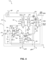
- the Fig. 3 and 4 now show a second and a third embodiment of the electropneumatic parking brake device 1 according to the first embodiment ( Fig. 1 ), which in turn is designed as a parking brake module 2 and wherein the bypass valve 50 is integrated into the parking brake module 2, namely in a common module housing 4.
- the first embodiment Fig. 1
- Identical and similar elements are provided with the same reference numerals, so that reference is made to the above description in its entirety.
- the pilot valve unit 32 differs from the pilot valve unit 32 according to the first embodiment ( Fig. 1 ).
- the other elements are identical, so reference is made to the above description for them.
- a supply pressure path 70 extends from the supply connection 6 and is divided into a supply branch 74, a control branch 76 and a compensation path 86.
- the compensation path 86 pneumatically connects the supply pressure path 70 to a parking brake control pressure line 33, which provides the parking brake control pressure pPS to the main valve unit 34.
- a compensation valve 80 is arranged in the compensation path 82.
- the compensation valve 80 is designed as a 3/2-way valve.
- the compensation valve 80 has a first compensation valve connection 80.1, which is pneumatically connected to the supply pressure path 70.
- the compensation valve 80 has a second compensation valve connection 80.2, which is pneumatically connected to the compensation path 82.
- the compensation valve 80 has a third compensation valve connection 80.3, which is pneumatically connected to a vent line 44.
- the vent line 44 is connected to a vent connection 3, which vents to the environment.
- the compensation valve 80 has a compensation valve control port 80.4, which is pneumatically connected to the second compensation valve port 80.2 via a compensation control path 83. Pneumatic self-locking is preferably implemented by means of the compensation control path 83. A pressure present at the second compensation valve port 80.2, in particular a parking brake control pressure pPS, is provided to the compensation valve control port 80.4 via the compensation control path 83.
- the first compensation valve connection 80.1 is pneumatically connected to the second compensation valve connection 80.2, and preferably the third compensation valve connection 80.3 is blocked.
- the supply pressure path 70 is thus pneumatically connected to the compensation path 82 and thus to the parking brake control pressure line 33.
- the second compensation valve connection 80.2 is pneumatically connected to the third compensation valve connection 80.3, and preferably the first compensation valve connection 80.1 is blocked.
- the compensation path 82 and thus the parking brake control pressure line 33 is pneumatically connected to the vent port 3.
- the compensation valve 80 has a first throttle 27 between the first compensation valve connection 80.1 and the second compensation valve connection 80.2.
- the first throttle 27 advantageously has a nominal diameter that is smaller than the compensation path 82 and/or the supply pressure path 70.
- the compensation valve 80 has a second throttle 28 between the second compensation valve connection 80.2 and the third compensation valve connection 80.3.
- the second throttle 28 advantageously has a nominal diameter that is smaller than the compensation path 82 and/or the vent line 44.
- the pilot valve unit 32 has in the embodiment shown here ( Fig. 3 ) a first pilot valve 41 and a second pilot valve 42, each designed as a 2/2-way solenoid valve.
- first pilot valve 41 in an open position 41A, the supply pressure pV from the supply pressure path 70 can be provided as parking brake control pressure pPS to the parking brake control pressure line 33.
- the parking brake control pressure line 33 is arranged between the first pilot valve 41 and the second pilot valve 42 and is or can be connected pneumatically to the relay valve control connection 16.4 or the shuttle valve 60.
- the parking brake control pressure pPS in the parking brake control pressure line 33 in particular at the relay valve control connection 16.4, can be captured or held for permanent actuation.
- the second pilot valve 42 is also in a blocking position 42B.
- the parking brake control unit 10 provides the first switching signal S1 to actuate the first pilot valve 41 and the second switching signal S2 to actuate the second pilot valve 42.
- the second pilot valve 42 By switching the second pilot valve 42 to an open position 42A, the parking brake control pressure line 33 for venting the relay valve control connection 16.4 can be pneumatically connected to the vent line 44.
- the parking brake control pressure line 33 is additionally—as already known from the first exemplary embodiment—pneumatically connectable to the anti-compound connection 62.
- an additional parking brake pressure pSZ can be provided to the parking brake control pressure line 33 and, in particular, to the relay valve control connection 16.4 in order to control a parking brake pressure pBP at the spring-loaded connection 8, 9 independently of the pilot valve unit 32.
- the additional parking brake pressure pSZ can be provided by a service brake function (not shown here) in order to implement an anti-compound function.
- the electropneumatic parking brake device 1 has a parking brake pressure sensor 64 which is pneumatically connected to the spring-loaded connection 8, 9 for measuring the parking brake pressure pBP.
- the third embodiment according to Fig. 4 is based on the second embodiment according to Fig. 3 .
- the only difference between the third embodiment ( Fig. 4 ) and the second embodiment ( Fig. 2 ) is that the bypass branch line 56 does not branch off from the parking brake pressure line 54, i.e., downstream of the relay valve 16, but rather between the pilot valve unit 32 and the main valve unit 34, so that the bypass valve 50 can vent or supply the parking brake control pressure pPS, depending on the switching position. This can increase air flow efficiency.
- Fig. 5 now shows a second vehicle 200, which is essentially based on the embodiment of the Fig. 1 so that identical and similar elements are provided with the same reference numerals and the differences are highlighted below.
- the vehicle has 200 according to Fig. 5 an electropneumatic parking brake device 1 in which the bypass valve 50 is arranged separately and externally to the parking brake valve unit 24.
- the parking brake valve unit 24 is integrated together with the parking brake control unit 10 into a conventional parking brake module 25.
- the parking brake module 25 has a parking brake module housing 26.
- the bypass valve 50 can be flanged to the parking brake module housing 26 or installed separately and remotely from it in the brake system 204.
- the bypass branch line 56 then branches off externally from the parking brake module 25, specifically from a spring brake pressure line 46a, 46b, which runs from the first spring brake connection 8 to the first and third spring brake cylinders 242a, 242c or from the second spring brake connection 9 to the second and fourth spring brake cylinders 242b, 242d. From which of the first and second spring brake pressure lines 46a, 46b the bypass branch line 56 branches off is functionally irrelevant and should be selected so that the smallest possible installation space is achieved. In the example shown here ( Fig. 5 ), the bypass branch line 56 branches off from the second spring brake pressure line 46b via a bypass branch node 57. Since (as in Fig.
- first and second spring-loaded brake connections 8, 9 are connected internally in the electropneumatic parking brake module 2 directly and without further intermediate circuits, it is sufficient to vent or release one of the first and second spring-loaded brake pressure lines 46a, 46b in order to vent or release all four spring-loaded brake cylinders 242a - 242d.
- Fig. 6 and 7 now show embodiments which are used in the context of the vehicle 200 according to Fig. 5 can be used and thus also include externally arranged bypass valves 50. Identical and similar elements are again provided with the same reference numerals, so that reference is made in full to the above description. In the following, the differences from the previous embodiments are particularly highlighted.
- the Fig. 6 The embodiment shown is largely based on the one in Fig. 1
- the embodiment shown and in particular the pilot valve unit 32 and the main valve unit 34 are of identical design.
- the bypass branch line 56 branches off externally from the parking brake module housing 26 and thus also downstream from the second spring-loaded brake connection 9.
- the bypass supply line 53 also runs externally to the parking brake module housing 26 and branches off from the bypass supply node 51, which is arranged upstream of the supply connection 6, i.e. between the parking brake supply 26 and the supply connection 6.
- the bypass valve 50 is therefore constructed completely parallel to the parking brake valve unit 24 and can connect the second spring-loaded brake pressure line 46b immediately and directly to the parking brake supply 26.
- the Fig. 7 The embodiment shown now differs from the one in Fig. 6 shown embodiment in that the second bypass valve connection 50.2 is not connected to the parking brake supply 26 via a bypass supply line 53, but to a vent 3. In this embodiment, it is therefore not possible to vent the spring-loaded connection 8, but only to vent it.
Landscapes
- Engineering & Computer Science (AREA)
- Transportation (AREA)
- Mechanical Engineering (AREA)
- Braking Systems And Boosters (AREA)
Description
- Die Erfindung betrifft eine elektropneumatische Feststellbremseinrichtung zur Belüftung und Entlüftung von einem oder mehreren Federspeicherzylindern eines elektronisch steuerbaren pneumatischen Bremssystems für ein Fahrzeug, umfassend eine Parkbremsventileinheit mit einem Vorratsanschluss zum Empfangen von Vorratsdruck von einem Parkbrems-Vorrat, wobei die Parkbremsventileinheit in Abhängigkeit von einem Parkbremssignal einen Parkbremsdruck an wenigstens einem Federspeicheranschluss aussteuert, und ein zwischen der Parkbremsventileinheit und dem Parkbrems-Vorrat (26) angeordnetes Rückschlagventil, um ein Rückströmen von Druckluft von der Parkbremsventileinheit zum Parkbrems-Vorrat zu verhindern.
- Die Erfindung betrifft ferner ein elektronisch steuerbares pneumatisches Bremssystem für ein Fahrzeug, umfassend wenigstens einen ersten Vorderachsbremsaktuator und einen zweiten Vorderachsbremsaktuator an einer Vorderachse des Fahrzeugs und wenigstens einen ersten Hinterachsbremsaktuator und einen zweiten Hinterachsbremsaktuator an einer Hinterachse des Fahrzeugs, sowie ein Primärsystem mit einer Primär-Steuereinheit wenigstens zum Ansteuern des ersten Vorderachsbremsaktuators, des zweiten Vorderachsbremsaktuators, des ersten Hinterachsbremsaktuators und des zweiten Hinterachsbremsaktuators.
- Die Erfindung betrifft weiter ferner Verfahren zum Steuern eines elektronisch steuerbaren pneumatischen Bremssystems, mit den Schritten: Ansteuern einer Parkbremsventileinheit mittels einer Parkbrems-Steuereinheit zum Be- und Entlüften von wenigsten einem Federspeicherbremszylinder an einer Hinterachse eines Nutzfahrzeugs, wobei die Parkbremsventileinheit über ein Rückschlagventil mit einem Parkbrems-Vorrat verbunden ist und von diesem Vorratsdruck empfängt; und Ermitteln eines Fehlers in dem elektronisch steuerbaren pneumatischen Bremssystem, insbesondere der Parkbrems-Steuereinheit oder Parkbremsventileinheit.
- Elektropneumatische Ventilanordnungen zum Betätigen einer Feststellbrems-funktion werden sowohl im europäischen als auch im US-amerikanischen Raum eingesetzt. Eine Feststellbremsfunktion eines elektropneumatischen Bremssystems nutzt in der Regel sogenannte Federspeicherbremszylinder, die aufgrund einer Federkraft zuspannen und im belüfteten Zustand geöffnet sind. Während der Fahrt sollen dieser Federspeicherbremszylinder also belüftet und damit geöffnet sein, während sie im geparkten Zustand des Fahrzeugs entlüftet werden und damit zuspannen.
- Eine Lösung, um derartige Federspeicherbremszylinder zu belüften, ist in
DE 10 2017 005 757 A1 offenbart. Die dort offenbarte Lösung nutzt eine Vorsteuerventileinheit sowie eine Hauptventileinheit, wobei die Vorsteuerventileinheit ein elektromagnetisches Magnetventil in Form eines Bistabilventils umfasst. Die Hauptventileinheit ist in der dort offenbarten Lösung durch ein Relaisventil gebildet. Je nach Schaltstellung des elektromagnetischen Bistabilventils wird ein Steuerdruck an der Hauptventileinheit ausgesteuert, die dann in entsprechender Weise einen Volumendruck für die Federspeicherbremszylinder aussteuert. Als Bistabilventil wird ein Magnetventil bezeichnet, welches zwei stabile Schaltstellungen, insbesondere eine stabile Belüftungsstellung und eine stabile Entlüftungsstellung hat. Zu diesem Zweck kann durch Bestromen eines ersten Elektromagneten ein Anker des Magnetventils in eine erste Stellung verbracht werden, sodass das Magnetventil die Belüftungsstellung einnimmt und durch Bestromen eines zweiten Elektromagneten der Anker des Magnetventils in eine zweite Stellung verbracht werden, sodass das Magnetventil die Entlüftungsstellung einnimmt. Wenn dann keine andere Kraft auf den Anker wirkt, oder dieser in den Stellungen mechanisch und/oder magnetisch verrastbar ist, ist die jeweilige Schaltstellung stabil, da sie ohne weitere Bestromung aufrechterhalten bleiben kann. - Eine Bremsanlage mit einer weiteren gattungsgemäßen Parkbremseinrichtung ist in
DE 103 36 611 A1 offenbart. Sie offenbart eine druckmittelbetriebene Bremsanlage für ein Fahrzeug mit einer Feststellbrems-Funktion, bei der infolge manueller Betätigung eines elektrischen Feststellbrems-Signalgebers wenigstens eine Radbremse der Bremsanlage ohne Betätigung eines Bremspedals über einen mit dem Druckmittel beaufschlagbaren Aktuator betätigbar ist. Hiervon ausgehend, wird eine druckmittelbetriebene Bremsanlage für ein Fahrzeug angegeben, bei der eine über einen elektrischen Signalgeber betätigbare Feststegbrems-Funktion unter Einhaltung der einschlägigen Sicherheitsbestimmungen für Bremsanlagen mit geringem Aufwand integrierbar ist. Dies wird dadurch erreicht, dass ein Feststellbrems-Modul vorgesehen ist, in welche eine elektronische Steuereinrichtung sowie eine von der elektronischen Steuereinrichtung elektrisch betätigbare Ventileinrichtung integriert sind, wobei die elektronische Steuereinrichtung bei Empfang eines die Aktivierung der Feststellbrems-Funktion anfordernden elektrischen Betätigungssignals des Feststellbrems-Signalgebers die Feststegbrems-Funktion aktiviert, wobei die elektronische Steuereinrichtung im Rahmen der Feststellbrems-Funktion mittels der elektrisch betätigbaren Ventileinrichtung die Druckmittel-Beaufschlagung des Aktuators steuert. - Ferner offenbart
DE 10 2008 007 877 B3 eine Parkbremseinrichtung für Kraftfahrzeuge mit einem von einem Relaisventil ansteuerbaren FederspeicherBremszylinder, wobei das Relaisventil über ein als 3/2-Wegeventil ausgebildetes Sicherheitsventil ansteuerbar ist, dessen Ausgang wahlweise mit einem von zwei Eingängen verbindbar ist, wobei die Eingänge des Sicherheitsventils über ein erstes oder ein zweites Magnetventil, wahlweise mit einer Druckmittelquelle oder Atmosphärendruck, verbindbar sind, und wobei ein Select-Low-Ventil mit dem einen Eingang und dem Ausgang des Sicherheitsventiles verbunden ist und ein Ausgang des Select-Low-Ventils mit einem Steuereingang des Relaisventils verbunden ist. Hierdurch soll die Stabilität des Systems verbessert werden. - Weiterhin ist aus
DE 10 2015 008 377 A1 ein Feststellbremsmodul bekannt, mit dem eine Druckmittelbeaufschlagung mindestens eines Bremsaktuators steuerbar ist, wobei das Feststellbremsmodul eine elektronische Steuereinrichtung, mindestens ein von der Steuereinrichtung betätigbares Magnetventil, ein druckmittelmengenverstärkendes Ventil zur Druckmittelbeaufschlagung des mindestens einen Bremsaktuators und mindestens einen Druckmitteleingang, über den dem Feststellbremsmodul Druckmittel zuführbar ist, aufweist. Das Feststellbremsmodul weist einen Notlöse-Druckmittelanschluss und ein Doppelrückschlagventil auf, das Feststellbremsmodul weist eine erste Druckmittelleitung auf, mit der der Notlöse-Druckmittelanschluss über ein Rückschlagventil mit dem Versorgungseingang des druckmittelmengenverstärkenden Ventils derart fluidisch verbunden ist, dass Druckmittel durch diese erste Druckmittelleitung von dem Notlöse-Druckmittelanschluss zu dem druckmittelmengenverstärkenden Ventil strömt, falls der an dem Notlöse-Druckmittelanschluss anliegende Druck größer als der an dem Versorgungseingang des druckmittelmengenverstärkenden Ventils anliegende Druck ist, und das Feststellbremsmodul weist eine zweite Druckmittelleitung auf, mit der der Notlöse-Druckmittelanschluss oder ein weiterer Druckmittelanschluss des Feststellbremsmoduls mit einem Eingang des Doppelrückschlagventils derart fluidisch verbunden ist, dass Druckmittel durch diese zweite Druckmittelleitung von dem Notlöse-Druckmittelanschluss zu dem Doppelrückschlagventil strömt, falls der an dem Notlöse-Druckmittelanschluss anliegende Druck größer als der an dem Eingang des Doppelrückschlagventils anliegende Druck ist, oder dass Druckmittel durch diese zweite Druckmittelleitung von dem weiteren Druckmittelanschluss zu dem Doppelrückschlagventil strömt, falls der an dem weiteren Druckmittelanschluss anliegende Druck größer als der an dem Eingang des Doppelrückschlagventils anliegende Druck ist. - Auch wenn die vorstehend beschriebenen Systeme vorteilhaft sind und in der Praxis gut funktionieren, besteht weiterhin Bedarf, die Sicherheit solcher Systeme weiter zu verbessern. Insbesondere soll auch bei "by wire" angesteuerten Systemen ein Noteinlegen der Parkbremse möglich sein für den Fall, dass ein Parkbremssystem oder eine das Parkbremssystem ansteuernde Steuereinheit nicht oder nicht richtig funktioniert.
- Die vorliegende Erfindung löst die Aufgabe bei einer elektropneumatischen Feststellbremseinrichtung der eingangs genannten Art dadurch, dass ein Bypassventil vorgesehen ist, welches zum Belüften und zum Entlüften des Federspeicheranschlusses schaltbar ist, wobei das Bypassventil unabhängig von der Parkbremsventileinheit angesteuert und geschaltet wird.
- Das zusätzliche Bypassventil, das neben der im Allgemeinen bekannten Parkbremsventileinheit vorgesehen ist, dient neben der Parkbremsventileinheit zum Be- und/oder Entlüften des Federspeicheranschlusses und ist unabhängig von der Parkbremsventileinheit ansteuer- und schaltbar. Das Bypassventil bildet so einen Bypass zur Parkbremsventileinheit und kann geschaltet werden, entweder zum Belüften und/oder zum Entlüften des Federspeicheranschlusses für den Fall, dass die Parkbremsventileinheit nicht oder nicht richtig funktioniert oder nicht oder nicht richtig angesteuert werden kann. Insofern beruht die Erfindung auf der Idee, dass das Bypassventil unabhängig von der Parkbremsventileinheit angesteuert und auch unabhängig von dieser geschaltet werden kann.
- Es hat sich gezeigt, dass bei elektropneumatischen Feststellbremseinrichtungen, bei denen ein Rückschlagventil zwischen der Parkbremsventileinheit und dem Parkbrems-Vorrat angeordnet ist, um ein Rückströmen von Druckluft von der Parkbremsventileinheit zum Parkbrems-Vorrat zu verhindern, ein Noteinlegen der an den Federspeicheranschluss angeschlossenen Federspeicherbremszylinder "by wire" nur erschwert oder gar nicht möglich ist. Typische Routinen zum Noteinlegen von Federspeicherbremszylindern derartiger elektropneumatischer Feststellbremseinrichtungen umfassen ein Absenken des Vorratsdrucks des Parkbrems-Vorrats, ein sogenanntes "Herunterpumpen", um auf diese Weise den Druck abzusenken, der üblicherweise den Federspeicherbremszylindern bereitgestellt werden kann. Sinkt der Vorratsdruck ab, aus dem der Arbeitsdruck für die Federspeicherbremszylinder gespeist wird, spannen die Federspeicherbremszylinder selbsttätig zu, da diese durch die Kraft der Federn zugespannt werden. Ist aber ein Rückschlagventil vorgesehen, kann Druckluft nicht von der Parkbremsventileinheit zum Parkbrems-Vorrat zurückströmen und somit auch kein Druckausgleich vom Federspeicherbremszylinder bis zum abgesenkten Druckluftvorrat stattfinden. Das heißt, unabhängig von dem Niveau in dem Druckluftvorrat bleiben die Federspeicherbremszylinder gelöst, da der in diesen herrschende Druck durch das Rückschlagventil eingesperrt wird. Ein Entlüften der Federspeicherbremszylinder und somit Einlegen der Federspeicherbremszylinder ist nur dann möglich, wenn die Parkbremsventileinheit in eine Entlüftungsstellung geschaltet wird. Dies ist aber gerade bei einem Fehler in der Parkbremsventileinheit oder einer diese ansteuernden elektronischen Steuereinheit nicht möglich. Folglich muss in diesen Fällen ein manuelles Einlegen der Federspeicherbremszylinder beispielsweise durch manuelles Entlüften der Federspeicherbremszylinder erfolgen.
- Die Erfindung bietet hier Abhilfe, indem das Bypassventil vorgesehen ist, welches vorzugsweise sowohl zum Be- als auch zum Entlüften des Federspeicheranschlusses schaltbar ist, und zwar unabhängig von der Parkbremsventileinheit. Für den Fall, dass die Parkbremsventileinheit also nicht oder nicht richtig funktioniert oder nicht oder nicht richtig angesteuert werden kann, kann die Bypassventileinheit manuell oder automatisch geschaltet werden, um den Federspeicheranschluss und in der Folge die an diesen angeschlossenen Federspeicherbremszylinder zu entlüften. Auf diese Weise ist ein Noteinlegen der Federspeicherbremszylinder auch dann möglich, wenn die Parkbremsventileinheit nicht oder nicht richtig funktioniert oder nicht oder nicht richtig angesteuert werden kann. Im umgekehrten Fall, wenn ein Belüften und somit Lösen der Federspeicherbremszylinder nicht oder nicht richtig funktioniert, kann das Bypassventil geschaltet werden, um ein Belüften des Federspeicheranschlusses und somit Lösen der an diesen angeschlossenen Federspeicherbremszylinder zu bewirken.
- Das Bypassventil kann ein oder mehrere schaltbare elektromagnetische Ventile umfassen, die insbesondere kostengünstiger ausgelegt werden können als Ventile der Parkbremsventileinheit. Das Bypassventil dient nur im Fehlerfall der Parkbremsventileinheit zum Be- oder Entlüften des Federspeicheranschlusses und kommt somit im Betrieb des Fahrzeugs nur sehr selten zum Einsatz. Es dient lediglich dazu, einen Fail-Operational-Betrieb zu ermöglichen, um so eine Redundanzebene für die Parkbremsventileinheit bereitzustellen.
- In einer bevorzugten Ausführungsform ist das Bypassventil elektromagnetisch ausgebildet und ist von einer von der Parkbremsventileinheit unabhängigen weiteren elektronischen Steuereinheit ansteuerbar. Die Parkbremsventileinheit wird vorzugsweise von einer Parkbrems-Steuereinheit angesteuert, die Teil der elektropneumatischen Feststellbremseinrichtung sein kann. Die Parkbrems-Steuereinheit kann mit der Parkbremsventileinheit zu einem Modul integriert sein. Die Parkbrems-Steuereinheit kann über eine eigene Intelligenz verfügen, oder nur Endstufen umfassen, die über eine elektrische Verbindung mit einer übergeordneten Steuereinheit verbunden sind. Die weitere elektronische Steuereinheit, die das Bypassventil ansteuert, ist verschieden von der Parkbrems-Steuereinheit. Die weitere elektronische Steuereinheit ist vorzugsweise eine bereits in dem elektronisch steuerbaren pneumatischen Bremssystem vorhandene Steuereinheit, oder eine separat für das Bypassventil vorgesehene Steuereinheit. Besonders effizient und platzsparend ist allerdings, wenn eine bereits im elektronisch steuerbaren pneumatischen Bremssystem vorhandene Steuereinheit verwendet wird, um das Bypassventil anzusteuern. Auf diese Weise kann sichergestellt werden, dass für den Fall, dass die Parkbrems-Steuereinheit einen Fehler hat, das Bypassventil immer noch durch die weitere Steuereinheit angesteuert und geschaltet werden kann, um den Federspeicheranschluss zu be- oder zu entlüften.
- Vorzugsweise weist die elektropneumatische Feststellbremseinrichtung einen Bypassdrucksensor auf, zum Erfassen des am Federspeicheranschluss ausgesteuerten Parkbremsdrucks, wobei der Bypassdrucksensor mit der von der Parkbremsventileinheit unabhängigen weiteren elektronischen Steuereinheit verbunden ist. Auf diese Weise kann die weitere elektronische Steuereinheit den am Federspeicheranschluss anliegenden Druck auswerten und in Abhängigkeit davon das Bypassventil ansteuern. Eine Regelung des Parkbremsdrucks kann auf diese Weise realisiert werden.
- Weiterhin ist bevorzugt, dass das Bypassventil monostabil ist und eine Sperrstellung sowie eine Durchlassstellung einnehmen kann, wobei das Bypassventil stabil in der Sperrstellung ist. Das Bypassventil kann in diesem Fall beispielsweise als 2/2-Wege-Ventil ausgebildet sein und federbelastet in die Sperrstellung geschaltet werden. Erst durch Bestromen wird das Bypassventil dann in die Durchlassstellung geschaltet, in der der Federspeicheranschluss belüftet bzw. entlüftet werden kann. Um dies bei einem 2/2-Wege-Ventil zu realisieren, ist das als Bypassventil ausgebildete 2/2-Wege-Ventil vorzugsweise mit einem ersten Bypassventilanschluss mit dem Federspeicheranschluss verbunden und mit einem zweiten Bypassventilanschluss mit dem Parkbrems-Vorrat verbunden, bzw. einer Vorratsdruckleitung, die zwischen dem Parkbrems-Vorrat und dem Rückschlagventil verläuft, sodass das Bypassventil das Rückschlagventil umgeht. Für den Fall, dass der Parkbrems-Vorrat nun Druckluft führt und einen ausreichend hohen Druck bereitstellen kann, kann durch Schalten des Bypassventils in die Durchlassstellung unter Umgehung des Rückschlagventils und der Parkbremsventileinheit der Federspeicheranschluss belüftet werden. Für den Fall, dass aufgrund eines Fehlers oder einer Fehlerlöseroutine der Parkbrems-Vorrat weitgehend oder vollständig drucklos ist (beispielsweise durch Herunterpumpen), kann durch Schalten des Bypassventils in die Durchlassstellung unter Umgehung der Parkbremsventileinheit und des Rückschlagventils der Federspeicheranschluss mit dem dann drucklosen Parkbrems-Vorrat verbunden werden, sodass der Federspeicheranschluss in diesem Fall entlüftet werden kann.
- Gemäß einer weiteren bevorzugten Ausführungsform ist vorgesehen, dass das Bypassventil einen mit dem Federspeicheranschluss oder einer dem Federspeicheranschluss vorgeschalteten Hauptventileinheit verbundenen ersten Bypassventilanschluss und einen mit einer Entlüftung verbundenen zweiten Bypassventilanschluss aufweist. Alternativ hierzu weist das Bypassventil einen mit dem Federspeicheranschluss oder einer dem Federspeicheranschluss vorgeschalteten Hauptventileinheit verbundenen ersten Bypassventilanschluss und einen mit dem Parkbrems-Vorrat stromaufwärts des Rückschlagventils verbundenen zweiten Bypassventilanschluss auf. Der zweite Bypassventilanschluss kann demnach entweder mit einer Entlüftung oder dem Parkbrems-Vorrat verbunden sein. Dies ist insbesondere dann bevorzugt, wenn das Bypassventil wie vorstehend beschrieben als 2/2-Wege-Ventil ausgebildet ist. Ist der zweite Bypassventilanschluss lediglich mit der Entlüftung verbunden, kann der Federspeicheranschluss durch das Bypassventil in der Durchlassstellung nur entlüftet werden. Ist der zweite Bypassventilanschluss hingegen mit dem Parkbrems-Vorrat verbunden, kann der Federspeicheranschluss belüftet werden, wenn der Parkbrems-Vorrat ausreichend Druck führt, und entlüftet werden, wenn der Parkbrems-Vorrat heruntergepumpt ist.
- Gemäß einer bevorzugten Weiterbildung ist vorgesehen, dass das Bypassventil mit der Parkbremsventileinheit als eine Baueinheit ausgebildet ist. Das Bypass-ventil kann dazu mit der Parkbremsventileinheit in einem Modulgehäuse untergebracht sein oder lediglich an die Parkbremsventileinheit angeflanscht bzw. mit dieser formatiert sein. Dies ist besonders vorteilhaft, da auf diese Weise der Montageaufwand reduziert werden kann und Bauteile kompakt ausgebildet werden können. Außerdem können auf diese Weise Schnittstellen zwischen einzelnen Elementen verringert werden und Leitungen entfallen, die sonst anfällig für Leckage sein können.
- Vorzugsweise ist das Bypassventil unmittelbar mit einer stromabwärts des Federspeicheranschlusses an diesen angeschlossenen Parkbremsdruckleitung verbunden. Diese Gestaltung ist insbesondere dann vorteilhaft, wenn das Bypassventil extern zu der Parkbremsventileinheit ist, beispielsweise an diese angeflanscht oder außerhalb eines Modulgehäuses an dieser angeordnet, oder als separates Bauteil dargestellt ist. Die unmittelbare Verbindung des Bypassventils mit einer stromabwärts des Federspeicheranschlusses an diesen angeschlossenen Parkbremsdruckleitung, die ihrerseits wiederum zum Federspeicherbremszylinder führt, kann zu einer unmittelbaren Entlüftung bzw. Belüftung des Federspeicherbremszylinders führen. Es ist auch denkbar, dass das Bypassventil unmittelbar an den Federspeicherbremszylinder angeschlossen ist.
- In einer bevorzugten Weiterbildung weist die Parkbremsventileinheit eine Vorsteuerventileinheit und eine Hauptventileinheit auf. Eine solche Gestaltung ist im Grunde im Stand der Technik bekannt. In einer solchen Ausbildung ist die Vorsteuerventileinheit dazu vorgesehen, einen Parkbremssteuerdruck an der Hauptventileinheit bereitzustellen, die dann in Abhängigkeit von dem empfangenen Parkbremssteuerdruck den Parkbremsdruck an dem Federspeicheranschluss aussteuert. Die Hauptventileinheit ist hierzu in der Regel volumenverstärkend gebildet und kann beispielsweise ein Relaisventil oder ein pneumatisch schaltbares Hauptventil umfassen. Derartige Gestaltungen lassen eine effizientere Luftnutzung zu, da bei Variation des Parkbremsdrucks nur der im Volumen geringere Parkbremssteuerdruck entlüftet werden muss, sodass ein Luftmengenverbrauch insgesamt reduziert sein kann.
- Bevorzugt ist das Bypassventil mit der Hauptventileinheit verbunden, wobei der Parkbremssteuerdruck über das Bypassventil entlüftbar ist. Das Bypassventil ist auf diese Weise vorzugsweise über dieselbe Leitung mit der Hauptventileinheit verbunden, über die auch die Vorsteuerventileinheit mit der Hauptventileinheit verbunden ist. Die Hauptventileinheit ist vorzugsweise rein pneumatisch ausgebildet und kann daher unabhängig von einer Parkbremssteuereinheit und unabhängig von einer Stromquelle schalten. Für den Fall, dass die Vorsteuerventileinheit nicht oder nicht richtig funktioniert, kann auf diese Weise über das Bypassventil der Parkbremssteuerdruck entlüftet werden, sodass in der Folge auch der Federspeicheranschluss entlüftet wird.
- In einer bevorzugten Weiterbildung ist das Bypassventil dazu mit einer Bypassabzweigleitung verbunden, die von einer Parkbremssteuerdruckleitung abzweigt, über die von der Vorsteuerventileinheit der Parkbremssteuerdruck an der Hauptventileinheit bereitgestellt wird. In einer weiteren bevorzugten Ausgestaltung ist in der Parkbremssteuerdruckleitung ein erstes Wechselventil vorgesehen, welches einen mit der Vorsteuerventileinheit verbundenen ersten Wechselventilanschluss, einen mit einem Anti-Compound-Anschluss verbundenen zweiten Wechselventilanschluss und einen mit der Hauptventileinheit verbundenen dritten Wechselventilanschluss aufweist. Das erste Wechselventil ist vorzugsweise so ausgebildet, dass jeweils der an dem ersten Wechselventilanschluss und dem zweiten Wechselventilanschluss höhere anstehende Druck an dem dritten Wechselventilanschluss ausgesteuert wird. Diese Gestaltung erlaubt es, entweder den von der Vorsteuerventileinheit ausgesteuerten Parkbremssteuerdruck oder einen über den Anti-Compound-Anschluss bereitgestellten Druck an der Hauptventileinheit auszusteuern.
- Ein Anti-Compound-Anschluss wird insbesondere dazu verwendet, eine Überlastung von Bremsaktuatoren zu vermeiden. An den Federspeicheranschluss werden bei den meisten Bremssystemen sogenannte Tristop-Zylinder angeschlossen, die sowohl als Betriebsbremszylinder als auch als Parkbremszylinder wirken können. Wird nun der Federspeicherteil des Tristop-Zylinders entlüftet, um die Feststellbremsfunktion zu aktivieren, kann es vorkommen, dass auch der Betriebsbremsteil des Tristop-Zylinders aktiviert wird, wenn beispielsweise ein Bediener des Fahrzeugs ein Bremspedal betätigt. In diesem Fall würden sowohl der Federspeicherteil als auch der Betriebsbremsteil eine Kraft ausüben, was zu einer Überlastung von Bauteilen führen kann. Bei einer sogenannten Anti-Compound-Funktion wird der an dem Tristop-Zylinder ausgesteuerte Betriebsbremsdruck gleichzeitig über den Anti-Compound-Anschluss der Feststellbremseinrichtung zugeführt, die in der Folge einen Parkbremsdruck an dem Federspeicheranschluss aussteuert, um in gleicher Weise den Federspeicherteil des Tristop-Zylinders zu belüften und somit zu lösen. Das heißt, in der gleichen Weise, in der der Betriebsbremsteil eine Kraft ausübt, wird eine Kraft, die durch den Federspeicherteil ausgeübt wird, reduziert.
- Bevorzugt ist ferner, dass die Bypass-Abzweigleitung zwischen dem ersten Wechselventilanschluss und der Vorsteuerventileinheit abzweigt. Das Bypass-ventil soll so ausgebildet sein, dass es den Parkbremssteuerdruck entlüften kann, und nicht den Anti-Compound-Druck, der an dem Anti-Compound-Anschluss bereitgestellt wird. Die Anti-Compound-Funktion bleibt also unabhängig von der Schaltung des Bypassventils bestehen.
- In einer bevorzugten Ausführungsform ist ferner vorgesehen, dass die Parkbremsventileinheit ein Kompensationsventil aufweist, welches dazu vorgesehen ist, einen von der Vorsteuerventileinheit an der Hauptventileinheit ausgesteuerten Parkbremssteuerdruck aufrechtzuerhalten und so eine Leckage der Vorsteuerventileinheit und/oder der Hauptventileinheit wenigstens teilweise auszugleichen. Durch das Kompensationsventil können vorteilhaft Leckagen kompensiert werden, die in der Vorsteuerventileinheit und/oder der Hauptventileinheit auftreten. Dies wird vorteilhaft durch eine steuerbare pneumatische Verbindung zu dem Parkbrems-Vorrat oder zu einem Entlüftungsanschluss ermöglicht, die durch das Kompensationsventil herstellbar ist.
- Das Kompensationsventil ist vorzugsweise als pneumatisch schaltbares 3/2-Wege-Ventil ausgebildet und weist einen mit dem Rückschlagventil verbundenen ersten Kompensationsventilanschluss, einen mit einer den Parkbremssteuerdruck führenden Leitung verbundenen zweiten Kompensationsventilanschluss und einen mit einer Entlüftung verbundenen dritten Kompensationsventilanschluss auf. Vorzugsweise ist das Kompensationsventil federbelastet in eine erste Schaltstellung vorgespannt, in der der zweite Kompensationsventilanschluss mit dem dritten Kompensationsventilanschluss verbunden ist und falls ein an einem Kompensationsventil-Steueranschluss bereitgestellte Kompensationsventil-Steuerdruck einen Kompensationsventil-Schwellwert überschreitet, in eine zweite Schaltstellung schaltet, in welcher der erste Kompensationsventilanschluss mit dem zweiten Kompensationsventilanschluss verbunden ist. Weiter ist bevorzugt, dass der Kompensationsventil-Steuerdruck ein am zweiten Kompensationsventilanschluss anliegender oder ausgesteuerter Druck ist, wodurch eine pneumatische Selbsthaltung für das Kompensationsventil realisiert wird. Vorzugsweise weist das Kompensationsventil eine Rückstellfeder auf, die das Kompensationsventil in die erste Schaltstellung vorspannt. Vorteilhaft ist das Kompensationsventil, insbesondere durch Auslegung einer oder der Rückstellfeder, ausgebildet, in die zweite Schaltstellung zu schalten, wenn der Kompensationsventil-Schwellwert überschritten wird. Vorteilhaft liegt der Kompensationsventil-Schwellwert in einem Bereich von 0,241 MPa (35 psi) und 0,379 MPa (55 psi), bevorzugt von 0,276 MPa (40 psi) bis 0,345 MPa (50 psi), und beträgt vorzugsweise 0,310 MPA (45 psi).
- Vorteilhaft ist vorgesehen, dass der zweite Kompensationsventilanschluss über einen Kompensationssteuerpfad pneumatisch mit dem Kompensationsventil-Steueranschluss verbunden ist.
- In einer vorteilhaften Weiterbildung ist vorgesehen, dass das Kompensationsventil gedrosselt ausgebildet ist, bevorzugt derart, dass die Verbindung des ersten Kompensationsventilanschlusses mit dem zweiten Kompensationsventilanschluss und/oder die Verbindung des zweiten Kompensationsventilanschlusses mit dem dritten Kompensationsventilanschluss jeweils gedrosselt ist. Insbesondere weist das Kompensationsventil eine erste Drossel zum Drosseln der pneumatischen Verbindung zwischen dem ersten Kompensationsventilanschluss und dem zweiten Kompensationsventilanschluss in der zweiten Schaltstellung auf. Insbesondere weist das zweite Kompensationsventil eine zweite Drossel zum Drosseln der pneumatischen Verbindung zwischen dem zweiten Kompensationsventilanschluss und dem dritten Kompensationsventilanschluss in der ersten Schaltstellung auf. In anderen Weiterbildungen kann eine gemeinsame Drossel vorgesehen werden, die unabhängig von der Schaltstellung des Kompensationsventils ist und dem Kompensationsventil vor- oder nachgeschaltet ist. Vorteilhaft kann eine derartige gemeinsame Drossel zwischen dem zweiten Kompensationsventilanschluss und einem Abzweigknoten für den Kompensationssteuerpfad angeordnet sein. In einer besonders bevorzugten Ausgestaltung ist vorgesehen, dass die Parkbremsventileinheit und das Bypassventil von zwei unabhängigen Spannungsquellen mit elektrischer Spannung versorgt werden. Vorzugsweise wird auch die weitere elektronische Steuereinheit von der Spannungsquelle versorgt, die auch das Bypassventil versorgt. Auf diese Weise kann die Sicherheit erhöht werden und in einem Bremssystem, welches zwei unabhängige Spannungsquellen aufweist, ein Fail-Operational-Betrieb ermöglicht werden.
- In einem zweiten Aspekt löst die Erfindung die eingangs genannte Aufgabe bei einem elektronisch steuerbaren pneumatischen Bremssystem dadurch, dass dieses eine elektropneumatische Feststellbremseinrichtung nach einer der vorstehend beschriebenen bevorzugten Ausführungsformen einer elektropneumatischen Feststellbremseinrichtung gemäß dem ersten Aspekt der Erfindung aufweist, wobei an den wenigstens einen Federspeicheranschluss wenigstens ein erster Federspeicherzylinder an der Hinterachse angeschlossen ist und wobei das Bypassventil zum Belüften und zum Entlüften des ersten Federspeicherzylinders schaltbar ist, wobei das Bypassventil unabhängig von der Parkbremsventileinheit angesteuert und geschaltet wird.
- Es soll verstanden werden, dass die elektropneumatische Feststellbremseinrichtung gemäß dem ersten Aspekt der Erfindung und das elektronisch steuerbare pneumatische Bremssystem gemäß dem zweiten Aspekt der Erfindung gleiche und ähnliche Unteraspekte aufweisen, wie sie insbesondere in den abhängigen Ansprüchen niedergelegt sind. Insofern wird vollumfänglich auf die obige Beschreibung Bezug genommen und bevorzugte Ausführungsformen, Merkmale und Vorteile sollen auch im zweiten Aspekt der Erfindung berücksichtigt und durch Bezug einbezogen werden.
- In einer bevorzugten Ausführungsform des elektronisch steuerbaren pneumatischen Bremssystems ist vorgesehen, dass die Parkbremsventileinheit mit einer Parkbrems-Steuereinheit verbunden ist und von dieser Schaltsignale empfängt, wobei das Bypassventil mit einer von der Parkbremsventileinheit unabhängigen weiteren Steuereinheit verbunden ist und von dieser wenigstens ein Bypass-Schaltsignal empfängt. Bevorzugt ist die Parkbrems-Steuereinheit mit einer ersten Spannungsquelle verbunden und wird von dieser mit elektrischer Spannung versorgt, und die weitere elektronische Steuereinheit ist mit einer zweiten Spannungsquelle verbunden und wird von dieser mit elektrischer Spannung versorgt. Die weitere elektronische Steuereinheit ist vorzugsweise eine in dem elektronisch steuerbaren pneumatischen Bremssystem vorhandene Steuereinheit, wie beispielsweise die Primär-Steuereinheit. Die Primär-Steuereinheit ist typischerweise unabhängig von der Parkbrems-Steuereinheit. Die Parkbrems-Steuereinheit bildet in manchen Konzepten eine Rückfallebene und insofern auch eine Sekundär-Steuereinheit für die erste Redundanzebene des elektronisch steuerbaren pneumatischen Bremssystems. Für den Fall, dass diese Redundanzebene ausfällt, beispielsweise dadurch, dass die Parkbrems-Steuereinheit ausfällt, kann die Primär-Steuereinheit das Bypassventil ansteuern und so eine Entlüftung der Federspeicherbremszylinder oder auch eine Belüftung der Federspeicherbremszylinder herbeiführen. Für den Fall, dass die Parkbremsventileinheit der Primär-Steuereinheit zugeordnet ist, wird das Bypassventil vorzugsweise von einer anderen Steuereinheit wie beispielsweise einer anderen Sekundär-Steuereinheit, die unabhängig von der Primär-Steuereinheit bereitgestellt ist, angesteuert.
- In einer bevorzugten Weiterbildung des elektronisch steuerbaren pneumatischen Bremssystems weist dieses ferner ein Sekundärsystem mit einer Sekundär-Steuereinheit, wenigstens zum Ansteuern des ersten Vorderachsbremsaktuators, des zweiten Vorderachsbremsaktuators, des ersten Hinterachsbremsaktuators und des zweiten Hinterachsbremsaktuators auf, wobei für den Fall, dass im Primärsystem ein Fehler ermittelt wird, die Steuerung des elektronisch steuerbaren pneumatischen Bremssystems wenigstens teilweise durch das Sekundärsystem erfolgt. Das Sekundärsystem bildet in diesem Fall eine erste Rückfallebene. Es kann vorgesehen sein, dass das Sekundärsystem das Primärsystem vollständig ersetzen kann und insofern auch die Sekundär-Steuereinheit die Funktionalität der Primär-Steuereinheit vollständig ersetzen kann. Es kann auch vorgesehen sein, dass die Sekundär-Steuereinheit nur einen begrenzten Funktionsumfang der Primär-Steuereinheit aufweist und insofern keine vollständige Funktionalität, jedoch eine ausreichende Funktionalität, um insbesondere ein "Limp-Home-Manöver" durchzuführen, vorgesehen ist.
- In dieser Variante kann auch vorgesehen sein, dass die Sekundär-Steuereinheit die weitere Steuereinheit, die das Bypassventil ansteuert, bildet oder aufweist. In diesem Fall kann das Bypassventil dann durch die Sekundär-Steuereinheit angesteuert werden, für den Fall, dass die Primär-Steuereinheit nicht oder nicht richtig funktioniert und auch die Parkbrems-Steuereinheit nicht oder nicht richtig funktioniert.
- Auch andere Steuereinheiten, wie beispielsweise eine Steuereinheit eines elektronischen Lenksystems, eine Steuereinheit eines Anhängersteuermoduls, eine Steuereinheit einer Luftfederung oder weitere Steuereinheiten können bevorzugt im Rahmen der Erfindung als weitere Steuereinheiten zum Ansteuern des Bypassventils vorgesehen sein. Hierzu ist es dann jeweils bevorzugt, dass die jeweilige Steuereinheit an ein BUS-System angeschlossen ist, oder so mit einer übergeordneten Steuereinheit kommuniziert, dass die weitere Steuereinheit in der Lage ist, Schaltsignale für das Bypassventil auszusteuern.
- In einem dritten Aspekt wird die eingangs genannte Aufgabe gelöst durch ein Fahrzeug, insbesondere Nutzfahrzeug, mit einer Vorderachse, wenigstens einer ersten Hinterachse und einem elektronisch steuerbaren pneumatischen Bremssystem nach einer vorstehend beschriebenen bevorzugten Ausführungsform des elektronisch steuerbaren pneumatischen Bremssystems gemäß dem zweiten Aspekt der Erfindung. Es soll verstanden werden, dass das Fahrzeug gemäß dem dritten Aspekt der Erfindung, das elektronisch steuerbare pneumatische Bremssystem gemäß dem zweiten Aspekt der Erfindung und die elektropneumatische Feststellbremseinrichtung gemäß dem ersten Aspekt der Erfindung gleiche und/oder ähnliche Unteraspekte aufweisen, wie sie insbesondere in den abhängigen Ansprüchen niedergelegt sind. Insofern wird für Weiterbildungen des Fahrzeugs gemäß dem dritten Aspekt der Erfindung vollumfänglich auf das elektronisch steuerbare pneumatische Bremssystem gemäß dem zweiten Aspekt der Erfindung sowie die elektropneumatische Feststellbremseinrichtung gemäß dem ersten Aspekt der Erfindung verwiesen.
- In einem vierten Aspekt der Erfindung wird die eingangs genannte Aufgabe auch gelöst durch ein Verfahren zum Steuern eines elektronisch steuerbaren pneumatischen Bremssystems, vorzugsweise ein elektronisch steuerbares pneumatisches Bremssystem gemäß einer der vorstehend beschriebenen bevorzugten Ausführungsformen gemäß dem zweiten Aspekt der Erfindung. Das Verfahren weist vorzugsweise die Schritte auf: Ansteuern einer Parkbremsventileinheit mittels einer Parkbrems-Steuereinheit zum Be- und Entlüften von wenigstens einem Federspeicherbremszylinder an einer Hinterachse eines Nutzfahrzeugs, wobei die Parkbremsventileinheit über ein Rückschlagventil mit einem Parkbrems-Vorrat verbunden ist und von diesem Vorratsdruck empfängt; Ermitteln eines Fehlers in dem elektronisch steuerbaren pneumatischen Bremssystem, insbesondere der Parkbrems-Steuereinheit oder/oder der Parkbremsventileinheit; Schalten eines Bypassventils, welches sowohl mit dem wenigstens einen Federspeicherbremszylinder als auch dem Parkbrems-Vorrat verbunden ist, in eine Entlüftungsstellung zum Entlüften des wenigstens einen Federspeicherbremszylinders; wobei das Bypassventil in Antwort auf ein Bypass-Schaltsignal schaltet, welches von einer weiteren elektronischen Steuereinheit bereitgestellt wird, die unabhängig von der Parkbrems-Steuereinheit ist.
- Es soll verstanden werden, dass die elektropneumatische Feststellbremseinrichtung gemäß dem ersten Aspekt der Erfindung, das elektronisch steuerbare pneumatische Bremssystem gemäß dem zweiten Aspekt der Erfindung, das Fahrzeug gemäß dem dritten Aspekt der Erfindung und das Verfahren zum Steuern eines elektronisch steuerbaren pneumatischen Bremssystems gemäß dem vierten Aspekt der Erfindung gleiche und ähnliche Unteraspekte aufweisen, wie sie insbesondere in den abhängigen Ansprüchen niedergelegt sind. Insofern wird für Weiterentwicklungen des Verfahrens zum Steuern eines elektronisch steuerbaren pneumatischen Bremssystems auf die weiteren Ausführungsformen, Vorteile und Merkmale der ersten drei Aspekte der Erfindung vollumfänglich verwiesen.
- In einer bevorzugten Weiterbildung des Verfahrens ist vorgesehen, dass die Parkbrems-Steuereinheit mit einer ersten Spannungsquelle verbunden ist und von dieser mit elektrischer Spannung versorgt wird und die weitere Steuereinheit mit einer zweiten Spannungsquelle verbunden ist und von dieser mit elektrischer Spannung versorgt wird.
- Vorzugsweise umfasst das Verfahren ferner den Schritt: Absenken des Vorratsdrucks im Parkbrems-Vorrat zum Entlüften des wenigstens einen Federspeicherbremszylinders.
- Ausführungsformen der Erfindung werden nun nachfolgend anhand der Zeichnungen beschrieben. Diese sollen die Ausführungsformen nicht notwendigerweise maßstäblich darstellen, vielmehr sind die Zeichnungen, wenn dies zur Erläuterung dienlich ist, in schematisierter und/oder leicht verzerrter Form ausgeführt. Im Hinblick auf Ergänzungen der aus den Zeichnungen unmittelbar erkennbaren Lehren wird auf den einschlägigen Stand der Technik verwiesen. Dabei ist zu berücksichtigen, dass vielfältige Modifikationen und Änderungen betreffend die Form und das Detail einer Ausführungsform vorgenommen werden können, ohne von der allgemeinen Idee der Erfindung abzuweichen. Die in der Beschreibung, in den Zeichnungen sowie in den Ansprüchen offenbarten Merkmale der Erfindung können sowohl einzeln als auch in beliebiger Kombination für die Weiterbildung der Erfindung wesentlich sein. Zudem fallen in den Rahmen der Erfindung alle Kombinationen aus zumindest zwei der in der Beschreibung, den Zeichnungen und/oder den Ansprüchen offenbarten Merkmale. Die allgemeine Idee der Erfindung ist nicht beschränkt auf die exakte Form oder das Detail der im Folgenden gezeigten und beschriebenen bevorzugten Ausführungsformen oder beschränkt auf einen Gegenstand, der eingeschränkt wäre im Vergleich zu dem in den Ansprüchen beanspruchten Gegenstand. Bei angegebenen Bemessungsbereichen sollen auch innerhalb der genannten Grenzen liegende Werte als Grenzwerte offenbart und beliebig einsetzbar und beanspruchbar sein. Der Einfachheit halber sind nachfolgend für identische oder ähnliche Teile oder Teile mit identischer oder ähnlicher Funktion gleiche Bezugszeichen verwendet.
- Weitere Vorteile, Merkmale und Einzelheiten der Erfindung ergeben sich aus der nachfolgenden Beschreibung der bevorzugten Ausführungsformen sowie anhand der Zeichnungen; diese zeigen in:
- Fig. 1
- ein erstes Ausführungsbeispiel einer elektropneumatischen Feststellbremseinrichtung;
- Fig. 2
- ein Nutzfahrzeug mit einem elektronisch steuerbaren pneumatischen Bremssystem sowie einer elektropneumatischen Feststellbremseinrichtung;
- Fig. 3
- ein zweites Ausführungsbeispiel einer elektropneumatischen Feststellbremseinrichtung;
- Fig. 4
- ein drittes Ausführungsbeispiel einer elektropneumatischen Feststellbremseinrichtung;
- Fig. 5
- ein zweites Ausführungsbeispiel eines Nutzfahrzeugs mit einem elektronisch steuerbaren pneumatischen Bremssystem sowie einer elektropneumatischen Feststellbremseinrichtung;
- Fig. 6
- ein viertes Ausführungsbeispiel einer elektropneumatischen Feststellbremseinrichtung; und in
- Fig. 7
- ein fünftes Ausführungsbeispiel einer elektropneumatischen Feststellbremseinrichtung.
- Eine elektropneumatische Feststellbremseinrichtung 1 kann in einer ersten Ausführungsform (
Fig. 1 ) als Feststellbremsmodul 2 ausgebildet sein. Dazu weist es ein Modulgehäuse 4 auf, an welchem ein Vorratsanschluss 6, ein Entlüftungsanschluss 3 sowie ein erster Federspeicheranschluss 8 und ein zweiter Federspeicheranschluss 9 angeordnet sind. Die elektropneumatische Feststellbremseinrichtung 1 umfasst daneben eine Parkbrems-Steuereinheit 10 sowie eine Parkbremsventileinheit 24, die von der Parkbrems-Steuereinheit 10 angesteuert wird. Die Parkbremsventileinheit 24 ist im Grunde wie im Stand der Technik bekannt gebildet und sowohl mit dem Vorratsanschluss 6 verbunden als auch den ersten und zweiten Federspeicheranschlüssen 8, 9. Die Parkbremsventileinheit 24 empfängt von dem Vorratsanschluss 6 Vorratsdruck pV und steuert abhängig vom ersten und zweiten Schaltsignal S1, S2, die von der Parkbrems-Steuereinheit 10 bereitgestellt werden, einen Parkbremsdruck pBP an dem ersten und zweiten Federspeicheranschluss 8, 9 aus. Die ersten und zweiten Schaltsignale S1, S2 werden von der Parkbrems-Steuereinheit 10 basierend auf dem Empfang eines Parkbremssignals SP bereitgestellt. Das Parkbremssignal SP wird von einer übergeordneten Einheit, wie nachfolgend mit Bezug aufFig. 2 näher beschrieben werden wird, bereitgestellt. Es kann auch vorgesehen sein, dass das Parkbremssignal SP unmittelbar an der Parkbremsventileinheit 24 bereitgestellt wird und insofern die elektropneumatische Feststellbremseinrichtung 1 keine eigene Parkbrems-Steuereinheit 10 aufweist, sondern direkt verkabelt ist. - Konkret weist die Parkbremsventileinheit 24 in dem hier gezeigten Ausführungsbeispiel eine Vorsteuerventileinheit 32 und eine Hauptventileinheit 34 auf, wie im Grunde bekannt. Die Vorsteuerventileinheit 32 umfasst in dem hier gezeigten Ausführungsbeispiel ein Bistabilventil 12, mit einem ersten Bistabilventilanschluss 12.1, der mit dem Vorratsanschluss 6 verbunden ist, einem zweiten Bistabilventilanschluss 12.2 und einem dritten Bistabilventilanschluss 12,3, der mit dem Entlüftungsanschluss 3 verbunden ist. Genauer gesagt ist der erste Bistabilventilanschluss 12.1 zunächst mit einem Rückschlagventil 30 verbunden, welches hier in das Modulgehäuse 4 integriert ist und der Parkbremsventileinheit 24 vorgeschaltet ist. Das Rückschlagventil 30 dient dazu, dass Druck nicht von der Parkbremsventileinheit 24 in Richtung des Vorratsanschlusses 6 strömen kann. Vorratsdruck pV wird also nur von dem Vorratsdruck 6 über das Rückschlagventil 30 dem ersten Bistabilventilanschluss 12.1 bereitgestellt, aber ein Druckausgleich kann nicht umgekehrt stattfinden.
- Der zweite Bistabilventilanschluss 12.2 ist hier mit einem Halteventil 14 verbunden, welches als 2/2-Wege-Ventil ausgebildet ist. Das Halteventil 14 weist einen ersten Halteventilanschluss 14.1 sowie einen zweiten Halteventilanschluss 14.2 auf. Das Halteventil 14 ist als 2/2-Wege-Ventil ausgebildet und monostabil. Es ist in einer Öffnungsstellung vorgespannt und kann durch Bereitstellen des zweiten Schaltsignals S2 in eine Sperrstellung (in
Fig. 1 nicht gezeigt) gebracht werden. Der erste Halteventilanschluss 14.1 ist mit dem Bistabilventil 12 verbunden, genauer gesagt mit dem zweiten Bistabilventilanschluss 12.2. Der zweite Halteventilanschluss 14.2 ist mit der Hauptventileinheit 34 verbunden. Das Bistabilventil 12 und das Halteventil 14 bilden zusammen die Vorsteuerventileinheit 32. Es soll verstanden werden, dass das Halteventil 14 auch entfallen kann. Die Vorsteuerventileinheit 32 steuert bei entsprechender Schaltung des Bistabilventils 12 und des Halteventils 14 einen Parkbremssteuerdruck pPS an der Hauptventileinheit 34 aus. Die Hauptventileinheit 34 umfasst in dem hier gezeigten Ausführungsbeispiel ein Relaisventil 16, das einen mit dem Vorratsanschluss 6 verbundenen Relaisventil-Vorratsanschluss 16.1, einen mit dem ersten und zweiten Federspeicheranschluss 8, 9 verbundenen Relaisventil-Arbeitsanschluss 16.2, einen mit dem Entlüftungsanschluss 3 verbundenen Relaisventil-Entlüftungsanschluss 16.3 sowie einen mit der Vorsteuerventileinheit 32 verbundenen Relaisventil-Steueranschluss 16.4 aufweist. Die Vorsteuerventileinheit 32 stellt den Parkbremssteuerdruck pPS an dem Relaisventil-Steueranschluss 16.4 bereit, wobei das Relaisventil 16 dann den Parkbremssteuerdruck pPS volumenverstärkt und als Parkbremsdruck pBP an dem Relaisventil-Arbeitsanschluss 16.2 aussteuert. Zu diesem Zweck empfängt das Relaisventil 16 den Vorratsdruck pV von dem Vorratsanschluss 6. Es soll verstanden werden, dass statt des Relaisventils 16 auch andere volumenverstärkende Ventile, wie beispielsweise ein pneumatisches Schaltventil, eingesetzt werden können. - In dem konkret in
Fig. 1 gezeigten Ausführungsbeispiel ist zwischen dem Halteventil 14 und dem Relaisventil 16 noch ein Wechselventil 60 vorgesehen. Das Wechselventil 60 weist einen ersten Wechselventilanschluss 60.1 auf, der hier konkret mit der Vorsteuerventileinheit 32, nämlich insbesondere dem zweiten Halteventilanschluss 14.2, verbunden ist. Das Wechselventil 60 weist einen zweiten Wechselventilanschluss 60.2 auf, der hier mit einem Anti-Compound-Anschluss 62 verbunden ist, sowie einen dritten Wechselventilanschluss 60.3, der mit dem Relaisventil-Steueranschluss 16.4 verbunden ist. Das Wechselventil 60 ist so ausgebildet, dass der jeweils höhere des am ersten Wechselventilanschluss 60.1 und zweiten Wechselventilanschluss 60.2 anliegende Druck am dritten Wechselventilanschluss 60.3 ausgesteuert wird. Sowohl das Wechselventil 60 als auch der Anti-Compound-Anschluss 62 sind optional und können gemeinsam entfallen. - Durch entsprechendes Bereitstellen des Parkbremssignals SP kann also der Parkbremsdruck pBP an den ersten und zweiten Federspeicheranschlüssen 8, 9 ausgesteuert oder diese entlüftet werden. In der Folge können die Federspeicherbremszylinder, die an den ersten bzw. zweiten Federspeicheranschluss 8, 9 angeschlossen sind, gelöst oder zugespannt werden. Im abgestellten Zustand des Fahrzeugs sollten Federspeicherbremszylinder stets zugespannt sein, sodass ein unbeabsichtigtes Wegrollen des Fahrzeugs verhindert werden kann. Bei der Fahrt allerdings sind die Federspeicherbremszylinder gelöst und belüftet. Tritt nun ein Fehler des Parkbremssystems auf und insbesondere ein Fehler der Parkbrems-Steuereinheit 10 oder der Vorsteuerventileinheit 32, hat sich in der Praxis als eine Problemlösestrategie, um die Federspeicherbremszylinder bzw. den ersten und zweiten Federspeicheranschluss 8, 9 zu entlüften und in der Folge die Federspeicherbremszylinder zuzuspannen, erwiesen, den entsprechenden am Vorratsanschluss 6 angeschlossenen Parkbrems-Vorrat zu entleeren, in der Fachsprache als "Herunterpumpen" bekannt. Ist nun allerdings wie im vorliegenden Fall ein Rückschlagventil 30 vorgesehen, kann auch durch einen heruntergepumpten Parkbrems-Vorrat kein Entlüften der ersten und zweiten Federspeicheranschlüsse 8, 9 erreicht werden, da ein Druckausgleich von der Parkbremsventileinheit 24 in Richtung des Vorratsanschlusses 6 durch das Rückschlagventil 30 verhindert wird. Hier setzt die Erfindung an und löst dieses Problem durch ein Bypassventil 50. Das Bypassventil 50 bildet einen Bypass zur Parkbremsventileinheit 24 und ist in dem in
Fig. 1 gezeigten ersten Ausführungsbeispiel in das Modulgehäuse 4 integriert und somit zusammen mit der Parkbremsventileinheit 24 als Modul dargestellt. - Das Bypassventil 50 ist in dem ersten Ausführungsbeispiel als 2/2-Wege-Ventil ausgebildet und hat einen ersten Bypassventilanschluss 50.1, der mit den ersten und zweiten Federspeicheranschlüssen 8, 9 verbunden ist. Konkret ist der erste Bypassventilanschluss 50.1 mit einer Bypassabzweigleitung 56 verbunden, die von einer Parkbremsdruckleitung 54 abzweigt, die die ersten und zweiten Federspeicheranschlüsse 8, 9 mit dem Relaisventil-Arbeitsanschluss 16.2 verbindet. Der zweite Bypassventilanschluss 50.2 ist mit dem Vorratsanschluss 6 verbunden, konkret mit einem Bypassvorratsknoten 51, der in dem in
Fig. 1 gezeigten Ausführungsbeispiel zwischen dem Vorratsanschluss 6 und dem Rückschlagventil 30 liegt. Der Bypassvorratsknoten ist mit einer Bypassvorratsleitung 53 verbunden, die zum zweiten Bypassventilanschluss 50.2 führt. Das Bypassventil 50 ist in einer ersten Schaltstellung 50A in einer Sperrstellung und in einer zweiten Schaltstellung 50B in einer Durchlassstellung. Stromlos ist das Bypassventil 50 in der Sperrstellung 50A und auch federbelastet in diese Stellung vorgespannt. Sobald ein Bypass-Schaltsignal SB an dem Bypassventil 50 bereitgestellt wird, wird dieses bestromt und in die inFig. 1 nicht gezeigte Durchlassstellung 50B geschaltet. In der Durchlassstellung 50B ist der erste mit dem zweiten Bypassventilanschluss 50.1, 50.2 verbunden und Vorratsdruck pV kann über die Bypassvorratsleitung 53, das Bypassventil 50 sowie die Bypassabzweigleitung 56 und die Parkbremsdruckleitung 54 an den ersten und zweiten Federspeicheranschlüssen 8, 9 bereitgestellt werden, sodass die an diese angeschlossenen Federspeicherbremszylinder belüftet werden können. Wird allerdings der an den Vorratsanschluss 6 angeschlossene Parkbrems-Vorrat entleert bzw. heruntergepumpt, können durch Schalten des Bypassventils 50 in die Durchlassstellung 50B die ersten und zweiten Federspeicheranschlüsse 8, 9 entlüftet werden, indem diese über das Bypassventil 50 mit dem entlüfteten Vorratsanschluss 6 pneumatisch verbunden werden. Das Bypass-Schaltsignal SB wird wie inFig. 1 gezeigt nicht von der Parkbrems-Steuereinheit 10 bereitgestellt, sondern an einer weiteren elektronischen Steuereinheit, die unabhängig von der Parkbrems-Steuereinheit 10 ist, wie im Weiteren genauer beschrieben werden wird. Auf diese Weise können auch bei einem Fehler der Parkbrems-Steuereinheit 10 die ersten und zweiten Federspeicheranschlüsse 8, 9 sowohl ent- als auch belüftet werden. - Ein Bypassdrucksensor 52 misst den Druck, der am ersten Bypassventilanschluss 50.1 anliegt, also den an den ersten und zweiten Federspeicheranschlüssen 8, 9 ausgesteuerten Druck. Der Bypassdrucksensor 52 stellt ein Bypassdrucksignal SDB bereit, allerdings nicht an der Parkbrems-Steuereinheit 10, sondern ebenfalls an der weiteren elektronischen Steuereinheit, die auch das Bypass-Schaltsignal SB bereitstellt. Auf diese Weise kann eine Regelung des an den ersten und zweiten Federspeicheranschlüssen 8, 9 ausgesteuerten Drucks erreicht werden, wenn dieser Druck über das Bypassventil 50 ausgesteuert wird.
-
Fig. 2 illustriert nun ein Fahrzeug 200, nämlich insbesondere Nutzfahrzeug 202, mit einer ersten Achse A1, die hier eine Vorderachse VA ist, einer zweiten Achse A2, die hier eine erste Hinterachse HA1 ist sowie einer dritten Achse A3, die hier eine zweite Hinterachse HA2 ist. Das Fahrzeug 200 umfasst ein elektronisch steuerbares pneumatisches Bremssystem 204, welches eine Betriebsebene B1 und eine erste Redundanzebene B2 umfasst. - In der Betriebsebene B1 umfasst das elektronisch steuerbare pneumatische Bremssystem 204 eine Primär-Steuereinheit 400, auch als Zentralmodul bezeichnet, die über einen Fahrzeug-BUS 206 mit einer Einheit für autonomes Fahren 208 verbunden ist und von dieser Bremsanforderungssignale SBA empfängt. Das elektronisch steuerbare pneumatische Bremssystem 204 umfasst zwei unabhängige Spannungsquellen, nämlich eine erste Spannungsquelle 212 und eine zweite Spannungsquelle 210, wobei die erste Spannungsquelle die elektropneumatische Feststellbremseinrichtung 1 versorgt, wie später im Detail beschrieben. Die Primär-Steuereinheit 400 wird von einer zweiten Spannungsquelle 210 mit elektrischer Energie versorgt.
- An der Vorderachse VA umfasst das elektronisch steuerbare pneumatische Bremssystem 204 einen Vorderachsmodulator 220, der hier als Einkanalmodulator ausgebildet ist und Vorratsdruck pV von einem ersten Druckluftvorrat 7 empfängt. Zu diesem Zweck umfasst der Vorderachsmodulator 220 in bekannter Weise einen Vorderachs-Vorratsanschluss 222, der mit dem ersten Druckluftvorrat 7 verrohrt ist. Der Vorderachsmodulator 220 ist über eine Vorderachssignalleitung 224 mit der Primär-Steuereinheit 400 verbunden und empfängt von dieser Vorderachsbremssignale SBV, die ein Schalten von einem oder mehreren elektromagnetischen Ventilen (nicht gezeigt) des Vorderachsmodulators 220 veranlassen, wobei infolgedessen der Vorderachsmodulator 220 einen Vorderachsbetriebsbremsdruck pBVA aussteuert, der über erste und zweite ABS-Ventile 226, 227 radgerecht an einem ersten Vorderachsbetriebsbremsaktuator 228a und einem zweiten Vorderachsbetriebsbremsaktuator 228b ausgesteuert wird. Die Vorderachssignalleitung 224 kann sowohl als direkte Verkabelung der elektromagnetischen Ventile des Vorderachsmodulators 220 mit der Primär-Steuereinheit 400 umgesetzt sein, sodass vorzugsweise in die zentrale Steuereinheit 400 Endstufen für elektromagnetische Ventile des Vorderachsmodulators 220 integriert sind. Alternativ dazu kann die Vorderachssignalleitung 224 auch als BUS-Verbindung (CAN-BUS) ausgebildet sein, insbesondere dann, wenn der Vorderachsmodulator 220 über eine eigene Intelligenz verfügt.
- Das elektronisch steuerbare pneumatische Bremssystem 204 umfasst auch einen Hinterachsmodulator 230, der hier in die Primär-Steuereinheit 400 integriert ist. Der Hinterachsmodulator 230 empfängt Vorratsdruck pV von einem zweiten Druckluftvorrat 11. Die Primär-Steuereinheit 400 setzt die über den Fahrzeug-BUS 206 empfangenen Bremsanforderungssignale SBA in Hinterachsbremssignal SBH um und schaltet ein oder mehrere hier nicht im Detail gezeigte elektromagnetische Ventile des Hinterachsmodulators 230, sodass ein Hinterachsbetriebsbremsdruck pBHA erzeugt wird, der an ersten und zweiten Hinterachsbetriebsbremsaktuatoren 232a, 232b an der ersten Hinterachse HA1 sowie an dritten und vierten Hinterachsbetriebsbremsaktuatoren 232c, 232d an der zweiten Hinterachse HA2 ausgesteuert wird. Der Hinterachsbetriebsbremsdruck pBHA wird hier seitengerecht ausgesteuert und insofern ist der Hinterachsmodulator 230 ein Zweikanalmodulator.
- Zusätzlich umfasst das hier gezeigte elektronisch steuerbare pneumatische Bremssystem 204 eine elektropneumatische Feststellbremseinrichtung 1 gemäß der Erfindung, die hier als Feststellbremsmodul 2 ausgebildet ist und ebenfalls mit dem Fahrzeug-BUS 206 verbunden ist sowie der ersten Spannungsquelle 212 und von dieser elektrische Energie empfängt. Die elektropneumatische Feststellbremseinrichtung 1 ist mit einem Parkbrems-Vorrat 26 verbunden und empfängt von diesem Vorratsdruck pV. Die elektropneumatische Feststellbremseinrichtung 1 ist dazu vorgesehen, einen Parkbremsdruck pBP über die ersten und zweiter Federspeicheranschlüsse 8, 9 an ersten und zweiten Federspeicherbremszylindern 242a, 242b an der ersten Hinterachse HA1 sowie dritten und vierte Federspeicherbremszylindern 242c, 242d an der zweiten Hinterachse HA2 auszusteuern.
- Das elektronisch steuerbare pneumatische Bremssystem 204 ist auch zum Versorgen eines Anhängers vorgesehen und weist hierzu eine Anhängersteuereinheit 250 auf, die ebenfalls Vorratsdruck pV sowohl von dem ersten Druckluftvorrat 6 als auch von dem zweiten Druckluftvorrat 7 empfängt. Die Anhängersteuereinheit 250 ist mit der Primär-Steuereinheit 400 verbunden und empfängt von dieser über eine Anhängersignalleitung 252 Anhängerbremssignale SBT. Insofern wird auch die Anhängersteuereinheit 250 von der ersten Spannungsquelle 210 versorgt. In Abhängigkeit von dem empfangenen Anhängerbremssignal SBT steuert die Anhängersteuereinheit 250 einen Anhängerbremsdruck pBT an einem Anhängerbremsdruckanschluss 251 aus. Über das Anhängerbremssignal SBT kann beispielsweise ein normales Betriebsbremssignal übergeben werden, ein Streckbremssignal zum Umsetzen einer Streckbremsfunktion, oder ein Anhängerparksignal zum Parken des Anhängers.
- Zum Ausbilden einer ersten Redundanzebene B2, die in diesem Fall elektrisch ausgebildet ist, umfasst das elektronisch steuerbare pneumatische Bremssystem 204 eine Sekundär-Steuereinheit 402, in welche auch ein oder mehrere hier nicht gezeigte elektromagnetische Ventile integriert sind. Die Sekundär-Steuereinheit 402 ist mit dem ersten Druckluftvorrat 7 verbunden und empfängt Vorratsdruck pV von diesem. Die Sekundär-Steuereinheit 402 ist ebenfalls an den Fahrzeug-BUS 206 angebunden und empfängt über diesen Bremsanforderungssignale SBA. Sie wird in dem hier gezeigten Ausführungsbeispiel ebenso wie die elektropneumatische Feststellbremseinrichtung 1 von der ersten Spannungsquelle 212 versorgt, die unabhängig von der zweiten Spannungsquelle 210 ist. Die Sekundär-Steuereinheit 402 ist dazu in der Lage, die Bremsanforderungssignale SBA zu verarbeiten und eine in diese integrierte Arbeitsventilanordnung anzusteuern, um einen ersten Redundanzbremsdruck pR1 an einem ersten Redundanzbremsdruckanschluss 404 auszusteuern sowie einen zweiten Redundanzbremsdruck pR2 an einem zweiten Redundanzbremsdruckanschluss 406 auszusteuern. Der erste Redundanzbremsdruck pR1 wird hier der Vorderachse VA bereitgestellt und der zweite Redundanzbremsdruck pR2 wir hier der Hinterachse HA1, HA2 bereitgestellt. Genauer gesagt wird der erste Redundanzbremsdruck pR1 in im Grunde bekannter Weise über ein Vorderachs-Wechselventil 254 an einem Vorderachsredundanzanschluss 256 des Vorderachsmodulators 220 ausgesteuert. Der Vorderachsmodulator 220 setzt dann den an diesem empfangenen ersten Redundanzbremsdruck pR1 um und steuert basierend hierauf den Vorderachsbremsdruck pBVA redundant aus. Zu diesem Zweck kann der Vorderachsmodulator 220 in im Grunde bekannter Weise ein monostabiles Redundanzventil sowie einen Relaiskolben oder ein pneumatisch schaltbares Hauptventil aufweisen, um den am Vorderachsredundanzanschluss 256 bereitgestellten ersten Redundanzbremsdruck pR1 volumenverstärkt auszusteuern. Der erste Redundanzbremsdruck pR1 wird auch an einem Anhängerredundanzanschluss 253 ausgesteuert, um so eine redundante Bremsung eines Anhängers zu ermöglichen.
- In übereinstimmender Weise weist der Hinterachsmodulator 230 bzw. die Primär-Steuereinheit 400, in die der Hinterachsmodulator 230 integriert ist, einen Hinterachsredundanzanschluss 258 auf, an dem über ein Hinterachs-Wechselventil 260 der zweite Redundanzbremsdruck pR2 bereitgestellt werden kann. Die Sekundär-Steuereinheit 402 steuert also den ersten und den zweiten Redundanzbremsdruck pR1, pR2 achsengerecht aus und kann somit als Zweikanalmodulator bezeichnet werden. Die Primär-Steuereinheit 400 ist dazu ausgebildet, basierend auf dem empfangenen zweiten Redundanzbremsdruck pR2 den Hinterachsbremsdruck pBHA auszusteuern. Zu diesem Zweck kann die Primär-Steuereinheit 400 wiederum in im Grunde bekannter Weise ein Redundanzventil sowie einen Relaiskolben oder ein pneumatisch schaltbares Hauptventil aufweisen, um den zweiten Redundanzbremsdruck pR2 volumenverstärkt als Hinterachsbremsdruck pBHA auszusteuern. Auf diese Weise kann eine elektronisch steuerbare Rückfallebene, in diesem Fall die erste Redundanzebene B2, vorgesehen werden.
- Das in
Fig. 2 gezeigte elektronisch schaltbare pneumatische Bremssystem 204 weist darüber hinaus eine manuell betätigbare Redundanzebene B3 auf, die in dem hier gezeigten Ausführungsbeispiel ein Fußbremspedal 262 umfasst. Über das Fußbremspedal 262 kann ein Fußbremsdruck pBF sowohl an dem Vorderachs-Wechselventil 254 als auch an dem Hinterachs-Wechselventil 260 ausgesteuert werden. Die Vorder- und Hinterachs-Wechselventile 254, 260 sind jeweils so ausgebildet, dass sie den höheren des anliegenden Fußbremsdrucks pBF und der ersten bzw. zweiten Redundanzdruck pR1, pR2 an den Vorderachsmodulator 220 bzw. Hinterachsmodulator 230 aussteuern. Auf diese Weise kann beispielsweise der ausgesteuerte erste und zweite Redundanzbremsdruck pR1, pR2 durch Betätigen des Fußbremspedals 262 übersteuert werden. Auch umgekehrt kann das sekundäre Bremsmodul 402 den durch einen Fahrer ausgesteuerten Fußbremsdruck pBF übersteuern. - Sowohl im Betriebsfall als auch im Redundanzfall, wenn die Steuerung des elektronisch steuerbaren pneumatischen Bremssystems 204 durch die Sekundär-Steuereinheit 402 übernommen wird, sollte die elektropneumatische Feststellbremseinrichtung 1 bzw. das Feststellbremsmodul 2 funktionieren. Es kann über den Fahrzeug-BUS 206 Parkbremssignale SP empfangen und insofern die Federspeicherbremszylinder 224a - 224d be- und entlüften. Sollte dies nicht möglich sein, kann dies gemäß der Erfindung über das Bypassventil 50 (vgl.
Fig. 1 ) erfolgen. Das Bypassventil 50 ist über eine Bypasssignalleitung 266 mit der Primär-Steuereinheit 400 verbunden, die in dem hier gezeigten Ausführungsbeispiel (Fig. 2 ) die weitere elektronische Steuereinheit 40 bildet. Die weitere elektronische Steuereinheit 40 kann das Bypasssignal SB bereitstellen, um das Bypassventil 50 zu schalten. Die weitere elektronische Steuereinheit 40 wird von der zweiten Spannungsquelle 210 mit elektrischer Spannung versorgt, sodass das Bypassventil 50 auch dann schaltbar ist, wenn beispielsweise die erste Spannungsquelle 212 ausgefallen ist und infolgedessen die elektropneumatische Feststellbremseinrichtung 1 nicht oder nicht mehr richtig funktioniert, insbesondere die Parkbremsventileinheit 24 und/oder die Parkbrems-Steuereinheit 10 nicht oder nicht richtig funktioniert. In dem hier gezeigten Ausführungsbeispiel (Fig. 2 ) ist die Sekundär-Steuereinheit 402 mit der ersten Spannungsquelle 212 verbunden. Für den Fall, dass diese beispielsweise mit einer dritten unabhängigen Spannungsquelle verbunden ist, könnte auch die Sekundär-Steuereinheit 402 als weitere elektronische Steuereinheit 40 fungieren. Im Rahmen der Erfindung ist es stets bevorzugt, dass die weitere elektronische Steuereinheit 40, unabhängig von ihrer Verortung im Bremssystem 204, von einer Spannungsquelle versorgt wird, die nicht die Spannungsquelle ist, an der die Parkbremsventileinheit 24 und/oder Parkbrems-Steuereinheit 10 angeschlossen ist. Der Bypasssensor 250 stellt das Bypassdrucksignal SDB auch über die Bypasssignalleitung 266 an der weiteren elektronischen Steuereinheit 40 - hier Primär-Steuereinheit 400 - bereit. Diese kann das Bypassdrucksignal SDB auch über den Fahrzeug-BUS 206 weiteren Einheiten im Bremssystem oder übergeordneten Einheiten bereitstellen. - Die
Fig. 3 und4 zeigen nun ein zweites und ein drittes Ausführungsbeispiel der elektropneumatischen Feststellbremseinrichtung 1 gemäß dem ersten Ausführungsbeispiel (Fig. 1 ), welches wiederum als Feststellbremsmodul 2 ausgebildet ist und wobei das Bypassventil 50 in das Feststellbremsmodul 2 integriert ist, nämlich in ein gemeinsames Modulgehäuse 4. Im Folgenden werden dazu insbesondere die Unterschiede zum ersten Ausführungsbeispiel (Fig. 1 ) hervorgehoben. Gleiche und ähnliche Elemente sind mit gleichen Bezugszeichen versehen, sodass für diese vollumfänglich auf die obige Beschreibung Bezug genommen wird. - In dem in
Fig. 3 gezeigten Ausführungsbeispiel unterscheidet sich die Vorsteuerventileinheit 32 von der Vorsteuerventileinheit 32 gemäß dem ersten Ausführungsbeispiel (Fig. 1 ). Die weiteren Elemente sind identisch ausgebildet, sodass für diese auf die obige Beschreibung Bezug genommen wird. - Von dem Vorratsanschlus 6 erstreckt sich ein Vorratsdruckpfad 70, der in einen Vorratszweig 74, einen Steuerzweig 76 und einen Kompensationspfad 86 geteilt. Der Kompensationspfad 86 verbindet den Vorratsdruckpfad 70 pneumatisch mit einer Parkbremssteuerdruckleitung 33, die den Parkbremssteuerdruck pPS an der Hauptventileinheit 34 bereitstellt.
- In dem Kompensationspfad 82 ist ein Kompensationsventil 80 angeordnet. Das Kompensationsventil 80 ist als 3/2-Wegeventil ausgebildet. Das Kompensationsventil 80 weist einen ersten Kompensationsventilanschluss 80.1 auf, der mit dem Vorratsdruckpfad 70 pneumatisch verbunden ist. Das Kompensationsventil 80 weist einen zweiten Kompensationsventilanschluss 80.2 auf, der pneumatisch mit dem Kompensationspfad 82 verbunden ist. Das Kompensationsventil 80 weist einen dritten Kompensationsventilanschluss 80.3 auf, der pneumatisch mit einer Entlüftungsleitung 44 verbunden ist. Die Entlüftungsleitung 44 ist mit einem Entlüftungsanschluss 3 verbunden, der in die Umgebung entlüftet.
- Das Kompensationsventil 80 weist einen Kompensationsventil-Steueranschluss 80.4 auf, der mittels eines Kompensationssteuerpfades 83 pneumatisch mit dem zweiten Kompensationsventilanschluss 80.2 verbunden ist. Mittels des Kompensationssteuerpfades 83 wird bevorzugt eine pneumatische Selbsthaltung realisiert. Über den Kompensationssteuerpfad 83 wird ein am zweiten Kompensationsventilanschluss 80.2 anliegender Druck, insbesondere ein Parkbremssteuerdruck pPS, am Kompensationsventil-Steueranschluss 80.4 bereitgestellt.
- In einer zweiten Schaltstellung 80B des Kompensationsventils 80 ist der erste Kompensationsventilanschluss 80.1 pneumatisch mit dem zweiten Kompensationsventilanschluss 80.2 verbunden, und bevorzugt ist der dritte Kompensationsventilanschluss 80.3 gesperrt. In der zweiten Schaltstellung 80B ist somit der Vorratsdruckpfad 70 mit dem Kompensationspfad 82 und somit mit der Parkbremssteuerdruckleitung 33 pneumatisch verbunden. In einer ersten Schaltstellung 80A des Kompensationsventils 80 ist der zweite Kompensationsventilanschluss 80.2 pneumatisch mit dem dritten Kompensationsventilanschluss 80.3 verbunden, und bevorzugt ist der erste Kompensationsventilanschluss 80.1 gesperrt. In der ersten Schaltstellung 80A ist somit der Kompensationspfad 82 und somit ist die Parkbremssteuerdruckleitung 33 mit dem Entlüftungsanschluss 3 pneumatisch verbunden.
- Vorliegend weist das Kompensationsventil 80 zwischen dem ersten Kompensationsventilanschluss 80.1 und dem zweiten Kompensationsventilanschluss 80.2 eine erste Drossel 27 auf. Die erste Drossel 27 weist vorteilhaft eine Nennweite auf, die im Vergleich zum Kompensationspfad 82 und/oder zum Vorratsdruckpfad 70 geringer ist. Vorliegend weist das Kompensationsventil 80 zwischen dem zweiten Kompensationsventilanschluss 80.2 und dem dritten Kompensationsventilanschluss 80.3 eine zweite Drossel 28 auf. Die zweite Drossel 28 weist vorteilhaft eine Nennweite auf, die im Vergleich zum Kompensationspfad 82 und/oder zur Entlüftungsleitung 44, geringer ist.
- Die Vorsteuerventileinheit 32 weist in dem hier gezeigten Ausführungsbeispiel (
Fig. 3 ) ein erstes Vorsteuerventil 41 und ein zweites Vorsteuerventil 42 auf, die jeweils als 2/2-Wege-Magnetventile ausgebildet sind. Mittels des ersten Vorsteuerventils 41 kann in einer Öffnungsstellung 41A der Vorratsdruck pV vom Vorratsdruckpfad 70 als Parkbremssteuerdruck pPS an die Parkbremssteuerdruckleitung 33 bereitgestellt werden. Die Parkbremssteuerdruckleitung 33 ist zwischen dem ersten Vorsteuerventil 41 und dem zweiten Vorsteuerventil 42 angeordnet und pneumatisch mit dem Relaisventil-Steueranschluss 16.4 bzw. dem Wechselventil 60 verbunden oder verbindbar. - Durch das Schalten des ersten Vorsteuerventils 41 in eine Sperrstellung 41B kann der Parkbremssteuerdruck pPS in der Parkbremssteuerdruckleitung 33, insbesondere am Relaisventil-Steueranschluss 16.4, zur dauerhaften Betätigung eingefangen bzw. gehalten werden. Dabei ist das zweite Vorsteuerventil 42 ebenfalls in einer Sperrstellung 42B. Entsprechend des Aufbaus der Vorsteuerventileinheit 32 mit einem ersten Vorsteuerventil 41 und einem zweiten Vorsteuerventil 42 stellt die Parkbrems-Steuereinheit 10 zum Ansteuern des ersten Vorsteuerventils 41 das erste Schaltsignal S1 bereit und zum Ansteuern des zweiten Vorsteuerventils 42 das zweite Schaltsignal S2. Durch ein Schalten des zweiten Vorsteuerventils 42 in eine Öffnungsstellung 42A kann die Parkbremssteuerdruckleitung 33 zum Entlüften des Relaisventil-Steueranschlusses 16.4 mit der Entlüftungsleitung 44 pneumatisch verbunden werden.
- Die Parkbremssteuerdruckleitung 33 ist zusätzlich - wie bereits aus dem ersten Ausführungsbeispiel bekannt - mit dem Anti-Compound-Anschluss 62 pneumatisch verbindbar. Mittels des Anti-Compound-Anschlusses 62 kann ein Zusatz-Feststellbremsdruck pSZ an die Parkbremssteuerdruckleitung 33 und insbesondere an den Relaisventil-Steueranschluss 16.4 bereitgestellt werden, um unabhängig von der Vorsteuerventileinheit 32 am Federspeicheranschluss 8, 9 einen Parkbremsdruck pBP auszusteuern. Insbesondere kann der Zusatz-Feststellbremsdruck pSZ von einer hier nicht dargestellten Betriebsbremsfunktion bereitgestellt werden, um eine Anti-Compound-Funktion zu realisieren.
- Die elektropneumatische Feststellbremseinrichtung 1 weist einen Parkbrems-Drucksensor 64 auf, der pneumatisch mit dem Federspeicheranschluss 8, 9 verbunden ist zum Messen des Parkbremsdrucks pBP.
- Das dritte Ausführungsbeispiel gemäß
Fig. 4 basiert auf dem zweiten Ausführungsbeispiel gemäßFig. 3 . Der einzige Unterschied zwischen dem dritten Ausführungsbeispiel (Fig. 4 ) und dem zweiten Ausführungsbeispiel (Fig. 2 ) liegt darin, dass die Bypassabzweigleitung 56 nicht von der Parkbremsdruckleitung 54, das heißt stromabwärts des Relaisventils 16, abzweigt, sondern zwischen Vorsteuerventileinheit 32 und Hauptventileinheit 34, sodass das Bypassventil 50 den Parkbremssteuerdruck pPS entlüften oder bereitstellen kann, je nach Schaltstellung. Hierdurch kann eine Luftmengeneffizienz erhöht werden. -
Fig. 5 zeigt nun ein zweites Fahrzeug 200, welches im Wesentlichen auf dem Ausführungsbeispiel derFig. 1 beruht, sodass wiederum gleiche und ähnliche Elemente mit gleichen Bezugszeichen versehen sind und im Nachfolgenden insbesondere die Unterschiede hervorgehoben werden. Im Unterschied zum Fahrzeug 200 gemäßFig. 2 weist das Fahrzeug 200 gemäßFig. 5 eine elektropneumatische Feststellbremseinrichtung 1 auf, bei der das Bypassventil 50 separat und extern zur Parkbremsventileinheit 24 angeordnet ist. Die Parkbremsventileinheit 24 ist zusammen mit der Parkbrems-Steuereinheit 10 in ein herkömmliches Parkbremsmodul 25 integriert. Das Parkbremsmodul 25 weist ein Parkbremsmodulgehäuse 26 auf. Das Bypassventil 50 kann an das Parkbremsmodulgehäuse 26 angeflanscht sein oder separat und entfernt von diesem in dem Bremssystem 204 verbaut sein. Die Bypassabzweigleitung 56 zweigt dann extern von dem Parkbremsmodul 25 ab, und zwar von einer Federspeicherbremsdruckleitung 46a, 46b, die vom ersten Federspeicheranschluss 8 zu den ersten und dritten Federspeicherbremszylindern 242a, 242c bzw. von dem zweiten Federspeicheranschluss 9 zu den zweiten und vierten Federspeicherbremszylindern 242b, 242d verläuft. Von welcher der ersten und zweiten Federspeicherbremsdruckleitung 46a, 46b die Bypassabzweigleitung 56 abzweigt, ist funktional unerheblich und sollte so gewählt werden, dass ein möglichst kleiner Bauraum erreicht wird. In dem hier gezeigten Ausführungsbeispiel (Fig. 5 ) zweigt die Bypassabzweigleitung 56 über einen Bypassabzweigknoten 57 von der zweiten Federspeicherbremsdruckleitung 46b ab. Da (wie inFig. 1 dargestellt) die ersten und zweiten Federspeicheranschlüsse 8, 9 intern in dem elektropneumatischen Feststellbremsmodul 2 unmittelbar und ohne weitere Zwischenschaltungen verbunden sind, reicht es aus, eine der ersten und zweiten Federspeicherbremsdruckleitungen 46a, 46b zu ent- oder zu belüften, um alle vier Federspeicherbremszylinder 242a - 242d zu be- bzw. entlüften. - Die
Fig. 6 und7 zeigen nun Ausführungsformen, die im Rahmen des Fahrzeugs 200 gemäßFig. 5 eingesetzt werden können und insofern ebenfalls extern angeordnete Bypassventile 50 umfassen. Gleiche und ähnliche Elemente sind wiederum mit gleichen Bezugszeichen versehen, sodass vollumfänglich auf die obige Beschreibung Bezug genommen wird. Im Folgenden werden insbesondere die Unterschiede zu den vorherigen Ausführungsbeispielen hervorgehoben. - Das in
Fig. 6 gezeigte Ausführungsbeispiel orientiert sich weitestgehend an dem inFig. 1 gezeigten Ausführungsbeispiel und insbesondere die Vorsteuerventileinheit 32 sowie die Hauptventileinheit 34 sind identisch ausgebildet. - In Übereinstimmung mit dem in
Fig. 5 gezeigten Ausführungsbeispiel zweigt die Bypassabzweigleitung 56 extern von dem Parkbremsmodulgehäuse 26 ab und somit auch stromabwärts vom zweiten Federspeicheranschluss 9. Die Bypassvorratsleitung 53 verläuft ebenfalls extern zum Parkbremsmodulgehäuse 26 und zweigt von dem Bypassvorratsknoten 51 ab, der stromaufwärts des Vorratsanschlusses 6 angeordnet ist, also zwischen dem Parkbrems-Vorrat 26 und dem Vorratsanschluss 6. Das Bypassventil 50 ist also vollständig parallel zur Parkbremsventileinheit 24 aufgebaut und kann die zweite Federspeicherbremsdruckleitung 46b unmittelbar und direkt mit dem Parkbrems-Vorrat 26 verbinden. - Das in
Fig. 7 gezeigte Ausführungsbeispiel unterscheidet sich nun von dem inFig. 6 gezeigten Ausführungsbeispiel dadurch, dass der zweite Bypassventilanschluss 50.2 nicht über eine Bypassvorratsleitung 53 mit dem Parkbrems-Vorrat 26 verbunden ist, sondern mit einer Entlüftung 3. In diesem Ausführungsbeispiel ist es also nicht möglich, den Federspeicheranschluss 8 zu belüften, sondern lediglich zu entlüften. -
- 1
- Elektropneumatische Feststellbremseinrichtung
- 2
- Feststellbremsmodul
- 3
- Entlüftung
- 4
- Modulgehäuse
- 6
- Vorratsanschluss
- 7
- erster Druckluftvorrat
- 8
- erster Federspeicheranschluss
- 9
- zweiter Federspeicheranschluss
- 10
- Parkbrems-Steuereinheit
- 11
- zweiter Druckluftvorrat
- 12
- Bistabilventil
- 12.1
- erster Bistabilventilanschluss
- 12.2
- zweiter Bistabilventilanschluss
- 12.3
- dritter Bistabilventilanschluss
- 14
- Halteventil
- 14.1
- erster Halteventilanschluss
- 14.2
- zweiter Halteventilanschluss
- 16
- Relaisventil
- 16.1
- Relaisventil-Vorratsanschluss
- 16.2
- Relaisventil-Arbeitsanschluss
- 16.3
- Relaisventil-Entlüftungsanschluss
- 16.4
- Relaisventil-Steueranschluss
- 24
- Parkbremsventileinheit
- 25
- Parkbremsmodul
- 25a
- Parkbremsmodulgehäuse
- 26
- Parkbrems-Vorrat
- 27
- erste Drossel
- 28
- zweite Drossel
- 30
- Rückschlagventil
- 32
- Vorsteuerventileinheit
- 33
- Parkbremssteuerdruckleitung
- 34
- Hauptventileinheit
- 40
- weitere elektronische Steuereinheit
- 41
- erstes Vorsteuerventil
- 41A
- Öffnungsstellung des ersten Vorsteuerventils
- 41B
- Sperrstellung des ersten Vorsteuerventils
- 42
- zweites Vorsteuerventil
- 42A
- Öffnungsstellung des zweiten Vorsteuerventils
- 42B
- Sperrstellung des zweiten Vorsteuerventils
- 44
- Entlüftungsleitung
- 46a
- erste Federspeicherbremsdruckleitung
- 46b
- zweite Federspeicherbremsdruckleitung
- 50
- Bypassventil
- 50.1
- erster Bypassventilanschluss
- 50.2
- zweiter Bypassventilanschluss
- 50A
- Sperrstellung des Bypassventils
- 50B
- Durchlassstellung des Bypassventils
- 51
- Bypassvorratsknoten
- 52
- Bypassdrucksensor
- 53
- Bypassvorratsleitung
- 54
- Parkbremsdruckleitung
- 56
- Bypassabzweigleitung
- 57
- Bypassabzweigknoten
- 60
- Wechselventil
- 60.1
- erster Wechselventilanschluss
- 60.2
- zweiter Wechselventilanschluss
- 62
- Anti-Compound-Anschluss
- 64
- Parkbrems-Drucksensor
- 70
- Vorratsdruckpfad
- 74
- Vorratszweig des Vorratsdruckpfads
- 76
- Steuerzweig des Vorratsdruckpfads
- 80
- Kompensationsventil
- 80A
- erste Schaltstellung des Kompensationsventils
- 80B
- Schaltstellung des Kompensationsventils
- 80.1
- erster Kompensationsventilanschluss
- 80.2
- zweiter Kompensationsventilanschluss
- 80.3
- dritter Kompensationsventilanschluss
- 80.4
- Kompensationsventil-Steueranschluss
- 82
- Kompensationspfad
- 83
- Kompensationssteuerpfades
- 200
- Fahrzeug
- 202
- Nutzfahrzeug
- 204
- elektronisch steuerbares pneumatisches Bremssystem
- 206
- Fahrzeug-BUS
- 208
- Einheit für autonomes Fahren
- 210
- zweite Spannungsquelle
- 212
- erste Spannungsquelle
- 220
- Vorderachsmodulator
- 222
- Vorderachs-Vorratsanschluss
- 224
- Vorderachssignalleitung
- 226
- erstes ABS-Ventil
- 227
- zweites ABS-Ventil
- 228a
- erster Vorderachsbetriebsbremsaktuator
- 228b
- zweiter Vorderachsbetriebsbremsaktuator
- 230
- Hinterachsmodulator
- 232a
- erster Hinterachsbetriebsbremsaktuator
- 232b
- zweiter Hinterachsbetriebsbremsaktuator
- 232c
- dritter Hinterachsbetriebsbremsaktuator
- 232d
- vierter Hinterachsbetriebsbremsaktuator
- 242a
- erster Federspeicherbremszylinder
- 242b
- zweiter Federspeicherbremszylinder
- 242c
- dritter Federspeicherbremszylinder
- 242d
- vierter Federspeicherbremszylinder
- 250
- Anhängersteuereinheit
- 251
- Anhängerbremsdruckanschluss
- 252
- Anhängersignalleitung
- 253
- Anhängerredundanzanschluss
- 254
- Vorderachs-Wechselventil
- 256
- Vorderachsredundanzanschluss
- 258
- Hinterachsredundanzanschluss
- 260
- Hinterachs-Wechselventil
- 262
- Fußbremspedal
- 264
- Federspeicheranschluss
- 266
- Bypassignalleitung
- 300
- erste elektronische Steuereinheit
- 302
- zweite elektronische Steuereinheit
- 400
- Primär-Steuereinheit
- 402
- Sekundär-Steuereinheit
- 404
- erster Redundanzbremsdruckanschluss
- 406
- zweiter Redundanzbremsdruckanschluss
- A1
- erste Achse
- A2
- zweite Achse
- B1
- Betriebsebene
- B2
- erste Redundanzebene
- B3
- zweiter Redundanzebene
- HA1
- erste Hinterachse
- HA2
- zweite Hinterachse
- pBF
- Fußbremsdruck
- pBHA
- Hinterachsbetriebsbremsdruck
- pBP
- Parkbremsdruck
- pBVA
- Vorderachsbetriebsbremsdruck
- pPS
- Parkbremssteuerdruck
- pR1
- erster Redundanzbremsdruck
- pR2
- zweiter Redundanzbremsdruck
- pSZ
- Zusatz-Feststellbremsdruck
- pV
- Vorratsdruck
- S1
- erstes Schaltsignal
- S2
- zweites Schaltsignal
- SB
- Bypass-Schaltsignal
- SBA
- Bremsanforderungssignale
- SBT
- Anhängerbremssignale
- SBV
- Vorderachsbremssignale
- SDB
- Bypassdrucksignal
- SP
- Parkbremssignal
- VA
- Vorderachse
Claims (28)
- Elektropneumatische Feststellbremseinrichtung (1) zur Belüftung und Entlüftung von einem oder mehreren Federspeicherbremszylindern eines elektronisch steuerbaren pneumatischen Bremssystems (204) für ein Fahrzeug (200, 202), umfassendeine Parkbremsventileinheit (24) mit einem Vorratsanschluss zum Empfangen von Vorratsdruck (pV) von einem Parkbrems-Vorrat (26), wobei die Parkbremsventileinheit (24) in Abhängigkeit von einem Parkbremssignal (SP) einen Parkbremsdruck (pBP) an wenigstens einem Federspeicheranschluss (8, 9) aussteuert,und ein zwischen der Parkbremsventileinheit (24) und dem Parkbrems-Vorrat (26) angeordnetes Rückschlagventil (30), um ein Rückströmen von Druckluft von der Parkbremsventileinheit (24) zum Parkbrems-Vorrat (26) zu verhindern,gekennzeichnet durch ein Bypassventil (50), welches zum Belüften und zum Entlüften des Federspeicheranschlusses (8. 9) schaltbar ist, wobei das Bypassventil (50) unabhängig von der Parkbremsventileinheit (24) angesteuert und geschaltet wird.
- Elektropneumatische Feststellbremseinrichtung nach Anspruch 1, wobei das Bypassventil (50) elektromagnetisch ausgebildet ist und von einer von der Parkbremsventileinheit (24) unabhängigen weiteren elektronischen Steuereinheit (40) ansteuerbar ist.
- Elektropneumatische Feststellbremseinrichtung nach Anspruch 2, aufweisend einen Bypassdrucksensor (52) zum Erfassen des am Federspeicheranschluss ausgesteuerten Parkbremsdrucks (pBP), wobei der Bypassdrucksensor (52) mit der von der Parkbremsventileinheit (24) unabhängigen weiteren elektronischen Steuereinheit (40) verbunden ist.
- Elektropneumatische Feststellbremseinrichtung nach einem der vorstehenden Ansprüche, wobei das Bypassventil (50) monostabil ist und eine Sperrstellung (50A) sowie eine Durchlassstellung (50B) einnehmen kann, wobei das Bypassventil (50) stabil in der Sperrstellung (50A) ist.
- Elektropneumatische Feststellbremseinrichtung nach einem der vorstehenden Ansprüche, wobei das Bypassventil (50) einen mit dem Federspeicheranschluss (8, 9) oder einer dem Federspeicheranschluss (8, 9) vorgeschalteten Hauptventileinheit (34) verbundenen ersten Bypassventilanschluss (50.1) und einen mit einer Entlüftung (3) verbundenen zweiten Bypassventilanschluss (50.2) aufweist.
- Elektropneumatische Feststellbremseinrichtung nach einem der vorstehenden Ansprüche 1 bis 4, wobei das Bypassventil (50) einen mit dem Federspeicheranschluss (8, 9) oder einer dem Federspeicheranschluss (8, 9) vorgeschalteten Hauptventileinheit (34) verbundenen ersten Bypassventilanschluss (50.1) und einen mit dem Parkbrems-Vorrat (26) stromaufwärts des Rückschlagventils (30) verbundenen zweiten Bypassventilanschluss (50.2) aufweist.
- Elektropneumatische Feststellbremseinrichtung nach einem der vorstehenden Ansprüche, wobei das Bypassventil (50) mit der Parkbremsventileinheit (24) als eine Baueinheit ausgebildet ist.
- Elektropneumatische Feststellbremseinrichtung nach einem der vorstehenden Ansprüche, wobei das Bypassventil (50) mit der Parkbremsventileinheit (24) in einem Modulgehäuse (4) untergebracht ist.
- Elektropneumatische Feststellbremseinrichtung nach einem der vorstehenden Ansprüche, wobei das Bypassventil (50) unmittelbar mit einer stromabwärts des Federspeicheranschlusses (8, 9) an diesen angeschlossenen Parkbremsdruckleitung (54) verbunden ist.
- Elektropneumatische Feststellbremseinrichtung nach einem der vorstehenden Ansprüche, wobei die Parkbremsventileinheit (24) eine Vorsteuerventileinheit (32) und eine Hauptventileinheit (34) aufweist, wobei die Vorsteuerventileinheit (32) dazu vorgesehen ist, einen Parkbremssteuerdruck (pPS) an der Hauptventileinheit (34) auszusteuern, die dann in Abhängigkeit von dem empfangenen Parkbremssteuerdruck (pPS) den Parkbremsdruck (pBP) an dem Federspeicheranschluss (8, 9) aussteuert.
- Elektropneumatische Feststellbremseinrichtung nach Anspruch 10, wobei das erste Bypassventil (50) mit der Hauptventileinheit (34) verbunden ist, wobei der Parkbremssteuerdruck (pPS) über das Bypassventil (50) entlüftbar ist.
- Elektropneumatische Feststellbremseinrichtung nach Anspruch 11, wobei das Bypassventil (50) mit einer Bypassabzweigleitung (56) verbunden ist, die von einer Parkbremssteuerdruckleitung (33) abzweigt, über die von der Vorsteuerventileinheit (32) der Parkbremssteuerdruck (pPS) an der Hauptventileinheit (34) bereitgestellt wird.
- Elektropneumatische Feststellbremseinrichtung nach Anspruch 12, wobei in der Parkbremssteuerdruckleitung (33) ein erstes Wechselventil (60) vorgesehen ist, welches einen mit der Vorsteuerventileinheit (32) verbundenen ersten Wechselventilanschluss (60.1), einen mit einem Anti-Compound-Anschluss (62) verbundenen zweiten Wechselventilanschluss (60.2) und einen mit der Hauptventileinheit (34) verbundenen dritten Wechselventilanschluss (60.3) aufweist, wobei das erste Wechselventil (60) jeweils den an dem ersten Wechselventilanschluss (60.1) und dem zweiten Wechselventilanschluss (60.2) höheren anstehenden Druck an dem dritten Wechselventilanschluss (60.3) aussteuert.
- Elektropneumatische Feststellbremseinrichtung nach Anspruch 13, wobei die Bypassabzweigleitung (56) zwischen dem ersten Wechselventilanschluss (60.1) und der Vorsteuerventileinheit (32) abzweigt.
- Elektropneumatische Feststellbremseinrichtung nach einem der vorstehenden Ansprüche 10 bis 14, wobei die Parkbremsventileinheit (24) ein Kompensationsventil (80) aufweist, welches dazu vorgesehen ist, einen von der Vorsteuerventileinheit (32) an der Hauptventileinheit (34) ausgesteuerten Parkbremssteuerdruck (pPS) aufrechtzuerhalten und so eine Leckage der Vorsteuerventileinheit (32) und/oder der Hauptventileinheit (34) wenigstens teilweise auszugleichen.
- Elektropneumatische Feststellbremseinrichtung nach Anspruch 15,wobei das Kompensationsventil (80) als pneumatisch schaltbares 3/2-Wege-Ventil (81) ausgebildet ist und einen mit dem Rückschlagventil (30) verbundenen ersten Kompensationsventilanschluss (80.1), einen mit einer den Parkbremssteuerdruck (pPS) führenden Leitung (82) verbundenen zweiten Kompensationsventilanschluss (80.2) und einen mit einer Entlüftung (3) verbundenen dritten Kompensationsventilanschluss (80.3) aufweist,wobei das Kompensationsventil (80) federbelastet ist eine erste Schaltstellung vorgespannt ist, in der der zweite Kompensationsventilanschluss (80.2) mit dem dritten Kompensationsventilanschluss (80.3) verbunden ist und falls ein an einem Kompensationsventil-Steueranschluss (80.4) bereitgestellter Kompensationsventil-Steuerdruck (pSK) einen Kompensationsventilschwellwert überschreitet in eine zweite Schaltstellung schaltet, in welcher der erste Kompensationsventilanschluss (80.1) mit dem zweiten Kompensationsventilanschluss (80.2) verbunden ist, undwobei der Kompensationsventil-Steuerdruck (pSK) ein am zweiten Kompensationsventilanschluss (80.2) anliegender oder ausgesteuerter Druck (pPS) ist, wodurch eine pneumatische Selbsthaltung für das Kompensationsventil (80) realisiert ist.
- Elektropneumatische Feststellbremseinrichtung nach Anspruch 16, wobei das Kompensationsventil (80) gedrosselt ausgebildet ist, derart, dass die Verbindung des ersten Kompensationsventilanschlusses (80.1) mit dem zweiten Kompensationsventilanschluss (80.2) sowie die Verbindung des zweiten Kompensationsventilanschlusses (80.2) mit dem dritten Kompensationsventilanschluss (80.3) jeweils gedrosselt ist.
- Elektropneumatische Feststellbremseinrichtung nach einem der vorstehenden Ansprüche, wobei die Parkbremsventileinheit (24) und das Bypassventil (50) von zwei unabhängigen Spannungsquellen (210, 212) mit elektrischer Spannung versorgt werden.
- Elektronisch steuerbares pneumatisches Bremssystem (204) für ein Fahrzeug (200,202), umfassendwenigstens einen ersten Vorderachsbremsaktuator (228a) und einen zweiten Vorderachsbremsaktuator (228b) an einer Vorderachse (VA) des Fahrzeugs (200) und wenigstens einen ersten Hinterachsbremsaktuator (242a) und einen zweiten Hinterachsbremsaktuator (242b) an einer Hinterachse (HA1, HA2) des Fahrzeugs (200);ein Primärsystem (B1) mit einer Primär-Steuereinheit (400) wenigstens zum Ansteuern des ersten Vorderachsbremsaktuators (228a), des zweiten Vorderachsbremsaktuators (228b), des ersten Hinterachsbremsaktuators (242a) und des zweiten Hinterachsbremsaktuators (242b); undeine elektropneumatische Feststellbremseinrichtung (1) nach einem der Ansprüche 1 bis 18, wobei an den wenigstens einen Federspeicheranschluss (8, 9) wenigstens ein erster Federspeicherbremszylinder (232a) an der Hinterachse (HA1, HA2) angeschlossen ist, und wobei das Bypassventil (50) zum Belüften und zum Entlüften des ersten Federspeicherbremszylinders (242a) schaltbar ist, wobei das Bypassventil (50) unabhängig von der Parkbremsventileinheit (24) angesteuert und geschaltet wird.
- Elektronisch steuerbares pneumatisches Bremssystem (1) nach Anspruch 19, wobei die Parkbremsventileinheit (24) mit einer Parkbrems-Steuereinheit (10) verbunden ist und von dieser Schaltsignale (S1, S2) empfängt, und wobei das Bypassventil (50) mit einer von der Parkbremsventileinheit (24) unabhängigen weiteren elektronischen Steuereinheit (40) verbunden ist und von dieser wenigstens ein Bypass-Schaltsignal (SB) empfängt.
- Elektronisch steuerbares pneumatisches Bremssystem (1) nach Anspruch 20, wobei die Parkbrems-Steuereinheit (10) mit einer ersten Spannungsquelle (212) verbunden ist und von dieser mit elektrischer Spannung versorgt wird, und die weitere elektronische Steuereinheit (40) mit einer zweiten Spannungsquelle (210) verbunden ist und von dieser mit elektrischer Spannung versorgt wird.
- Elektronisch steuerbares pneumatisches Bremssystem (1) nach einem der vorstehenden Ansprüche 19 bis 21, wobei die Primär-Steuereinheit (400) die weitere Steuereinheit (40) bildet oder aufweist.
- Elektronisch steuerbares pneumatisches Bremssystem (1) nach einem der vorstehenden Ansprüche 19 bis 22, ferner aufweisend ein Sekundärsystem (B2) mit einer Sekundär-Steuereinheit (404) wenigstens zum Ansteuern des ersten Vorderachsbremsaktuators (20a), des zweiten Vorderachsbremsaktuators (20b), des ersten Hinterachsbremsaktuators (18a) und des zweiten Hinterachsbremsaktuators (18b), wobei für den Fall, dass im Primärsystem (6) ein Fehler (F) ermittelt wird die Steuerung des elektronisch steuerbaren pneumatischen Bremssystems (1) wenigstens teilweise durch das Sekundärsystem (8) erfolgt.
- Elektronisch steuerbares pneumatisches Bremssystem nach Anspruch 23, wobei die Sekundär-Steuereinheit (40) die weitere Steuereinheit bildet oder aufweist.
- Fahrzeug (2), insbesondere Nutzfahrzeug (200), mit einer Vorderachse (VA), wenigstens einer ersten Hinterachse (HA1) und einem elektronisch steuerbaren pneumatischen Bremssystem (1) nach einem der vorstehenden Ansprüche 19 bis 24.
- Verfahren zum Steuern eines elektronisch steuerbaren pneumatischen Bremssystems, vorzugsweise nach einem der Ansprüche 19 bis 24, mit den Schritten:- Ansteuern einer Parkbremsventileinheit mittels einer Parkbrems-Steuereinheit (10) zum Be- und Entlüften von wenigsten einem Federspeicherbremszylinder (19a) an einer Hinterachse (HA1, HA2) eines Nutzfahrzeugs, wobei die Parkbremsventileinheit über ein Rückschlagventil mit einem Parkbrems-Vorrat verbunden ist und von diesem Vorratsdruck empfängt;- Ermitteln eines Fehlers in dem elektronisch steuerbaren pneumatischen Bremssystem, insbesondere der Parkbrems-Steuereinheit (10) oder Parkbremsventileinheit;- Schalten eines Bypassventils, welches sowohl mit dem wenigstens einen Federspeicherbremszylinder als auch dem Parkbrems-Vorrat verbunden ist, in eine Entlüftungsstellung zum Entlüften des wenigstens einen Federspeicherbremszylinders;wobei das Bypass-Ventil in Antwort auf ein Bypass-Schaltsignal schaltet, welches von einer weiteren elektronischen Steuereinheit bereitgestellt wird, die unabhängig von der Parkbrems-Steuereinheit (10) ist.
- Verfahren nach Anspruch 26, wobei die Parkbrems-Steuereinheit (10) mit einer ersten Spannungsquelle verbunden ist und von dieser mit elektrischer Spannung versorgt wird, und die weitere Steuereinheit mit einer zweiten Spannungsquelle verbunden ist und von dieser mit elektrischer Spannung versorgt wird.
- Verfahren nach Anspruch 26 oder 27, umfassend den Schritt:- Absenken des Vorratsdrucks im Parkbrems-Vorrat zum Entlüften des wenigstens einen Federspeicherbremszylinders.
Applications Claiming Priority (2)
| Application Number | Priority Date | Filing Date | Title |
|---|---|---|---|
| DE102021122498.5A DE102021122498A1 (de) | 2021-08-31 | 2021-08-31 | Betriebssichere Parkbremsventileinheit mit einem Bypassventil |
| PCT/EP2022/073022 WO2023030898A1 (de) | 2021-08-31 | 2022-08-18 | Betriebssichere parkbremsventileinheit mit einem bypassventil |
Publications (2)
| Publication Number | Publication Date |
|---|---|
| EP4396052A1 EP4396052A1 (de) | 2024-07-10 |
| EP4396052B1 true EP4396052B1 (de) | 2025-03-26 |
Family
ID=83232528
Family Applications (1)
| Application Number | Title | Priority Date | Filing Date |
|---|---|---|---|
| EP22765853.1A Active EP4396052B1 (de) | 2021-08-31 | 2022-08-18 | Betriebssichere parkbremsventileinheit mit einem bypassventil |
Country Status (5)
| Country | Link |
|---|---|
| US (2) | US12263821B2 (de) |
| EP (1) | EP4396052B1 (de) |
| CN (1) | CN117677549A (de) |
| DE (1) | DE102021122498A1 (de) |
| WO (1) | WO2023030898A1 (de) |
Families Citing this family (11)
| Publication number | Priority date | Publication date | Assignee | Title |
|---|---|---|---|---|
| WO2021104939A1 (de) * | 2019-11-26 | 2021-06-03 | Zf Cv Systems Global Gmbh | Verfahren zum betreiben eines elektropneumatischen feststellbremsmoduls, elektropneumatisches feststellbremsmodul, elektronisch steuerbares pneumatisches bremssystem, fahrzeug |
| EP4228941B1 (de) * | 2020-10-14 | 2025-02-26 | ZF CV Systems Europe BV | Bremsdruckmodulator und verwendung eines bremsdruckmodulators |
| US12589722B2 (en) * | 2023-11-15 | 2026-03-31 | Bendix Commercial Vehicle Systems Llc | Service brake control system for a combination vehicle |
| DE102023134554A1 (de) * | 2023-12-11 | 2025-06-12 | Zf Cv Systems Global Gmbh | Ausfallsichere Bypassventilanordnung und Bremssystem umfassend eine ausfallsichere Bypassventilanordnung |
| DE102023136452A1 (de) * | 2023-12-22 | 2025-06-26 | Zf Cv Systems Global Gmbh | Anordnung zur Druckluftversorgung eines pneumatischen Bremssystems und Verfahren zum Einlegen einer Feststellbremse durch Begrenzung der Fördermenge |
| DE102023136453A1 (de) | 2023-12-22 | 2025-06-26 | Zf Cv Systems Global Gmbh | Elektropneumatische Feststellbremseinrichtung mit parallelen Entlüftungspfaden |
| DE102023136456A1 (de) * | 2023-12-22 | 2025-06-26 | Zf Cv Systems Global Gmbh | Elektropneumatische Feststellbremseinrichtung mit Notbremsfunktion |
| DE102023136451A1 (de) * | 2023-12-22 | 2025-06-26 | Zf Cv Systems Global Gmbh | Betriebsbremsentlüftungseinheit für eine betriebssichere Feststellbremsanordnung |
| DE102023136455A1 (de) | 2023-12-22 | 2025-06-26 | Zf Cv Systems Global Gmbh | Elektropneumatische Feststellbremseinrichtung mit Feststellbremsredundanzeinheit |
| DE102023136454A1 (de) * | 2023-12-22 | 2025-06-26 | Zf Cv Systems Global Gmbh | Elektronisch steuerbares pneumatisches Bremssystem mit einem Umkehrrelaisventil zum Be- und Entlüften eines Federspeicherbremszylinders eines Fahrzeugs |
| US20260014968A1 (en) * | 2024-07-12 | 2026-01-15 | Bendix Commercial Vehicle Systems Llc | Trailer brake control apparatus for a vehicle train and methods therefor |
Family Cites Families (16)
| Publication number | Priority date | Publication date | Assignee | Title |
|---|---|---|---|---|
| DE10336611A1 (de) | 2003-08-08 | 2005-03-03 | Wabco Gmbh & Co.Ohg | Druckmittelbetriebene Bremsanlage für ein Fahrzeug |
| DE102007047691A1 (de) * | 2007-10-05 | 2009-04-09 | Wabco Gmbh | Elektropneumatischer Feststellbremsmodulator zur Steuerung einer Feststellbremsfunktion von Bremsen eines Anhängefahrzeugs in einem Fahrzeugzug |
| DE102008007877B3 (de) | 2008-02-06 | 2009-11-26 | Knorr-Bremse Systeme für Nutzfahrzeuge GmbH | Parkbremseinrichtung |
| DE102008027731B4 (de) * | 2008-06-11 | 2015-06-25 | Knorr-Bremse Systeme für Nutzfahrzeuge GmbH | Elektrische Feststellbremse mit Einfallsperre und Verfahren zum Betreiben einer elektrischen Feststellbremse mit Einfallsperre |
| DE102009037636A1 (de) | 2009-08-14 | 2011-02-17 | Knorr-Bremse Systeme für Nutzfahrzeuge GmbH | Steuergerät und Verfahren zum Testen einer Ventileinrichtung einer elektrischen Feststellbremse |
| DE102015008377A1 (de) | 2015-06-29 | 2016-12-29 | Wabco Gmbh | Feststellbremsmodul, Bremsanlage mit einem derartigen Feststellbremsmodul, Fahrzeug damit sowie Verfahren zum Betreiben einer Feststellbremseinrichtung |
| DE102016005318A1 (de) * | 2016-05-02 | 2017-11-02 | Wabco Gmbh | Elektronisch steuerbares pneumatisches Bremssystem in einem Nutzfahrzeug sowie Verfahren zum elektronischen Steuern eines pneumatischen Bremssystems. |
| DE102016010460A1 (de) * | 2016-08-31 | 2018-03-01 | Wabco Gmbh | Elektronisch steuerbares pneumatisches Bremssystem in einem Nutzfahrzeug sowie Verfahren zum elektronischen Steuern eines pneumatischen Bremssystems in einem Nutzfahrzeug |
| DE102017005980A1 (de) * | 2017-03-21 | 2018-09-27 | Wabco Gmbh | Integriertes Anhängersteuermodul (TCV) mit externer elektropneumatischer Handbremseinheit (EPH) |
| DE102017005757A1 (de) | 2017-06-19 | 2018-12-20 | Wabco Gmbh | Notlöseventil und Feststellbremsmodul einer Druckluftbremsanlage |
| DE102017007780A1 (de) * | 2017-08-16 | 2019-02-21 | Wabco Gmbh | Elektropneumatisches Festellbremsmodul mit direkt gesteuerten Ventilen |
| DE102017009307A1 (de) | 2017-10-07 | 2019-04-11 | Wabco Gmbh | Parkbrems-Ventileinrichtung |
| DE102018117596A1 (de) * | 2018-07-20 | 2020-01-23 | Wabco Gmbh | Elektropneumatisches Feststellbremsmodul mit direkt gesteuerten Ventilen und Anti-Compound-Anschluss |
| DE102019131110A1 (de) | 2019-11-18 | 2021-05-20 | Wabco Europe Bvba | Bremssystem mit sicherer Notstoppfunktion und Verfahren hierzu |
| WO2021104939A1 (de) * | 2019-11-26 | 2021-06-03 | Zf Cv Systems Global Gmbh | Verfahren zum betreiben eines elektropneumatischen feststellbremsmoduls, elektropneumatisches feststellbremsmodul, elektronisch steuerbares pneumatisches bremssystem, fahrzeug |
| DE102019133010A1 (de) | 2019-12-04 | 2021-06-10 | Zf Cv Systems Global Gmbh | Ausfallsicherheitsventileinheit für eine Parkbremsfunktion sowie Parkbremsventilanordnung |
-
2021
- 2021-08-31 DE DE102021122498.5A patent/DE102021122498A1/de active Pending
-
2022
- 2022-08-18 WO PCT/EP2022/073022 patent/WO2023030898A1/de not_active Ceased
- 2022-08-18 EP EP22765853.1A patent/EP4396052B1/de active Active
- 2022-08-18 CN CN202280050728.8A patent/CN117677549A/zh active Pending
-
2024
- 2024-02-27 US US18/589,106 patent/US12263821B2/en active Active
-
2025
- 2025-02-21 US US19/060,390 patent/US20250187576A1/en active Pending
Also Published As
| Publication number | Publication date |
|---|---|
| US20250187576A1 (en) | 2025-06-12 |
| US12263821B2 (en) | 2025-04-01 |
| EP4396052A1 (de) | 2024-07-10 |
| CN117677549A (zh) | 2024-03-08 |
| WO2023030898A1 (de) | 2023-03-09 |
| DE102021122498A1 (de) | 2023-03-02 |
| US20240198991A1 (en) | 2024-06-20 |
Similar Documents
| Publication | Publication Date | Title |
|---|---|---|
| EP4396052B1 (de) | Betriebssichere parkbremsventileinheit mit einem bypassventil | |
| EP4061678B1 (de) | Bremssystem mit sicherer notstoppfunktion und verfahren hierzu | |
| EP4058334B1 (de) | Elektropneumatisches steuermodul | |
| EP3600981B1 (de) | Elektro-pneumatische handbremse (eph) mit integriertem tcv (europäische und skandinavische ansteuerung) | |
| EP3774465B1 (de) | Elektropneumatisches bremssteuermodul für nutzfahrzeuge mit redundanz-druckanschluss | |
| EP3600996B1 (de) | Integriertes anhängersteuermodul (tcv) mit externer elektropneumatischer handbremseinheit (eph) | |
| EP3755589B1 (de) | Elektropneumatische ausrüstung eines fahrzeugs | |
| EP3145769B1 (de) | Elektropneumatische bremssteuereinrichtung mit automatischer entlüftung der federspeicherbremse bei stromausfall | |
| EP4069559B1 (de) | Monostabil und fehlertolerant ausgelegte feststellbremsventilanordnung | |
| EP3823868B1 (de) | Elektropneumatisches feststellbremsmodul mit direkt gesteuerten ventilen und anti-compound-anschluss | |
| EP3829946B1 (de) | Elektro-pneumatische handbremse (eph) mit teilweise entkoppelten tcv (europäische ansteuerung) | |
| EP4069560B1 (de) | Ausfallsicherheitsventileinheit für eine parkbremsfunktion sowie parkbremsventilanordnung | |
| DE102021131327A1 (de) | Ausfallsicheres redundantes Bremssystem mit Druckeinspeisung über einen Entlüftungspfad des primären Modulators | |
| EP4366994B1 (de) | Elektropneumatische ventilanordnung mit selbsthaltendem sicherheitsventil | |
| WO2023030797A1 (de) | Elektronisch steuerbares pneumatisches bremssystem mit einer ausfallsicheren bremsanwendung für einen autonomen fahrbetrieb mit nur einem wechselventil | |
| DE102023136451A1 (de) | Betriebsbremsentlüftungseinheit für eine betriebssichere Feststellbremsanordnung | |
| EP3112231A1 (de) | Feststellbremsmodul, bremsanlage und fahrzeug damit sowie verfahren zum betreiben einer feststellbremseinrichtung mit einem solchen modul | |
| EP4341136B1 (de) | Elektropneumatische baueinheit mit integrierter ausfallsicherheitsventilanordnung für mehrfachfehler, elektronisch steuerbares pneumatisches bremssystem, sowie verfahren zum betreiben eines bremssystems | |
| EP4237298A1 (de) | Elektropneumatische einrichtung mit einer schutzventileinheit | |
| DE102014116732A1 (de) | Bremseinrichtung eines Fahrzeugs mit elektrischer und durch eine pneumatische Notzuspanneinrichtung zuspannbarer Feststellbremse | |
| DE102023136454A1 (de) | Elektronisch steuerbares pneumatisches Bremssystem mit einem Umkehrrelaisventil zum Be- und Entlüften eines Federspeicherbremszylinders eines Fahrzeugs |
Legal Events
| Date | Code | Title | Description |
|---|---|---|---|
| STAA | Information on the status of an ep patent application or granted ep patent |
Free format text: STATUS: UNKNOWN |
|
| STAA | Information on the status of an ep patent application or granted ep patent |
Free format text: STATUS: THE INTERNATIONAL PUBLICATION HAS BEEN MADE |
|
| PUAI | Public reference made under article 153(3) epc to a published international application that has entered the european phase |
Free format text: ORIGINAL CODE: 0009012 |
|
| STAA | Information on the status of an ep patent application or granted ep patent |
Free format text: STATUS: REQUEST FOR EXAMINATION WAS MADE |
|
| 17P | Request for examination filed |
Effective date: 20231212 |
|
| AK | Designated contracting states |
Kind code of ref document: A1 Designated state(s): AL AT BE BG CH CY CZ DE DK EE ES FI FR GB GR HR HU IE IS IT LI LT LU LV MC MK MT NL NO PL PT RO RS SE SI SK SM TR |
|
| DAV | Request for validation of the european patent (deleted) | ||
| DAX | Request for extension of the european patent (deleted) | ||
| GRAP | Despatch of communication of intention to grant a patent |
Free format text: ORIGINAL CODE: EPIDOSNIGR1 |
|
| STAA | Information on the status of an ep patent application or granted ep patent |
Free format text: STATUS: GRANT OF PATENT IS INTENDED |
|
| GRAS | Grant fee paid |
Free format text: ORIGINAL CODE: EPIDOSNIGR3 |
|
| GRAA | (expected) grant |
Free format text: ORIGINAL CODE: 0009210 |
|
| STAA | Information on the status of an ep patent application or granted ep patent |
Free format text: STATUS: THE PATENT HAS BEEN GRANTED |
|
| INTG | Intention to grant announced |
Effective date: 20250123 |
|
| AK | Designated contracting states |
Kind code of ref document: B1 Designated state(s): AL AT BE BG CH CY CZ DE DK EE ES FI FR GB GR HR HU IE IS IT LI LT LU LV MC MK MT NL NO PL PT RO RS SE SI SK SM TR |
|
| REG | Reference to a national code |
Ref country code: GB Ref legal event code: FG4D Free format text: NOT ENGLISH |
|
| REG | Reference to a national code |
Ref country code: CH Ref legal event code: EP |
|
| REG | Reference to a national code |
Ref country code: DE Ref legal event code: R096 Ref document number: 502022003359 Country of ref document: DE |
|
| REG | Reference to a national code |
Ref country code: IE Ref legal event code: FG4D Free format text: LANGUAGE OF EP DOCUMENT: GERMAN |
|
| PG25 | Lapsed in a contracting state [announced via postgrant information from national office to epo] |
Ref country code: RS Free format text: LAPSE BECAUSE OF FAILURE TO SUBMIT A TRANSLATION OF THE DESCRIPTION OR TO PAY THE FEE WITHIN THE PRESCRIBED TIME-LIMIT Effective date: 20250626 |
|
| PG25 | Lapsed in a contracting state [announced via postgrant information from national office to epo] |
Ref country code: FI Free format text: LAPSE BECAUSE OF FAILURE TO SUBMIT A TRANSLATION OF THE DESCRIPTION OR TO PAY THE FEE WITHIN THE PRESCRIBED TIME-LIMIT Effective date: 20250326 |
|
| REG | Reference to a national code |
Ref country code: LT Ref legal event code: MG9D |
|
| PG25 | Lapsed in a contracting state [announced via postgrant information from national office to epo] |
Ref country code: NO Free format text: LAPSE BECAUSE OF FAILURE TO SUBMIT A TRANSLATION OF THE DESCRIPTION OR TO PAY THE FEE WITHIN THE PRESCRIBED TIME-LIMIT Effective date: 20250626 |
|
| PG25 | Lapsed in a contracting state [announced via postgrant information from national office to epo] |
Ref country code: HR Free format text: LAPSE BECAUSE OF FAILURE TO SUBMIT A TRANSLATION OF THE DESCRIPTION OR TO PAY THE FEE WITHIN THE PRESCRIBED TIME-LIMIT Effective date: 20250326 |
|
| PG25 | Lapsed in a contracting state [announced via postgrant information from national office to epo] |
Ref country code: LV Free format text: LAPSE BECAUSE OF FAILURE TO SUBMIT A TRANSLATION OF THE DESCRIPTION OR TO PAY THE FEE WITHIN THE PRESCRIBED TIME-LIMIT Effective date: 20250326 |
|
| PGFP | Annual fee paid to national office [announced via postgrant information from national office to epo] |
Ref country code: FR Payment date: 20250610 Year of fee payment: 4 |
|
| PG25 | Lapsed in a contracting state [announced via postgrant information from national office to epo] |
Ref country code: BG Free format text: LAPSE BECAUSE OF FAILURE TO SUBMIT A TRANSLATION OF THE DESCRIPTION OR TO PAY THE FEE WITHIN THE PRESCRIBED TIME-LIMIT Effective date: 20250326 Ref country code: GR Free format text: LAPSE BECAUSE OF FAILURE TO SUBMIT A TRANSLATION OF THE DESCRIPTION OR TO PAY THE FEE WITHIN THE PRESCRIBED TIME-LIMIT Effective date: 20250627 |
|
| REG | Reference to a national code |
Ref country code: NL Ref legal event code: MP Effective date: 20250326 |
|
| PG25 | Lapsed in a contracting state [announced via postgrant information from national office to epo] |
Ref country code: NL Free format text: LAPSE BECAUSE OF FAILURE TO SUBMIT A TRANSLATION OF THE DESCRIPTION OR TO PAY THE FEE WITHIN THE PRESCRIBED TIME-LIMIT Effective date: 20250326 |
|
| PG25 | Lapsed in a contracting state [announced via postgrant information from national office to epo] |
Ref country code: SE Free format text: LAPSE BECAUSE OF FAILURE TO SUBMIT A TRANSLATION OF THE DESCRIPTION OR TO PAY THE FEE WITHIN THE PRESCRIBED TIME-LIMIT Effective date: 20250326 |
|
| PG25 | Lapsed in a contracting state [announced via postgrant information from national office to epo] |
Ref country code: SM Free format text: LAPSE BECAUSE OF FAILURE TO SUBMIT A TRANSLATION OF THE DESCRIPTION OR TO PAY THE FEE WITHIN THE PRESCRIBED TIME-LIMIT Effective date: 20250326 |
|
| PG25 | Lapsed in a contracting state [announced via postgrant information from national office to epo] |
Ref country code: ES Free format text: LAPSE BECAUSE OF FAILURE TO SUBMIT A TRANSLATION OF THE DESCRIPTION OR TO PAY THE FEE WITHIN THE PRESCRIBED TIME-LIMIT Effective date: 20250326 Ref country code: PT Free format text: LAPSE BECAUSE OF FAILURE TO SUBMIT A TRANSLATION OF THE DESCRIPTION OR TO PAY THE FEE WITHIN THE PRESCRIBED TIME-LIMIT Effective date: 20250728 |
|
| PGFP | Annual fee paid to national office [announced via postgrant information from national office to epo] |
Ref country code: DE Payment date: 20250624 Year of fee payment: 4 |
|
| PG25 | Lapsed in a contracting state [announced via postgrant information from national office to epo] |
Ref country code: IT Free format text: LAPSE BECAUSE OF FAILURE TO SUBMIT A TRANSLATION OF THE DESCRIPTION OR TO PAY THE FEE WITHIN THE PRESCRIBED TIME-LIMIT Effective date: 20250326 Ref country code: PL Free format text: LAPSE BECAUSE OF FAILURE TO SUBMIT A TRANSLATION OF THE DESCRIPTION OR TO PAY THE FEE WITHIN THE PRESCRIBED TIME-LIMIT Effective date: 20250326 |
|
| PGFP | Annual fee paid to national office [announced via postgrant information from national office to epo] |
Ref country code: AT Payment date: 20251020 Year of fee payment: 4 |
|
| PG25 | Lapsed in a contracting state [announced via postgrant information from national office to epo] |
Ref country code: EE Free format text: LAPSE BECAUSE OF FAILURE TO SUBMIT A TRANSLATION OF THE DESCRIPTION OR TO PAY THE FEE WITHIN THE PRESCRIBED TIME-LIMIT Effective date: 20250326 |
|
| PG25 | Lapsed in a contracting state [announced via postgrant information from national office to epo] |
Ref country code: RO Free format text: LAPSE BECAUSE OF FAILURE TO SUBMIT A TRANSLATION OF THE DESCRIPTION OR TO PAY THE FEE WITHIN THE PRESCRIBED TIME-LIMIT Effective date: 20250326 |
|
| PG25 | Lapsed in a contracting state [announced via postgrant information from national office to epo] |
Ref country code: SK Free format text: LAPSE BECAUSE OF FAILURE TO SUBMIT A TRANSLATION OF THE DESCRIPTION OR TO PAY THE FEE WITHIN THE PRESCRIBED TIME-LIMIT Effective date: 20250326 |
|
| PG25 | Lapsed in a contracting state [announced via postgrant information from national office to epo] |
Ref country code: IS Free format text: LAPSE BECAUSE OF FAILURE TO SUBMIT A TRANSLATION OF THE DESCRIPTION OR TO PAY THE FEE WITHIN THE PRESCRIBED TIME-LIMIT Effective date: 20250726 |
|
| REG | Reference to a national code |
Ref country code: DE Ref legal event code: R097 Ref document number: 502022003359 Country of ref document: DE |
|
| PG25 | Lapsed in a contracting state [announced via postgrant information from national office to epo] |
Ref country code: DK Free format text: LAPSE BECAUSE OF FAILURE TO SUBMIT A TRANSLATION OF THE DESCRIPTION OR TO PAY THE FEE WITHIN THE PRESCRIBED TIME-LIMIT Effective date: 20250326 |
|
| PG25 | Lapsed in a contracting state [announced via postgrant information from national office to epo] |
Ref country code: CZ Free format text: LAPSE BECAUSE OF FAILURE TO SUBMIT A TRANSLATION OF THE DESCRIPTION OR TO PAY THE FEE WITHIN THE PRESCRIBED TIME-LIMIT Effective date: 20250326 |
|
| PLBE | No opposition filed within time limit |
Free format text: ORIGINAL CODE: 0009261 |
|
| STAA | Information on the status of an ep patent application or granted ep patent |
Free format text: STATUS: NO OPPOSITION FILED WITHIN TIME LIMIT |
|
| REG | Reference to a national code |
Ref country code: CH Ref legal event code: L10 Free format text: ST27 STATUS EVENT CODE: U-0-0-L10-L00 (AS PROVIDED BY THE NATIONAL OFFICE) Effective date: 20260211 |
|
| 26N | No opposition filed |
Effective date: 20260105 |
|
| REG | Reference to a national code |
Ref country code: CH Ref legal event code: H13 Free format text: ST27 STATUS EVENT CODE: U-0-0-H10-H13 (AS PROVIDED BY THE NATIONAL OFFICE) Effective date: 20260324 |
|
| PG25 | Lapsed in a contracting state [announced via postgrant information from national office to epo] |
Ref country code: MC Free format text: LAPSE BECAUSE OF FAILURE TO SUBMIT A TRANSLATION OF THE DESCRIPTION OR TO PAY THE FEE WITHIN THE PRESCRIBED TIME-LIMIT Effective date: 20250326 |
|
| PG25 | Lapsed in a contracting state [announced via postgrant information from national office to epo] |
Ref country code: LU Free format text: LAPSE BECAUSE OF NON-PAYMENT OF DUE FEES Effective date: 20250818 |
|
| PG25 | Lapsed in a contracting state [announced via postgrant information from national office to epo] |
Ref country code: CH Free format text: LAPSE BECAUSE OF NON-PAYMENT OF DUE FEES Effective date: 20250831 |