EP4395470A1 - Electric component, x-ray generation device, and x-ray imaging device - Google Patents
Electric component, x-ray generation device, and x-ray imaging device Download PDFInfo
- Publication number
- EP4395470A1 EP4395470A1 EP22935477.4A EP22935477A EP4395470A1 EP 4395470 A1 EP4395470 A1 EP 4395470A1 EP 22935477 A EP22935477 A EP 22935477A EP 4395470 A1 EP4395470 A1 EP 4395470A1
- Authority
- EP
- European Patent Office
- Prior art keywords
- side wall
- electric component
- metal container
- wall portion
- component according
- Prior art date
- Legal status (The legal status is an assumption and is not a legal conclusion. Google has not performed a legal analysis and makes no representation as to the accuracy of the status listed.)
- Pending
Links
Images



Classifications
-
- H—ELECTRICITY
- H05—ELECTRIC TECHNIQUES NOT OTHERWISE PROVIDED FOR
- H05K—PRINTED CIRCUITS; CASINGS OR CONSTRUCTIONAL DETAILS OF ELECTRIC APPARATUS; MANUFACTURE OF ASSEMBLAGES OF ELECTRICAL COMPONENTS
- H05K5/00—Casings, cabinets or drawers for electric apparatus
- H05K5/04—Metal casings
-
- G—PHYSICS
- G01—MEASURING; TESTING
- G01N—INVESTIGATING OR ANALYSING MATERIALS BY DETERMINING THEIR CHEMICAL OR PHYSICAL PROPERTIES
- G01N23/00—Investigating or analysing materials by the use of wave or particle radiation, e.g. X-rays or neutrons, not covered by groups G01N3/00 – G01N17/00, G01N21/00 or G01N22/00
- G01N23/02—Investigating or analysing materials by the use of wave or particle radiation, e.g. X-rays or neutrons, not covered by groups G01N3/00 – G01N17/00, G01N21/00 or G01N22/00 by transmitting the radiation through the material
- G01N23/04—Investigating or analysing materials by the use of wave or particle radiation, e.g. X-rays or neutrons, not covered by groups G01N3/00 – G01N17/00, G01N21/00 or G01N22/00 by transmitting the radiation through the material and forming images of the material
-
- G—PHYSICS
- G01—MEASURING; TESTING
- G01N—INVESTIGATING OR ANALYSING MATERIALS BY DETERMINING THEIR CHEMICAL OR PHYSICAL PROPERTIES
- G01N23/00—Investigating or analysing materials by the use of wave or particle radiation, e.g. X-rays or neutrons, not covered by groups G01N3/00 – G01N17/00, G01N21/00 or G01N22/00
- G01N23/02—Investigating or analysing materials by the use of wave or particle radiation, e.g. X-rays or neutrons, not covered by groups G01N3/00 – G01N17/00, G01N21/00 or G01N22/00 by transmitting the radiation through the material
- G01N23/06—Investigating or analysing materials by the use of wave or particle radiation, e.g. X-rays or neutrons, not covered by groups G01N3/00 – G01N17/00, G01N21/00 or G01N22/00 by transmitting the radiation through the material and measuring the absorption
- G01N23/083—Investigating or analysing materials by the use of wave or particle radiation, e.g. X-rays or neutrons, not covered by groups G01N3/00 – G01N17/00, G01N21/00 or G01N22/00 by transmitting the radiation through the material and measuring the absorption the radiation being X-rays
-
- H—ELECTRICITY
- H05—ELECTRIC TECHNIQUES NOT OTHERWISE PROVIDED FOR
- H05G—X-RAY TECHNIQUE
- H05G1/00—X-ray apparatus involving X-ray tubes; Circuits therefor
- H05G1/02—Constructional details
- H05G1/04—Mounting the X-ray tube within a closed housing
- H05G1/06—X-ray tube and at least part of the power supply apparatus being mounted within the same housing
-
- H—ELECTRICITY
- H05—ELECTRIC TECHNIQUES NOT OTHERWISE PROVIDED FOR
- H05G—X-RAY TECHNIQUE
- H05G1/00—X-ray apparatus involving X-ray tubes; Circuits therefor
- H05G1/08—Electrical details
- H05G1/26—Measuring, controlling or protecting
- H05G1/30—Controlling
Definitions
- the present invention relates to an electric component, an X-ray generation apparatus, and an X-ray imaging apparatus.
- the first aspect of the present invention relates to an electric component, the electric component comprising an electric circuit and a metal container covering the electric circuit.
- the metal container includes a side wall portion surrounding the electric circuit, and a closing portion forming an end surface of the metal container while covering an end portion of the side wall portion, and an exposed surface of an outer peripheral portion of the closing portion exposed to an outside of the metal container has a roundness in a section perpendicular to the end surface.
- the side wall portion 10 has the rectangular tubular shape formed from first surfaces 12a and 12b, a second surface 13, a third surface 14, and a fourth surface 15, which can be formed from one plate member.
- the side wall portion 10 may be formed from a plurality of members.
- the side wall portion 10 may have a non-rectangular polygonal tubular shape, a cylindrical shape, or another shape.
Landscapes
- Health & Medical Sciences (AREA)
- General Health & Medical Sciences (AREA)
- Biochemistry (AREA)
- Life Sciences & Earth Sciences (AREA)
- Chemical & Material Sciences (AREA)
- Analytical Chemistry (AREA)
- Physics & Mathematics (AREA)
- General Physics & Mathematics (AREA)
- Immunology (AREA)
- Pathology (AREA)
- Toxicology (AREA)
- Engineering & Computer Science (AREA)
- Microelectronics & Electronic Packaging (AREA)
- X-Ray Techniques (AREA)
- Casings For Electric Apparatus (AREA)
Abstract
Description
- The present invention relates to an electric component, an X-ray generation apparatus, and an X-ray imaging apparatus.
- In an X-ray generation apparatus, an X-ray generation tube and a drive circuit that drives the X-ray generation tube can be stored in an accommodating container that forms the outer surface of the X-ray generation apparatus. The drive circuit generates, for example, a potential difference of about 100 kV, so that the internal space of the accommodating container can be filled with an insulating liquid. The insulating liquid is convected in the internal space of the accommodating container due to heat, and this can cause generation of noise.
- By arranging a metal container, which covers the drive circuit, in the internal space of the accommodating container, noise that can be generated by the convection of the insulating liquid can be blocked. However, if the metal container is arranged in the accommodating container, discharge may occur between the metal container and the accommodating container or the like.
- The present invention provides a technique advantageous in reducing discharge between the metal container and the accommodating container or the like.
- The first aspect of the present invention relates to an electric component, the electric component comprising an electric circuit and a metal container covering the electric circuit. The metal container includes a side wall portion surrounding the electric circuit, and a closing portion forming an end surface of the metal container while covering an end portion of the side wall portion, and an exposed surface of an outer peripheral portion of the closing portion exposed to an outside of the metal container has a roundness in a section perpendicular to the end surface.
- The second aspect of the present invention relates to an X-ray generation apparatus, the X-ray generation apparatus comprising an electric component according to the first aspect, an X-ray generation tube, and an accommodating container that accommodates the electric component and the X-ray generation tube. The electric component is configured to drive the X-ray generation tube, and an internal space of the accommodating container is filled with an insulating liquid.
- The third aspect of the present invention relates to an X-ray imaging apparatus, the X-ray imaging apparatus comprising an X-ray generation apparatus according to the second aspect, and an X-ray detector that detects X-rays emitted from the X-ray generation apparatus.
-
-
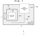
Fig. 1 is a view showing the arrangement of an X-ray generation apparatus according to an embodiment; -
Fig. 2 is a view schematically showing the outer appearance of a metal container or an electric component according to the embodiment; -
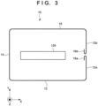
Fig. 3 is a view showing a section obtained by cutting the metal container or the electric component shown inFig. 2 along a predetermined X-Y plane; -
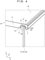
Fig. 4 is a view showing a part of a section obtained by cutting the metal container or the electric component shown inFig. 2 along a predetermined X-Z plane; -
Fig. 5 is a view showing a part of the section obtained by cutting the metal container or the electric component shown inFig. 2 along the predetermined X-Y plane; -
Fig. 6 is a view schematically showing a side wall portion before processing, or the developed state of the side wall portion; -
Fig. 7 is a view exemplarily showing the shape or processing method of a side wall member or a plate member; -
Fig. 8 is a view exemplarily showing the shape or processing method of the side wall member or the plate member; and -
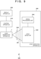
Fig. 9 is a view showing the arrangement of an X-ray imaging apparatus according to the embodiment. - Hereinafter, embodiments will be described in detail with reference to the attached drawings. Note, the following embodiments are not intended to limit the scope of the claimed invention. Multiple features are described in the embodiments, but limitation is not made to an invention that requires all such features, and multiple such features may be combined as appropriate. Furthermore, in the attached drawings, the same reference numerals are given to the same or similar configurations, and redundant description thereof is omitted.
- In this specification, terms expressing the direction or position, such as "up" and "down", are terms for expressing the relative position when observing a structure such as a metal container (to be described below) arranged with a given posture. The terms do not exclude arrangement of the structure with another posture.
-
Fig. 1 shows the arrangement of anX-ray generation apparatus 1 according to an embodiment. TheX-ray generation apparatus 1 can include anX-ray generation tube 110, an electric component EC, an accommodating container (or outer container) 100 accommodating theX-ray generation tube 110 and the electric component EC, and a second electric component (not shown). TheX-ray generation tube 110 can be accommodated in theaccommodating container 100 such that one surface or a part of theX-ray generation tube 110 is exposed to the external space. The electric component EC can include anelectric circuit 120, and a metal container MC covering theelectric circuit 120. In an example, theaccommodating container 100 can be formed of an electric conductor, and can be grounded. The ground terminal of theelectric circuit 120 can be electrically connected to theaccommodating container 100 via acable 131. The positive electrode terminal of theelectric circuit 120 can be connected to the positive electrode terminal of an external power supply via a cable 132. The second electric component (not shown) can be accommodated in theaccommodating container 100, and arranged outside the metal container MC. The second electric component can be, for example, a Cockcroft circuit or the like. - The
electric circuit 120 can be configured to drive theX-ray generation tube 110. Theelectric circuit 120 can generate one or a plurality of negative drive potentials for driving theX-ray generation tube 110 by receiving a voltage supplied through the cable 132. The one or plurality of negative drive potentials can be supplied to theX-ray generation tube 110 via acable 133. TheX-ray generation tube 110 can be formed as an anode grounding type, and the anode of theX-ray generation tube 110 can be electrically connected to theaccommodating container 100. The negative potential generated by theelectric circuit 120 can be supplied to the cathode of theX-ray generation tube 110. Theelectric circuit 120 can generate, for example, a potential difference of 100 kV (for example, -100 kV). The metal container MC can be applied with, for example, a negative potential (for example, -100 kV) of the maximum absolute value generated by theelectric circuit 120. - The internal space of the accommodating
container 100 can be filled with aninsulating liquid 150 such as insulating oil. Due to heat generated by theelectric circuit 120, the insulatingliquid 150 is convected in the internal space of theaccommodating container 100. Such convection can cause generation of noise, but the metal container MC can block transmission of the noise to theelectric circuit 120. In order to prevent discharge between the metal container MC and theaccommodating container 100 or the second electric component, the metal container MC can have a special structure to be described below. The electric component EC including the metal container MC having such the structure can also be used for applications other than the X-ray generation apparatus. -
Fig. 2 schematically shows the outer appearance of the metal container MC or the electric component EC according to the embodiment.Fig. 2 shows an XYZ coordinate system, and directions inFigs. 3 to 5 follow the XYZ coordinate system inFig. 2 .Fig. 3 shows a section obtained by cutting the metal container MC or the electric component EC shown inFig. 2 along a predetermined X-Y plane.Fig. 4 shows a part of a section obtained by cutting the metal container MC or the electric component EC shown inFig. 2 along a predetermined X-Z plane.Fig. 5 shows a part of the section obtained by cutting the metal container MC or the electric component EC shown inFig. 2 along the predetermined X-Y plane. - The metal container MC can include a
side wall portion 10 surrounding theelectric circuit 120, and closing portions (atop plate 20 and a bottom plate 30) respectively forming end surfaces (atop surface 22 and a bottom surface 32) of the metal container MC while coveringend portions 10e of theside wall portion 10. Here, a description will be given assuming that the closing portions (thetop plate 20 and the bottom plate 30) respectively forming the end surfaces (thetop surface 22 and the bottom surface 32) have similar features. However, one of the closing portions may have the features. - As exemplarily shown in
Fig. 4 , the exposed surface (in other words, outer surface) of the outer peripheral portion of each of the closing portions (thetop plate 20 and the bottom plate 30) exposed to the outside of the metal container MC can have a roundness in a section (for example, X-Z section) perpendicular to the end surfaces (thetop surface 22 and the bottom surface 32). This is useful for relaxing concentration of an electric field, and preventing discharge between the metal container MC and theaccommodating container 100 or the second electric component. - As exemplarily shown in
Fig. 4 , the outer peripheral portion of thetop plate 20 serving as the first closing portion can include a groove G that accepts theend portion 10e of theside wall portion 10. Theend portion 10e of theside wall portion 10 can include an edge surface ES that faces a bottom surface B of the groove G, and an end portion outer surface EOS corresponding to the outer surface of theside wall portion 10 in the vicinity of the edge surface ES. The outer peripheral portion of thetop plate 20 serving as the closing portion can include a bent portion F that faces the end portion outer surface EOS of theside wall portion 10. The bent portion F can have an R-processed shape. Thetop plate 20 serving as the closing portion can include a thick portion T1 and a thin portion T2 surrounding the thick portion T1. The thickness of the thin portion T2 is smaller than the thickness of thethick portion T 1. The step difference between the thick portion T1 and the thin portion T2 can form awall surface S 1, which is one of two wall surfaces S1 and S2 defining the groove G, and the bent portion F can form the wall surface S2, which is the other of the two wall surfaces S1 and S2. Such the arrangement is useful for hiding the corner portion such as theend portion 10e of theside wall portion 10 from the external space of the metal container MC, thereby relaxing concentration of the electric field. Such the arrangement is also useful for hiding the corner portion such as theend portion 10e of theside wall portion 10 from the internal space of the metal container MC, thereby relaxing concentration of the electric field. - Although not shown, the
bottom plate 30 serving as the second closing portion can also have the features similar to those of thetop plate 20 serving as the first closing portion. That is, thebottom plate 30 serving as the second closing portion forms thesecond end surface 32 of the metal container MC while covering the second end portion (lower end) of theside wall portion 10. The exposed surface of the outer peripheral portion of thebottom plate 30 serving as the second closing portion exposed to the outside of the metal container MC can have a roundness in a section perpendicular to thesecond end surface 32. The outer peripheral portion of thebottom plate 30 serving as the second closing portion can include the second groove that accepts the second end portion (lower end) of theside wall portion 10. The second end portion (lower end) of theside wall portion 10 can include the second edge surface that faces the bottom surface of the second groove, and the second end portion outer surface corresponding to the outer surface of theside wall portion 10 in the vicinity of thesecond edge surface 32. The outer peripheral portion of thebottom plate 30 serving as the second closing portion can include the second bent portion that faces the second end portion outer surface of theside wall portion 10. Thebottom plate 30 serving as the second closing portion can include the second thick portion and the second thin portion surrounding the second thick portion. The step difference between the second thick portion and the second thin portion can form one of two second wall surfaces defining the second groove, and the second bent portion can form the other of the two second wall surfaces. -
Fig. 6 schematically shows theside wall portion 10 before processing. In another viewpoint,Fig. 6 schematically shows the developed state of theside wall portion 10. Theside wall portion 10 can have a structure obtained by bending a plate member having two sets of opposite sides so as to form a rectangular tubular shape in which one set ofopposite sides Figs. 3 and5 , the exposed surface of the outer surface of theside wall portion 10 exposed to the outside of the metal container MC can have roundnesses in a section parallel to the end surfaces (thetop surface 22 and the bottom surface 32). The one set ofopposite sides bent shapes Figs. 3 and5 , each of the hemming-bent shapes - The
cables opposite sides side wall portion 10, thetop plate 20, and thebottom plate 30, and thecables - The hemming-bent shape is merely an example of the shape having a roundness. The shape having a roundness can be selected from various shapes such as a shape formed by curling processing exemplarily shown in
Fig. 8 . When bending the end portion of the plate member toward the inside of the metal container MC, the bending angle is preferably equal to or larger than 90°. In the case of hemming bending, the bending angle is 180°. When forming theside wall portion 10 by processing the plate member, the plate member may be processed such that the opposite sides (one end and the other end) of the plate member engage each other. For example, as exemplarily shown inFig. 7 , hemming bending can be performed while making the opposite sides (one end and the other end) of the plate member engage each other. In this manner, by processing the shape also having a roundness toward the inside of the metal container MC, it is possible to prevent discharge between the metal container MC and the electric circuit provided inside the metal container MC and having a potential difference with respect to the metal container MC. The processing as described above may be understood as processing for the exposed surface corresponding to the inner surface of theside wall portion 10 exposed to the inside of the metal container MC to have a roundness in the section parallel to the end surfaces (thetop surface 22 and the bottom surface 32). - In the example shown in
Figs. 2 to 5 , theside wall portion 10 has the rectangular tubular shape formed fromfirst surfaces second surface 13, athird surface 14, and afourth surface 15, which can be formed from one plate member. However, theside wall portion 10 may be formed from a plurality of members. Theside wall portion 10 may have a non-rectangular polygonal tubular shape, a cylindrical shape, or another shape. -
Fig. 9 shows the arrangement of anX-ray imaging apparatus 200 according to the embodiment. TheX-ray imaging apparatus 200 can include theX-ray generation apparatus 1, and anX-ray detection apparatus 240 that detects X-rays XR emitted from theX-ray generation apparatus 1 and transmitted through anobject 230. TheX-ray imaging apparatus 200 may further include acontrol apparatus 210 and adisplay apparatus 220. TheX-ray detection apparatus 240 can include anX-ray detector 242 and asignal processing unit 244. Thecontrol apparatus 210 can control theX-ray generation apparatus 1 and theX-ray detection apparatus 240. TheX-ray detector 242 detects or captures the X-rays XR emitted from theX-ray generation apparatus 1 and transmitted through theobject 230. Thesignal processing unit 244 can process a signal output from theX-ray detector 242, and supply the processed signal to thecontrol apparatus 210. Based on the signal supplied from thesignal processing unit 244, thecontrol apparatus 210 causes thedisplay apparatus 220 to display an image. - 1: X-ray generation apparatus, 100: accommodating container, 110: X-ray generation tube, 120: electric circuit, 131, 132, 133: cable, 150: insulating liquid, EC: electric component, MC: metal container, 10: side wall portion, 20: top plate, 30: bottom plate
Claims (13)
- An electric component that comprises an electric circuit and a metal container covering the electric circuit, whereinthe metal container includes a side wall portion surrounding the electric circuit, and a closing portion forming an end surface of the metal container while covering an end portion of the side wall portion, andan exposed surface of an outer peripheral portion of the closing portion exposed to an outside of the metal container has a roundness in a section perpendicular to the end surface.
- The electric component according to claim 1, wherein the outer peripheral portion of the closing portion includes a groove that accepts the end portion of the side wall portion.
- The electric component according to claim 2, wherein the end portion of the side wall portion includes an edge surface that faces a bottom surface of the groove, and an end portion outer surface corresponding to an outer surface of the side wall portion in a vicinity of the edge surface,
the outer peripheral portion of the closing portion includes a bent portion that faces the end portion outer surface of the side wall portion. - The electric component according to claim 3, wherein the closing portion includes a thick portion and a thin portion surrounding the thick portion, and
a step difference between the thick portion and the thin portion forms one of two wall surfaces defining the groove, and the bent portion forms the other of the two wall surfaces. - The electric component according to any one of claims 1 to 4, further including
a second closing portion forming a second end surface of the metal container while covering a second end portion of the side wall portion,
wherein an exposed surface of an outer peripheral portion of the second closing portion exposed to the outside of the metal container has a roundness in a section perpendicular to the second end surface. - The electric component according to claim 5, wherein the outer peripheral portion of the second closing portion includes a second groove that accepts the second end portion of the side wall portion.
- The electric component according to claim 6, whereinthe second end portion of the side wall portion includes a second edge surface that faces a bottom surface of the second groove, and a second end portion outer surface corresponding to the outer surface of the side wall portion in a vicinity of the second edge surface, andthe outer peripheral portion of the second closing portion includes a second bent portion that faces the second end portion outer surface of the side wall portion.
- The electric component according to claim 7, whereinthe second closing portion includes a second thick portion and a second thin portion surrounding the second thick portion, anda step difference between the second thick portion and the second thin portion forms one of two second wall surfaces defining the second groove, and the second bent portion forms the other of the two second wall surfaces.
- The electric component according to any one of claims 1 to 8, wherein the side wall portion has a structure obtained by bending a plate member having two sets of opposite sides so as to form a tubular shape in which one set of opposite sides of the two sets of opposite sides face each other, and an exposed surface of an outer surface of the side wall portion exposed to the outside of the metal container has a roundness in a section parallel to the end surface.
- The electric component according to claim 9, wherein each of the one set of opposite sides of the two sets of opposite sides has a hemming-bent shape.
- The electric component according to claim 10, wherein the hemming-bent shape is a hemming-bent shape toward an inside of the metal container.
- An X-ray generation apparatus comprising:an electric component defined in any one of claims 1 to 11;an X-ray generation tube; andan accommodating container that accommodates the electric component and the X-ray generation tube,wherein the electric component is configured to drive the X-ray generation tube, andan internal space of the accommodating container is filled with an insulating liquid.
- An X-ray imaging apparatus comprising:an X-ray generation apparatus defined in claim 12; andan X-ray detector that detects X-rays emitted from the X-ray generation apparatus.
Applications Claiming Priority (1)
| Application Number | Priority Date | Filing Date | Title |
|---|---|---|---|
| PCT/JP2022/016708 WO2023188336A1 (en) | 2022-03-31 | 2022-03-31 | Electric component, x-ray generation device, and x-ray imaging device |
Publications (2)
| Publication Number | Publication Date |
|---|---|
| EP4395470A1 true EP4395470A1 (en) | 2024-07-03 |
| EP4395470A4 EP4395470A4 (en) | 2025-02-26 |
Family
ID=87654369
Family Applications (1)
| Application Number | Title | Priority Date | Filing Date |
|---|---|---|---|
| EP22935477.4A Pending EP4395470A4 (en) | 2022-03-31 | 2022-03-31 | ELECTRICAL COMPONENT, X-RAY GENERATING DEVICE AND X-RAY IMAGING DEVICE |
Country Status (7)
| Country | Link |
|---|---|
| US (1) | US11979970B2 (en) |
| EP (1) | EP4395470A4 (en) |
| JP (2) | JP7333884B1 (en) |
| KR (1) | KR102758352B1 (en) |
| CN (1) | CN118947224B (en) |
| TW (1) | TWI845225B (en) |
| WO (1) | WO2023188336A1 (en) |
Family Cites Families (16)
| Publication number | Priority date | Publication date | Assignee | Title |
|---|---|---|---|---|
| GB379332A (en) * | 1930-12-01 | 1932-08-23 | Continental Can Co | Improvements in cans or like metal containers |
| JPS5335368A (en) * | 1976-09-14 | 1978-04-01 | Ise Electronics Corp | Display tube and method of manufacturing same |
| JP3400471B2 (en) * | 1992-08-01 | 2003-04-28 | 東京エレクトロン株式会社 | Ion implanter |
| JP3367206B2 (en) * | 1994-05-16 | 2003-01-14 | 日新電機株式会社 | High voltage box for ion implanter |
| JP3497050B2 (en) * | 1996-10-04 | 2004-02-16 | オリジン電気株式会社 | High voltage generator for X-ray equipment |
| US6570962B1 (en) | 2002-01-30 | 2003-05-27 | Koninklijke Philips Electronics N.V. | X-ray tube envelope with integral corona shield |
| JP2007141595A (en) * | 2005-11-17 | 2007-06-07 | Hitachi Medical Corp | X-ray tube and x-ray device using it |
| JP4857017B2 (en) * | 2006-04-27 | 2012-01-18 | 日立オートモティブシステムズ株式会社 | Power converter |
| CN102595753B (en) * | 2012-01-06 | 2015-05-13 | 同方威视技术股份有限公司 | Radiation device installing box and X-ray generator |
| JP6214899B2 (en) * | 2012-03-30 | 2017-10-18 | 東芝電子管デバイス株式会社 | Rotating anode type X-ray tube unit and rotating anode type X-ray tube device |
| JP2015028909A (en) * | 2013-06-27 | 2015-02-12 | キヤノン株式会社 | Radiation generator and radiation imaging system using the same |
| JP2016162525A (en) | 2015-02-27 | 2016-09-05 | 東芝電子管デバイス株式会社 | X-ray tube device |
| JP2019173814A (en) * | 2018-03-27 | 2019-10-10 | 日立オートモティブシステムズ株式会社 | Cylinder device |
| KR102362008B1 (en) * | 2019-04-15 | 2022-02-14 | 캐논 아네르바 가부시키가이샤 | X-ray generator and X-ray imaging device |
| WO2021044525A1 (en) * | 2019-09-03 | 2021-03-11 | キヤノンアネルバ株式会社 | X-ray generator and x-ray imaging device |
| CN215972967U (en) * | 2021-09-18 | 2022-03-08 | 佛山市鹏威塑胶制品有限公司 | A waterproof sealing structure of an obliquely inserted plastic storage box |
-
2022
- 2022-03-31 EP EP22935477.4A patent/EP4395470A4/en active Pending
- 2022-03-31 WO PCT/JP2022/016708 patent/WO2023188336A1/en not_active Ceased
- 2022-03-31 JP JP2023515851A patent/JP7333884B1/en active Active
- 2022-03-31 CN CN202280094327.2A patent/CN118947224B/en active Active
- 2022-03-31 KR KR1020247035644A patent/KR102758352B1/en active Active
-
2023
- 2023-03-24 TW TW112111152A patent/TWI845225B/en active
- 2023-08-15 JP JP2023132320A patent/JP2023159250A/en active Pending
- 2023-11-10 US US18/506,276 patent/US11979970B2/en active Active
Also Published As
| Publication number | Publication date |
|---|---|
| TW202405852A (en) | 2024-02-01 |
| US11979970B2 (en) | 2024-05-07 |
| WO2023188336A1 (en) | 2023-10-05 |
| KR20240161695A (en) | 2024-11-12 |
| EP4395470A4 (en) | 2025-02-26 |
| KR102758352B1 (en) | 2025-01-23 |
| TWI845225B (en) | 2024-06-11 |
| CN118947224A (en) | 2024-11-12 |
| JP2023159250A (en) | 2023-10-31 |
| JPWO2023188336A1 (en) | 2023-10-05 |
| JP7333884B1 (en) | 2023-08-25 |
| CN118947224B (en) | 2026-01-13 |
| US20240080962A1 (en) | 2024-03-07 |
Similar Documents
| Publication | Publication Date | Title |
|---|---|---|
| EP3923312A1 (en) | X-ray generation device and x-ray imaging device | |
| US12177958B2 (en) | X-ray generating apparatus, X-ray imaging apparatus, and mold transformer | |
| EP4006950A1 (en) | X-ray generator and x-ray imaging device | |
| EP4395470A1 (en) | Electric component, x-ray generation device, and x-ray imaging device | |
| EP1950788B1 (en) | X-ray tube and x-ray source including same | |
| EP1944788B1 (en) | X-ray tube and x-ray source including same | |
| US20130308757A1 (en) | Electric potential control of high voltage insulation | |
| US9548182B2 (en) | Charged particle beam generating apparatus, charged particle beam apparatus, high voltage generating apparatus, and high potential apparatus | |
| JP3984942B2 (en) | Image display device and information display device | |
| WO2024194909A1 (en) | X-ray generation device and x-ray imaging system | |
| JP2014154255A (en) | Connector, wire harness, and holding member | |
| EP0708474B1 (en) | Cathode-ray tube display unit in which unwanted radiant electric field from face plate of cathode-ray tube is decreased | |
| EP1727181A1 (en) | Plasma display apparatus | |
| US20250120004A1 (en) | Cathode supply assembly | |
| US5430352A (en) | Alternating electric field diminishing structure for cathode ray tube device | |
| JP7430296B1 (en) | X-ray generator and X-ray imaging device | |
| JP6922540B2 (en) | Vehicle cable unit | |
| US12610460B2 (en) | Oil-air electrical feedthrough circuit board for high voltage generator | |
| CN223110225U (en) | Radiation source device and detection equipment | |
| CN223110226U (en) | Radiation source device and detection equipment | |
| KR20180032801A (en) | X-Ray Tube and X-Ray Generating Apparatus Comprising the Same | |
| JP2023169971A (en) | shield connector | |
| US8075340B2 (en) | Connector and display apparatus having the same | |
| JPH117911A (en) | Cathode ray tube device | |
| JP6088314B2 (en) | Vacuum feedthrough, vacuum equipment |
Legal Events
| Date | Code | Title | Description |
|---|---|---|---|
| STAA | Information on the status of an ep patent application or granted ep patent |
Free format text: STATUS: THE INTERNATIONAL PUBLICATION HAS BEEN MADE |
|
| PUAI | Public reference made under article 153(3) epc to a published international application that has entered the european phase |
Free format text: ORIGINAL CODE: 0009012 |
|
| STAA | Information on the status of an ep patent application or granted ep patent |
Free format text: STATUS: REQUEST FOR EXAMINATION WAS MADE |
|
| 17P | Request for examination filed |
Effective date: 20240326 |
|
| AK | Designated contracting states |
Kind code of ref document: A1 Designated state(s): AL AT BE BG CH CY CZ DE DK EE ES FI FR GB GR HR HU IE IS IT LI LT LU LV MC MK MT NL NO PL PT RO RS SE SI SK SM TR |
|
| RIC1 | Information provided on ipc code assigned before grant |
Ipc: H05K 5/04 20060101ALI20240913BHEP Ipc: G01N 23/083 20180101ALI20240913BHEP Ipc: G01N 23/04 20180101ALI20240913BHEP Ipc: H05G 1/06 20060101ALI20240913BHEP Ipc: H05G 1/02 20060101AFI20240913BHEP |
|
| A4 | Supplementary search report drawn up and despatched |
Effective date: 20250123 |
|
| RIC1 | Information provided on ipc code assigned before grant |
Ipc: H05K 5/04 20060101ALI20250117BHEP Ipc: G01N 23/083 20180101ALI20250117BHEP Ipc: G01N 23/04 20180101ALI20250117BHEP Ipc: H05G 1/06 20060101ALI20250117BHEP Ipc: H05G 1/02 20060101AFI20250117BHEP |
|
| DAV | Request for validation of the european patent (deleted) | ||
| DAX | Request for extension of the european patent (deleted) | ||
| STAA | Information on the status of an ep patent application or granted ep patent |
Free format text: STATUS: EXAMINATION IS IN PROGRESS |
|
| 17Q | First examination report despatched |
Effective date: 20251104 |