EP4395345A1 - Camera module - Google Patents
Camera module Download PDFInfo
- Publication number
- EP4395345A1 EP4395345A1 EP22861721.3A EP22861721A EP4395345A1 EP 4395345 A1 EP4395345 A1 EP 4395345A1 EP 22861721 A EP22861721 A EP 22861721A EP 4395345 A1 EP4395345 A1 EP 4395345A1
- Authority
- EP
- European Patent Office
- Prior art keywords
- substrate
- disposed
- support member
- sidewalls
- substrates
- Prior art date
- Legal status (The legal status is an assumption and is not a legal conclusion. Google has not performed a legal analysis and makes no representation as to the accuracy of the status listed.)
- Pending
Links
Images


Classifications
-
- G—PHYSICS
- G03—PHOTOGRAPHY; CINEMATOGRAPHY; ANALOGOUS TECHNIQUES USING WAVES OTHER THAN OPTICAL WAVES; ELECTROGRAPHY; HOLOGRAPHY
- G03B—APPARATUS OR ARRANGEMENTS FOR TAKING PHOTOGRAPHS OR FOR PROJECTING OR VIEWING THEM; APPARATUS OR ARRANGEMENTS EMPLOYING ANALOGOUS TECHNIQUES USING WAVES OTHER THAN OPTICAL WAVES; ACCESSORIES THEREFOR
- G03B17/00—Details of cameras or camera bodies; Accessories therefor
- G03B17/02—Bodies
- G03B17/12—Bodies with means for supporting objectives, supplementary lenses, filters, masks, or turrets
-
- B—PERFORMING OPERATIONS; TRANSPORTING
- B60—VEHICLES IN GENERAL
- B60R—VEHICLES, VEHICLE FITTINGS, OR VEHICLE PARTS, NOT OTHERWISE PROVIDED FOR
- B60R11/00—Arrangements for holding or mounting articles, not otherwise provided for
- B60R11/04—Mounting of cameras operative during drive; Arrangement of controls thereof relative to the vehicle
-
- G—PHYSICS
- G03—PHOTOGRAPHY; CINEMATOGRAPHY; ANALOGOUS TECHNIQUES USING WAVES OTHER THAN OPTICAL WAVES; ELECTROGRAPHY; HOLOGRAPHY
- G03B—APPARATUS OR ARRANGEMENTS FOR TAKING PHOTOGRAPHS OR FOR PROJECTING OR VIEWING THEM; APPARATUS OR ARRANGEMENTS EMPLOYING ANALOGOUS TECHNIQUES USING WAVES OTHER THAN OPTICAL WAVES; ACCESSORIES THEREFOR
- G03B30/00—Camera modules comprising integrated lens units and imaging units, specially adapted for being embedded in other devices, e.g. mobile phones or vehicles
-
- H—ELECTRICITY
- H04—ELECTRIC COMMUNICATION TECHNIQUE
- H04N—PICTORIAL COMMUNICATION, e.g. TELEVISION
- H04N23/00—Cameras or camera modules comprising electronic image sensors; Control thereof
- H04N23/50—Constructional details
- H04N23/51—Housings
-
- H—ELECTRICITY
- H04—ELECTRIC COMMUNICATION TECHNIQUE
- H04N—PICTORIAL COMMUNICATION, e.g. TELEVISION
- H04N23/00—Cameras or camera modules comprising electronic image sensors; Control thereof
- H04N23/50—Constructional details
- H04N23/54—Mounting of pick-up tubes, electronic image sensors, deviation or focusing coils
-
- H—ELECTRICITY
- H04—ELECTRIC COMMUNICATION TECHNIQUE
- H04N—PICTORIAL COMMUNICATION, e.g. TELEVISION
- H04N23/00—Cameras or camera modules comprising electronic image sensors; Control thereof
- H04N23/50—Constructional details
- H04N23/55—Optical parts specially adapted for electronic image sensors; Mounting thereof
-
- H—ELECTRICITY
- H04—ELECTRIC COMMUNICATION TECHNIQUE
- H04N—PICTORIAL COMMUNICATION, e.g. TELEVISION
- H04N23/00—Cameras or camera modules comprising electronic image sensors; Control thereof
- H04N23/57—Mechanical or electrical details of cameras or camera modules specially adapted for being embedded in other devices
Definitions
- the present embodiment is intended to provide a camera module that minimizes the reduction of component mounting space in a multiple substrate stack structure.
- the present embodiment is intended to provide a camera module that can minimize process time because the process is simplified with a hook fastening structure.
- the camera module may comprise: a first body on which a lens is disposed; a second body coupling with the first body; a plurality of substrates being disposed between the first body and the second body; and a support member for fixing the plurality of substrates so that the substrates are spaced apart in an optical axis direction, wherein the support member includes sidewalls being disposed between different substrates and extension parts being extended from the sidewalls.
- At least one substrate among the plurality of substrates may include a rib being in contact with the sidewalls of the support member on a side surface not being formed with the protruded part.
- the support member may include a connecting part for connecting two adjacent sidewalls and being perpendicular to the sidewalls.
- the plurality of substrates includes first to third substrates sequentially adjacent to the first body, and the support member may include: a first support member being disposed between the first substrate and the second substrate; and a second support member being disposed between the second substrate and the third substrate.
- the sidewalls of the first support member and the sidewalls of the second support member may be disposed to be overlapped with each other in an optical axis direction.
- the second substrate and the third substrate may have the same shape and size.
- the extension part may comprise: a first surface being extended from the sidewalls to form an inclined surface; a second surface being extended from the first surface and including a hole; and a third surface being extended from the second surface to form an inclined surface.
- substrate bending that may occur during the coupling process between pluralities of substrates can be prevented.
- first, second, A, B, (a), and (b) may be used. These terms are merely intended to distinguish the components from other components, and the terms do not limit the nature, order or sequence of the components.
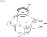
- FIG. 1 is a perspective view of a camera module according to an embodiment of the present invention
- FIG. 2 is an exploded perspective view of a camera module according to an embodiment of the present invention
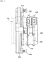
- FIG. 3 is a cross-sectional view of a camera module according to an embodiment of the present invention
- FIG. 4 is an enlarged perspective view of an internal structure of a camera module according to an embodiment of the present invention
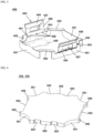
- FIG. 5 illustrates a support member of a camera module according to an embodiment of the present invention
- FIG. 6 illustrates a substrate of a camera module according to an embodiment of the present invention
- FIG. 7(a) illustrates a conventional substrate arrangement structure
- FIG. 7(b) illustrates a substrate arrangement structure according to an embodiment of the present invention.
- a lens may be disposed in the first body 210.
- the first body 210 may be referred to as any one among a front housing, a front body, an upper housing, and a first housing.
- the first body 210 may include a lens.
- the first body 210 may include a lens barrel.
- a lens barrel may be disposed on one side of the opening of the first body 210.
- the lens barrel can accommodate a lens inside.
- a lens may be disposed in the hole of the lens barrel.
- the inner surface of the hole of the lens barrel may be formed in a size and shape corresponding to the outer circumferential shape of the lens.
- the lens barrel and lens may be formed integrally.
- the first body 210, the lens barrel, and the lens may be formed as one body.
- the first body 210, the lens barrel, and the lens may be formed separately.
- the second body 220 may be referred to as any one among a rear housing, a rear body, a lower housing, and a second housing.
- the second body 220 may be formed in a square shape with an open upper part.
- the second body 220 may be formed of a metal material.
- the second body 220 may be disposed below the first body 210.
- the second body 220 may be coupled with the first body 210.
- the second body 220 may form an internal space through the coupling with the first body 210.
- the second body 220 may include a space part whose upper surface is open.
- the lower surface of the first body 210 may include a first boss part 211 being in contact with one surface of the first substrate 310.
- An adhesive member 702 may be disposed between one surface of the first substrate 310 and the first boss part 211.
- the adhesive member 702 may be formed in a strip shape corresponding to the shape of the edge of one surface of the first substrate 310.
- the lower surface of the first body 210 may include a second boss part 212 being in contact with the second body 220.
- the lower surface of the first body 210 may include: a concave part between the first boss part 211 being in contact with one surface of the first substrate 310; and the second boss part 212 being in contact with the second body 220.
- the concave part may be a space being formed by the first boss part 211 and the second boss part 212 being protruded from a lower surface of the first body 210.
- the plurality of substrates 300 may include first to third substrates 310, 320, and 330 sequentially disposed adjacent to the first body 210.
- the first substrate 310 is a substrate being disposed closest to the lens, and an image sensor 701 may be mounted on an upper surface of the first substrate 310.
- a first heat dissipation member 703 may be disposed on a lower surface of the first substrate 310.
- the first heat dissipation member 703 may allow heat being generated from the image sensor 701 to be discharged.
- the first heat dissipation member 703 may be disposed on a lower surface of the second substrate 320.
- the plurality of substrates 300 may be electrically connected to each other by flexible substrates being connected to side surfaces.
- the first flexible substrate 341 is fixed to one end of the adhesive member 702, so that the first substrate 310 and the second substrate 320 can be electrically connected to each other.
- the second flexible substrate 342 is fixed to the second heat dissipation member 704, so that the second substrate 320 and the third substrate 330 can be electrically connected to each other.
- the first flexible substrate 341 may be connected to the side surface of the first substrate 310 and the side surface of the second substrate 320; and the second flexible substrate 342 may be connected to the side surface of the second substrate 320 and the side surface of the third substrate 330.
- the first flexible substrate 341 and the second flexible substrate 342 may be disposed on opposite sides of each other to avoid mutual interference.
- It may include a support member 400 that fixes the plurality of substrates 300 so as to be spaced apart from one another in an optical axis direction.
- the support member 400 may include a first support member 410 and a second support member 420.
- the first support member 410 and the second support member 420 may be formed in the same shape.
- the first support member 410 may be disposed on a lower surface of the first substrate 310.
- the first support member 410 may be disposed between the first substrate 310 and the second substrate 320.
- the second support member 420 may be disposed on a lower surface of the second substrate 320.
- the second support member 420 may be disposed between the second substrate 320 and the third substrate 330.
- the first support member 410 may support the first substrate 310 and the second substrate 320 while being spaced apart in an optical axis direction.
- the second support member 420 may support the second substrate 320 and the third substrate 330 while being spaced apart in an optical axis direction.
- the number of support members 400 may increase or decrease depending on the number of substrates being included in the camera module.
- the first support member 410 and the second support member 420 are distinguished depending on their arrangement locations, and their shapes may be the same.
- the following description of the support member 400 may be a description of each of the first support member 410 and the second support member 420.
- the support member 400 may include a plurality of sidewalls 401.
- the plurality of sidewalls 401 may include first sidewalls and second sidewalls being disposed to face each other, and third sidewalls and fourth sidewalls being connected to the first sidewalls and the second sidewalls and being disposed to face each other.
- a plurality of sidewalls 401 may be disposed to be spaced apart from each other.
- One end of the plurality of sidewalls 401 of the first support member 410 may be disposed to be in contact with a lower surface of the first substrate 310.
- One end of the plurality of sidewalls 401 of the second support member 420 may be disposed to be in contact with a lower surface of the second substrate 320.
- the plurality of sidewalls of the first support member 410 and the plurality of sidewalls of the second support member 420 may be disposed to be overlapped with each other in an optical axis direction.
- Each of the plurality of sidewalls of the first support member 410 and the plurality of sidewalls of the second support member 420 may be disposed on a same virtual line.
- the support member 400 may include a connecting part 402 connecting two adjacent sidewalls.
- the connecting part 402 may connect other ends of adjacent sidewalls 401 to one another.
- the connecting part 402 may connect the first sidewalls and the third sidewalls.
- the connecting part 402 may connect the first sidewalls and the fourth sidewalls.
- the connecting part 402 may connect the second sidewalls and the third sidewalls.
- the connecting part 402 may connect the second sidewalls and the fourth sidewalls.
- the connecting part 402 may be formed at four corners of the support member 400.
- the connecting part 402 may be disposed to be perpendicular to the sidewalls 401.
- the connecting part 402 may be formed in a plane parallel to the substrate.
- the connecting part 402 may be formed so that both end parts are perpendicular to each sidewall 401, and the center part may be formed to form an obtuse angle with both end parts.
- Each of the both side surfaces of the connecting part 402 may be formed of three surfaces forming obtuse angles to each other.
- Both side surfaces of the connecting part 402 may be formed as curved surfaces.
- the inner side surface of the connecting part 402 may be formed to be longer than the outer side surface.
- the connecting part 402 may be formed to correspond to the shape of the edge of the substrate.
- One surface of the connecting part 402 of the first support member 410 may be in contact with an upper surface of the second substrate 320.
- One surface of the connecting part 402 of the first support member 410 and the upper surface of the second substrate 320 may be fixed with an adhesive.
- One surface of the connecting part 402 of the second support member 420 may be in contact with an upper surface of the third substrate 330.
- One surface of the connecting part 402 of the second support member 420 and an upper surface of the third substrate 330 may be fixed with an adhesive.
- a groove being recessed inward may be formed at the connecting part of the connecting part 402 and each sidewall 401.
- the groove may be formed to increase the rigidity of the part where the connecting part 402 and the sidewalls 401 are connected.
- the groove may be formed in a shape where triangular shapes face each other.
- the groove may be formed in a shape where inclined surfaces being recessed inward face each other.
- the groove may be a shape being created by inwardly bending the part where the connecting part 420 and each sidewall 401 meet.
- Any one of the plurality of sidewalls 401 may include a grip part 409 being formed in an inward direction and perpendicular to the sidewalls.
- the grip part 409 may be formed in a circular shape with rounded ends at the center part of the sidewalls 401.
- the grip part 409 is a part for gripping the support member 400 during the injection process and can be removed during the camera module assembly process.
- the first support member 410 may include an extension part 403 being extended from the sidewalls 401.
- the extension part 403 may be formed by being extended in one direction from the other end of the sidewalls facing each other.
- the extension part 403 may be formed by being extended from the first sidewalls and the second sidewalls.
- the extension part 403 may be formed by being extended from the third sidewalls and the fourth sidewalls.
- the extension part 403 may comprise: a first surface 404 being extended from the other end of the sidewalls 401 to form an inclined surface in an outward direction; a second surface 405 being extended from the first surface 404 in a direction parallel to the sidewalls 401 and including a hole 407; and a third surface 406 being extended from the second surface 405 to form an inclined surface in an outward direction.
- the extension part 403 may further include a part being extended from the third surface 406 in a direction parallel to the sidewalls 401.
- the extension part 403 includes a first surface 404 forming an inclined surface, the substrate 300 being disposed on an upper side and a lower side of the support member 400 may be disposed to have the same size.
- the protruded part 302 of the substrate 300 may be inserted and fixed into the hole 407 formed in the second surface 405.
- the concave parts 303 being formed on both sides of the protruded part 302 of the substrate 300 may be disposed to be in contact with the second surface 405 of the extension part 403.
- the third surface 406 may serve as a guide to facilitate insertion of the substrate 300 when the substrate 300 is coupled to the support member 400 from an upper side to a lower side.
- the third surface 406 and the part being extended from the third surface 406 may be fixed by being in contact with an inner side surface of the second body 220.
- the plurality of substrates 300 may all be formed to have the same shape and size.
- the plurality of substrates 300 may be formed to have different shapes and sizes.
- the second substrate 320 and the third substrate 330 may be formed to have the same size and shape.
- the following description of the shape of the substrate may be a description of each of the first to third substrates 310, 320, and 330.
- the substrate 300 may include an avoidance part 301 in which four corner side surfaces are roundly recessed inward.
- the avoidance part 301 may be formed to avoid a part where the first body 210 and the second body 220 are screw-coupled.
- the substrate 300 may include a first side surface and a second side surface being disposed at an opposite side to each other, and a third side surface and a fourth side surface being disposed at an opposite side to each other and connecting the first side surface and the second side surface.
- a protruded part 302 being inserted into the hole 407 formed in the extension part 403 may be formed on a first side surface and a second side surface of the substrate 300.
- the protruded part 302 may be formed in a shape corresponding to the hole 407 formed in the extension part 403.
- a concave part 303 being recessed inward may be formed on both sides of the protruded part 302.
- the concave part 303 may be in contact with a part other than the hole 407 when the protruded part 302 is inserted into the hole 407 formed in the extension part 403.
- the concave part 303 may be disposed to be in contact with a part of the second surface 405 of the extension part 403 other than the hole 407.
- a rib 304 may be formed on a third side surface and a fourth side surface of the substrate 300.
- a protrusion 305 may be formed on both sides of the ribs 304.
- a flexible substrate 340 may be connected to the rib 304 of different substrates.
- the rib 304 of the substrate 300 may form a space so that the flexible substrate 340 being connected to the rib 304 is disposed inside the second body 220. Referring to FIG. 7(a) , in an existing substrate arrangement structure, the upper support member was disposed more inward than the lower support member in order to avoid mutual interference between the lower support member disposed between the first substrate and the second substrate and the upper support member disposed between the second substrate and the third substrate.
Landscapes
- Engineering & Computer Science (AREA)
- Physics & Mathematics (AREA)
- General Physics & Mathematics (AREA)
- Multimedia (AREA)
- Signal Processing (AREA)
- Mechanical Engineering (AREA)
- Studio Devices (AREA)
Abstract
Description
- The present embodiment relates to a camera module. More specifically, the present invention relates to a camera module that minimizes the reduction of component mounting space in a multiple substrate stack structure.
- In general, since camera modules are manufactured in small sizes and are applied to various IT devices such as camera phones, PDAs, smartphones, and other portable mobile communication devices, in recent years, the release of devices equipped with small camera modules is gradually increasing according to various preferences of consumers.
- Recently, due to the advancement and automation of vehicle parts, camera modules for image acquisition are being widely used. For such examples, there are camera modules being used in front and rear surveillance cameras, black boxes, and the like.
- In addition, as demands for driver convenience and safety increase in the automobile industry, a variety of new technologies are being applied. In particular, technology using cameras is being actively applied by converging with software technology.
- Meanwhile, recently, a structure is being studied in which a plurality of substrates being disposed inside the camera module of vehicle camera is provided for lamination. However, when fixing a plurality of substrates using screws, the area of the substrates where the screws are coupled becomes an unusable area, which causes a problem in that component mounting space is reduced. In addition, there is a problem that the time required for the manufacturing process increases due to the screw fastening operation. In addition, there is a problem in that there is a possibility of substrate bending occurring due to excessive torque when fastening screws.
- The present embodiment is intended to provide a camera module that minimizes the reduction of component mounting space in a multiple substrate stack structure. In addition, the present embodiment is intended to provide a camera module that can minimize process time because the process is simplified with a hook fastening structure.
- In order to solve the above technical problem, the camera module according to an embodiment of the present invention may comprise: a first body on which a lens is disposed; a second body coupling with the first body; a plurality of substrates being disposed between the first body and the second body; and a support member for fixing the plurality of substrates so that the substrates are spaced apart in an optical axis direction, wherein the support member includes sidewalls being disposed between different substrates and extension parts being extended from the sidewalls.
- The extension part may comprise: a first surface being extended from the extension part to form an inclined surface; a second surface being extended from the first surface and including a hole; and a third surface being extended from the second surface to form an inclined surface.
- A side surface among at least one of the plurality of substrates may include a protruded part coupling to the hole of the second surface of the extension part.
- At least one substrate among the plurality of substrates may include a rib being in contact with the sidewalls of the support member on a side surface not being formed with the protruded part.
- A part where the sidewalls and the first surface of the extension part are connected may include a plurality of grooves being formed by being recessed.
- The support member may include a connecting part for connecting two adjacent sidewalls and being perpendicular to the sidewalls.
- The plurality of substrates includes first to third substrates sequentially adjacent to the first body, and the support member may include: a first support member being disposed between the first substrate and the second substrate; and a second support member being disposed between the second substrate and the third substrate.
- The sidewalls of the first support member and the sidewalls of the second support member may be disposed to be overlapped with each other in an optical axis direction.
- The second substrate and the third substrate may have the same shape and size.
- In order to solve the above technical problem, a camera module according to another embodiment of the present invention comprises: a first body on which a lens is disposed; a second body being coupled to the first body; first to third substrates being disposed between the first body and the second body; and a first support member being disposed between the first substrate and the second substrate; and a second support member being disposed between the second substrate and the third substrate, wherein the first and second support members may include sidewalls being disposed between different substrates and an extension part being extended from the sidewalls.
- The extension part may comprise: a first surface being extended from the sidewalls to form an inclined surface; a second surface being extended from the first surface and including a hole; and a third surface being extended from the second surface to form an inclined surface.
- In a part where the sidewalls and the first surface of the extension part are connected, a plurality of grooves being formed by being recessed may be included.
- An automobile according to an embodiment of the present invention comprises: a vehicle body; a door being mounted in the vehicle body; a display unit being disposed inside the vehicle body; and the camera module, wherein the camera module is disposed in at least one of the vehicle body and the door and can be electrically connected to the display unit.
- Through the present embodiment, the reduction of a component mounting space can be minimized despite the stacked structure of multiple substrates. In particular, compared to a screw-based coupling structure, a wider space for component mounting can be secured.
- In addition, the process becomes simplified due to the hook fastening structure so that the process time is minimized, thereby enhancing workability and productivity.
- In addition, substrate bending that may occur during the coupling process between pluralities of substrates can be prevented.
- In addition, it can prevent the substrate from shaking when the camera module vibrates.
-
-
FIG.1 is a perspective view of a camera module according to an embodiment of the present invention. -
FIG. 2 is an exploded perspective view of a camera module according to an embodiment of the present invention. -
FIG. 3 is a cross-sectional view of a camera module according to an embodiment of the present invention. -
FIG. 4 is an enlarged perspective view of an internal structure of a camera module according to an embodiment of the present invention. -
FIG. 5 illustrates a support member of a camera module according to an embodiment of the present invention. -
FIG. 6 illustrates a substrate of a camera module according to an embodiment of the present invention. -
FIG. 7(a) illustrates a conventional substrate arrangement structure, andFIG. 7(b) illustrates a substrate arrangement structure according to an embodiment of the present invention. - Hereinafter, preferred embodiments of the present invention will be described in detail with reference to the accompanying drawings.
- However, the technical idea of the present invention is not limited to some embodiments to be described, but may be implemented in various forms, and inside the scope of the technical idea of the present invention, one or more of the constituent elements may be selectively combined or substituted between embodiments.
- In addition, the terms (including technical and scientific terms) used in the present embodiments, unless explicitly defined and described, can be interpreted as a meaning that can be generally understood by a person skilled in the art, and commonly used terms such as terms defined in the dictionary may be interpreted in consideration of the meaning of the context of the related technology.
- In addition, terms used in the present specification are for describing embodiments and are not intended to limit the present invention.
- In the present specification, the singular form may include the plural form unless specifically stated in the phrase, and when described as "at least one (or more than one) of A and B and C", it may include one or more of all combinations that can be combined with A, B, and C.
- In addition, in describing the components of the present embodiment, terms such as first, second, A, B, (a), and (b) may be used. These terms are merely intended to distinguish the components from other components, and the terms do not limit the nature, order or sequence of the components.
- And, when a component is described as being 'connected', 'coupled' or 'interconnected' to another component, the component is not only directly connected, coupled or interconnected to the other component, but may also include cases of being 'connected', 'coupled', or 'interconnected' due that another component between that other components.
- In addition, when described as being formed or disposed in "on (above)" or "below (under)" of each component, "on (above)" or "below (under)" means that it includes not only the case where the two components are directly in contact with, but also the case where one or more other components are formed or disposed between the two components. In addition, when expressed as "on (above)" or "below (under)", the meaning of not only an upward direction but also a downward direction based on one component may be included.
- The 'optical axis direction' used below is defined as the optical axis direction of the lens. Meanwhile, 'optical axis direction' may correspond to such as 'up and down direction', 'z-axis direction', and the like.
- Hereinafter, the configuration of a camera module according to an embodiment of the present invention will be described with reference to the drawings.
-
FIG. 1 is a perspective view of a camera module according to an embodiment of the present invention;FIG. 2 is an exploded perspective view of a camera module according to an embodiment of the present invention;FIG. 3 is a cross-sectional view of a camera module according to an embodiment of the present invention;FIG. 4 is an enlarged perspective view of an internal structure of a camera module according to an embodiment of the present invention;FIG. 5 illustrates a support member of a camera module according to an embodiment of the present invention;FIG. 6 illustrates a substrate of a camera module according to an embodiment of the present invention; andFIG. 7(a) illustrates a conventional substrate arrangement structure, andFIG. 7(b) illustrates a substrate arrangement structure according to an embodiment of the present invention. - The camera module according to an embodiment of the present invention may be a vehicle camera module. The camera module may be coupled to the vehicle. The camera module may be used in at least one among a vehicle front camera, a side camera, a rear camera, an in-vehicle driver surveillance camera, and a black box. The camera module may be disposed at the front of the vehicle. The camera module may be disposed at the rear of the vehicle. The camera module may be disposed on the side of the vehicle. A vehicle may include a vehicle body in which a driver rides, a door being mounted on the car body, and a display unit being disposed inside the vehicle body. The camera module may be disposed in at least one of the vehicle body and the door. The camera module may be electrically connected to the display unit.
- A camera module according to an embodiment of the present invention may include a
body part 200, a plurality ofsubstrates 300, and asupport member 400. - The camera module may include a
body part 200. Thebody part 200 may include afirst body 210 and asecond body 220. - A lens may be disposed in the
first body 210. - More specifically, the
first body 210 may be referred to as any one among a front housing, a front body, an upper housing, and a first housing. Thefirst body 210 may include a lens. Thefirst body 210 may include a lens barrel. A lens barrel may be disposed on one side of the opening of thefirst body 210. The lens barrel can accommodate a lens inside. A lens may be disposed in the hole of the lens barrel. The inner surface of the hole of the lens barrel may be formed in a size and shape corresponding to the outer circumferential shape of the lens. The lens barrel and lens may be formed integrally. Thefirst body 210, the lens barrel, and the lens may be formed as one body. Thefirst body 210, the lens barrel, and the lens may be formed separately. The lens may include a plurality of lenses. The lens may be aligned with animage sensor 701. The lens may be optically aligned with theimage sensor 701. The optical axis of the lens may coincide with the optical axis of theimage sensor 701. Thefirst body 210 may include an infrared filter (IR filter) being disposed between the lens and theimage sensor 701. - The
second body 220 may be coupled to a lower side of thefirst body 210. - More specifically, the
second body 220 may be referred to as any one among a rear housing, a rear body, a lower housing, and a second housing. Thesecond body 220 may be formed in a square shape with an open upper part. Thesecond body 220 may be formed of a metal material. Thesecond body 220 may be disposed below thefirst body 210. Thesecond body 220 may be coupled with thefirst body 210. Thesecond body 220 may form an internal space through the coupling with thefirst body 210. Thesecond body 220 may include a space part whose upper surface is open. - The lower surface of the
first body 210 may include afirst boss part 211 being in contact with one surface of thefirst substrate 310. Anadhesive member 702 may be disposed between one surface of thefirst substrate 310 and thefirst boss part 211. Theadhesive member 702 may be formed in a strip shape corresponding to the shape of the edge of one surface of thefirst substrate 310. The lower surface of thefirst body 210 may include asecond boss part 212 being in contact with thesecond body 220. The lower surface of thefirst body 210 may include: a concave part between thefirst boss part 211 being in contact with one surface of thefirst substrate 310; and thesecond boss part 212 being in contact with thesecond body 220. The concave part may be a space being formed by thefirst boss part 211 and thesecond boss part 212 being protruded from a lower surface of thefirst body 210. - A sealing
member 600 may be disposed between thefirst body 210 and thesecond body 220. A sealingmember 600 may be disposed in a space formed by thefirst boss part 211 and thesecond boss part 212. Foreign substances can be prevented from entering the internal space of thefirst body 210 and thesecond body 220 through the sealingmember 600. - The
first body 210 and thesecond body 220 may be coupled through ascrew 500. Thesecond body 220 may have a hole where thescrew 500 is coupled to the square corner. Thefirst body 210 and thesecond body 220 may be coupled with an adhesive. Thefirst body 210 and thesecond body 220 may be coupled with an epoxy. - The
second body 220 may include a connector lead-out part on the bottom surface. The connector lead-out part may be coupled to the bottom surface. The connector lead-out part may be disposed in a hole (not shown) in the bottom surface. The connector lead-out part may penetrate a hole in the bottom surface. A connector may be disposed inside the connector lead-out part. The connector lead-out part may be formed of a metal material. - A plurality of
substrates 300 may be disposed between thefirst body 210 and thesecond body 220. - More specifically, the plurality of
substrates 300 may be printed circuit substrates (PCBs). Electronic components may be mounted on at least one of the upper surface and the lower surface of each of the plurality ofsubstrates 300. The plurality ofsubstrates 300 may be rigid substrates. The plurality ofsubstrates 300 may be disposed so that the upper surface and the lower surface face each other. - The plurality of
substrates 300 may include first tothird substrates first body 210. Thefirst substrate 310 is a substrate being disposed closest to the lens, and animage sensor 701 may be mounted on an upper surface of thefirst substrate 310. A firstheat dissipation member 703 may be disposed on a lower surface of thefirst substrate 310. The firstheat dissipation member 703 may allow heat being generated from theimage sensor 701 to be discharged. The firstheat dissipation member 703 may be disposed on a lower surface of thesecond substrate 320. Thethird substrate 330 is a substrate being disposed closest to the bottom surface of thesecond body 220, a secondheat dissipation member 704 may be disposed on the bottom surface of thethird substrate 330, and a connector may be coupled thereto. The plurality ofsubstrates 300 may be electrically connected to a connector. This is merely an example, and various electronic components may be mounted on at least one of one side and the other side of the first tothird substrates third substrate 330 may be disposed to be spaced apart from the bottom surface of thesecond body 220. At least some of the side surfaces among the plurality ofsubstrates 300 may be in contact with an inner surface of thesecond body 220. The plurality ofsubstrates 300 may include additional substrates in addition to the first tothird substrates - The plurality of
substrates 300 may be electrically connected to each other by flexible substrates being connected to side surfaces. Referring toFIG. 2 , the firstflexible substrate 341 is fixed to one end of theadhesive member 702, so that thefirst substrate 310 and thesecond substrate 320 can be electrically connected to each other. The secondflexible substrate 342 is fixed to the secondheat dissipation member 704, so that thesecond substrate 320 and thethird substrate 330 can be electrically connected to each other. This is only an example, the firstflexible substrate 341 may be connected to the side surface of thefirst substrate 310 and the side surface of thesecond substrate 320; and the secondflexible substrate 342 may be connected to the side surface of thesecond substrate 320 and the side surface of thethird substrate 330. With respect to the side surface of thesecond substrate 320, the firstflexible substrate 341 and the secondflexible substrate 342 may be disposed on opposite sides of each other to avoid mutual interference. - It may include a
support member 400 that fixes the plurality ofsubstrates 300 so as to be spaced apart from one another in an optical axis direction. - More specifically, the
support member 400 may include afirst support member 410 and asecond support member 420. Thefirst support member 410 and thesecond support member 420 may be formed in the same shape. Thefirst support member 410 may be disposed on a lower surface of thefirst substrate 310. Thefirst support member 410 may be disposed between thefirst substrate 310 and thesecond substrate 320. Thesecond support member 420 may be disposed on a lower surface of thesecond substrate 320. Thesecond support member 420 may be disposed between thesecond substrate 320 and thethird substrate 330. Thefirst support member 410 may support thefirst substrate 310 and thesecond substrate 320 while being spaced apart in an optical axis direction. Thesecond support member 420 may support thesecond substrate 320 and thethird substrate 330 while being spaced apart in an optical axis direction. The number ofsupport members 400 may increase or decrease depending on the number of substrates being included in the camera module. - Hereinafter, with reference to
FIG. 5 , thesupport member 400 according to an embodiment of the present invention will be described. Thefirst support member 410 and thesecond support member 420 are distinguished depending on their arrangement locations, and their shapes may be the same. The following description of thesupport member 400 may be a description of each of thefirst support member 410 and thesecond support member 420. - The
support member 400 may include a plurality ofsidewalls 401. The plurality ofsidewalls 401 may include first sidewalls and second sidewalls being disposed to face each other, and third sidewalls and fourth sidewalls being connected to the first sidewalls and the second sidewalls and being disposed to face each other. A plurality ofsidewalls 401 may be disposed to be spaced apart from each other. - One end of the plurality of
sidewalls 401 of thefirst support member 410 may be disposed to be in contact with a lower surface of thefirst substrate 310. One end of the plurality ofsidewalls 401 of thesecond support member 420 may be disposed to be in contact with a lower surface of thesecond substrate 320. The plurality of sidewalls of thefirst support member 410 and the plurality of sidewalls of thesecond support member 420 may be disposed to be overlapped with each other in an optical axis direction. Each of the plurality of sidewalls of thefirst support member 410 and the plurality of sidewalls of thesecond support member 420 may be disposed on a same virtual line. - The
support member 400 may include a connectingpart 402 connecting two adjacent sidewalls. The connectingpart 402 may connect other ends ofadjacent sidewalls 401 to one another. The connectingpart 402 may connect the first sidewalls and the third sidewalls. The connectingpart 402 may connect the first sidewalls and the fourth sidewalls. The connectingpart 402 may connect the second sidewalls and the third sidewalls. The connectingpart 402 may connect the second sidewalls and the fourth sidewalls. The connectingpart 402 may be formed at four corners of thesupport member 400. - The connecting
part 402 may be disposed to be perpendicular to thesidewalls 401. The connectingpart 402 may be formed in a plane parallel to the substrate. The connectingpart 402 may be formed so that both end parts are perpendicular to eachsidewall 401, and the center part may be formed to form an obtuse angle with both end parts. Each of the both side surfaces of the connectingpart 402 may be formed of three surfaces forming obtuse angles to each other. Both side surfaces of the connectingpart 402 may be formed as curved surfaces. The inner side surface of the connectingpart 402 may be formed to be longer than the outer side surface. The connectingpart 402 may be formed to correspond to the shape of the edge of the substrate. - One surface of the connecting
part 402 of thefirst support member 410 may be in contact with an upper surface of thesecond substrate 320. One surface of the connectingpart 402 of thefirst support member 410 and the upper surface of thesecond substrate 320 may be fixed with an adhesive. One surface of the connectingpart 402 of thesecond support member 420 may be in contact with an upper surface of thethird substrate 330. One surface of the connectingpart 402 of thesecond support member 420 and an upper surface of thethird substrate 330 may be fixed with an adhesive. - A groove being recessed inward may be formed at the connecting part of the connecting
part 402 and eachsidewall 401. The groove may be formed to increase the rigidity of the part where the connectingpart 402 and thesidewalls 401 are connected. The groove may be formed in a shape where triangular shapes face each other. The groove may be formed in a shape where inclined surfaces being recessed inward face each other. The groove may be a shape being created by inwardly bending the part where the connectingpart 420 and eachsidewall 401 meet. - Any one of the plurality of
sidewalls 401 may include agrip part 409 being formed in an inward direction and perpendicular to the sidewalls. Thegrip part 409 may be formed in a circular shape with rounded ends at the center part of thesidewalls 401. Thegrip part 409 is a part for gripping thesupport member 400 during the injection process and can be removed during the camera module assembly process. - The
first support member 410 may include anextension part 403 being extended from thesidewalls 401. - More specifically, the
extension part 403 may be formed by being extended in one direction from the other end of the sidewalls facing each other. Theextension part 403 may be formed by being extended from the first sidewalls and the second sidewalls. Theextension part 403 may be formed by being extended from the third sidewalls and the fourth sidewalls. Theextension part 403 may comprise: afirst surface 404 being extended from the other end of thesidewalls 401 to form an inclined surface in an outward direction; asecond surface 405 being extended from thefirst surface 404 in a direction parallel to thesidewalls 401 and including ahole 407; and athird surface 406 being extended from thesecond surface 405 to form an inclined surface in an outward direction. Theextension part 403 may further include a part being extended from thethird surface 406 in a direction parallel to thesidewalls 401. - Since the
extension part 403 includes afirst surface 404 forming an inclined surface, thesubstrate 300 being disposed on an upper side and a lower side of thesupport member 400 may be disposed to have the same size. - The
protruded part 302 of thesubstrate 300 may be inserted and fixed into thehole 407 formed in thesecond surface 405. Theconcave parts 303 being formed on both sides of theprotruded part 302 of thesubstrate 300 may be disposed to be in contact with thesecond surface 405 of theextension part 403. Thethird surface 406 may serve as a guide to facilitate insertion of thesubstrate 300 when thesubstrate 300 is coupled to thesupport member 400 from an upper side to a lower side. Thethird surface 406 and the part being extended from thethird surface 406 may be fixed by being in contact with an inner side surface of thesecond body 220. - The plurality of
substrates 300 may all be formed to have the same shape and size. The plurality ofsubstrates 300 may be formed to have different shapes and sizes. Referring toFIG. 6 , thesecond substrate 320 and thethird substrate 330 may be formed to have the same size and shape. The following description of the shape of the substrate may be a description of each of the first tothird substrates - The
substrate 300 may include anavoidance part 301 in which four corner side surfaces are roundly recessed inward. Theavoidance part 301 may be formed to avoid a part where thefirst body 210 and thesecond body 220 are screw-coupled. Thesubstrate 300 may include a first side surface and a second side surface being disposed at an opposite side to each other, and a third side surface and a fourth side surface being disposed at an opposite side to each other and connecting the first side surface and the second side surface. Aprotruded part 302 being inserted into thehole 407 formed in theextension part 403 may be formed on a first side surface and a second side surface of thesubstrate 300. Theprotruded part 302 may be formed in a shape corresponding to thehole 407 formed in theextension part 403. - A
concave part 303 being recessed inward may be formed on both sides of theprotruded part 302. Theconcave part 303 may be in contact with a part other than thehole 407 when theprotruded part 302 is inserted into thehole 407 formed in theextension part 403. Theconcave part 303 may be disposed to be in contact with a part of thesecond surface 405 of theextension part 403 other than thehole 407. - A
rib 304 may be formed on a third side surface and a fourth side surface of thesubstrate 300. Aprotrusion 305 may be formed on both sides of theribs 304. Aflexible substrate 340 may be connected to therib 304 of different substrates. Therib 304 of thesubstrate 300 may form a space so that theflexible substrate 340 being connected to therib 304 is disposed inside thesecond body 220. Referring toFIG. 7(a) , in an existing substrate arrangement structure, the upper support member was disposed more inward than the lower support member in order to avoid mutual interference between the lower support member disposed between the first substrate and the second substrate and the upper support member disposed between the second substrate and the third substrate. In this case, there is a problem that the size of the third substrate is reduced compared to the first substrate and the second substrate. Referring toFIG. 7(b) , in a substrate arrangement structure according to the present invention, theextension part 403 of thesupport member 400 can be spaced apart and fixed in an optical axis direction as first tothird substrates 300 of the same size through thefirst surface 404 forming an inclined surface and thesecond surface 405 in which aprotruded part 302 of the side surface of the substrate is inserted and fixed. - A
groove 408 being recessed inward may be formed in a part where thesidewall 401 of thesupport member 400 and thefirst surface 404 of theextension part 403 are connected. Thegroove 408 may be formed to increase the rigidity of the part where thefirst surface 404 of theextension part 403 and thesidewalls 401 are connected. Thegroove 408 may be formed in a triangular shape facing each other. Thegroove 408 may be formed in a shape where inclined surfaces being recessed inward face each other. - Although embodiments of the present invention have been described above with reference to the attached drawings, those skilled in the art will understand that the present invention can be implemented in other specific forms without changing the technical idea or essential features. Therefore, the embodiments described above should be understood in all respects as illustrative and not restrictive.
Claims (10)
- A camera module comprising:a first body in which a lens is disposed;a second body coupling with the first body;a plurality of substrates being disposed between the first body and the second body;anda support member for fixing the plurality of substrates so that the substrates are spaced apart in an optical axis direction,wherein the support member includes sidewalls being disposed between different substrates and extension parts being extended from the sidewalls.
- The camera module according to claim 1,
wherein the extension part comprises: a first surface being extended from the extension part to form an inclined surface; a second surface being extended from the first surface and including a hole; and a third surface being extended from the second surface to form an inclined surface. - The camera module according to claim 2,
wherein a side surface among at least one of the plurality of substrates includes a protruded part coupling to the hole of the second surface of the extension part. - The camera module according to claim 3,
wherein at least one substrate among the plurality of substrates includes a rib being in contact with the sidewalls of the support member on a side surface not being formed with the protruded part. - The camera module according to claim 1,
wherein a part where the sidewalls and the first surface of the extension part are connected includes a plurality of grooves being formed by being recessed. - The camera module according to claim 1,
wherein the support member includes a connecting part for connecting two adjacent sidewalls and being perpendicular to the sidewalls. - The camera module according to claim 1,wherein the plurality of substrates includes first to third substrates sequentially adjacent to the first body, andwherein the support member includes: a first support member being disposed between the first substrate and the second substrate; and a second support member being disposed between the second substrate and the third substrate.
- The camera module according to claim 7,
wherein the sidewalls of the first support member and the sidewalls of the second support member are disposed to be overlapped with each other in an optical axis direction. - A camera module comprising:a first body on which a lens is disposed;a second body being coupled to the first body;first to third substrates being disposed between the first body and the second body;a first support member being disposed between the first substrate and the second substrate; anda second support member being disposed between the second substrate and the third substrate,wherein the first and second support members include sidewalls being disposed between different substrates and an extension part being extended from the sidewalls.
- The camera module according to claim 9,
wherein the extension part comprises: a first surface being extended from the sidewalls to form an inclined surface; a second surface being extended from the first surface and including a hole; and a third surface being extended from the second surface to form an inclined surface.
Applications Claiming Priority (2)
| Application Number | Priority Date | Filing Date | Title |
|---|---|---|---|
| KR1020210114182A KR20230031685A (en) | 2021-08-27 | 2021-08-27 | Camera module |
| PCT/KR2022/012679 WO2023027513A1 (en) | 2021-08-27 | 2022-08-24 | Camera module |
Publications (2)
| Publication Number | Publication Date |
|---|---|
| EP4395345A1 true EP4395345A1 (en) | 2024-07-03 |
| EP4395345A4 EP4395345A4 (en) | 2025-08-20 |
Family
ID=85321920
Family Applications (1)
| Application Number | Title | Priority Date | Filing Date |
|---|---|---|---|
| EP22861721.3A Pending EP4395345A4 (en) | 2021-08-27 | 2022-08-24 | CAMERA MODULE |
Country Status (5)
| Country | Link |
|---|---|
| US (1) | US20240377712A1 (en) |
| EP (1) | EP4395345A4 (en) |
| KR (1) | KR20230031685A (en) |
| CN (1) | CN117897960A (en) |
| WO (1) | WO2023027513A1 (en) |
Families Citing this family (2)
| Publication number | Priority date | Publication date | Assignee | Title |
|---|---|---|---|---|
| KR20250082891A (en) * | 2023-11-30 | 2025-06-09 | 엘지이노텍 주식회사 | Camera module |
| KR20250165116A (en) * | 2024-05-17 | 2025-11-25 | 엘지이노텍 주식회사 | Camera module |
Family Cites Families (7)
| Publication number | Priority date | Publication date | Assignee | Title |
|---|---|---|---|---|
| KR100982271B1 (en) * | 2008-10-30 | 2010-09-14 | 삼성전기주식회사 | Automotive Camera Module |
| KR101428842B1 (en) * | 2011-11-08 | 2014-08-08 | 엘지이노텍 주식회사 | Camera module for Vehicle |
| JP6768825B2 (en) * | 2016-03-16 | 2020-10-14 | ジェンテックス コーポレイション | Camera assembly with occluded image sensor circuit |
| KR102645861B1 (en) * | 2016-09-02 | 2024-03-11 | 엘지이노텍 주식회사 | Camera module and Camera for vehicle |
| EP3651445B1 (en) * | 2017-07-04 | 2021-10-27 | LG Innotek Co., Ltd. | Camera module |
| KR102483472B1 (en) * | 2018-01-30 | 2023-01-02 | 엘지이노텍 주식회사 | Camera for vehicle |
| KR102814812B1 (en) * | 2018-11-13 | 2025-05-29 | 엘지이노텍 주식회사 | Camera Module |
-
2021
- 2021-08-27 KR KR1020210114182A patent/KR20230031685A/en active Pending
-
2022
- 2022-08-24 CN CN202280058577.0A patent/CN117897960A/en active Pending
- 2022-08-24 US US18/686,956 patent/US20240377712A1/en active Pending
- 2022-08-24 WO PCT/KR2022/012679 patent/WO2023027513A1/en not_active Ceased
- 2022-08-24 EP EP22861721.3A patent/EP4395345A4/en active Pending
Also Published As
| Publication number | Publication date |
|---|---|
| CN117897960A (en) | 2024-04-16 |
| KR20230031685A (en) | 2023-03-07 |
| EP4395345A4 (en) | 2025-08-20 |
| WO2023027513A1 (en) | 2023-03-02 |
| US20240377712A1 (en) | 2024-11-14 |
Similar Documents
| Publication | Publication Date | Title |
|---|---|---|
| JP7698015B2 (en) | Circuit board fixing device for camera module and camera module | |
| KR102708474B1 (en) | Camera module | |
| KR102427350B1 (en) | Camera module and camera for vehicle | |
| EP4395345A1 (en) | Camera module | |
| US10444598B1 (en) | Camera module and portable electronic device | |
| US11726297B2 (en) | Camera module | |
| EP4395344A1 (en) | Camera module | |
| US12313967B2 (en) | Aperture module and camera module including the same | |
| EP4394500A1 (en) | Camera module | |
| EP4195642B1 (en) | Electronic device | |
| US12621550B2 (en) | Camera module | |
| US20250172855A1 (en) | Camera module | |
| US20230362466A1 (en) | Camera module | |
| KR101901709B1 (en) | Camera module | |
| KR20230009132A (en) | Camera module | |
| KR20190012339A (en) | Camera module and vehicle | |
| US11936969B2 (en) | Camera module | |
| US11438496B2 (en) | Multi-camera module | |
| CN216086782U (en) | Driving device, camera module and electronic equipment | |
| US20240340515A1 (en) | Camera module and image sensor module | |
| US12621553B2 (en) | Camera module | |
| US20260113524A1 (en) | Camera module | |
| CN223334724U (en) | Camera module | |
| US20260126705A1 (en) | Camera module | |
| US20240419055A1 (en) | Iris module and camera module including the same |
Legal Events
| Date | Code | Title | Description |
|---|---|---|---|
| STAA | Information on the status of an ep patent application or granted ep patent |
Free format text: STATUS: THE INTERNATIONAL PUBLICATION HAS BEEN MADE |
|
| PUAI | Public reference made under article 153(3) epc to a published international application that has entered the european phase |
Free format text: ORIGINAL CODE: 0009012 |
|
| STAA | Information on the status of an ep patent application or granted ep patent |
Free format text: STATUS: REQUEST FOR EXAMINATION WAS MADE |
|
| 17P | Request for examination filed |
Effective date: 20240227 |
|
| AK | Designated contracting states |
Kind code of ref document: A1 Designated state(s): AL AT BE BG CH CY CZ DE DK EE ES FI FR GB GR HR HU IE IS IT LI LT LU LV MC MK MT NL NO PL PT RO RS SE SI SK SM TR |
|
| DAV | Request for validation of the european patent (deleted) | ||
| DAX | Request for extension of the european patent (deleted) | ||
| REG | Reference to a national code |
Ref country code: DE Ref legal event code: R079 Free format text: PREVIOUS MAIN CLASS: H04N0023000000 Ipc: H04N0023510000 |
|
| A4 | Supplementary search report drawn up and despatched |
Effective date: 20250718 |
|
| RIC1 | Information provided on ipc code assigned before grant |
Ipc: H04N 23/51 20230101AFI20250714BHEP Ipc: H04N 23/54 20230101ALI20250714BHEP Ipc: H04N 23/57 20230101ALI20250714BHEP Ipc: G03B 17/12 20210101ALI20250714BHEP Ipc: G03B 30/00 20210101ALI20250714BHEP Ipc: B60R 11/04 20060101ALI20250714BHEP |