EP4395121A2 - Power system and method of operating a power system - Google Patents
Power system and method of operating a power system Download PDFInfo
- Publication number
- EP4395121A2 EP4395121A2 EP23217244.5A EP23217244A EP4395121A2 EP 4395121 A2 EP4395121 A2 EP 4395121A2 EP 23217244 A EP23217244 A EP 23217244A EP 4395121 A2 EP4395121 A2 EP 4395121A2
- Authority
- EP
- European Patent Office
- Prior art keywords
- power
- switch
- connection
- input
- converter
- Prior art date
- Legal status (The legal status is an assumption and is not a legal conclusion. Google has not performed a legal analysis and makes no representation as to the accuracy of the status listed.)
- Pending
Links
Images


Classifications
-
- H—ELECTRICITY
- H02—GENERATION; CONVERSION OR DISTRIBUTION OF ELECTRIC POWER
- H02J—ELECTRIC POWER NETWORKS; CIRCUIT ARRANGEMENTS OR SYSTEMS FOR SUPPLYING OR DISTRIBUTING ELECTRIC POWER; SYSTEMS FOR STORING ELECTRIC ENERGY
- H02J9/00—Circuit arrangements for emergency or stand-by power supply, e.g. for emergency lighting
- H02J9/04—Circuit arrangements for emergency or stand-by power supply, e.g. for emergency lighting in which the distribution system is disconnected from the normal source and connected to a standby source
- H02J9/06—Circuit arrangements for emergency or stand-by power supply, e.g. for emergency lighting in which the distribution system is disconnected from the normal source and connected to a standby source with automatic change-over, e.g. UPS systems
- H02J9/062—Circuit arrangements for emergency or stand-by power supply, e.g. for emergency lighting in which the distribution system is disconnected from the normal source and connected to a standby source with automatic change-over, e.g. UPS systems for AC powered loads
-
- H—ELECTRICITY
- H02—GENERATION; CONVERSION OR DISTRIBUTION OF ELECTRIC POWER
- H02J—ELECTRIC POWER NETWORKS; CIRCUIT ARRANGEMENTS OR SYSTEMS FOR SUPPLYING OR DISTRIBUTING ELECTRIC POWER; SYSTEMS FOR STORING ELECTRIC ENERGY
- H02J9/00—Circuit arrangements for emergency or stand-by power supply, e.g. for emergency lighting
- H02J9/04—Circuit arrangements for emergency or stand-by power supply, e.g. for emergency lighting in which the distribution system is disconnected from the normal source and connected to a standby source
- H02J9/06—Circuit arrangements for emergency or stand-by power supply, e.g. for emergency lighting in which the distribution system is disconnected from the normal source and connected to a standby source with automatic change-over, e.g. UPS systems
- H02J9/068—Electronic means for switching from one power supply to another power supply, e.g. to avoid parallel connection
Definitions
- At least one example in accordance with the present disclosure relates generally to backfeed protection.
- UPSs uninterruptible power supplies
- UPSs may be used to provide regulated, uninterrupted power for sensitive and/or critical loads, such as computer systems and other data-processing systems.
- Existing UPSs include online UPSs, offline UPSs, line-interactive UPSs, as well as others.
- UPSs may provide output power to a load. The output power may be derived from a primary source of power, such as a utility-mains source, and/or derived from a back-up source of power, such as an energy-storage device.
- references to "or” may be construed as inclusive so that any terms described using “or” may indicate any of a single, more than one, and all of the described terms.
- the term usage in the incorporated features is supplementary to that of this document; for irreconcilable differences, the term usage in this document controls.
- UPSs uninterruptible power supplies
- UPSs may be connected to multiple power sources.
- a UPS may be connected to a primary power source, such as a mains utility supply, and a secondary power source, such as an energy-storage device.
- a primary power source such as a mains utility supply
- a secondary power source such as an energy-storage device.
- the UPS may draw power from the primary power source to power one or more loads.
- the UPS may instead draw power from the secondary power source to power one or more loads.
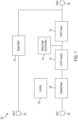
- FIG. 1 illustrates a block diagram of a power system 100 according to an example.
- the power system 100 may be or include a UPS.
- the power system 100 includes a first input 102, a second input 104, an output 106, a backfeed relay 108, an AC/DC converter 110, a DC/AC inverter 112, a backup power source interface 114, at least one bypass switch 116 ("bypass switch 116"), and at least one controller 118 ("controller 118").
- the first input 102 and the second input 104 may each be configured to be coupled to a primary power source, such as a utility mains.
- the output 106 may be configured to be coupled to at least one load ("load").
- the backup power source interface 114 may be configured to be coupled to at least one energy-storage device, such as a battery.
- the power system 100 may include additional components or features, such as a return connection, which are not illustrated for purposes of brevity.
- the power system 100 thus conditions the input power using the AC/DC converter 110 and/or the DC/AC inverter 112. Although the power received from the first input 102 may not have met the load power-quality requirements, the AC/DC converter 110 and/or the DC/AC inverter 112 may condition the power such that the power provided to the output 106 does meet the load power-quality requirements.
- Opening the backfeed relay 108 may reduce a chance of power being provided "back" to the primary power source via the first input 102 (that is, "fed back” to the first input 102) when power is not being drawn from the first input 102.
- the backfeed relay 108 were omitted, power received at the second input 104 and intended for the output 106 may undesirably pass through the DC/AC inverter 112 and the AC/DC converter 110 to the primary power source via the first input 102. Accordingly, the backfeed relay 108 advantageously reduces a chance of power being unintentionally fed back into the primary power source.
- the backfeed relay 108 it may be possible for power to arc across the backfeed relay 108 even when the backfeed relay is open. For example, if a voltage at a connection between the backfeed relay 108 and the AC/DC converter 110 (that is, an output terminal of the backfeed relay 108) is too high, arcing may occur. For this reason, it may be desirable to implement the backfeed relay 108 with a minimum airgap distance to reduce a chance of arcing.
- Examples of the disclosure provide systems and methods for reducing or eliminating a chance of arcing across a backfeed relay.
- a connection between an output terminal of a backfeed relay and an input converter is switchably coupled to a return connection by one or more safety switches when the backfeed relay is open.
- the one or more safety switches and the backfeed relay may be switched in a complementary fashion.
- the return connection may be maintained at a neutral voltage while the one or more safety switches are closed.
- the output terminal of the backfeed relay may be maintained at the neutral voltage by the safety switches when the backfeed relay is open.
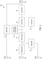
- FIG. 2 illustrates a block diagram of a power system 200 according to an example.
- the power system 200 is a multi-phase system, such as a three-phase system.
- FIG. 2 illustrates single connections between components for purposes of illustrative clarity.
- the power system 200 includes at least one first input power connection 202 ("first input power connection 202"), at least one second input power connection 204 ("second input power connection 204"), at least one output 206 ("output 206"), at least one backfeed switch 208 ("backfeed switch 208"), an AC/DC converter 210, a DC/AC inverter 212, a backup power source interface 214, at least one bypass switch 216 ("bypass switch 216"), at least one return connection 218 (“return connection 218”), at least one safety switch 220 (“safety switch 220”), at least one optional inverter switch 222 (“inverter switch 222”), and at least one control circuit 224 ("control circuit 224").
- the first input power connection 202 is coupled to the backfeed switch 208 and is configured to be coupled to a primary power source, such as a utility mains.
- the second input power connection 204 is coupled to the bypass switch 216 and is configured to be coupled to a primary power source, such as a utility mains, which may be the same power source or a different power source than that to which the first input power connection 202 is configured to be coupled.
- the output 206 is coupled to the bypass switch 216 and is configured to be coupled to one or more loads ("load"). In examples in which the optional inverter switch 222 is included, the output 206 is also coupled to the inverter switch 222. In examples in which the optional inverter switch 222 is omitted, the output 206 is coupled to the DC/AC inverter 212.
- the backfeed switch 208 which may include a backfeed relay or other backfeed switching device, is coupled to the first input power connection 202 at an input terminal and is coupled to the AC/DC converter 210 and the safety switch 220 at an output terminal.
- the backfeed switch 208 is also communicatively coupled to the control circuit 224.
- the AC/DC converter 210 is coupled to the backfeed switch 208 and the safety switch 220 at an input connection, and is coupled to the DC/AC inverter 212 and the backup power source interface 214 at a second connection.
- the AC/DC converter 210 may also be coupled to the return connection 218 at a third connection, which is not illustrated for purposes of clarity.
- the AC/DC converter 210 is also communicatively coupled to the control circuit 224.
- the inverter switch 222 is coupled to the DC/AC inverter 212 at a first connection, and is coupled to the output 206 at a second connection.
- the inverter switch 222 is also communicatively coupled to the control circuit 224.
- the control circuit 224 is communicatively coupled to the backfeed switch 208, the AC/DC converter 210, the DC/AC inverter 212, the backup power source interface 214, the bypass switch 216, the safety switch 220, and the inverter switch 222.
- the control circuit 224 may also include or be communicatively coupled to one or more sensors, such as one or more voltage sensors coupled to an input of the AC/DC converter 210.
- the control circuit 224 closes the safety switches 220a-220c. Closing the safety switches 220a-220c couples the AC/DC converter 210 and the output terminals of the backfeed switches 208a-208c to the return connection 218, which may be maintained at a neutral voltage in some examples. In this example, therefore, the output terminals of the backfeed switches 208a-208c are maintained at a neutral voltage. A chance of arcing across the backfeed switches 208a-208c from the output terminals to the input terminals is therefore reduced by maintaining the output terminals at a low (that is, neutral in this example) voltage.
- the SPDT switches may accomplish operation similar to the complementary control of the switches 208a-208c, 220a-220c inasmuch as the AC/DC converter 210 is coupled, via a respective pole, to either the input power connections 202a-202c or the return connection 218 via one of the two respective throws.
- control circuit 224 determines that the backfeed switch 208 is not to be opened (602 NO), then the process 400 continues to act 604. Otherwise, if the control circuit 224 determines that the backfeed switch 208 is to be opened (602 YES), then the process 600 continues to act 608.
- the control circuit 224 determines whether the voltage determined at act 612 exceeds a voltage threshold.
- the voltage threshold may be approximately 10 V in one example.
- the voltage determined at act 612 may be expected to be neutral, that is, zero. If the voltage is not at or near zero (for example, by exceeding 10 V) despite the switches 506, 508 being closed, the power system 500 may be experiencing a malfunction.
- one or more diodes in the power system 500 including, for example, PFC diodes in the AC/DC converter 210) may be malfunctioning and conducting a reverse current giving rise to the abnormally high voltage.
- the control circuit 224 determines that the voltage does not exceed the voltage threshold (614 NO)
- the process 600 returns to act 602. However, if the control circuit 224 determines that the voltage does exceed the voltage threshold (614 YES), then the process 600 continues to act 616.
- Clause 11 The method of clause 10, wherein the at least one safety switch includes at least one power-factor-correction (PFC) boost switch and the method further comprises providing, by the PFC boost switch, power-factor correction to input power received at the input power connection.
- PFC power-factor-correction
- Clause 13 The method of clause 10, wherein the power system includes an inverter coupled to the power converter, an output connection, and at least one inverter switch coupled between the inverter and the output connection, the method further comprising:
- a non-transitory computer-readable medium storing thereon sequences of computer-executable instructions for operating a power system having an input power connection, a return connection, a power converter having a converter input, a backfeed switch coupled between the input power connection and the converter input, and at least one safety switch coupled between the converter input and the return connection, the sequences of computer-executable instructions including instructions that instruct at least one processor to operate according to any of the above method clause 10-14.
Landscapes
- Business, Economics & Management (AREA)
- Emergency Management (AREA)
- Engineering & Computer Science (AREA)
- Power Engineering (AREA)
- Stand-By Power Supply Arrangements (AREA)
- Direct Current Feeding And Distribution (AREA)
Abstract
Description
- At least one example in accordance with the present disclosure relates generally to backfeed protection.
- Power devices, such as uninterruptible power supplies (UPSs), may be used to provide regulated, uninterrupted power for sensitive and/or critical loads, such as computer systems and other data-processing systems. Existing UPSs include online UPSs, offline UPSs, line-interactive UPSs, as well as others. UPSs may provide output power to a load. The output power may be derived from a primary source of power, such as a utility-mains source, and/or derived from a back-up source of power, such as an energy-storage device.
- Various aspects of at least one embodiment are discussed below with reference to the accompanying figures, which are not intended to be drawn to scale. The figures are included to provide an illustration and a further understanding of the various aspects and embodiments, and are incorporated in and constitute a part of this specification, but are not intended as a definition of the limits of any particular embodiment. The drawings, together with the remainder of the specification, serve to explain principles and operations of the described and claimed aspects and embodiments. In the figures, each identical or nearly identical component that is illustrated in various figures is represented by a like numeral. For purposes of clarity, not every component may be labeled in every figure. In the figures:
-
FIG. 1 illustrates a block diagram of a power system according to an example; -
FIG. 2 illustrates a block diagram of a power system according to another example; -
FIG. 3 illustrates a schematic diagram of an input section of a power system according to an example; -
FIG. 4 illustrates a process of operating components of an input section of a power system according to an example; -
FIG. 5 illustrates a schematic diagram of a power system according to an example; and -
FIG. 6 illustrates a process of operating a power system according to an example. - Examples of the methods and systems discussed herein are not limited in application to the details of construction and the arrangement of components set forth in the following description or illustrated in the accompanying drawings. The methods and systems are capable of implementation in other embodiments and of being practiced or of being carried out in various ways. Examples of specific implementations are provided herein for illustrative purposes only and are not intended to be limiting. In particular, acts, components, elements and features discussed in connection with any one or more examples are not intended to be excluded from a similar role in any other examples.
- Also, the phraseology and terminology used herein is for the purpose of description and should not be regarded as limiting. Any references to examples, embodiments, components, elements or acts of the systems and methods herein referred to in the singular may also embrace embodiments including a plurality, and any references in plural to any embodiment, component, element or act herein may also embrace embodiments including only a singularity. References in the singular or plural form are not intended to limit the presently disclosed systems or methods, their components, acts, or elements. The use herein of "including," "comprising," "having," "containing," "involving," and variations thereof is meant to encompass the items listed thereafter and equivalents thereof as well as additional items.
- References to "or" may be construed as inclusive so that any terms described using "or" may indicate any of a single, more than one, and all of the described terms. In addition, in the event of inconsistent usages of terms between this document and documents incorporated herein by reference, the term usage in the incorporated features is supplementary to that of this document; for irreconcilable differences, the term usage in this document controls.
- As discussed above, uninterruptible power supplies (UPSs) may be used to provide uninterrupted power to one or more loads. UPSs may be connected to multiple power sources. For example, a UPS may be connected to a primary power source, such as a mains utility supply, and a secondary power source, such as an energy-storage device. When power is available from the primary power source, the UPS may draw power from the primary power source to power one or more loads. When power is not available from the primary power source, the UPS may instead draw power from the secondary power source to power one or more loads.
- Some UPSs may include backfeed-protection circuitry, such as a backfeed relay. A backfeed relay may be configured to prevent power from being provided in the "wrong" direction. For example, the UPS may be configured to draw power from the primary power source, but not to provide power to the primary power source. Nonetheless, it may be possible (albeit undesirable) for the UPS to inadvertently provide power back to the primary power source, such as when power is not being drawn from the primary power source. A backfeed relay coupled to a connection from which the UPS connects to the primary power source may thus be open and non-conducting when power is not being drawn from the primary power source. The open backfeed relay may prevent backfeed power from being provided back to the primary power source.
- To illustrate the foregoing,
FIG. 1 illustrates a block diagram of apower system 100 according to an example. Thepower system 100 may be or include a UPS. Thepower system 100 includes afirst input 102, asecond input 104, anoutput 106, abackfeed relay 108, an AC/DC converter 110, a DC/AC inverter 112, a backuppower source interface 114, at least one bypass switch 116 ("bypass switch 116"), and at least one controller 118 ("controller 118"). Thefirst input 102 and thesecond input 104 may each be configured to be coupled to a primary power source, such as a utility mains. Theoutput 106 may be configured to be coupled to at least one load ("load"). The backuppower source interface 114 may be configured to be coupled to at least one energy-storage device, such as a battery. Thepower system 100 may include additional components or features, such as a return connection, which are not illustrated for purposes of brevity. - The load may have certain power-quality requirements for power received from the
output 106, such as the output-power AC voltage remain within a range of acceptable voltage values. If the power provided by the primary power source does not meet those requirements without power conditioning, then thecontroller 118 may open thebypass switch 116 and close thebackfeed relay 108 to draw power from thefirst input 102 but not thesecond input 104. Thecontroller 118 may operate the AC/DC converter 110 to draw AC power from thefirst input 102, convert the AC power to DC power, and provide the DC power to the DC/AC inverter 112. In some examples, the AC/DC converter 110 is a power-factor-correction circuit configured to provide power-factor correction in the AC-to-DC conversion. Thecontroller 118 may operate the DC/AC inverter 112 to draw DC power from the AC/DC converter 110, convert the DC power to AC power, and provide the AC power to the load via theoutput 106. In some examples, a portion of the DC power provided by the AC/DC converter 110 may be provided as recharging power to the at least one energy-storage device via the backuppower source interface 114. - The
power system 100 thus conditions the input power using the AC/DC converter 110 and/or the DC/AC inverter 112. Although the power received from thefirst input 102 may not have met the load power-quality requirements, the AC/DC converter 110 and/or the DC/AC inverter 112 may condition the power such that the power provided to theoutput 106 does meet the load power-quality requirements. - If the power provided by the primary power source does meet the load power-quality requirements without conditioning, then the
controller 118 may close thebypass switch 116 and open thebackfeed relay 108. By closing thebypass switch 116, thesecond input 104 is connected directly to theoutput 106. Power received at thesecond input 104 is thus provided directly to theoutput 106, bypassing the components 108-114, which may improve efficiency. - Opening the
backfeed relay 108 may reduce a chance of power being provided "back" to the primary power source via the first input 102 (that is, "fed back" to the first input 102) when power is not being drawn from thefirst input 102. For example, if thebackfeed relay 108 were omitted, power received at thesecond input 104 and intended for theoutput 106 may undesirably pass through the DC/AC inverter 112 and the AC/DC converter 110 to the primary power source via thefirst input 102. Accordingly, thebackfeed relay 108 advantageously reduces a chance of power being unintentionally fed back into the primary power source. - In some examples, however, it may be possible for power to arc across the
backfeed relay 108 even when the backfeed relay is open. For example, if a voltage at a connection between thebackfeed relay 108 and the AC/DC converter 110 (that is, an output terminal of the backfeed relay 108) is too high, arcing may occur. For this reason, it may be desirable to implement thebackfeed relay 108 with a minimum airgap distance to reduce a chance of arcing. - Examples of the disclosure provide systems and methods for reducing or eliminating a chance of arcing across a backfeed relay. In some examples, a connection between an output terminal of a backfeed relay and an input converter is switchably coupled to a return connection by one or more safety switches when the backfeed relay is open. The one or more safety switches and the backfeed relay may be switched in a complementary fashion. The return connection may be maintained at a neutral voltage while the one or more safety switches are closed. Accordingly, the output terminal of the backfeed relay may be maintained at the neutral voltage by the safety switches when the backfeed relay is open. By maintaining the output terminal of the backfeed relay at the neutral voltage, a chance of arcing across the open backfeed relay (which may be caused at least in part by a high voltage at the output terminal of a backfeed relay) is reduced or eliminated.
-
FIG. 2 illustrates a block diagram of apower system 200 according to an example. In some examples, thepower system 200 is a multi-phase system, such as a three-phase system. However,FIG. 2 illustrates single connections between components for purposes of illustrative clarity. - The
power system 200 includes at least one first input power connection 202 ("firstinput power connection 202"), at least one second input power connection 204 ("secondinput power connection 204"), at least one output 206 ("output 206"), at least one backfeed switch 208 ("backfeed switch 208"), an AC/DC converter 210, a DC/AC inverter 212, a backuppower source interface 214, at least one bypass switch 216 ("bypass switch 216"), at least one return connection 218 ("return connection 218"), at least one safety switch 220 ("safety switch 220"), at least one optional inverter switch 222 ("inverter switch 222"), and at least one control circuit 224 ("control circuit 224"). - The first
input power connection 202 is coupled to thebackfeed switch 208 and is configured to be coupled to a primary power source, such as a utility mains. The secondinput power connection 204 is coupled to thebypass switch 216 and is configured to be coupled to a primary power source, such as a utility mains, which may be the same power source or a different power source than that to which the firstinput power connection 202 is configured to be coupled. Theoutput 206 is coupled to thebypass switch 216 and is configured to be coupled to one or more loads ("load"). In examples in which theoptional inverter switch 222 is included, theoutput 206 is also coupled to theinverter switch 222. In examples in which theoptional inverter switch 222 is omitted, theoutput 206 is coupled to the DC/AC inverter 212. - The
backfeed switch 208, which may include a backfeed relay or other backfeed switching device, is coupled to the firstinput power connection 202 at an input terminal and is coupled to the AC/DC converter 210 and thesafety switch 220 at an output terminal. Thebackfeed switch 208 is also communicatively coupled to thecontrol circuit 224. The AC/DC converter 210 is coupled to thebackfeed switch 208 and thesafety switch 220 at an input connection, and is coupled to the DC/AC inverter 212 and the backuppower source interface 214 at a second connection. The AC/DC converter 210 may also be coupled to thereturn connection 218 at a third connection, which is not illustrated for purposes of clarity. The AC/DC converter 210 is also communicatively coupled to thecontrol circuit 224. - The DC/
AC inverter 212 is coupled to the AC/DC converter 210 and the backuppower source interface 214 at a first connection. In examples in which theoptional inverter switch 222 is included, the DC/AC inverter 212 is coupled to theinverter switch 222 at a second connection. In examples in which theoptional inverter switch 222 is not included, the DC/AC inverter 212 is coupled to theoutput 206 at a second connection. The DC/AC inverter 212 is also communicatively coupled to thecontrol circuit 224. - The backup
power source interface 214 is coupled to the AC/DC converter 210 and the DC/AC inverter 212 and is configured to be coupled to one or more backup-power sources, such as one or more batteries. The backuppower source interface 214 may also be communicatively coupled to thecontrol circuit 224. Thebypass switch 216 is coupled to the secondinput power connection 204 at a first connection and is coupled to theoutput 206 at a second connection. Thebypass switch 216 is also communicatively coupled to thecontrol circuit 224. Thereturn connection 218 is coupled to thesafety switch 220 and is configured to be coupled to a return of at least one primary power source. Thesafety switch 220 is coupled to thebackfeed switch 208 and the AC/DC converter 210 at a first connection and is coupled to thereturn connection 218 at a second connection. Thesafety switch 220 is also communicatively coupled to thecontrol circuit 224. - The
inverter switch 222 is coupled to the DC/AC inverter 212 at a first connection, and is coupled to theoutput 206 at a second connection. Theinverter switch 222 is also communicatively coupled to thecontrol circuit 224. Thecontrol circuit 224 is communicatively coupled to thebackfeed switch 208, the AC/DC converter 210, the DC/AC inverter 212, the backuppower source interface 214, thebypass switch 216, thesafety switch 220, and theinverter switch 222. Thecontrol circuit 224 may also include or be communicatively coupled to one or more sensors, such as one or more voltage sensors coupled to an input of the AC/DC converter 210. - The components 202-216 may be substantially similar to the components 102-116. For example, the backfeed switch 208-which may include a backfeed relay, similar to the backfeed relay 108-may be configured to be open and non-conducting when power is not being drawn from the first
input power connection 202. Furthermore, to reduce a chance of arcing across thebackfeed switch 208 while thebackfeed switch 208 is open, thesafety switch 220 may be closed to couple the output terminal of thebackfeed switch 208 to thereturn connection 218 when thebackfeed switch 208 is open. Thereturn connection 218 may be a neutral connection at a neutral voltage. Accordingly, while thesafety switch 220 is closed, the output terminal of thebackfeed switch 208 may be maintained at a neutral voltage to reduce a chance of arcing. Thesafety switch 220 and thebackfeed switch 208 may be operated in a complementary fashion such that, when one of theswitches switches - Furthermore, as discussed in greater detail below with respect to
FIGS. 5 and6 , theinverter switch 222 may be operated to further reduce a chance of arcing. When thesafety switch 220 is closed, it may be expected that the voltage at a node between thebackfeed switch 208 and the AC/DC converter 210 is at the voltage of thereturn connection 218, which may be a neutral (that is, zero) voltage. If the voltage at the node is not at the voltage of thereturn connection 218, this overvoltage condition may be indicative of a malfunction of one or more components of thepower system 200. For example, one or more diodes in one or both of the AC/DC converter 210 and/or the DC/AC inverter 212 may be conducting a reverse current, thesafety switch 220 may not be closing as expected, or another malfunction may exist. It may be desirable to shut thepower system 200 down if such a malfunction exists. Accordingly, thecontrol circuit 224 may monitor a voltage at the node between thebackfeed switch 208 and the AC/DC converter 210 and, if the voltage falls outside an expected range (for example, by being greater than 10 V where a voltage of 0 V is expected), thecontrol circuit 224 may shut thepower system 200 down. - To illustrate operation of one example of the
safety switch 220,FIG. 3 illustrates a schematic diagram of aninput section 300 of a three-phase power system according to an example. Theinput section 300 may illustrate one example of aspects of thepower system 200, and components are labeled accordingly. - The
input section 300 includes a firstinput power connection 202a, a secondinput power connection 202b, a thirdinput power connection 202c, afirst backfeed switch 208a, a secondbackfeed switch 208b, a thirdbackfeed switch 208c, an AC/DC converter 210, areturn connection 218, afirst safety switch 220a, asecond safety switch 220b, and athird safety switch 220c. Theinput power connections 202a-202c may represent a three-phase example of the firstinput power connection 202. The backfeed switches 208a-208c may represent a three-phase example of thebackfeed switch 208. Thesafety switches 220a-220c may represent a three-phase example of thesafety switch 220. -
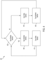
FIG. 4 illustrates aprocess 400 of operating theinput section 300 according to an example. Theprocess 400 may be executed at least in part by thecontrol circuit 224 in some examples. - At
act 402, thecontrol circuit 224 determines whether to open thebackfeed switches 208a-208c. The backfeed switches 208a-208c may be maintained in an open position when power is not being drawn from theinput power connections 202a-202c, and may be maintained in a closed position when power is being drawn from theinput power connections 202a-202c. Power may be drawn from theinput power connections 202a-202c when it is desirable to provide power to the AC/DC converter 210. Power may be provided to the AC/DC converter 210 where it is desirable to provide power to the backuppower source interface 214 and/or to condition input power prior to providing output power to theoutput 206. Power may be provided to the backuppower source interface 214 to provide a recharging current to an energy-storage device coupled to the backuppower source interface 214. Input power may be conditioned (for example, by the AC/DC converter 210 and/or the DC/AC inverter 212) where the input power does not meet output-power requirements for the load. Power may also be provided to the AC/DC converter 210 for other reasons, such as if power is unavailable from other sources. Accordingly, if power is to be provided to the backuppower source interface 214 and/or to theoutput 206 via the DC/AC inverter 212, then thebackfeed switches 208a-208c may be closed. - If the
control circuit 224 determines that thebackfeed switches 208a-208c are not to be opened (402 NO), then theprocess 400 continues to act 404. Otherwise, if thecontrol circuit 224 determines that thebackfeed switches 208a-208c are to be opened (402 YES), then theprocess 400 continues to act 408. - At
act 404, thecontrol circuit 224 opens thesafety switches 220a-220c. Opening thesafety switches 220a-220c may include providing a control signal to thesafety switches 220a-220c to control thesafety switches 220a-220c to open. For example, thesafety switches 220a-220c may include relays, and the control signal may be provided to a control terminal of the relays. Opening thesafety switches 220a-220c decouples the AC/DC converter 210 from thereturn connection 218, thereby galvanically isolating the AC/DC converter 210 from the voltage of thereturn connection 218, which may be a neutral voltage in some examples. - At
act 406, thecontrol circuit 224 closes thebackfeed switches 208a-208c. Closing thebackfeed switches 208a-208c may include providing a control signal to thebackfeed switches 208a-208c to control thebackfeed switches 208a-208c to close. For example, thebackfeed switches 208a-208c may include relays, and the control signal may be provided to a control terminal of the relays. Closing thebackfeed switches 208a-208c couples the AC/DC converter 210 to theinput power connections 202a-202c, thereby allowing input power received from a power source coupled to theinput power connections 202a-202c to be provided to the AC/DC converter 210. In some examples, a time delay (for example, a deadband) is implemented betweenacts safety switches 220a-220c are open before thebackfeed switches 208a-208c are closed to prevent shorting theinput power connections 202a-202c to thereturn connection 218. - The
process 400 then returns to act 402. Acts 402-406 may thereafter be repeated provided that thecontrol circuit 224 again determines that thebackfeed switches 208a-208c are not to be opened. Accordingly, because thesafety switches 220a-220c may already be open and thebackfeed switches 208a-208c may already be closed from previous iterations of acts 402-406, subsequent executions ofacts switches 208a-208c, 220a-220c in their respective states rather than transitioning to those states. Acts 402-406 may be repeated until, for example, thecontrol circuit 224 determines that thebackfeed switches 208a-208c are to be opened (402 YES), at which point theprocess 400 continues to act 408. For example, thecontrol circuit 224 may determine that thebackfeed switches 208a-208c are to be opened because input power is no longer to be drawn from the firstinput power connection 202, such as because acceptable input power is not available from the firstinput power connection 202. - At
act 408, thecontrol circuit 224 opens thebackfeed switches 208a-208c. Opening thebackfeed switches 208a-208c may galvanically isolate the AC/DC converter 210, thereby preventing power from being inadvertently fed back to theinput power connections 202a-202c from the AC/DC converter 210. For example, the hypothetical backfeed power may originate from an energy-storage device coupled to the backuppower source interface 214 and/or from a power source coupled to the secondinput power connection 204. - At
act 410, thecontrol circuit 224 closes thesafety switches 220a-220c. Closing thesafety switches 220a-220c couples the AC/DC converter 210 and the output terminals of thebackfeed switches 208a-208c to thereturn connection 218, which may be maintained at a neutral voltage in some examples. In this example, therefore, the output terminals of thebackfeed switches 208a-208c are maintained at a neutral voltage. A chance of arcing across thebackfeed switches 208a-208c from the output terminals to the input terminals is therefore reduced by maintaining the output terminals at a low (that is, neutral in this example) voltage. In various examples, a time delay (for example, a deadband) is implemented betweenacts backfeed switches 208a-208c are open before thesafety switches 220a-220c are closed to prevent shorting theinput power connections 202a-202c to thereturn connection 218. Theprocess 400 then returns to act 402. - Accordingly, in this example, the
control circuit 224 operates thebackfeed switches 208a-208c in a complementary fashion with thesafety switches 220a-220c. By operating theswitches 208a-208c, 220a-220c in a complementary fashion, the output terminals of thebackfeed switches 208a-208c may be maintained at a neutral voltage while thebackfeed switches 208a-208c are open. Maintaining the output terminals of thebackfeed switches 208a-208c at the neutral voltage reduces a chance of arcing across thebackfeed switches 208a-208c from the output terminals to the input terminals. - The
safety switches 220a-220c provide one example of thesafety switch 220 in which thesafety switch 220 is external to the AC/DC converter 210. In some examples, thesafety switch 220 may be external to the AC/DC converter 210 but may be combined with one or more other components. For example, thesafety switch 220 may be combined with thebackfeed switch 208 in some examples. Whereas theswitches 208a-208c, 220a-220c are illustrated as single-pole, single-throw switches in the example ofFIG. 3 , in other examples theswitches input power connection 202a at one throw, thereturn connection 218 at the other throw, and the AC/DC converter 210 at the single pole. A second SPDT switch may be coupled to the secondinput power connection 202b at one throw, thereturn connection 218 at the other throw, and the AC/DC converter 210 at the single pole. A third SPDT switch may be coupled to the thirdinput power connection 202c at one throw, thereturn connection 218 at the other throw, and the AC/DC converter 210 at the single pole. The SPDT switches may accomplish operation similar to the complementary control of theswitches 208a-208c, 220a-220c inasmuch as the AC/DC converter 210 is coupled, via a respective pole, to either theinput power connections 202a-202c or thereturn connection 218 via one of the two respective throws. - Although the
safety switch 220 is illustrated as being external to the AC/DC converter 210 inFIG. 2 for illustrative clarity, in some examples thesafety switch 220 may be internal to the AC/DC converter 210. For example, thesafety switch 220 may be or include a switching device that is already a component of the AC/DC converter 210. In one example, thesafety switch 220 may also be a power-factor-correction (PFC) boost switch of the AC/DC converter 210. Furthermore, as discussed above, in some examples theinverter switch 222 may be included to offer additional protection against arcing across thebackfeed relay 208. -
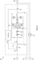
FIG. 5 illustrates a schematic diagram of apower system 500 according to an example. Thepower system 500 may illustrate one example of thepower system 200. In some examples, thepower system 500 illustrates an example of thepower system 200 in which thepower system 200 is a single-phase system. In other examples, thepower system 500 illustrates an example of a portion of thepower system 200 in which thepower system 200 is a multi-phase system, of which thepower system 500 is a single phase. - The
power system 500 includes the firstinput power connection 202, the secondinput power connection 204, theoutput 206, thebackfeed switch 208, the AC/DC converter 210, the DC/AC inverter 212, thebypass switch 216, thecontrol circuit 224, aninput inductor 502, and a DC-bus section 504. Thepower system 500 includes additional components not specifically labeled for purposes of brevity. Furthermore, thepower system 500 may include additional features not illustrated. For example, the DC-bus section 504 may be, or may be coupled to, the backuppower source interface 214 to exchange power with an energy-storage device. The AC/DC converter 210 may include, or be operated as, a power-factor-correction (PFC) circuit. Accordingly, the AC/DC converter 210 may include afirst switch 506, asecond switch 508, and aPFC inductor 510. As discussed below, one or both of theswitches safety switch 220 at one point in time, and one or both of theswitches - The
input inductor 502 is coupled to thebackfeed switch 208 at a first connection, and is coupled to thePFC inductor 510 at a second connection. Thefirst switch 506 is coupled to thePFC inductor 510 at a first connection, and is coupled to thesecond switch 508 at a second connection. Thefirst switch 506 may also be communicatively coupled to thecontrol circuit 224 in some examples. Thesecond switch 508 is coupled to thefirst switch 506 at a first connection, and is coupled to thereturn connection 218 at a second connection. Thesecond switch 508 may also be communicatively coupled to thecontrol circuit 224 in some examples. - The
control circuit 224 is communicatively coupled to thebackfeed switch 208 and theinverter switch 222. In some examples, thecontrol circuit 224 may be communicatively coupled to theswitches control circuit 224 may be coupled to one or more sensors. For example, thecontrol circuit 224 may be coupled to one or more voltage sensors configured to sense a voltage at any of various points in thepower system 500 including, for example, a node between thebackfeed switch 208 and theinput inductor 502, a node between theinput inductor 502 and thePFC inductor 510, or one or more other nodes. - As appreciated by one of skill in the art, when input power is drawn from the first
input power connection 202 via theclosed backfeed switch 208, the AC/DC converter 210 may be operated as a PFC circuit to provide power-factor correction to the input power. The AC/DC converter 210 outputs the power-factor-corrected DC power to the DC-bus section 504, which may store DC power in DC-bus capacitors. As discussed above, the DC-bus section 504 may be coupled to one or more energy-storage devices and may provide at least a portion of the DC power to the energy-storage devices. The DC/AC inverter 212 may draw DC power from the DC-bus section 504, invert the DC power to produce AC power, and provide the AC power to theoutput 206 via theclosed inverter switch 222. In some examples, thecontrol circuit 224 operates the components of the AC/DC converter 210, the DC-bus section 504, and the DC/AC inverter 212 to perform these functions. In other examples, an additional or different controller may perform these functions as discussed below, whereas thecontrol circuit 224 may control only theswitches -
FIG. 6 illustrates aprocess 600 of operating thepower system 500 according to an example. In various examples, theprocess 600 may be executed by thecontrol circuit 224. In some examples, one or more acts of theprocess 600 may be executed by thecontrol circuit 224, and remaining acts of theprocess 600 may be executed by an additional or different controller. For purposes of example, theprocess 600 will be described according to an example in which thecontrol circuit 224 executes theprocess 600. - At
act 602, thecontrol circuit 224 determines whether to open thebackfeed switch 208. Thebackfeed switch 208 may be maintained in an open position when power is not being drawn from the firstinput power connection 202, and may be maintained in a closed position when power is being drawn from the firstinput power connection 202. Power may be drawn from the firstinput power connection 202 when it is desirable to provide power to the AC/DC converter 210. For example, power may be provided to the AC/DC converter 210 where it is desirable to provide power to one or more loads coupled to theoutput 206 and/or one or more energy-storage devices coupled to the DC-bus section 504. Accordingly, if power is to be provided to the AC/DC converter 210, then thebackfeed switch 208 may be closed. - If the
control circuit 224 determines that thebackfeed switch 208 is not to be opened (602 NO), then theprocess 400 continues to act 604. Otherwise, if thecontrol circuit 224 determines that thebackfeed switch 208 is to be opened (602 YES), then theprocess 600 continues to act 608. - At
act 604, thecontrol circuit 224 closes thebackfeed switch 208. Because thecontrol circuit 224 determined that power is to be drawn from the first input power connection 202 (602 NO), thebackfeed switch 208 is closed to enable the AC/DC converter 210 to draw power from the firstinput power connection 202. The AC/DC converter 210 is thus coupled to the firstinput power connection 202 via thebackfeed switch 208 and theinput inductor 502. Thecontrol circuit 224, and/or another control circuit, may then control the AC/DC converter 210 to draw AC power from thefirst input connection 202 via theclosed backfeed switch 208. For example, controlling the AC/DC converter 210 to draw AC power may include operating theswitches - At
act 606, thecontrol circuit 224 operates theswitches input power connection 202. In this state, thepower system 500 operates in a normal mode of operation in which thecomponents input power connection 202, condition the power, and provide output power to one or more loads via theoutput 206. Thepower system 500 may additionally or alternatively provide power (for example, a recharging current) to one or more energy-storage devices coupled to the DC-bus section 504. In some examples, thecomponents control circuit 224. - The
process 600 then returns to act 602. Acts 602-606 may thereafter be repeated provided that thecontrol circuit 224 again determines that thebackfeed switch 208 is not to be opened (602 NO). Accordingly, because thebackfeed switch 208 may already be closed and theswitches switches control circuit 224 determines that thebackfeed switch 208 is to be opened (602 YES), at which point theprocess 600 continues to act 608. For example, thecontrol circuit 224 may determine that thebackfeed switch 208 is to be opened because input power is no longer to be drawn from the firstinput power connection 202, such as because acceptable input power is not available from the firstinput power connection 202. - At
act 608, thecontrol circuit 224 controls thebackfeed switch 208 to be open. Because power is no longer being drawn from the firstinput power connection 202, thebackfeed switch 208 is opened to prevent power from being fed back to a power supply coupled to the firstinput power connection 202. - At
act 610, thecontrol circuit 224 controls theswitches switches switches return connection 218 to the output terminal of thebackfeed switch 208 via theinductors switches safety switch 220 by coupling thebackfeed switch 208 to the return connection 218 (which may, in some examples, be maintained at a neutral voltage) when power is not being drawn from the firstinput power connection 202. Moreover, because no power is being drawn from the firstinput power connection 202, it is not necessary to operate theswitches switches switches backfeed switch 208 is open may advantageously improve backfeed protection without increasing a component count of the AC/DC converter 210 (that is, because theswitches DC converter 210. - At
act 612, thecontrol circuit 224 determines a voltage at an input of the AC/DC converter 210. For example, the voltage may be a voltage at a node between thebackfeed switch 208 and theinput inductor 502, a voltage at a node between theinput inductor 502 and thePFC inductor 510, and/or one or more other nodes. As discussed above, thecontrol circuit 224 may be coupled to one or more voltage sensors which may be configured to sense a voltage at one or more nodes. Because theswitches DC converter 210 may be expected to be at the voltage of thereturn connection 218 which, in various examples, may be a neutral (that is, zero) voltage. - At
act 614, thecontrol circuit 224 determines whether the voltage determined atact 612 exceeds a voltage threshold. For example, the voltage threshold may be approximately 10 V in one example. As discussed above, the voltage determined atact 612 may be expected to be neutral, that is, zero. If the voltage is not at or near zero (for example, by exceeding 10 V) despite theswitches power system 500 may be experiencing a malfunction. For example, one or more diodes in the power system 500 (including, for example, PFC diodes in the AC/DC converter 210) may be malfunctioning and conducting a reverse current giving rise to the abnormally high voltage. If thecontrol circuit 224 determines that the voltage does not exceed the voltage threshold (614 NO), then theprocess 600 returns to act 602. However, if thecontrol circuit 224 determines that the voltage does exceed the voltage threshold (614 YES), then theprocess 600 continues to act 616. - At
act 616, thecontrol circuit 224 opens theinverter switch 222. Opening theinverter switch 222 isolates the AC/DC converter 210, the DC-bus section 504, and the DC/AC inverter 212 from the secondinput power connection 204. Opening theinverter switch 222 may further reduce a chance of backfeeding, such as from the secondinput power connection 204 to the firstinput power connection 202. In examples in which theswitches switches input power connection 204 and the firstinput power connection 202 as compared to only opening one of theswitches switches inverter switch 222 in addition to thebackfeed switch 208 doubles the total air gap between theinput power connections backfeed switch 208. - At
act 618, thecontrol circuit 224 shuts down thepower system 500. Determining that the voltage exceeds the voltage threshold at act 614 (614 YES) may indicate a malfunction in thepower system 500 for which maintenance is desirable or required before continuing to operate thepower system 500. Accordingly, atact 618, thecontrol circuit 224 shuts down thepower system 500 to allow the potential malfunction to be addressed. Shutting down thepower system 500 may include powering off some or all of the components of thepower system 500. In some examples, some functionality, such as user-interface functionality, may remain operational to enable a user to identify and/or diagnose the potential malfunction. - In light of the foregoing, the
safety switch 220 may enhance backfeed protection through any of various implementations. In some examples, thesafety switch 220 includes one or more relay switches coupled between thereturn connection 218 and a node between thebackfeed switch 208 and the AC/DC converter 210. The relay switches may be operated in a complementary fashion with thebackfeed switch 208 to couple the node between thebackfeed switch 208 and the AC/DC converter 210 to a neutral voltage when thebackfeed switch 208 is open. In other examples, thesafety switch 220 includes one or more PFC boost switches in the AC/DC converter 210 and coupled between thereturn connection 218 and the node between thebackfeed switch 208 and the AC/DC converter 210. In this manner, although the PFC boost switches are internal to the AC/DC converter 210, the PFC boost switches may still be considered to be coupled between the input of the AC/DC converter 210 and thereturn connection 218. The PFC boost switches may be operated normally (that is, as PFC boost switches) when thepower system 200 is operating the AC/DC converter 210 in a normal mode of operation (that is, where the AC/DC converter 210 is being controlled to provide power-factor correction to received AC power to yield power-factor-corrected DC power), and may be operated as safety switches (that is, opened complementarily with the backfeed switch 208) otherwise. - In various examples, the
inverter switch 222 may be included to further enhance backfeed protection. Thecontrol circuit 224 may monitor a voltage at the node between thebackfeed switch 208 and the AC/DC converter 210 while thebackfeed switch 208 is open and thesafety switch 220 is closed. If the voltage falls outside of an expected range of voltage values (for example, by being above 10 V in one example), then thecontrol circuit 224 may open theinverter switch 222 to increase an air gap between an output terminal of theinverter switch 222 and an input terminal of thebackfeed switch 208. Although theinverter switch 222 is illustrated in thepower system 500, in other examples of thepower system 500, theinverter switch 222 may be omitted (for example, by being replaced with a short circuit). Furthermore, although the example illustrated in theinput section 300 does not illustrate theinverter switch 222, in various examples theinverter switch 222 may be implemented in a power system including the topology illustrated inFIG. 3 . Although some examples are illustrated as single-phase or multi-phase examples, it is to be appreciated that the principles of the disclosure are applicable to single- and multi-phase implementations. - In some examples, the
control circuit 224 includes one or more controllers. The one or more controllers may execute various operations discussed above. Using data stored in associated memory and/or storage, the one or more controllers may also execute one or more instructions stored on one or more non-transitory computer-readable media, which the one or more controllers may include and/or be coupled to, that may result in manipulated data. In some examples, the one or more controllers may include one or more processors or other types of controllers. In one example, the one or more controllers are or include at least one processor. In another example, the one or more controllers perform at least a portion of the operations discussed above using an application-specific integrated circuit tailored to perform particular operations in addition to, or in lieu of, a general-purpose processor. As illustrated by these examples, examples in accordance with the present disclosure may perform the operations described herein using many specific combinations of hardware and software and the disclosure is not limited to any particular combination of hardware and software components. Examples of the disclosure may include a computer-program product configured to execute methods, processes, and/or operations discussed above. The computer-program product may be, or include, one or more controllers and/or processors configured to execute instructions to perform methods, processes, and/or operations discussed above. - In some examples, the
control circuit 224 may include hardware logic components in addition to, or in lieu of, software components (for example, one or more controllers configured to execute stored instructions). For example, to control theinverter switch 222, thecontrol circuit 224 may include at least one comparator configured to determine whether a voltage at the node between thebackfeed switch 208 and the AC/DC converter 210 exceeds a threshold voltage. Sensing circuitry, such as one or more voltage sensors, may send a sense signal indicative of a voltage at the node to the at least one comparator. The at least one comparator may open theinverter switch 222 if the voltage exceeds the threshold voltage, or may provide a signal indicative of the overvoltage to one or more controllers. The one or more controllers may initiate the shutdown operations discussed above. In some examples, the threshold voltage may be 10 V. In other examples, the threshold voltage may be another value. - Further examples are provided in the following clauses.
-
Clause 1. A power system comprising: - an input power connection;
- a return connection;
- a power converter having a converter input;
- a backfeed switch coupled between the input power connection and the converter input;
- at least one safety switch coupled between the converter input and the return connection; and
-
Clause 2. The power system ofclause 1, wherein the at least one safety switch includes a relay having a first connection coupled between the converter input and the backfeed switch, and a second connection coupled to the return connection. - Clause 3. The power system of
clause 1, wherein the at least one safety switch includes at least one power-factor-correction (PFC) boost switch configured to provide power-factor correction to input power received at the input power connection. -
Clause 4. The power system ofclause 1, wherein closing the at least one safety switch couples the converter input to neutral. - Clause 5. The power system of
clause 1, further comprising: - an inverter coupled to the power converter;
- an output connection; and
- at least one inverter switch coupled between the inverter and the output connection.
- Clause 6. The power system of clause 5, wherein the at least one control circuit is further configured to:
- determine, while the at least one safety switch is closed, a voltage at the converter input; and
- open the at least one inverter switch responsive to determining that the voltage exceeds a voltage threshold.
- Clause 7. The power system of clause 5, further comprising:
- a second input power connection; and
- a bypass switch having a first connection coupled to the second input power connection and a second connection coupled between the at least one inverter switch and the output connection.
- Clause 8. The power system of
clause 1, wherein the at least one safety switch is configured to open when the backfeed switch closes. - Clause 9. The power system of
clause 1, wherein the at least one control circuit is further configured to: - determine, while the at least one safety switch is closed, a voltage at the converter input; and
- shut down the power system responsive to determining that the voltage exceeds a voltage threshold.
-
Clause 10. A method of operating a power system having an input power connection, a return connection, a power converter having a converter input, a backfeed switch coupled between the input power connection and the converter input, and at least one safety switch coupled between the converter input and the return connection, the method comprising: - opening the backfeed switch to disconnect the converter input from the input power connection; and
- closing the at least one safety switch responsive to opening the backfeed switch to connect the converter input to the return connection.
- Clause 11. The method of
clause 10, wherein the at least one safety switch includes at least one power-factor-correction (PFC) boost switch and the method further comprises providing, by the PFC boost switch, power-factor correction to input power received at the input power connection. - Clause 12. The method of clause 11, wherein closing the at least one safety switch couples the converter input to neutral.
- Clause 13. The method of
clause 10, wherein the power system includes an inverter coupled to the power converter, an output connection, and at least one inverter switch coupled between the inverter and the output connection, the method further comprising: - determining, while the at least one safety switch is closed, a voltage at the converter input; and
- opening the at least one inverter switch responsive to determining that the voltage exceeds a voltage threshold.
- Clause 14. The method of
clause 10, further comprising opening the at least one safety switch when the backfeed switch closes. -
Clause 15. A non-transitory computer-readable medium storing thereon sequences of computer-executable instructions for operating a power system having an input power connection, a return connection, a power converter having a converter input, a backfeed switch coupled between the input power connection and the converter input, and at least one safety switch coupled between the converter input and the return connection, the sequences of computer-executable instructions including instructions that instruct at least one processor to operate according to any of the above method clause 10-14. - Having thus described several aspects of at least one embodiment, it is to be appreciated various alterations, modifications, and improvements will readily occur to those skilled in the art. Such alterations, modifications, and improvements are intended to be part of, and within the scope of, this disclosure. Accordingly, the foregoing description and drawings are by way of example only.
Claims (15)
- A power system comprising:an input power connection;a return connection;a power converter having a converter input;a backfeed switch coupled between the input power connection and the converter input;at least one safety switch coupled between the converter input and the return connection; andat least one control circuit configured to control the at least one safety switch to be closed when the backfeed switch opens.
- The power system of claim 1, wherein the at least one safety switch includes either or both of:a relay having a first connection coupled between the converter input and the backfeed switch, and a second connection coupled to the return connection; andat least one power-factor-correction (PFC) boost switch configured to provide power-factor correction to input power received at the input power connection.
- The power system of claims 1 or 2, wherein closing the at least one safety switch couples the converter input to neutral.
- The power system of any of the above claims, further comprising:an inverter coupled to the power converter;an output connection; andat least one inverter switch coupled between the inverter and the output connection.
- The power system of claim 4, wherein the at least one control circuit is further configured to:determine, while the at least one safety switch is closed, a voltage at the converter input; andopen the at least one inverter switch responsive to determining that the voltage exceeds a voltage threshold.
- The power system of claim 4, further comprising:a second input power connection; anda bypass switch having a first connection coupled to the second input power connection and a second connection coupled between the at least one inverter switch and the output connection.
- The power system of any of the above claims, wherein the at least one safety switch is configured to open when the backfeed switch closes.
- The power system of any of the above claims, wherein the at least one control circuit is further configured to:determine, while the at least one safety switch is closed, a voltage at the converter input; andshut down the power system responsive to determining that the voltage exceeds a voltage threshold.
- A method of operating a power system having an input power connection, a return connection, a power converter having a converter input, a backfeed switch coupled between the input power connection and the converter input, and at least one safety switch coupled between the converter input and the return connection, the method comprising:opening the backfeed switch to disconnect the converter input from the input power connection; andclosing the at least one safety switch responsive to opening the backfeed switch to connect the converter input to the return connection.
- The method of claim 9, wherein the at least one safety switch includes at least one power-factor-correction (PFC) boost switch and the method further comprises providing, by the PFC boost switch, power-factor correction to input power received at the input power connection.
- The method of claim 10, wherein closing the at least one safety switch couples the converter input to neutral.
- The method of any of the claims 9 to 11, wherein the power system includes an inverter coupled to the power converter, an output connection, and at least one inverter switch coupled between the inverter and the output connection, the method further comprising:determining, while the at least one safety switch is closed, a voltage at the converter input; andopening the at least one inverter switch responsive to determining that the voltage exceeds a voltage threshold.
- The method of any of the claims 9 to 12, further comprising opening the at least one safety switch when the backfeed switch closes.
- A non-transitory computer-readable medium storing thereon sequences of computer-executable instructions for operating a power system having an input power connection, a return connection, a power converter having a converter input, a backfeed switch coupled between the input power connection and the converter input, and at least one safety switch coupled between the converter input and the return connection, the sequences of computer-executable instructions including instructions that instruct at least one processor to operate according to any of the above method claims 9 to 13.
- A computer program comprising instructions to cause the device of any of the claims 1 to 8 to carry out the method of any of claims 9 to 13.
Applications Claiming Priority (1)
| Application Number | Priority Date | Filing Date | Title |
|---|---|---|---|
| US18/147,797 US12620830B2 (en) | 2022-12-29 | Backfeed protection circuit |
Publications (2)
| Publication Number | Publication Date |
|---|---|
| EP4395121A2 true EP4395121A2 (en) | 2024-07-03 |
| EP4395121A3 EP4395121A3 (en) | 2024-07-31 |
Family
ID=89223347
Family Applications (1)
| Application Number | Title | Priority Date | Filing Date |
|---|---|---|---|
| EP23217244.5A Pending EP4395121A3 (en) | 2022-12-29 | 2023-12-15 | Power system and method of operating a power system |
Country Status (1)
| Country | Link |
|---|---|
| EP (1) | EP4395121A3 (en) |
Family Cites Families (3)
| Publication number | Priority date | Publication date | Assignee | Title |
|---|---|---|---|---|
| US7821749B2 (en) * | 2007-03-30 | 2010-10-26 | General Electric Company | Arc flash elimination apparatus and method |
| US11488792B2 (en) * | 2017-08-07 | 2022-11-01 | Nec Corporation | Grounding circuit, electrical apparatus, grounding control method, and grounding control program |
| EP3806281B1 (en) * | 2019-10-11 | 2023-07-26 | Schneider Electric IT Corporation | Method for reducing ups component stresses during transition from inverter to green/bypass operation |
-
2023
- 2023-12-15 EP EP23217244.5A patent/EP4395121A3/en active Pending
Also Published As
| Publication number | Publication date |
|---|---|
| EP4395121A3 (en) | 2024-07-31 |
| US20240223003A1 (en) | 2024-07-04 |
Similar Documents
| Publication | Publication Date | Title |
|---|---|---|
| EP1723712B1 (en) | Multi-mode uninterruptible power supplies and methods of operation thereof | |
| EP3185393B1 (en) | Ups with integrated bypass switch | |
| AU3004899A (en) | Systems and methods for producing standby uninterruptible power for ac loads using rectified ac and battery | |
| EP3840204A2 (en) | Dc-dc power converter with four way power conversion | |
| US12334775B2 (en) | Power supply system and control method | |
| US12261479B2 (en) | Arrangement of converters and fast switches to provide BESS and UPS combined function | |
| EP4395121A2 (en) | Power system and method of operating a power system | |
| US12620830B2 (en) | Backfeed protection circuit | |
| US11955833B2 (en) | Intelligent load control to support peak load demands in electrical circuits | |
| EP4030585A1 (en) | Intelligent load control to support peak load demands in electrical circuits | |
| US20230179013A1 (en) | Uninterruptible Power Supply, On-Off Control Module, Control Method, and System | |
| EP4329146A1 (en) | Automatic power source transfer apparatus | |
| US11621580B2 (en) | Microgrid switchover using zero-cross detection | |
| JPH0429532A (en) | Battery switching circuit | |
| KR102956477B1 (en) | Microgrid switchover using zero-cross detection | |
| CN216056460U (en) | Power supply system | |
| CN216489897U (en) | UPS with rectifier serving as inverter and active filter | |
| CA3226297C (en) | Microgrid switchover using zero-cross detection | |
| US11824466B2 (en) | Instantaneous line swell protection for UPS | |
| CN213213177U (en) | Off-line uninterrupted power supply | |
| CN210074862U (en) | On-line interactive uninterrupted power supply | |
| JP2003070184A (en) | Uninterruptible power supply system | |
| JP3037646U (en) | Uninterruptible power system | |
| CN117375196A (en) | Solid state automatic transfer switch and method of operating the same | |
| JPH06165411A (en) | Uninterruptible power supply |
Legal Events
| Date | Code | Title | Description |
|---|---|---|---|
| PUAI | Public reference made under article 153(3) epc to a published international application that has entered the european phase |
Free format text: ORIGINAL CODE: 0009012 |
|
| STAA | Information on the status of an ep patent application or granted ep patent |
Free format text: STATUS: THE APPLICATION HAS BEEN PUBLISHED |
|
| PUAL | Search report despatched |
Free format text: ORIGINAL CODE: 0009013 |
|
| AK | Designated contracting states |
Kind code of ref document: A2 Designated state(s): AL AT BE BG CH CY CZ DE DK EE ES FI FR GB GR HR HU IE IS IT LI LT LU LV MC ME MK MT NL NO PL PT RO RS SE SI SK SM TR |
|
| AK | Designated contracting states |
Kind code of ref document: A3 Designated state(s): AL AT BE BG CH CY CZ DE DK EE ES FI FR GB GR HR HU IE IS IT LI LT LU LV MC ME MK MT NL NO PL PT RO RS SE SI SK SM TR |
|
| RIC1 | Information provided on ipc code assigned before grant |
Ipc: H01H 9/30 20060101ALI20240626BHEP Ipc: H02J 9/06 20060101AFI20240626BHEP |
|
| STAA | Information on the status of an ep patent application or granted ep patent |
Free format text: STATUS: REQUEST FOR EXAMINATION WAS MADE |
|
| 17P | Request for examination filed |
Effective date: 20250107 |