EP4395108A1 - Battery pack system and energy storage system - Google Patents
Battery pack system and energy storage system Download PDFInfo
- Publication number
- EP4395108A1 EP4395108A1 EP22860988.9A EP22860988A EP4395108A1 EP 4395108 A1 EP4395108 A1 EP 4395108A1 EP 22860988 A EP22860988 A EP 22860988A EP 4395108 A1 EP4395108 A1 EP 4395108A1
- Authority
- EP
- European Patent Office
- Prior art keywords
- battery
- current
- basic
- pack system
- battery pack
- Prior art date
- Legal status (The legal status is an assumption and is not a legal conclusion. Google has not performed a legal analysis and makes no representation as to the accuracy of the status listed.)
- Pending
Links
Images




Classifications
-
- H—ELECTRICITY
- H02—GENERATION; CONVERSION OR DISTRIBUTION OF ELECTRIC POWER
- H02H—EMERGENCY PROTECTIVE CIRCUIT ARRANGEMENTS
- H02H7/00—Emergency protective circuit arrangements specially adapted for specific types of electric machines or apparatus or for sectionalised protection of cable or line systems, and effecting automatic switching in the event of an undesired change from normal working conditions
- H02H7/18—Emergency protective circuit arrangements specially adapted for specific types of electric machines or apparatus or for sectionalised protection of cable or line systems, and effecting automatic switching in the event of an undesired change from normal working conditions for batteries; for accumulators
-
- H—ELECTRICITY
- H01—ELECTRIC ELEMENTS
- H01M—PROCESSES OR MEANS, e.g. BATTERIES, FOR THE DIRECT CONVERSION OF CHEMICAL ENERGY INTO ELECTRICAL ENERGY
- H01M10/00—Secondary cells; Manufacture thereof
- H01M10/42—Methods or arrangements for servicing or maintenance of secondary cells or secondary half-cells
- H01M10/48—Accumulators combined with arrangements for measuring, testing or indicating the condition of cells, e.g. the level or density of the electrolyte
-
- H—ELECTRICITY
- H01—ELECTRIC ELEMENTS
- H01M—PROCESSES OR MEANS, e.g. BATTERIES, FOR THE DIRECT CONVERSION OF CHEMICAL ENERGY INTO ELECTRICAL ENERGY
- H01M50/00—Constructional details or processes of manufacture of the non-active parts of electrochemical cells other than fuel cells, e.g. hybrid cells
- H01M50/50—Current conducting connections for cells or batteries
- H01M50/502—Interconnectors for connecting terminals of adjacent batteries; Interconnectors for connecting cells outside a battery casing
- H01M50/509—Interconnectors for connecting terminals of adjacent batteries; Interconnectors for connecting cells outside a battery casing characterised by the type of connection, e.g. mixed connections
- H01M50/51—Connection only in series
-
- H—ELECTRICITY
- H01—ELECTRIC ELEMENTS
- H01M—PROCESSES OR MEANS, e.g. BATTERIES, FOR THE DIRECT CONVERSION OF CHEMICAL ENERGY INTO ELECTRICAL ENERGY
- H01M50/00—Constructional details or processes of manufacture of the non-active parts of electrochemical cells other than fuel cells, e.g. hybrid cells
- H01M50/50—Current conducting connections for cells or batteries
- H01M50/502—Interconnectors for connecting terminals of adjacent batteries; Interconnectors for connecting cells outside a battery casing
- H01M50/509—Interconnectors for connecting terminals of adjacent batteries; Interconnectors for connecting cells outside a battery casing characterised by the type of connection, e.g. mixed connections
- H01M50/512—Connection only in parallel
-
- H—ELECTRICITY
- H02—GENERATION; CONVERSION OR DISTRIBUTION OF ELECTRIC POWER
- H02J—ELECTRIC POWER NETWORKS; CIRCUIT ARRANGEMENTS OR SYSTEMS FOR SUPPLYING OR DISTRIBUTING ELECTRIC POWER; SYSTEMS FOR STORING ELECTRIC ENERGY
- H02J3/00—Circuit arrangements for AC mains or AC distribution networks
- H02J3/28—Arrangements for balancing of the load in networks by storage of energy
- H02J3/32—Arrangements for balancing of the load in networks by storage of energy using batteries or super capacitors with converting means
-
- H—ELECTRICITY
- H02—GENERATION; CONVERSION OR DISTRIBUTION OF ELECTRIC POWER
- H02J—ELECTRIC POWER NETWORKS; CIRCUIT ARRANGEMENTS OR SYSTEMS FOR SUPPLYING OR DISTRIBUTING ELECTRIC POWER; SYSTEMS FOR STORING ELECTRIC ENERGY
- H02J7/00—Circuit arrangements for charging or discharging batteries or for supplying loads from batteries
- H02J7/50—Circuit arrangements for charging or discharging batteries or for supplying loads from batteries acting upon multiple batteries simultaneously or sequentially
-
- H—ELECTRICITY
- H02—GENERATION; CONVERSION OR DISTRIBUTION OF ELECTRIC POWER
- H02J—ELECTRIC POWER NETWORKS; CIRCUIT ARRANGEMENTS OR SYSTEMS FOR SUPPLYING OR DISTRIBUTING ELECTRIC POWER; SYSTEMS FOR STORING ELECTRIC ENERGY
- H02J7/00—Circuit arrangements for charging or discharging batteries or for supplying loads from batteries
- H02J7/60—Circuit arrangements for charging or discharging batteries or for supplying loads from batteries including safety or protection arrangements
- H02J7/64—Circuit arrangements for charging or discharging batteries or for supplying loads from batteries including safety or protection arrangements against overvoltage
-
- H—ELECTRICITY
- H01—ELECTRIC ELEMENTS
- H01M—PROCESSES OR MEANS, e.g. BATTERIES, FOR THE DIRECT CONVERSION OF CHEMICAL ENERGY INTO ELECTRICAL ENERGY
- H01M10/00—Secondary cells; Manufacture thereof
- H01M10/42—Methods or arrangements for servicing or maintenance of secondary cells or secondary half-cells
- H01M10/425—Structural combination with electronic components, e.g. electronic circuits integrated to the outside of the casing
- H01M2010/4271—Battery management systems including electronic circuits, e.g. control of current or voltage to keep battery in healthy state, cell balancing
-
- H—ELECTRICITY
- H01—ELECTRIC ELEMENTS
- H01M—PROCESSES OR MEANS, e.g. BATTERIES, FOR THE DIRECT CONVERSION OF CHEMICAL ENERGY INTO ELECTRICAL ENERGY
- H01M10/00—Secondary cells; Manufacture thereof
- H01M10/42—Methods or arrangements for servicing or maintenance of secondary cells or secondary half-cells
- H01M10/425—Structural combination with electronic components, e.g. electronic circuits integrated to the outside of the casing
- H01M2010/4278—Systems for data transfer from batteries, e.g. transfer of battery parameters to a controller, data transferred between battery controller and main controller
-
- H—ELECTRICITY
- H02—GENERATION; CONVERSION OR DISTRIBUTION OF ELECTRIC POWER
- H02J—ELECTRIC POWER NETWORKS; CIRCUIT ARRANGEMENTS OR SYSTEMS FOR SUPPLYING OR DISTRIBUTING ELECTRIC POWER; SYSTEMS FOR STORING ELECTRIC ENERGY
- H02J7/00—Circuit arrangements for charging or discharging batteries or for supplying loads from batteries
- H02J7/02—Circuit arrangements for charging or discharging batteries or for supplying loads from batteries for charging batteries from AC mains by converters
- H02J7/04—Regulation of charging current or voltage
- H02J7/06—Regulation of charging current or voltage using discharge tubes or semiconductor devices
-
- Y—GENERAL TAGGING OF NEW TECHNOLOGICAL DEVELOPMENTS; GENERAL TAGGING OF CROSS-SECTIONAL TECHNOLOGIES SPANNING OVER SEVERAL SECTIONS OF THE IPC; TECHNICAL SUBJECTS COVERED BY FORMER USPC CROSS-REFERENCE ART COLLECTIONS [XRACs] AND DIGESTS
- Y02—TECHNOLOGIES OR APPLICATIONS FOR MITIGATION OR ADAPTATION AGAINST CLIMATE CHANGE
- Y02E—REDUCTION OF GREENHOUSE GAS [GHG] EMISSIONS, RELATED TO ENERGY GENERATION, TRANSMISSION OR DISTRIBUTION
- Y02E60/00—Enabling technologies; Technologies with a potential or indirect contribution to GHG emissions mitigation
- Y02E60/10—Energy storage using batteries
Definitions
- the present invention relates to a battery pack system and an energy storage system.
- An energy storage system connected to a power system and a battery pack system constituting the energy storage system should be safe systems so as not to develop into a fire even if an abnormality has occurred.
- battery cells constituting the battery pack system are provided with a current cutoff mechanism that stops a current flowing through the battery cells at the time of abnormality. At the time of abnormality of the battery cell, the current flowing through the battery cell can be cut off by the current cutoff mechanism, but in a battery pack system in which a plurality of battery cells are connected in series and in parallel, there is a possibility that a high voltage is applied to the battery cell in which the current is cut off.
- the plurality of battery cells 41 connected in series are referred to as a module 42.
- a plurality of modules 42 connected in series are referred to as a rack 43.
- a plurality of racks 43 connected in parallel are referred to as an assembly 44.
- a plurality of assemblies 44 connected in series are referred to as a stack 45.
- a plurality of stacks 45 connected in parallel are referred to as a storage 46.
- the storage 46 is the battery pack system 10.
- the voltage of the battery pack system 10 is determined by the number of the battery cells 41 connected in series.
- the capacity of the battery pack system 10 is determined by the number of the battery cells 41 connected in parallel.
- the battery pack system 10 includes a capacitor 80 connected in parallel with the basic battery unit 60.
- a surge voltage is generated by the inductance component 81 of the wiring.
- the battery pack system 10 includes the capacitor 80 as an absorption means that absorbs the surge voltage.
- the capacitor 80 may be a varistor, a Zener diode, or a combination thereof.
- the module 42 described above can be replaced with the assembly 44.
- the basic battery unit 60 in FIG. 10(b) corresponds to the stack 45. Note that details of FIG. 10(b) are similar to those of FIG. 10(a) , and thus description thereof is omitted.
Landscapes
- Engineering & Computer Science (AREA)
- Power Engineering (AREA)
- Chemical & Material Sciences (AREA)
- Chemical Kinetics & Catalysis (AREA)
- Electrochemistry (AREA)
- General Chemical & Material Sciences (AREA)
- Manufacturing & Machinery (AREA)
- Charge And Discharge Circuits For Batteries Or The Like (AREA)
- Protection Of Static Devices (AREA)
- Remote Monitoring And Control Of Power-Distribution Networks (AREA)
- Connection Of Batteries Or Terminals (AREA)
Abstract
Description
- The present invention relates to a battery pack system and an energy storage system.
- An energy storage system connected to a power system and a battery pack system constituting the energy storage system should be safe systems so as not to develop into a fire even if an abnormality has occurred. In general, battery cells constituting the battery pack system are provided with a current cutoff mechanism that stops a current flowing through the battery cells at the time of abnormality. At the time of abnormality of the battery cell, the current flowing through the battery cell can be cut off by the current cutoff mechanism, but in a battery pack system in which a plurality of battery cells are connected in series and in parallel, there is a possibility that a high voltage is applied to the battery cell in which the current is cut off.
- PTL 1 discloses a technique in which input sides of a plurality of DC/DC converters are connected in series, and an output side of each of the plurality of DC/DC converters is connected to a battery pack system, so that a voltage applied to each battery pack system is reduced to prevent a high voltage from being applied to a battery cell.
- PTL 1:
WO 2020/007464 A - However, in PTL 1, since the DC/DC converter is required for the battery pack system, the number of components increases. In addition, efficiency decreases due to switching loss of the DC/DC converter.
- Therefore, the present invention provides a technique for suppressing application of a high voltage to a battery cell in which a current is cut off without using a DC/DC converter.
- A battery pack system of the present invention is a battery pack system including a plurality of basic battery units in which a plurality of battery cells charged by a current supplied from a power supply are connected in series, and one or a plurality of battery groups in which the plurality of basic battery units are connected in parallel. Each of the plurality of battery cells includes a current cutoff means that cuts off a current flowing between electrodes of the battery cells, and a series number of the plurality of battery cells connected in series in the basic battery unit is determined based on a parallel number of the basic battery units, a current supplied from the power supply, and a resistance component of the battery cell.
- According to the present invention, it is possible to suppress application of a high voltage to a battery cell in which a current is cut off without using a DC/DC converter.
-
- [
FIG. 1] FIG. 1 is a block diagram illustrating an energy storage system of a first embodiment. - [
FIG. 2] FIG. 2 is a diagram illustrating an AC/DC converter of the first embodiment. - [
FIG. 3] FIG. 3 is a hardware block diagram of a control unit of the first embodiment. - [
FIG. 4] FIG. 4 is a diagram illustrating a battery pack system of the first embodiment. - [
FIG. 5] FIG. 5 is a diagram illustrating a current cutoff mechanism of a battery cell of the first embodiment. - [
FIG. 6] FIG. 6 is a diagram illustrating connection of conventional battery cells and a diagram illustrating connection of battery cells of the first embodiment. - [
FIG. 7] FIG. 7 is a diagram illustrating a voltage applied to a battery cell in which a current is cut off. - [
FIG. 8] FIG. 8 is a diagram illustrating capacitors that absorb a surge voltage in the first embodiment. - [
FIG. 9] FIG. 9 is a diagram for describing effects of the first embodiment. - [
FIG. 10] FIG. 10 is a diagram illustrating a battery pack system of a second embodiment. - Embodiments of the present invention will be described in detail with reference to the drawings. In the following embodiments, it goes without saying that the components (including element steps and the like) are not necessarily essential unless otherwise specified or considered to be obviously essential in principle.
- An energy storage system 1 of a first embodiment supplies active power and reactive power to an
AC system 11. In addition, the energy storage system 1 may be connected to high-load industrial equipment or the like to improve power quality of the industrial equipment or the like. As illustrated inFIG. 1 , the energy storage system 1 includes atransformer 12, afilter 13, an AC/DC converter 14, and abattery pack system 10. Thetransformer 12 is connected to theAC system 11 and transmits energy between a plurality of windings using electromagnetic induction. Thefilter 13 removes a predetermined frequency component. - The AC/
DC converter 14 is electrically connected to theAC system 11 via thetransformer 12 and thefilter 13. The AC/DC converter 14 is a two-level converter, a three-level converter, or a multi-level converter. When the AC/DC converter 14 is a two-level converter, the AC/DC converter 14 can be configured with a small number of components. When the AC/DC converter 14 is a three-level converter, thefilter 13 can be configured to be small. When the AC/DC converter 14 is a multi-level converter, thefilter 13 can be omitted. - The AC/
DC converter 14 is a power supply that supplies a current to thebattery pack system 10.FIG. 2 illustrates the AC/DC converter 14 including a two-level converter. As illustrated inFIG. 2 , the AC/DC converter 14 is a circuit that converts three-phase alternating currents having phases different from each other by 120° into direct currents. An AC-side terminal 24 of the AC/DC converter 14 is connected to thefilter 13, and a DC-side terminal 25 is connected to thebattery pack system 10. The AC/DC converter 14 includes abridge circuit 20 that converts an alternating current into a direct current, asmoothing capacitor 23, and acontrol unit 15. Thebridge circuit 20 includes six parallel circuits each including aswitching element 21 and adiode 22. Eachswitching element 21 is controlled to be turned on or off by thecontrol unit 15. - The
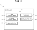
control unit 15 adjusts the gate pulse signal output by predetermined control to control on or off of theswitching element 21 of the AC/DC converter 14. The predetermined control is, for example, constant voltage control, constant current control, or constant power control. Thecontrol unit 15 is communicably connected to a battery management system (BMS) 16. Then, the BMS 16 is communicably connected to thebattery pack system 10, and collects the state of thebattery pack system 10. The state of thebattery pack system 10 is, for example, the voltage of abattery cell 41, the temperature of thebattery cell 41, the life of thebattery cell 41, and the like. In addition, the BMS 16 stores the state of thebattery pack system 10 and manages the operation, performance, life, and the like of thebattery pack system 10. The BMS 16 transmits a signal based on the collected information of thebattery pack system 10 to the AC/DC converter 14. For example, when an abnormality has occurred in thebattery cell 41 or when an abnormality is suspected, theBMS 16 transmits a signal indicating the abnormality to thecontrol unit 15. Then, thecontrol unit 15 controls on or off of theswitching element 21 according to the signal indicating the abnormality output from theBMS 16, and reduces or stops the current output to thebattery pack system 10. As illustrated inFIG. 3 , thecontrol unit 15 includes aprocessor 301, a communication interface (hereinafter, abbreviated as an I/F) 302, amain storage device 303, anauxiliary storage device 304, an input/output I/F 305, and abus 306 that communicably connects the units described above. - The
processor 301 is a central processing unit that controls the operation of each unit of thecontrol unit 15. Theprocessor 301 is, for example, a central processing unit (CPU), a digital signal processor (DSP), an application specific integrated circuit (ASIC), or the like. Theprocessor 301 develops the program stored in theauxiliary storage device 304 in a work area of themain storage device 303 in an executable manner. Themain storage device 303 stores a program executed by theprocessor 301, data processed by the processor, and the like. Themain storage device 303 is a flash memory, a random access memory (RAM), a read only memory (ROM), or the like. Theauxiliary storage device 304 stores various programs and various data. Theauxiliary storage device 304 stores, for example, an operating system (OS), various programs, various tables, and the like. Theauxiliary storage device 304 is a silicon disk including a nonvolatile semiconductor memory (flash memory, EPROM (erasable programmable ROM)), a solid state drive device, a hard disk (HDD, hard disk drive) device, or the like. - The communication I/
F 302 functions as a means that transmits and receives data to and from theBMS 16 which is an external device. The input/output I/F 305 receives an operation instruction or the like from a user who operates an input device connected to the input/output I/F 305. The input device is, for example, a keyboard, a touch panel, a mouse, a microphone, or the like. Furthermore, for example, a display device such as an LCD, an electroluminescence (EL) panel, or an organic EL panel, or an output device such as a printer or a speaker can be connected to the input/output I/F 305. The input/output I/F 305 outputs data and information processed by theprocessor 301 and data and information stored in themain storage device 303 and theauxiliary storage device 304 to an output device (for example, a display unit or a printing device (not illustrated)). - The
battery pack system 10 is a system in whichbattery cells 41 as minimum units are connected in series and in parallel, and thesebattery cells 41 are charged by a voltage output from the AC/DC converter 14. In order to use thebattery pack system 10 in a power transmission system, thebattery pack system 10 needs to have, for example, a charge/discharge capacity of 40 kV. In this case, when the charge/discharge capacity of thebattery cell 41 is 4 V, it is necessary to connect 10,000battery cells 41 in series. Thebattery cell 41 is, for example, a lithium ion battery or a lead storage battery. Thebattery pack system 10 is electrically connected to the DC-side terminal 25 of the AC/DC converter 14. Thebattery pack system 10 is charged by being applied with the DC voltage output from the AC/DC converter 14. The chargedbattery pack system 10 is discharged to theAC system 11 via the AC/DC converter 14. - Details of the
battery pack system 10 will be described with reference toFIG. 4 . The plurality ofbattery cells 41 connected in series are referred to as amodule 42. A plurality ofmodules 42 connected in series are referred to as arack 43. A plurality ofracks 43 connected in parallel are referred to as anassembly 44. A plurality ofassemblies 44 connected in series are referred to as astack 45. A plurality ofstacks 45 connected in parallel are referred to as astorage 46. Thestorage 46 is thebattery pack system 10. The voltage of thebattery pack system 10 is determined by the number of thebattery cells 41 connected in series. In addition, the capacity of thebattery pack system 10 is determined by the number of thebattery cells 41 connected in parallel. - A
circuit breaker 47 that cuts off an electric current is provided between theassembly 44 and theassembly 44. Thecircuit breaker 47 may be provided between themodule 42 and themodule 42, or may be provided between thebattery cell 41 and thebattery cell 41. Thecircuit breaker 47 may be hardware that cuts off a current when an overcurrent occurs, or may be a switch that cuts off a current by software control by thecontrol unit 15 or the like. - As illustrated in
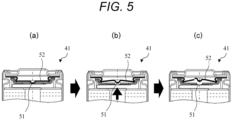
FIG. 5 , thebattery cell 41 includes acurrent cutoff mechanism 51 and asafety valve 52. Thecurrent cutoff mechanism 51 functions as a current cutoff means of the present invention that cuts off the current flowing between the electrodes. When placed in an overcurrent or high-temperature state, thecurrent cutoff mechanism 51 is deformed by an increase in pressure inside thebattery cell 41 to be electrically opened, and cuts off the current flowing between the electrodes of thebattery cell 41. In addition, thesafety valve 52 ruptures when the internal pressure of thebattery cell 41 increases, and releases the gas generated inside thebattery cell 41. Thebattery cell 41 of the first embodiment includes both thecurrent cutoff mechanism 51 and thesafety valve 52, but thebattery cell 41 may include any one of thecurrent cutoff mechanism 51 and thesafety valve 52. In addition, thebattery cell 41 may have a configuration other than thecurrent cutoff mechanism 51 as long as the current can be cut off when thebattery cell 41 is abnormal. In addition, thecurrent cutoff mechanism 51 may be electrically opened inside the cell when thebattery cell 41 is abnormal, or may be a separator that is dissolved to become an insulating material when thebattery cell 41 is abnormal. The separator is, for example, a permeable membrane through which Li ions pass, and is dissolved to become an insulating material when thebattery cell 41 is abnormal. Also in this case, an electrically high state is established, which can be regarded as electrically open. - (a) of
FIG. 6 illustrates connection ofbattery cells 41 of a conventionalbattery pack system 100, and (b) ofFIG. 6 illustrates connection of thebattery cells 41 of thebattery pack system 10 of the first embodiment. In the conventionalbattery pack system 100, a plurality ofbattery cells 41 are connected in series, and a plurality ofbasic battery units 60 having a plurality ofbattery cells 41 connected in series are provided, and the plurality ofbasic battery units 60 are connected in parallel. When there is no abnormality in thebattery cell 41, a current It supplied from the AC/DC converter 14 to thebattery pack system 100 is divided into the plurality ofbasic battery units 60 connected in parallel, and the current I is supplied to eachbasic battery unit 60. Thebasic battery unit 60 of the first embodiment corresponds to themodule 42. - In the conventional
battery pack system 100 of (a) ofFIG. 6 , the series number of thebattery cells 41 in thebasic battery unit 60 is Ns, and the parallel number of thebasic battery units 60 is Np. When the current supplied from the AC/DC converter 14 is It, and the current distributed to eachbasic battery unit 60 is I, It = Np × I is obtained. When a resistance component of eachbattery cell 41 is R and a battery voltage of thebattery cell 41 is E, a voltage across onebattery cell 41 is a sum of a voltage drop in the resistance component and the battery voltage (= I × R + E). Since the series number of thebattery cells 41 in thebasic battery unit 60 is Ns, the voltage V0 of thebasic battery unit 60 is V0 = Ns × (I × R + E). - When an abnormality has occurred in a
certain battery cell 41 and thecurrent cutoff mechanism 51 or thesafety valve 52 operates, the current flowing through thebattery cell 41 and thebasic battery unit 60 including thebattery cell 41 is cut off. On the other hand, when the AC/DC converter 14 operates under constant current control, the current It supplied from the AC/DC converter 14 is constant. Therefore, when the current flowing through thebasic battery unit 60 in which no abnormality has occurred is I', I' = It/(Np - 1) is satisfied. - In the voltage V2 of the
basic battery unit 60 in which no abnormality has occurred, since the flowing current I' is larger than I at the normal time, the voltage drop in the resistance component R is large, and V2 = Ns × (I' × R + E). In addition, the voltage V1 of thebasic battery unit 60 including thebattery cell 41 in which an abnormality has occurred is V1 = Ns × E because there is no voltage drop in the resistance component R due to the cutoff of the current. Therefore, a voltage ΔV applied to thebattery cell 41 in which an abnormality has occurred is as follows.
- Then, when I' = It/(Np - 1) is substituted into Formula (1),

- The relationship between the voltage V0 of the
basic battery unit 60 at the normal time, the voltage V1 of thebasic battery unit 60 including thebattery cell 41 in which an abnormality has occurred, the voltage V2 of thebasic battery unit 60 in which no abnormality has occurred, and the voltage ΔV applied to thebattery cell 41 in which an abnormality has occurred is as illustrated inFIG. 7 . - When, for example,
- resistance component R of
battery cell 41 = 0.001 Ω, - battery voltage E of
battery cell 41 = 4.0 V, - current It supplied from AC/
DC converter 14 tobattery pack system 10 = 100 A, - series number Ns of
battery cells 41 in basic battery unit = 10,000, and - parallel number Np of basic battery units = 3,

battery cell 41 in which an abnormality has occurred. - As indicated by Formula (2) described above, ΔV calculated from the series number Ns of the
battery cells 41, the parallel number Np of thebasic battery units 60, the current It, and the resistance component R is applied to thebattery cell 41 in which an abnormality has occurred. It is necessary to perform adjustment so that the voltage ΔV applied to thebattery cell 41 does not exceed the insulation performance of the battery cell 41 (the insulation performance of thebattery cell 41 in consideration of the safety factor is defined as Th) so that thebattery cell 41 is not dielectric broken by the voltage ΔV applied to thebattery cell 41 in which an abnormality has occurred. That is, the voltage ΔV applied to thebattery cell 41 satisfies the following formula.
- When Formula (2) described above is substituted into Formula (3) described above,

and then, the series number Ns of thebattery cells 41 in thebasic battery unit 60 satisfies Formula (4) described below.
- The series number Ns of the
battery cells 41 in thebasic battery unit 60 is determined on the basis of Formula (4) described above. Since the insulation performance Th of thebattery cell 41 depends on the performance of the selectedbattery cell 41, the series number Ns of thebattery cells 41 is determined based on the parallel number Np, the current It, and the resistance component R of thebasic battery unit 60. In the first embodiment, as illustrated in (b) ofFIG. 6 , thebattery cells 41 are connected in series in the determined series number Ns or less to form thebasic battery unit 60. Then, thebasic battery units 60 having thebattery cells 41 connected in the determined series number Ns or less are connected in parallel. Thebattery groups 61 in which a plurality ofbasic battery units 60 are connected in parallel are connected in series to constitute thebattery pack system 10. In the example of (b) ofFIG. 6 ,battery groups 61 in which threebasic battery units 60 in which fourbattery cells 41 are connected in series are connected in parallel are connected in series. Note that, as the series number Ns, it is desirable to adopt a maximum value satisfying Formula (4) described above. This is because, if the series number Ns of thebattery cells 41 is reduced, the voltage ΔV applied to thebattery cell 41 in which an abnormality has occurred is reduced, but it is necessary to perform parallel connection for every small series number Ns, the circuit configuration becomes complicated, and the connection work of thebasic battery unit 60 becomes complicated. Therefore, as the series number Ns of thebattery cells 41 in thebasic battery unit 60 of the first embodiment, a maximum value satisfying Formula (4) described above is adopted. Note that the resistance component R varies depending on the type of battery, and also varies even in the same type of battery, and also varies depending on the environment such as temperature. Therefore, it is desirable to set the maximum value within an assumed range. - The conventional
battery pack system 100 illustrated in (a) ofFIG. 6 and thebattery pack system 10 of the first embodiment illustrated in (b) ofFIG. 6 are equivalent in terms of charge/discharge capacity, but the voltage applied to thebattery cell 41 in which the current is cut off is smaller in thebattery cell 41 of thebattery pack system 10 of the first embodiment. In thebattery pack system 10 of the first embodiment illustrated in (b) ofFIG. 6 , the number ofbattery cells 41 constituting thebasic battery unit 60 is four, but the series number is an example. In the first embodiment, as described above, the series number of thebattery cells 41 is determined based on at least one of the parallel number Np of thebasic battery units 60, the current It supplied from the AC/DC converter 14, and the resistance component R of thebattery cells 41. - As illustrated in
FIG. 8 , thebattery pack system 10 includes acapacitor 80 connected in parallel with thebasic battery unit 60. When the current flowing through thebattery cell 41 is cut off by thecurrent cutoff mechanism 51 or thesafety valve 52 of thebattery cell 41, a surge voltage is generated by theinductance component 81 of the wiring. In particular, when thebattery groups 61 are connected in series by a long wiring, theinductance component 81 of the wiring increase. Since the surge voltage (Ldi/dt) also increases as theinductance component 81 of the wiring increases, thebattery pack system 10 includes thecapacitor 80 as an absorption means that absorbs the surge voltage. As long as the circuit can be protected from the surge voltage, thecapacitor 80 may be a varistor, a Zener diode, or a combination thereof. - The
battery pack system 10 may include thecircuit breaker 47 provided between thebattery group 61 and thebattery group 61 to cut off a current. Thecircuit breaker 47 corresponds to the current cutoff mechanism of the present invention. Details of thecircuit breaker 47 are as illustrated inFIG. 4 . - In the first embodiment, the series number Ns of the
battery cells 41 in thebasic battery unit 60 is determined based on the parallel number Np of thebasic battery units 60, the current It supplied from the AC/DC converter 14, and the resistance component R of thebattery cells 41. As a result, for example, when an abnormality has occurred in thebattery cell 41 of any one of thebasic battery units 60, it is possible to prevent ΔV applied to thebattery cell 41 in which an abnormality has occurred from becoming larger than the threshold (value indicating the insulation performance of the battery cell 41). As a result, it is possible to suppress application of a high voltage to thebattery cell 41 in which an abnormality has occurred without using the DC/DC converter, and it is possible to suppress dielectric breakdown of thebattery cell 41 due to ΔV - In addition, by connecting the determined series number Ns of the
basic battery units 60 in parallel, as illustrated inFIG. 9 , the number of thebattery cells 41 through which no current flows can be reduced. In the conventionalbattery pack system 100 ofFIG. 9(a) , when an abnormality has occurred in abattery cell 41b, at least eightbattery cells 41 constituting abasic battery unit 60b including thebattery cell 41b cannot be used. On the other hand, in the first embodiment ofFIG. 9(b) , when an abnormality has occurred in abattery cell 41a, fourbattery cells 41 constituting abasic battery unit 60a including thebattery cell 41a cannot be used. That is, in the first embodiment, even if an abnormality has occurred in thebattery cell 41a, the number ofunusable battery cells 41 can be reduced as compared with the conventionalbattery pack system 100. - Since the
battery pack system 10 includes thecapacitor 80 that absorbs the surge voltage, even if the current is cut off by thecurrent cutoff mechanism 51 or thesafety valve 52 of thebattery cell 41, the circuit can be protected from the surge voltage. - In addition, by providing the
circuit breaker 47 between thebattery group 61 and thebattery group 61, the current can be cut off when an abnormality such as exceeding the allowable current of the circuit has occurred. - In addition, the communication I/
F 302 of thecontrol unit 15 can receive a signal based on the state of thebattery pack system 10 from theBMS 16, and theBMS 16 can store and manage the state of thebattery pack system 10. - The
control unit 15 is communicably connected to theBMS 16, and can receive a signal indicating an abnormality from theBMS 16. Then, thecontrol unit 15 can control on or off of the switchingelement 21 according to the signal indicating the abnormality to reduce or stop the current output to thebattery pack system 10. - In the first embodiment, the
basic battery units 60 having thebattery cells 41 connected in the determined series number or less are connected in parallel. When circuit connection is difficult in units ofbattery cells 41 and circuit change in units ofmodules 42 is easy, circuit connection may be performed in units ofmodules 42. As illustrated inFIG. 10(a) , abattery pack system 10a of a second embodiment includes a plurality ofmodules 42 connected in series. Thebattery pack system 10a includes abattery group 61 in whichbasic battery units 60 in which the plurality ofmodules 42 are connected in series are connected in parallel. That is, thebasic battery unit 60 of the second embodiment corresponds to therack 43. A plurality ofbattery groups 61 are connected in series. When themodule 42 is formed by connectingN1 battery cells 41 in series and thebasic battery unit 60 is formed by connectingM1 modules 42 in series, N1 ×M1 battery cells 41 are connected in series in thebasic battery unit 60 of the second embodiment. The series number of thebattery cells 41 is determined based on the parallel number Np of thebasic battery units 60, the current It supplied from the AC/DC converter 14, and the resistance component R of thebattery cells 41. In the second embodiment, the number of the plurality ofmodules 42 in thebasic battery unit 60 is determined such that the series number determined based on Formula (4) described above is N1 × M1 or less. For example, when the determined series number is 100 and 23battery cells 41 are connected in series in themodule 42, the number of themodules 42 is determined to be 4 so as to be 100 or less. - Further, as illustrated in a
battery pack system 10b ofFIG. 10(b) , themodule 42 described above can be replaced with theassembly 44. In this case, thebasic battery unit 60 inFIG. 10(b) corresponds to thestack 45. Note that details ofFIG. 10(b) are similar to those ofFIG. 10(a) , and thus description thereof is omitted. - Note that the present invention is not limited to the above embodiments, and includes various modifications. The above embodiments have been described in detail for easy understanding of the present invention, and are not necessarily limited to those having all the described configurations.
- Further, a part of the configuration of one embodiment can also be replaced with the configuration of another embodiment, and further, the configuration of one embodiment can also be added to the configuration of another embodiment. In addition, it is also possible to add, delete, and replace other configurations for a part of the configuration of each embodiment.
-
- 1
- energy storage system
- 10, 10a, 10b
- battery pack system
- 11
- AC system
- 12
- transformer
- 13
- filter
- 14
- AC/DC converter
- 15
- control unit
- 16
- BMS
- 20
- bridge circuit
- 21
- switching element
- 22
- diode
- 23
- smoothing capacitor
- 41
- battery cell
- 42
- module
- 43
- rack
- 44
- assembly
- 45
- stack
- 46
- storage
- 51
- current cutoff mechanism
- 52
- safety valve
- 60
- basic battery unit
- 61
- battery group
- 80
- capacitor
- 81
- inductance component
- 301
- processor
- 302
- communication I/F
- 303
- main storage device
- 304
- auxiliary storage device
- 305
- input/output I/F
- 306
- bus
Claims (8)
- A battery pack system including a plurality of basic battery units in which a plurality of battery cells charged by a current supplied from a power supply are connected in series, and one or a plurality of battery groups in which the plurality of basic battery units are connected in parallel,wherein each of the plurality of battery cells includes a current cutoff means that cuts off a current flowing between electrodes of the battery cells, anda series number of the plurality of battery cells connected in series in the basic battery unit is determined based on a parallel number of the basic battery units, a current supplied from the power supply, and a resistance component of the battery cell.
- The battery pack system according to claim 1, wherein the series number of the plurality of battery cells connected in series in the basic battery unit is determined based on the following formula:

- The battery pack system according to claim 1, further comprising an absorption means that absorbs a surge voltage generated when a current is cut off by the current cutoff means of the battery cell.
- The battery pack system according to claim 3, wherein the absorption means is a capacitor, a varistor, a Zener diode, or a combination thereof connected in parallel to the basic battery unit.
- The battery pack system according to claim 1, wherein the battery group in which the plurality of basic battery units are connected in parallel is connected in series via a current cutoff mechanism.
- An energy storage system comprising:the battery pack system according to claim 1; anda power supply that supplies a current to the battery pack system.
- The energy storage system according to claim 6, wherein the power supply reduces a current supplied to the battery pack system when the current is cut off by the current cutoff means of the battery cell.
- The energy storage system according to claim 6, further comprising an external device that manages information of the battery pack system,
wherein the external device transmits a signal based on the information of the battery pack system to the power supply.
Applications Claiming Priority (2)
| Application Number | Priority Date | Filing Date | Title |
|---|---|---|---|
| JP2021135522A JP7581156B2 (en) | 2021-08-23 | 2021-08-23 | Battery pack system and energy storage system |
| PCT/JP2022/026763 WO2023026697A1 (en) | 2021-08-23 | 2022-07-05 | Battery pack system and energy storage system |
Publications (2)
| Publication Number | Publication Date |
|---|---|
| EP4395108A1 true EP4395108A1 (en) | 2024-07-03 |
| EP4395108A4 EP4395108A4 (en) | 2025-09-24 |
Family
ID=85322706
Family Applications (1)
| Application Number | Title | Priority Date | Filing Date |
|---|---|---|---|
| EP22860988.9A Pending EP4395108A4 (en) | 2021-08-23 | 2022-07-05 | BATTERY PACK SYSTEM AND ENERGY STORAGE SYSTEM |
Country Status (3)
| Country | Link |
|---|---|
| EP (1) | EP4395108A4 (en) |
| JP (1) | JP7581156B2 (en) |
| WO (1) | WO2023026697A1 (en) |
Family Cites Families (4)
| Publication number | Priority date | Publication date | Assignee | Title |
|---|---|---|---|---|
| JP2000048865A (en) * | 1998-07-31 | 2000-02-18 | Hitachi Ltd | Battery system |
| JP3505116B2 (en) | 1999-11-04 | 2004-03-08 | 日本碍子株式会社 | Method of charging sodium-sulfur battery |
| JP4961511B2 (en) * | 2010-07-29 | 2012-06-27 | パナソニック株式会社 | Battery module |
| JP6403112B2 (en) | 2014-09-26 | 2018-10-10 | パナソニックIpマネジメント株式会社 | Power storage system and control device |
-
2021
- 2021-08-23 JP JP2021135522A patent/JP7581156B2/en active Active
-
2022
- 2022-07-05 EP EP22860988.9A patent/EP4395108A4/en active Pending
- 2022-07-05 WO PCT/JP2022/026763 patent/WO2023026697A1/en not_active Ceased
Also Published As
| Publication number | Publication date |
|---|---|
| JP7581156B2 (en) | 2024-11-12 |
| JP2023030411A (en) | 2023-03-08 |
| EP4395108A4 (en) | 2025-09-24 |
| WO2023026697A1 (en) | 2023-03-02 |
Similar Documents
| Publication | Publication Date | Title |
|---|---|---|
| EP2294687B1 (en) | Battery energy source arrangement and voltage source converter system | |
| CN104426157B (en) | Energy storage module and energy storage device | |
| KR102541790B1 (en) | High voltage battery cluster and overcurrent protection circuit and switch box of high voltage battery cluster | |
| US9692226B2 (en) | Circuit interruption device | |
| US11476751B2 (en) | Short circuit current suppression circuit for flying capacitor converter and energy storage system having the same | |
| CN113078714B (en) | Energy storage system and energy storage system control method | |
| EP2510600B1 (en) | A dc power source for a high voltage power apparatus | |
| JP2013206642A (en) | Battery pack and battery system | |
| EP1715557B1 (en) | Power converter | |
| US20230344257A1 (en) | Dc energy storage system | |
| US11770004B2 (en) | Battery inverter system | |
| Psaras et al. | DC fault management strategy for continuous operation of HVDC grids based on customized hybrid MMC | |
| EP3872953B1 (en) | Battery system | |
| US12519315B2 (en) | DC energy storage system | |
| US8633614B2 (en) | Modular energy storage device for a high voltage electrical power system | |
| EP2071700A1 (en) | Ac-dc conversion device | |
| WO2018184999A1 (en) | Energy storage system | |
| EP4395108A1 (en) | Battery pack system and energy storage system | |
| US12255296B2 (en) | Dispersion of stored energy within a battery system at risk of failure | |
| EP4593235A1 (en) | Energy storage system internal cell protection | |
| EP4525282A1 (en) | High voltage side overcurrent and overvoltage protection circuit | |
| CN115441533B (en) | Active converter battery insulation monitoring circuit and inspection control method | |
| JP5077489B2 (en) | Power storage device and railway vehicle | |
| CN121238722A (en) | A current limiting control method, device, electronic device, and storage medium | |
| Bennett | Stationary battery charger specifications demystified |
Legal Events
| Date | Code | Title | Description |
|---|---|---|---|
| STAA | Information on the status of an ep patent application or granted ep patent |
Free format text: STATUS: THE INTERNATIONAL PUBLICATION HAS BEEN MADE |
|
| PUAI | Public reference made under article 153(3) epc to a published international application that has entered the european phase |
Free format text: ORIGINAL CODE: 0009012 |
|
| STAA | Information on the status of an ep patent application or granted ep patent |
Free format text: STATUS: REQUEST FOR EXAMINATION WAS MADE |
|
| 17P | Request for examination filed |
Effective date: 20231214 |
|
| AK | Designated contracting states |
Kind code of ref document: A1 Designated state(s): AL AT BE BG CH CY CZ DE DK EE ES FI FR GB GR HR HU IE IS IT LI LT LU LV MC MK MT NL NO PL PT RO RS SE SI SK SM TR |
|
| DAV | Request for validation of the european patent (deleted) | ||
| DAX | Request for extension of the european patent (deleted) | ||
| A4 | Supplementary search report drawn up and despatched |
Effective date: 20250826 |
|
| RIC1 | Information provided on ipc code assigned before grant |
Ipc: H02J 7/00 20060101AFI20250820BHEP Ipc: H01M 50/50 20210101ALI20250820BHEP Ipc: H01M 50/509 20210101ALI20250820BHEP Ipc: H01M 50/583 20210101ALI20250820BHEP Ipc: H02H 7/18 20060101ALI20250820BHEP Ipc: H02J 7/02 20160101ALI20250820BHEP Ipc: H02J 7/04 20060101ALI20250820BHEP Ipc: H02J 13/00 20060101ALI20250820BHEP Ipc: H02J 15/00 20060101ALI20250820BHEP |