EP4395100A1 - High-voltage power transmission arrangement - Google Patents
High-voltage power transmission arrangement Download PDFInfo
- Publication number
- EP4395100A1 EP4395100A1 EP22217181.1A EP22217181A EP4395100A1 EP 4395100 A1 EP4395100 A1 EP 4395100A1 EP 22217181 A EP22217181 A EP 22217181A EP 4395100 A1 EP4395100 A1 EP 4395100A1
- Authority
- EP
- European Patent Office
- Prior art keywords
- transfer
- network element
- arrangement
- main
- gate
- Prior art date
- Legal status (The legal status is an assumption and is not a legal conclusion. Google has not performed a legal analysis and makes no representation as to the accuracy of the status listed.)
- Pending
Links
Images
Classifications
-
- H—ELECTRICITY
- H02—GENERATION; CONVERSION OR DISTRIBUTION OF ELECTRIC POWER
- H02J—ELECTRIC POWER NETWORKS; CIRCUIT ARRANGEMENTS OR SYSTEMS FOR SUPPLYING OR DISTRIBUTING ELECTRIC POWER; SYSTEMS FOR STORING ELECTRIC ENERGY
- H02J3/00—Circuit arrangements for AC mains or AC distribution networks
- H02J3/36—Arrangements for transfer of electric power between AC networks via high-voltage DC [HVDC] links; Arrangements for transfer of electric power between generators and networks via HVDC links
-
- H—ELECTRICITY
- H02—GENERATION; CONVERSION OR DISTRIBUTION OF ELECTRIC POWER
- H02M—APPARATUS FOR CONVERSION BETWEEN AC AND AC, BETWEEN AC AND DC, OR BETWEEN DC AND DC, AND FOR USE WITH MAINS OR SIMILAR POWER SUPPLY SYSTEMS; CONVERSION OF DC OR AC INPUT POWER INTO SURGE OUTPUT POWER; CONTROL OR REGULATION THEREOF
- H02M1/00—Details of apparatus for conversion
- H02M1/32—Means for protecting converters other than automatic disconnection
-
- H—ELECTRICITY
- H02—GENERATION; CONVERSION OR DISTRIBUTION OF ELECTRIC POWER
- H02M—APPARATUS FOR CONVERSION BETWEEN AC AND AC, BETWEEN AC AND DC, OR BETWEEN DC AND DC, AND FOR USE WITH MAINS OR SIMILAR POWER SUPPLY SYSTEMS; CONVERSION OF DC OR AC INPUT POWER INTO SURGE OUTPUT POWER; CONTROL OR REGULATION THEREOF
- H02M7/00—Conversion of AC power input into DC power output; Conversion of DC power input into AC power output
- H02M7/66—Conversion of AC power input into DC power output; Conversion of DC power input into AC power output with possibility of reversal
- H02M7/68—Conversion of AC power input into DC power output; Conversion of DC power input into AC power output with possibility of reversal by static converters
- H02M7/72—Conversion of AC power input into DC power output; Conversion of DC power input into AC power output with possibility of reversal by static converters using discharge tubes with control electrode or semiconductor devices with control electrode
- H02M7/75—Conversion of AC power input into DC power output; Conversion of DC power input into AC power output with possibility of reversal by static converters using discharge tubes with control electrode or semiconductor devices with control electrode using devices of a thyratron or thyristor type requiring extinguishing means
- H02M7/757—Conversion of AC power input into DC power output; Conversion of DC power input into AC power output with possibility of reversal by static converters using discharge tubes with control electrode or semiconductor devices with control electrode using devices of a thyratron or thyristor type requiring extinguishing means using semiconductor devices only
- H02M7/7575—Conversion of AC power input into DC power output; Conversion of DC power input into AC power output with possibility of reversal by static converters using discharge tubes with control electrode or semiconductor devices with control electrode using devices of a thyratron or thyristor type requiring extinguishing means using semiconductor devices only for high voltage direct transmission link
-
- H—ELECTRICITY
- H02—GENERATION; CONVERSION OR DISTRIBUTION OF ELECTRIC POWER
- H02J—ELECTRIC POWER NETWORKS; CIRCUIT ARRANGEMENTS OR SYSTEMS FOR SUPPLYING OR DISTRIBUTING ELECTRIC POWER; SYSTEMS FOR STORING ELECTRIC ENERGY
- H02J1/00—Circuit arrangements for DC mains or DC distribution networks
- H02J1/08—Three-wire DC power distribution systems; Systems having more than three wires
- H02J1/082—DC supplies with two or more different DC voltage levels
Definitions
- a DC network comprises one or several connected DC lines.
- DC networks usually comprise further DC network elements to initiate and/or operate the power transmission through the network, namely power exchange elements such as converters (AC/DC and/or DC/DC), energy storage devices, DC choppers, DC cables, DC overhead lines (or cables), DC circuit breakers, energy sources (e.g. PV plants) and suitable loads.
- power exchange elements such as converters (AC/DC and/or DC/DC), energy storage devices, DC choppers, DC cables, DC overhead lines (or cables), DC circuit breakers, energy sources (e.g. PV plants) and suitable loads.
- the present invention particularly relates to HVDC networks, i.e. networks with a nominal voltage of more than 100 kV DC.
- HVDC multi-terminal or meshed systems In contrast to known and implemented point-to-point HVDC connections, HVDC multi-terminal or meshed systems generally have the task of connecting more than one DC line, more than two AC/DC converters and other operating equipment.
- DC network elements are connected to a main bus via devices providing the necessary functionalities to open and close the connection between the respective element and the bus, during normal operation as well as under fault conditions.
- the set of devices installed between the main bus and the network element is usually referred to as a gate.
- the amount of equipment needed and thus the investment costs for a switching station can be significant.
- the object of the present invention is therefore to provide a high-voltage power transmission arrangement as cost-effective and reliable as possible.
- the high-voltage power transmission arrangement comprises a first DC network element, a second DC network element, a main bus connected to the first DC network element via a first main gate, and with the second DC network element via a second main gate, a transfer bus connected to the first DC network element via a first transfer switch, with the second DC network element via a second transfer switch, and with the main bus via a transfer gate, wherein each of the main and transfer gates comprises a fault separation device and a residual current switch.
- the transfer gate can be configured in parallel to any other gate by means of the transfer bus.
- the transfer gate comprises functionalities for opening the connection between the transfer bus and the main bus, it can re-open immediately upon unsuccessful closing (e.g., a persisting fault condition in an energized network element). After coupling the network element with the main bus via the transfer gate, the transfer gate is by-passed by closing the corresponding main gate. Deactivation of a peak current suppression functionality of the transfer bus is not necessary at any time.
- the arrangement according to the invention provides an improved switching station significantly reducing the amount of installed equipment but adding increased availability of network elements during gate maintenance.
- the first and/or the second DC network elements each comprise DC operating equipment, in particular a DC transmission line and/or an AC/DC converter.
- the first and/or the second transfer switch are disconnectors.
- Disconnectors are relatively cost-efficient devices with low breaking capacity, which effectively disconnect a line after the current has been interrupted by some other switching device.
- the peak current suppression device is deactivated.
- the deactivation of the current suppression function is advantageous when the transfer gate is used as a substitute for a regular gate during maintenance. In this case the transfer gate will constantly carry the operational currents of the corresponding element. The remaining gates in the switching station are still able to open. However, discharge and current suppression functionalities are not available during this period.
- the fault separation device can comprise a parallel connection of a surge arrester and a fault current switch that is able to open under fault current conditions in a way that the current is commutated into the arrester.
- fault separation is understood as suppressing currents (e.g., fault currents) flowing into a predefined network area.
- each of the transfer and main gates comprise a disconnecting switch.
- the disconnecting switches provide a galvanic isolation between the main bus and the network elements in case the network elements shall be disconnected from each other.
- said transfer gate further comprises a current sensing device and/or a voltage sensing device.
- the current and/or voltage measurements can be used for a suitable control of the current and/or voltage in the DC node, particularly at a DC side of a converter.
- the transfer gate can further comprise a converter for an active damping of voltage fluctuations.
- the converter can be used to replace other damping equipment such as resistors or choking coils.
- the present invention further relates to a bipole HVDC station.
- Such stations often constitute an integral part of a DC network, where the converters of the HVDC station are network elements which shall be connected to the DC network in a possibly cost-efficient and reliable manner.
- the bipole HVDC station comprises a first converter connected to a positive DC pole via an arrangement according to claim 1 and a second converter connected to a negative DC pole via another arrangement according to claim 1.
- the first converter is arranged between the positive DC pole and a neutral pole, whereas the second converter is arranged between the neutral pole and the negative pole.
- the neutral pole can hereby comprise a ground electrode, i.e., a non-insulated conductor system buried into ground or sea, designed for continuous operational currents.
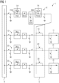
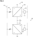
- FIGS 1 and 2 schematically show embodiments of the arrangement according to the invention.
- the DC side of the first converter is connected to a DC network 109 (a first bus bar of the DC network) via an arrangement 110 according to the embodiment shown in figure 1 .
- the DC side of the second converter 102 is connected to the DC network 109 (a second bus bar of the DC network) via another arrangement 111 as shown in figure 1 .
Landscapes
- Engineering & Computer Science (AREA)
- Power Engineering (AREA)
- Direct Current Feeding And Distribution (AREA)
Abstract
Description
- The present invention relates to a high-voltage power transmission arrangement.
- Generally, a DC network (DC grid) comprises one or several connected DC lines. In addition, DC networks usually comprise further DC network elements to initiate and/or operate the power transmission through the network, namely power exchange elements such as converters (AC/DC and/or DC/DC), energy storage devices, DC choppers, DC cables, DC overhead lines (or cables), DC circuit breakers, energy sources (e.g. PV plants) and suitable loads. The present invention particularly relates to HVDC networks, i.e. networks with a nominal voltage of more than 100 kV DC.
- In contrast to known and implemented point-to-point HVDC connections, HVDC multi-terminal or meshed systems generally have the task of connecting more than one DC line, more than two AC/DC converters and other operating equipment.
- In an HVDC switching station, DC network elements are connected to a main bus via devices providing the necessary functionalities to open and close the connection between the respective element and the bus, during normal operation as well as under fault conditions. The set of devices installed between the main bus and the network element is usually referred to as a gate. Depending on switching conditions and reliability requirements, the amount of equipment needed and thus the investment costs for a switching station can be significant.
- The object of the present invention is therefore to provide a high-voltage power transmission arrangement as cost-effective and reliable as possible.
- This object is according to a first aspect achieved by an arrangement according to claim 1.
- According to the invention, the high-voltage power transmission arrangement comprises a first DC network element, a second DC network element, a main bus connected to the first DC network element via a first main gate, and with the second DC network element via a second main gate, a transfer bus connected to the first DC network element via a first transfer switch, with the second DC network element via a second transfer switch, and with the main bus via a transfer gate, wherein each of the main and transfer gates comprises a fault separation device and a residual current switch. The transfer gate can be configured in parallel to any other gate by means of the transfer bus. As the transfer gate comprises functionalities for opening the connection between the transfer bus and the main bus, it can re-open immediately upon unsuccessful closing (e.g., a persisting fault condition in an energized network element). After coupling the network element with the main bus via the transfer gate, the transfer gate is by-passed by closing the corresponding main gate. Deactivation of a peak current suppression functionality of the transfer bus is not necessary at any time. The arrangement according to the invention provides an improved switching station significantly reducing the amount of installed equipment but adding increased availability of network elements during gate maintenance.
- In most applications the first and/or the second DC network elements each comprise DC operating equipment, in particular a DC transmission line and/or an AC/DC converter.
- Preferably, the first and/or the second transfer switch are disconnectors. Disconnectors are relatively cost-efficient devices with low breaking capacity, which effectively disconnect a line after the current has been interrupted by some other switching device.
- According to an embodiment of the invention, the transfer gate comprises a discharging device. The discharging device can comprise a discharge switch connected between the transfer bus and an earth potential. The discharge switch allows a discharging of components and provides a path to ground. By discharging and grounding, the arrangement can be reset to its ground/basic state.
- Preferably, the transfer gate comprises a peak current suppression device. The peak current suppression device can comprise a parallel connection of a transfer resistor and a resistor bypass switch. When one of the network elements is being connected to the main bus, the transfer resistor is able to bear the voltage difference between the main bus and the DC side of the network element and to limit the current. If the network element, e.g., a converter is not yet or only partly charged (in case the converter is a modular multilevel converter with switching modules each comprising a separate energy storage, then the energy storages are being charged), then the transfer resistor can limit the charging currents in the transfer bus and the converter. Subsequently, the resistor bypass switch can be closed to establish direct connection with the network element. By closing the resistor bypass switch, the peak current suppression device is deactivated. The deactivation of the current suppression function is advantageous when the transfer gate is used as a substitute for a regular gate during maintenance. In this case the transfer gate will constantly carry the operational currents of the corresponding element. The remaining gates in the switching station are still able to open. However, discharge and current suppression functionalities are not available during this period.
- The fault separation device can comprise a parallel connection of a surge arrester and a fault current switch that is able to open under fault current conditions in a way that the current is commutated into the arrester. In this context, fault separation is understood as suppressing currents (e.g., fault currents) flowing into a predefined network area.
- According to an embodiment of the invention each of the transfer and main gates comprise a disconnecting switch. The disconnecting switches provide a galvanic isolation between the main bus and the network elements in case the network elements shall be disconnected from each other.
- According to another embodiment said transfer gate further comprises a current sensing device and/or a voltage sensing device. The current and/or voltage measurements can be used for a suitable control of the current and/or voltage in the DC node, particularly at a DC side of a converter.
- The transfer gate can further comprise a converter for an active damping of voltage fluctuations. The converter can be used to replace other damping equipment such as resistors or choking coils.
- The present invention further relates to a bipole HVDC station. Such stations often constitute an integral part of a DC network, where the converters of the HVDC station are network elements which shall be connected to the DC network in a possibly cost-efficient and reliable manner.
- In accordance with the present invention, the bipole HVDC station comprises a first converter connected to a positive DC pole via an arrangement according to claim 1 and a second converter connected to a negative DC pole via another arrangement according to claim 1. The first converter is arranged between the positive DC pole and a neutral pole, whereas the second converter is arranged between the neutral pole and the negative pole. The neutral pole can hereby comprise a ground electrode, i.e., a non-insulated conductor system buried into ground or sea, designed for continuous operational currents.
- The arrangement presented above is designed for a full functionality of each main gate in the switching station. When individual functions, such as fault separation, peak current suppression or controlled discharge are not required within a specific gate, unnecessary devices may be omitted without impacting the overall concept.
- The invention will be further explained with reference to example embodiments illustrated in the
figures 1 and2 . -
Figures 1 and2 schematically show embodiments of the arrangement according to the invention. -
Figure 1 shows a high-voltage power transmission arrangement 1. The arrangement 1 comprises a firstDC network element 11, which is a DC transmission line, a secondDC network element 21, which is another DC transmission line, and a thirdDC network element 31, which is a third transmission line. It further comprises amain bus 4 connected to the firstDC network element 11 via a firstmain gate 12, and with the secondDC network element 21 via a secondmain gate 22. Correspondingly, thethird network element 13 is connected to themain bus 4 via a thirdmain gate 32. Further, atransfer bus 5 is provided, thetransfer bus 5 being connected to the firstDC network element 11 via afirst transfer switch 13, with the secondDC network element 21 via asecond transfer switch 23, and with themain bus 4 via a transfer gate 6. Each of the main andtransfer gates - The transfer gate 6 further comprises a discharging device being an element discharge switch EDS. The element discharge switch EDS is designed to discharge any of the
network elements -
Figure 1 only shows the arrangement for a single pole. However, in bipole applications the transfer gate can be utilized for both poles. Considering layout, operational and reliability constraints, it appears advantageous to duplicate the concept shown infigure 1 for the other pole, thus obtaining the arrangement shown infigure 2. Figure 2 shows thereby abipole converter station 100 with afirst converter 101, arranged between a positive and aneutral pole second converter 102 arranged between theneutral pole 104 and anegative pole 105. Both, the first and thesecond converter AC side 106 connected to anAC grid 107 and aDC side 108. The DC side of the first converter is connected to a DC network 109 (a first bus bar of the DC network) via an arrangement 110 according to the embodiment shown infigure 1 . Correspondingly, the DC side of thesecond converter 102 is connected to the DC network 109 (a second bus bar of the DC network) via anotherarrangement 111 as shown infigure 1 .
Claims (10)
- High-voltage power transmission arrangement (1) comprising- a first DC network element (11),- a second DC network element (21),- a main bus (4) connected to
the first DC network element (11) via a first main gate (12), and the second DC network (21) element via a second main gate (22),- a transfer bus (5) connected tothe first DC network element (11) via a first transfer switch (13),the second DC network element (21) via a second transfer switch (23), and tothe main bus (4) via a transfer gate (6), wherein each of the main and transfer gates (12, 22, 6) comprises a fault separation device (FSD) and a residual current switch (RCS). - Arrangement according to claim 1, wherein the first and/or the second DC network elements (11, 21) each comprise DC operating equipment, in particular a DC transmission line and/or an AC/DC converter.
- Arrangement according to one of the claims 1 or 2, wherein the first and/or the second transfer switches (12, 22) are disconnectors.
- Arrangement according to one of the preceding claims, wherein the transfer gate comprises a discharging device (EDS).
- Arrangement according to one of the preceding claims, wherein the transfer gate comprises a peak current suppression device (PCSD).
- Arrangement according to one of the preceding claims, wherein the fault separation device (FSD) comprises a parallel connection of a surge arrester (SA) and a fault current switch (FCS).
- Arrangement according to one of the preceding claims, wherein each of the transfer and main gates (12, 22, 6) comprise a disconnecting switch.
- Arrangement (1) according to any of the preceding claims, wherein said transfer gate (6) further comprises a current sensing device and/or a voltage sensing device.
- Arrangement (1) according to any of the preceding claims, wherein said transfer gate (6) further comprises a converter for an active damping of voltage fluctuations.
- Bipole HVDC station (100) comprising a first converter (101) connected to a positive DC pole (103) via an arrangement (111) according to claim 1 and a second converter (102) connected to a negative DC pole (105) via another arrangement (111) according to claim 1.
Priority Applications (1)
| Application Number | Priority Date | Filing Date | Title |
|---|---|---|---|
| EP22217181.1A EP4395100A1 (en) | 2022-12-29 | 2022-12-29 | High-voltage power transmission arrangement |
Applications Claiming Priority (1)
| Application Number | Priority Date | Filing Date | Title |
|---|---|---|---|
| EP22217181.1A EP4395100A1 (en) | 2022-12-29 | 2022-12-29 | High-voltage power transmission arrangement |
Publications (1)
| Publication Number | Publication Date |
|---|---|
| EP4395100A1 true EP4395100A1 (en) | 2024-07-03 |
Family
ID=84689110
Family Applications (1)
| Application Number | Title | Priority Date | Filing Date |
|---|---|---|---|
| EP22217181.1A Pending EP4395100A1 (en) | 2022-12-29 | 2022-12-29 | High-voltage power transmission arrangement |
Country Status (1)
| Country | Link |
|---|---|
| EP (1) | EP4395100A1 (en) |
Citations (2)
| Publication number | Priority date | Publication date | Assignee | Title |
|---|---|---|---|---|
| US5619076A (en) * | 1994-12-19 | 1997-04-08 | General Signal Power Systems, Inc. | Method and apparatus for connection and disconnection of batteries to uninterruptible power systems and the like |
| WO2013139392A1 (en) * | 2012-03-21 | 2013-09-26 | Abb Technology Ltd | Switching system for a dc grid |
-
2022
- 2022-12-29 EP EP22217181.1A patent/EP4395100A1/en active Pending
Patent Citations (2)
| Publication number | Priority date | Publication date | Assignee | Title |
|---|---|---|---|---|
| US5619076A (en) * | 1994-12-19 | 1997-04-08 | General Signal Power Systems, Inc. | Method and apparatus for connection and disconnection of batteries to uninterruptible power systems and the like |
| WO2013139392A1 (en) * | 2012-03-21 | 2013-09-26 | Abb Technology Ltd | Switching system for a dc grid |
Non-Patent Citations (2)
| Title |
|---|
| "IEC TS 63291-1 ED1: HVDC Grid Systems and connected Converter Stations - Functional Specifications -<br /> Part 1: Guidelines", 24 December 2021 (2021-12-24), pages 1 - 121, XP082031545, Retrieved from the Internet <URL:https://api.iec.ch/harmonized/documents/download/1153903> [retrieved on 20211224] * |
| BARNES MIKE ET AL: "HVDC Circuit Breakers-A Review", IEEE ACCESS, IEEE, USA, vol. 8, 23 November 2020 (2020-11-23), pages 211829 - 211848, XP011825270, DOI: 10.1109/ACCESS.2020.3039921 * |
Similar Documents
| Publication | Publication Date | Title |
|---|---|---|
| RU2397591C2 (en) | Transmission system | |
| EP2856590B1 (en) | Method of fault clearance | |
| EP4138246A1 (en) | Dc power distribution architecture and method applicable to data centers | |
| EP3036813B1 (en) | Electric protection on ac side of hvdc | |
| US11837867B2 (en) | HVDC transmission schemes | |
| US11502641B2 (en) | Photovoltaic string combiner box with protection functions | |
| CN101297448B (en) | converter station | |
| EP2633597A1 (en) | Voltage balancing of symmetric hvdc monopole transmission lines after earth faults | |
| EP3711128A1 (en) | Fault handling in a dc power system | |
| US12184064B2 (en) | Arrangement and method for connecting and/or disconnecting a plurality of dc sub-networks | |
| CN104823345A (en) | Systems and methods for power transmission with cable segment failover support | |
| WO2015090365A1 (en) | Integrated series converter and circuit breaker in a power system | |
| EP1974431B1 (en) | A converter station | |
| Jeong et al. | Protective Coordination Strategy Integrated with Fault Control Scheme for Multi-Terminal MVDC Distribution Networks | |
| Dadgostar et al. | Fast and Discriminative DC Grid Protection Using Bus-bar Capacitor Current | |
| WO2026087427A1 (en) | Circuit breaker with internal power supply |
Legal Events
| Date | Code | Title | Description |
|---|---|---|---|
| PUAI | Public reference made under article 153(3) epc to a published international application that has entered the european phase |
Free format text: ORIGINAL CODE: 0009012 |
|
| STAA | Information on the status of an ep patent application or granted ep patent |
Free format text: STATUS: THE APPLICATION HAS BEEN PUBLISHED |
|
| AK | Designated contracting states |
Kind code of ref document: A1 Designated state(s): AL AT BE BG CH CY CZ DE DK EE ES FI FR GB GR HR HU IE IS IT LI LT LU LV MC ME MK MT NL NO PL PT RO RS SE SI SK SM TR |
|
| STAA | Information on the status of an ep patent application or granted ep patent |
Free format text: STATUS: REQUEST FOR EXAMINATION WAS MADE |
|
| 17P | Request for examination filed |
Effective date: 20240802 |
|
| RBV | Designated contracting states (corrected) |
Designated state(s): AL AT BE BG CH CY CZ DE DK EE ES FI FR GB GR HR HU IE IS IT LI LT LU LV MC ME MK MT NL NO PL PT RO RS SE SI SK SM TR |