EP4395078A1 - Automotive luminous device - Google Patents
Automotive luminous device Download PDFInfo
- Publication number
- EP4395078A1 EP4395078A1 EP22217447.6A EP22217447A EP4395078A1 EP 4395078 A1 EP4395078 A1 EP 4395078A1 EP 22217447 A EP22217447 A EP 22217447A EP 4395078 A1 EP4395078 A1 EP 4395078A1
- Authority
- EP
- European Patent Office
- Prior art keywords
- luminous device
- connector
- main support
- automotive
- automotive luminous
- Prior art date
- Legal status (The legal status is an assumption and is not a legal conclusion. Google has not performed a legal analysis and makes no representation as to the accuracy of the status listed.)
- Granted
Links
Images


Classifications
-
- F—MECHANICAL ENGINEERING; LIGHTING; HEATING; WEAPONS; BLASTING
- F21—LIGHTING
- F21S—NON-PORTABLE LIGHTING DEVICES; SYSTEMS THEREOF; VEHICLE LIGHTING DEVICES SPECIALLY ADAPTED FOR VEHICLE EXTERIORS
- F21S41/00—Illuminating devices specially adapted for vehicle exteriors, e.g. headlamps
- F21S41/10—Illuminating devices specially adapted for vehicle exteriors, e.g. headlamps characterised by the light source
- F21S41/19—Attachment of light sources or lamp holders
- F21S41/192—Details of lamp holders, terminals or connectors
-
- F—MECHANICAL ENGINEERING; LIGHTING; HEATING; WEAPONS; BLASTING
- F21—LIGHTING
- F21S—NON-PORTABLE LIGHTING DEVICES; SYSTEMS THEREOF; VEHICLE LIGHTING DEVICES SPECIALLY ADAPTED FOR VEHICLE EXTERIORS
- F21S43/00—Signalling devices specially adapted for vehicle exteriors, e.g. brake lamps, direction indicator lights or reversing lights
- F21S43/10—Signalling devices specially adapted for vehicle exteriors, e.g. brake lamps, direction indicator lights or reversing lights characterised by the light source
- F21S43/19—Attachment of light sources or lamp holders
- F21S43/195—Details of lamp holders, terminals or connectors
-
- H—ELECTRICITY
- H05—ELECTRIC TECHNIQUES NOT OTHERWISE PROVIDED FOR
- H05K—PRINTED CIRCUITS; CASINGS OR CONSTRUCTIONAL DETAILS OF ELECTRIC APPARATUS; MANUFACTURE OF ASSEMBLAGES OF ELECTRICAL COMPONENTS
- H05K1/00—Printed circuits
- H05K1/02—Details
- H05K1/14—Structural association of two or more printed circuits
- H05K1/148—Arrangements of two or more hingeably connected rigid printed circuit boards, i.e. connected by flexible means
Definitions
- This invention belongs to the field of the arrangements of the elements of an automotive luminous device.
- Automotive lighting market can be considered one of the most competitive ones and new lighting functions are constantly required.
- harnesses create some electromagnetic problems caused by antenna structures created by the harnesses and by the loops in the electric signals.
- the present invention provides an alternative solution for these problems by means of an automotive luminous device.
- a rigid substrate should be understood in the sense of what the skilled person would construe. A skilled person knows the difference between a rigid substrate and a flexible substrate. Although every material is “flexible” in the sense that it has a stress-strain curve, a substrate which does not apparently deform by its own weight when held by one of its ends is deemed to be rigid, while a substrate which suffer a substantial deformation when held by one of its ends is considered to be flexible. In any case, board manufacturers offer a "flexible” model and a "rigid” model, while any skilled person knows the difference between them.
- the rigid plane substrates can be reliably connected despite they may be oriented in different planes. Further, there is no need to provide a connector per each substrate, since a single connector may be used to connect both substrates.
- the main support is a housing, an optical element, or a bezel.
- the connector may be installed in any of these elements, that can be found in standard automotive lighting devices.
- the main support is an auxiliary part installed in a housing, an optical element, or a bezel.
- the optical element is a reflector, a lens or a light guide.
- the fixing means comprises a screw.
- a screw is adequate, because it prevents the connector from moving in the vertical direction (the direction of the insertion of the screw) and also in a plane perpendicular to the insertion direction. Further, if the torque is enough, the screw is also useful to prevent rotation of the connector, so that the conductive wires do not deviate from the corresponding terminals.
- a pin or a longitudinal protrusion may match in the corresponding hollow portion to ensure anti-rotation properties.
- the fixing means comprises a clip joint.
- Figures 2a and 2b show the shape of the conductive wires in rest and when installed in the automotive luminous device of the invention.
- Figure 2a shows the arrangement of the conductive wires 9 of a connector 7 which is to be installed in an automotive luminous device of the invention.
- Figures 5 and 6 show different examples of the relative orientation of the rigid printed circuit boards 1, 2 in different embodiments of an automotive lighting device according to the invention.
Landscapes
- Engineering & Computer Science (AREA)
- General Engineering & Computer Science (AREA)
- Microelectronics & Electronic Packaging (AREA)
- Non-Portable Lighting Devices Or Systems Thereof (AREA)
Abstract
Description
- This invention belongs to the field of the arrangements of the elements of an automotive luminous device.
- Automotive lighting market can be considered one of the most competitive ones and new lighting functions are constantly required.
- There are some luminous designs where light needs to be emitted from different light sources in different planes or different directions. This is often used in some signalling functions, where tight space and car manufacturers' specifications require some creative solutions. Further, long printed circuit boards are not always the best solution, and connection between smaller printed circuit boards are needed. Several groups of harnesses are needed to provide the electric connection between different substrates, and this is not always possible, due to tight space within lighting devices.
- Further, these harnesses create some electromagnetic problems caused by antenna structures created by the harnesses and by the loops in the electric signals.
- Flexible solutions are usually expensive, so a new way of arranging these substrates is sought, to avoid or at least mitigate the aforementioned problems.
- The present invention provides an alternative solution for these problems by means of an automotive luminous device.
- This automotive luminous device comprises
- a main support;
- a first rigid plane substrate arranged on the main support and comprising first terminals;
- a second rigid plane substrate arranged on the main support and comprising second terminals, wherein at least one of the rigid plane substrates comprises at least one light source; and
- a connector comprising a connector body and a plurality of conductive wires, each conductive wire comprising a first end elastically deformed against one of the first terminals and a second end elastically deformed against one of the second terminals, in such a way that each end of each conductive wire exerts a recovery force against the corresponding terminal and in such a way each conductive wire provides electric connection between one first terminal and one second terminal.
- The connector comprises fixing means to create a joint between the connector and the main support, wherein the fixing means are configured to prevent rotation and translation between the connector and the main support.
- A rigid substrate should be understood in the sense of what the skilled person would construe. A skilled person knows the difference between a rigid substrate and a flexible substrate. Although every material is "flexible" in the sense that it has a stress-strain curve, a substrate which does not apparently deform by its own weight when held by one of its ends is deemed to be rigid, while a substrate which suffer a substantial deformation when held by one of its ends is considered to be flexible. In any case, board manufacturers offer a "flexible" model and a "rigid" model, while any skilled person knows the difference between them.
- With this connector, the rigid plane substrates can be reliably connected despite they may be oriented in different planes. Further, there is no need to provide a connector per each substrate, since a single connector may be used to connect both substrates.
- In some particular embodiments, the main support is a housing, an optical element, or a bezel.
- The connector may be installed in any of these elements, that can be found in standard automotive lighting devices.
- In some particular embodiments, the main support is an auxiliary part installed in a housing, an optical element, or a bezel.
- It is often useful to put an auxiliary part between the main support and the connector, since it is sometimes advisable that the connector is higher than the substrates, so that the conductive wires may be arranged to exert the suitable force against the terminals.
- In some particular embodiments, the optical element is a reflector, a lens or a light guide.
- In some particular embodiments, the fixing means comprises a screw.
- A screw is adequate, because it prevents the connector from moving in the vertical direction (the direction of the insertion of the screw) and also in a plane perpendicular to the insertion direction. Further, if the torque is enough, the screw is also useful to prevent rotation of the connector, so that the conductive wires do not deviate from the corresponding terminals.
- In some particular embodiments, the fixing means comprises a protrusion and the main support comprises a hollow portion configured to receive the protrusion.
- An auxiliar protrusion is also useful to prevent the connector from rotate with respect to the substrates, so that the conductive wires do not deviate from the corresponding terminals.
- In some particular embodiments, the protrusion is a pin or a longitudinal protrusion.
- A pin or a longitudinal protrusion may match in the corresponding hollow portion to ensure anti-rotation properties.
- In some particular embodiments, the fixing means comprises a clip joint.
- A clip joint, which may be designed in the connector or in the main support, is also a good option for fixing the connector to the main support.
- In some particular embodiments, the first rigid plane substrate and the second rigid plane substrate are parallel or contained in the same plane.
- Standard lighting devices comprises different substrates which are contained in the same plane. This is the case when the surface to be lit is too large or when the electronics require splitting between different substrates.
- In some particular embodiments, the first rigid plane substrate and the second rigid plane substrate form an angle comprised between 60° and 300°.
- The invention may also be applied when the two rigid plane substrates are not contained in the same plane or in parallel planes. The effect of the force exerted by the conductive wires can be applied in the case of this relative inclination between the substrates.
- The angle between the rigid plane substrates is measured in the faces which contains the terminals which are contacted by the conductive wires.
- In some particular embodiments, the connector is installed on a raising element, so that the distance between the connector and the main support is greater than the distance between the rigid plane substrates and the main support.
- In some particular embodiments, each rigid plane substrate comprises an optical element arranged to receive the light emitted by the corresponding light source and project the light in a projection direction.
- An optical element is an element that has some optical properties to receive a light beam and emit it in a certain direction and/or shape, as a person skilled in automotive lighting would construe without any additional burden. Reflectors, collimators, light guides, projection lenses, etc., or the combination thereof are some examples of these optical elements which are useful for transforming the light beams emitted by the light source into an acceptable light pattern for the functionality chosen for the lighting device.
- In some particular embodiments, the automotive luminous device further comprises an outer lens configured to receive light emitted by the light sources and project it outside the luminous device.
- In some particular embodiments, the light sources are solid-state light sources.
- The term "solid state" refers to light emitted by solid-state electroluminescence, which uses semiconductors to convert electricity into light. Compared to incandescent lighting, solid state lighting creates visible light with reduced heat generation and less energy dissipation. The typically small mass of a solid-state electronic lighting device provides for greater resistance to shock and vibration compared to brittle glass tubes/bulbs and long, thin filament wires. They also eliminate filament evaporation, potentially increasing the lifespan of the illumination device. Some examples of these types of lighting comprise semiconductor light-emitting diodes (LEDs), organic light-emitting diodes (OLED), or polymer light-emitting diodes (PLED) as sources of illumination rather than electrical filaments, plasma or gas.
- Unless otherwise defined, all terms (including technical and scientific terms) used herein are to be interpreted as is customary in the art. It will be further understood that terms in common usage should also be interpreted as is customary in the relevant art and not in an idealised or overly formal sense unless expressly so defined herein.
- In this text, the term "comprises" and its derivations (such as "comprising", etc.) should not be understood in an excluding sense, that is, these terms should not be interpreted as excluding the possibility that what is described and defined may include further elements, steps, etc.
- To complete the description and in order to provide for a better understanding of the invention, a set of drawings is provided. Said drawings form an integral part of the description and illustrate an embodiment of the invention, which should not be interpreted as restricting the scope of the invention, but just as an example of how the invention can be carried out. The drawings comprise the following figures:
-
Figure 1 shows a portion of a first embodiment of an automotive luminous device according to the invention. -
Figures 2a and 2b show the shape of the conductive wires in rest and when installed in the automotive luminous device of the invention. -
Figure 3 shows a detail of an alternative arrangement of the screw in a different embodiment of an automotive luminous device according to the invention. -
Figure 4 shows a plan view of the arrangement of the conductive wires around the screw, to avoid any short circuit. -
Figures 5 and 6 show different examples of the relative orientation of the rigid printed circuit boards in different embodiments of an automotive lighting device according to the invention. -
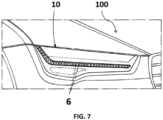
Figure 7 shows an automotiveluminous device 10 according to the invention, installed in anautomotive vehicle 100. - In these figures, the following reference numbers have been used
- 1
- First printed circuit board
- 2
- Second printed circuit board
- 3
- Housing
- 4
- First electric terminal
- 5
- Second electric terminal
- 6
- LED
- 7
- Connector
- 8
- Connector body
- 9
- Conductive wires
- 10
- Headlamp
- 11
- First end of the conductive wire
- 12
- Second end of the conductive wire
- 13
- Screw
- 14
- Rising part
- 15
- Reflector
- 16
- Outer lens
- 17
- Pin
- 18
- Hollow receptacle for the pin
- The example embodiments are described in sufficient detail to enable those of ordinary skill in the art to embody and implement the systems and processes herein described. It is important to understand that embodiments can be provided in many alternate forms and should not be construed as limited to the examples set forth herein.
- Accordingly, while embodiment can be modified in various ways and take on various alternative forms, specific embodiments thereof are shown in the drawings and described in detail below as examples. There is no intent to limit to the particular forms disclosed. On the contrary, all modifications, equivalents, and alternatives falling within the scope of the appended claims should be included. Elements of the example embodiments are consistently denoted by the same reference numerals throughout the drawings and detailed description where appropriate.
-
Figure 1 shows a portion of a first embodiment of an automotive luminous device according to the invention. - In this portion, the following elements are found: a portion of a
housing 3, a first rigid printedcircuit board 1 arranged on the housing, a second printedcircuit board 2 arranged on thehousing 3 and aconnector 7 which is intended to create an electric connection between both printedcircuit boards - The first printed
circuit board 1 comprises firstelectric terminals 4 and the second printedcircuit board 2 comprises threeLEDs 6 and secondelectric terminals 5. TheLEDs 6 of the second printedcircuit board 2 are intended to be commanded by instructions received at the first printedcircuit board 1, so an electric connection between both printedcircuit boards - The
connector 7 comprises aconnector body 8 and a plurality ofconductive wires 9, the same number of conductive wires as the first andsecond terminals circuit board 1 and the second printedcircuit board 2 comprises five terminals, theconnector 7 comprises fiveconductive wires 9. - Each
conductive wire 9 has afirst end 11 elastically deformed against one of thefirst terminals 4 and asecond end 12 elastically deformed against one of thesecond terminals 5, in such a way that each end of eachconductive wire 9 exerts a recovery force against the correspondingterminal first terminal 4 and onesecond terminal 5, eachconductive wire 9 provides electric connection between onefirst terminal 4 and onesecond terminal 5. - Further, the
connector 7 comprises ascrew 13 to create a joint between theconnector 7 and thehousing 3. Thescrew 13 is installed with a torque enough to prevent rotation between theconnector 7 and thehousing 3. Because of the nature of thescrew 13, translation in any direction is also not allowed. - In this case, the
connector 7 is installed in a portion of thehousing 3. However, in different embodiments, it could be installed in an optical element or in a bezel. Even in other embodiments, an auxiliary part may be installed in any of these locations, and provide support for the connector. -
Figures 2a and 2b show the shape of the conductive wires in rest and when installed in the automotive luminous device of the invention. -
Figure 2a shows the arrangement of theconductive wires 9 of aconnector 7 which is to be installed in an automotive luminous device of the invention. - As seen in this figure, when the
conductive wires 9 are in rest, their position is low. This is not due to its weight, but to the intentional shape provided to the wires. -
Figure 2b shows the arrangement of theconductive wires 9 of theconnector 7 when the printedcircuit boards - In this case, the printed circuit boards are contained in the same plane. In any case, it is observed how the
conductive wires 9 are deformed to match the position against the correspondingconductive terminals - Due to this deformation, there is a force that presses each conductive wire against the corresponding
terminals - In this
figure 2b , it is observed how theconnector 7 is installed on a raisingelement 14, so that the distance between theconnector 7 and thehousing 3 is greater than the distance between therigid plane substrates housing 3. Therefore, the force may be controlled to be optimal. -
Figure 3 shows a detail of an alternative arrangement of thescrew 13 in a different embodiment of an automotive luminous device according to the invention. - In this case, the torque of the screw is not carefully controlled, and the
screw 13 is only used to prevent linear movements in any of the three dimensions of the space. - Rotation is prevented by the insertion of a
protrusion 17 in ahollow portion 18 located in thehousing 3. In this case, the protrusion is anellipsoidal pin 17, but this protrusion could have any shape provided that the corresponding hollow portion has a matching shape which prevents rotation. - In these cases, the screw could be replaced by a clip joint, since the prevention of rotation is now provided by a different element.
-
Figure 4 shows a plan view of the arrangement of theconductive wires 9 around thescrew 13, to avoid any short circuit. - As seen in this figure, the
conductive wires 9 are bended to avoid contacting thescrew 13, which crosses theconnector body 8 until threading in the corresponding threaded portion of thehousing 3. Theconductive wires 9 provide the electric connection between thefirst terminals 4 and thesecond terminals 5 without contacting any other conductive element, thus avoiding a short circuit. -
Figures 5 and 6 show different examples of the relative orientation of the rigid printedcircuit boards - In
figure 5 , the rigid printed circuit boards are provided forming an angle of 120°. The angle is measured in the faces which contain theterminals terminals Figures 2a and 2b , the electric connection is ensured. - In
figure 6 , the rigid printed circuit boards are provided forming an angle of 240°. The angle is measured in the faces which contain theterminals terminals Figures 2a and 2b , the electric connection is ensured. -
Figure 7 shows an automotiveluminous device 10 according to the invention, installed in anautomotive vehicle 100. The light emitted by the LEDs of the second printedcircuit board 2 is reflected by a reflector 15 and projected outside theluminous device 10 by an outer lens 16.
Claims (14)
- Automotive luminous device (10) comprisinga main support (3);a first rigid plane substrate (1) arranged on the main support (3) and comprising first terminals (4);a second rigid plane substrate (2) arranged on the main support and comprising second terminals (5),wherein at least one of the rigid plane substrates (1, 2) comprises at least one light source (6); anda connector (7) comprising a connector body (8) and a plurality of conductive wires (9), each conductive wire (9) comprising a first end (11) elastically deformed against one of the first terminals (4) and a second end (12) elastically deformed against one of the second terminals (5), in such a way that each end of each conductive wire (9) exerts a recovery force against the corresponding terminal (4, 5) and in such a way that each conductive wire (9) provides electric connection between one first terminal (4) and one second terminal (5);wherein the connector (7) comprises fixing means (13) to create a joint between the connector and the main support, wherein the fixing means are configured to prevent rotation and translation between the connector and the main support.
- Automotive luminous device (10) according to claim 1, wherein the main support is a housing, an optical element, or a bezel.
- Automotive luminous device (10) according to claim 1, wherein the main support is an auxiliary part installed in a housing, an optical element, or a bezel.
- Automotive luminous device (10) according to any of claims 2 or 3, wherein the optical element is a reflector, a lens or a light guide.
- Automotive luminous device (10) according to any of the preceding claims, wherein the fixing means comprises a screw (13).
- Automotive luminous device (10) according to any of the preceding claims, wherein the fixing means comprises a protrusion and the main support comprises a hollow portion configured to receive the protrusion.
- Automotive luminous device (10) according to claim 6, wherein the protrusion is a pin or a longitudinal protrusion.
- Automotive luminous device (10) according to any of the preceding claims, wherein the fixing means comprises a clip joint.
- Automotive luminous device (10) according to any of the preceding claims, wherein the first rigid plane substrate (1) and the second rigid plane substrate (2) are parallel or contained in the same plane.
- Automotive luminous device (10) according to any of claims 1 to 8, wherein the first rigid plane substrate (1) and the second rigid plane substrate (2) form an angle comprised between 60° and 300°.
- Automotive luminous device (10) according to any of the preceding claims, wherein the connector is installed on a raising element (14), so that the distance between the connector and the main support is greater than the distance between the rigid plane substrates and the main support.
- Automotive luminous device according to any of the preceding claims, wherein each rigid plane substrate (1, 2) comprises an optical element (15) arranged to receive the light emitted by the corresponding light source (6) and project the light in a projection direction.
- Automotive luminous device according to any of the preceding claims, further comprising an outer lens (16) configured to receive light emitted by the light sources and project it outside the luminous device.
- Automotive luminous device (10) according to any of the preceding claims, wherein the light sources (6) are solid-state light sources.
Priority Applications (1)
| Application Number | Priority Date | Filing Date | Title |
|---|---|---|---|
| EP22217447.6A EP4395078B1 (en) | 2022-12-31 | 2022-12-31 | Automotive luminous device |
Applications Claiming Priority (1)
| Application Number | Priority Date | Filing Date | Title |
|---|---|---|---|
| EP22217447.6A EP4395078B1 (en) | 2022-12-31 | 2022-12-31 | Automotive luminous device |
Publications (2)
| Publication Number | Publication Date |
|---|---|
| EP4395078A1 true EP4395078A1 (en) | 2024-07-03 |
| EP4395078B1 EP4395078B1 (en) | 2025-10-08 |
Family
ID=84785149
Family Applications (1)
| Application Number | Title | Priority Date | Filing Date |
|---|---|---|---|
| EP22217447.6A Active EP4395078B1 (en) | 2022-12-31 | 2022-12-31 | Automotive luminous device |
Country Status (1)
| Country | Link |
|---|---|
| EP (1) | EP4395078B1 (en) |
Citations (7)
| Publication number | Priority date | Publication date | Assignee | Title |
|---|---|---|---|---|
| US20030071581A1 (en) * | 2001-10-16 | 2003-04-17 | Panagotacos George W. | Flexible lighting segment |
| US20050213321A1 (en) * | 2004-03-24 | 2005-09-29 | Yuan Lin | Full-color flexible light source device |
| DE102011051153A1 (en) * | 2011-06-17 | 2012-12-20 | Hella Kgaa Hueck & Co. | Electrical connecting device used for connecting electrical component e.g. LED light source in lighting device mounted on motor vehicle, has terminal connector which is deformable, such that distance between contact points is varied |
| US20170179103A1 (en) * | 2014-03-27 | 2017-06-22 | Intel Corporation | Flexible electronic system with wire bonds |
| US20190252810A1 (en) * | 2018-02-09 | 2019-08-15 | Metrospec Technology, L.L.C. | Interconnectable circuit boards adapted for lateral in-plane bending |
| US20220065424A1 (en) * | 2020-08-25 | 2022-03-03 | Hyundai Mobis Co., Ltd. | Light source module and vehicle lamp including the same |
| FR3116588A1 (en) * | 2020-11-20 | 2022-05-27 | Valeo Vision | LIGHTING MODULE FOR A MOTOR VEHICLE |
Family Cites Families (1)
| Publication number | Priority date | Publication date | Assignee | Title |
|---|---|---|---|---|
| DE102006041983A1 (en) * | 2006-09-07 | 2008-03-27 | Robert Bosch Gmbh | A method of electrically connecting a first substrate to a second substrate |
-
2022
- 2022-12-31 EP EP22217447.6A patent/EP4395078B1/en active Active
Patent Citations (7)
| Publication number | Priority date | Publication date | Assignee | Title |
|---|---|---|---|---|
| US20030071581A1 (en) * | 2001-10-16 | 2003-04-17 | Panagotacos George W. | Flexible lighting segment |
| US20050213321A1 (en) * | 2004-03-24 | 2005-09-29 | Yuan Lin | Full-color flexible light source device |
| DE102011051153A1 (en) * | 2011-06-17 | 2012-12-20 | Hella Kgaa Hueck & Co. | Electrical connecting device used for connecting electrical component e.g. LED light source in lighting device mounted on motor vehicle, has terminal connector which is deformable, such that distance between contact points is varied |
| US20170179103A1 (en) * | 2014-03-27 | 2017-06-22 | Intel Corporation | Flexible electronic system with wire bonds |
| US20190252810A1 (en) * | 2018-02-09 | 2019-08-15 | Metrospec Technology, L.L.C. | Interconnectable circuit boards adapted for lateral in-plane bending |
| US20220065424A1 (en) * | 2020-08-25 | 2022-03-03 | Hyundai Mobis Co., Ltd. | Light source module and vehicle lamp including the same |
| FR3116588A1 (en) * | 2020-11-20 | 2022-05-27 | Valeo Vision | LIGHTING MODULE FOR A MOTOR VEHICLE |
Also Published As
| Publication number | Publication date |
|---|---|
| EP4395078B1 (en) | 2025-10-08 |
Similar Documents
| Publication | Publication Date | Title |
|---|---|---|
| EP4078024B1 (en) | Automotive lighting device | |
| US9951910B2 (en) | LED lamp with base having a biased electrical interconnect | |
| US11466831B2 (en) | Printed circuit board, card edge connector socket, electronic assembly and automotive lighting device | |
| US12482966B2 (en) | Electrical connection module and automotive lighting device | |
| EP4395078B1 (en) | Automotive luminous device | |
| EP4203198A1 (en) | Automotive luminous device | |
| US20250202164A1 (en) | Electronic device for an automotive vehicle | |
| EP4431795A1 (en) | Automotive luminous device including fixing means to connect a connector to a substrate | |
| EP4279801B1 (en) | Automotive lighting device with a card edge connector | |
| EP4548435B1 (en) | Automotive luminous device | |
| EP4397902A1 (en) | Luminous module and automotive luminous device | |
| EP4712697A1 (en) | Automotive lighting device for interior lighting | |
| EP4622398A1 (en) | Electronic assembly for an automotive luminous device and an automotive luminous device | |
| EP4203627A1 (en) | Automotive luminous device | |
| EP4412407A1 (en) | Isolated metallic substrate printed circuit board for an automotive luminous device and automotive luminous device | |
| EP3562273A1 (en) | Electronic assembly and lighting device | |
| EP3657067B1 (en) | Automotive lighting device and method for manufacturing an automotive lighting device | |
| EP3450833B1 (en) | Electronic device and lighting module | |
| US12565974B2 (en) | Lighting module with interconnected PCB assemblies | |
| EP3562269A1 (en) | Electronic assembly, lighting device and method for manufacturing a lighting device | |
| US20250372925A1 (en) | Electronic device for an automotive vehicle | |
| JP2018186023A (en) | Luminaire |
Legal Events
| Date | Code | Title | Description |
|---|---|---|---|
| PUAI | Public reference made under article 153(3) epc to a published international application that has entered the european phase |
Free format text: ORIGINAL CODE: 0009012 |
|
| STAA | Information on the status of an ep patent application or granted ep patent |
Free format text: STATUS: THE APPLICATION HAS BEEN PUBLISHED |
|
| AK | Designated contracting states |
Kind code of ref document: A1 Designated state(s): AL AT BE BG CH CY CZ DE DK EE ES FI FR GB GR HR HU IE IS IT LI LT LU LV MC ME MK MT NL NO PL PT RO RS SE SI SK SM TR |
|
| STAA | Information on the status of an ep patent application or granted ep patent |
Free format text: STATUS: REQUEST FOR EXAMINATION WAS MADE |
|
| 17P | Request for examination filed |
Effective date: 20250103 |
|
| GRAP | Despatch of communication of intention to grant a patent |
Free format text: ORIGINAL CODE: EPIDOSNIGR1 |
|
| STAA | Information on the status of an ep patent application or granted ep patent |
Free format text: STATUS: GRANT OF PATENT IS INTENDED |
|
| INTG | Intention to grant announced |
Effective date: 20250430 |
|
| GRAS | Grant fee paid |
Free format text: ORIGINAL CODE: EPIDOSNIGR3 |
|
| GRAA | (expected) grant |
Free format text: ORIGINAL CODE: 0009210 |
|
| STAA | Information on the status of an ep patent application or granted ep patent |
Free format text: STATUS: THE PATENT HAS BEEN GRANTED |
|
| AK | Designated contracting states |
Kind code of ref document: B1 Designated state(s): AL AT BE BG CH CY CZ DE DK EE ES FI FR GB GR HR HU IE IS IT LI LT LU LV MC ME MK MT NL NO PL PT RO RS SE SI SK SM TR |
|
| REG | Reference to a national code |
Ref country code: GB Ref legal event code: FG4D Ref country code: CH Ref legal event code: F10 Free format text: ST27 STATUS EVENT CODE: U-0-0-F10-F00 (AS PROVIDED BY THE NATIONAL OFFICE) Effective date: 20251008 |
|
| REG | Reference to a national code |
Ref country code: DE Ref legal event code: R096 Ref document number: 602022022636 Country of ref document: DE |
|
| REG | Reference to a national code |
Ref country code: IE Ref legal event code: FG4D |
|
| PGFP | Annual fee paid to national office [announced via postgrant information from national office to epo] |
Ref country code: FR Payment date: 20251230 Year of fee payment: 4 |
|
| REG | Reference to a national code |
Ref country code: NL Ref legal event code: MP Effective date: 20251008 |
|
| REG | Reference to a national code |
Ref country code: AT Ref legal event code: MK05 Ref document number: 1845666 Country of ref document: AT Kind code of ref document: T Effective date: 20251008 |
|
| PG25 | Lapsed in a contracting state [announced via postgrant information from national office to epo] |
Ref country code: NL Free format text: LAPSE BECAUSE OF FAILURE TO SUBMIT A TRANSLATION OF THE DESCRIPTION OR TO PAY THE FEE WITHIN THE PRESCRIBED TIME-LIMIT Effective date: 20251008 |
|
| PG25 | Lapsed in a contracting state [announced via postgrant information from national office to epo] |
Ref country code: ES Free format text: LAPSE BECAUSE OF FAILURE TO SUBMIT A TRANSLATION OF THE DESCRIPTION OR TO PAY THE FEE WITHIN THE PRESCRIBED TIME-LIMIT Effective date: 20251008 |
|
| REG | Reference to a national code |
Ref country code: LT Ref legal event code: MG9D |
|
| PG25 | Lapsed in a contracting state [announced via postgrant information from national office to epo] |
Ref country code: NO Free format text: LAPSE BECAUSE OF FAILURE TO SUBMIT A TRANSLATION OF THE DESCRIPTION OR TO PAY THE FEE WITHIN THE PRESCRIBED TIME-LIMIT Effective date: 20260108 |
|
| PGFP | Annual fee paid to national office [announced via postgrant information from national office to epo] |
Ref country code: DE Payment date: 20251231 Year of fee payment: 4 |
|
| PG25 | Lapsed in a contracting state [announced via postgrant information from national office to epo] |
Ref country code: HR Free format text: LAPSE BECAUSE OF FAILURE TO SUBMIT A TRANSLATION OF THE DESCRIPTION OR TO PAY THE FEE WITHIN THE PRESCRIBED TIME-LIMIT Effective date: 20251008 Ref country code: FI Free format text: LAPSE BECAUSE OF FAILURE TO SUBMIT A TRANSLATION OF THE DESCRIPTION OR TO PAY THE FEE WITHIN THE PRESCRIBED TIME-LIMIT Effective date: 20251008 Ref country code: AT Free format text: LAPSE BECAUSE OF FAILURE TO SUBMIT A TRANSLATION OF THE DESCRIPTION OR TO PAY THE FEE WITHIN THE PRESCRIBED TIME-LIMIT Effective date: 20251008 |
|
| PG25 | Lapsed in a contracting state [announced via postgrant information from national office to epo] |
Ref country code: RS Free format text: LAPSE BECAUSE OF FAILURE TO SUBMIT A TRANSLATION OF THE DESCRIPTION OR TO PAY THE FEE WITHIN THE PRESCRIBED TIME-LIMIT Effective date: 20260108 |
|
| PG25 | Lapsed in a contracting state [announced via postgrant information from national office to epo] |
Ref country code: IS Free format text: LAPSE BECAUSE OF FAILURE TO SUBMIT A TRANSLATION OF THE DESCRIPTION OR TO PAY THE FEE WITHIN THE PRESCRIBED TIME-LIMIT Effective date: 20260208 |
|
| PG25 | Lapsed in a contracting state [announced via postgrant information from national office to epo] |
Ref country code: PT Free format text: LAPSE BECAUSE OF FAILURE TO SUBMIT A TRANSLATION OF THE DESCRIPTION OR TO PAY THE FEE WITHIN THE PRESCRIBED TIME-LIMIT Effective date: 20260209 |
|
| PG25 | Lapsed in a contracting state [announced via postgrant information from national office to epo] |
Ref country code: PL Free format text: LAPSE BECAUSE OF FAILURE TO SUBMIT A TRANSLATION OF THE DESCRIPTION OR TO PAY THE FEE WITHIN THE PRESCRIBED TIME-LIMIT Effective date: 20251008 |
|
| PG25 | Lapsed in a contracting state [announced via postgrant information from national office to epo] |
Ref country code: LV Free format text: LAPSE BECAUSE OF FAILURE TO SUBMIT A TRANSLATION OF THE DESCRIPTION OR TO PAY THE FEE WITHIN THE PRESCRIBED TIME-LIMIT Effective date: 20251008 |
|
| PG25 | Lapsed in a contracting state [announced via postgrant information from national office to epo] |
Ref country code: BG Free format text: LAPSE BECAUSE OF FAILURE TO SUBMIT A TRANSLATION OF THE DESCRIPTION OR TO PAY THE FEE WITHIN THE PRESCRIBED TIME-LIMIT Effective date: 20251008 |