EP4395074A1 - Antenna device, system, communication device, and program - Google Patents
Antenna device, system, communication device, and program Download PDFInfo
- Publication number
- EP4395074A1 EP4395074A1 EP22876433.8A EP22876433A EP4395074A1 EP 4395074 A1 EP4395074 A1 EP 4395074A1 EP 22876433 A EP22876433 A EP 22876433A EP 4395074 A1 EP4395074 A1 EP 4395074A1
- Authority
- EP
- European Patent Office
- Prior art keywords
- antenna
- antennas
- communication partner
- distance
- shifted
- Prior art date
- Legal status (The legal status is an assumption and is not a legal conclusion. Google has not performed a legal analysis and makes no representation as to the accuracy of the status listed.)
- Granted
Links
Images












Classifications
-
- H—ELECTRICITY
- H01—ELECTRIC ELEMENTS
- H01Q—ANTENNAS, i.e. RADIO AERIALS
- H01Q21/00—Antenna arrays or systems
- H01Q21/06—Arrays of individually energised antenna units similarly polarised and spaced apart
-
- H—ELECTRICITY
- H01—ELECTRIC ELEMENTS
- H01Q—ANTENNAS, i.e. RADIO AERIALS
- H01Q1/00—Details of, or arrangements associated with, antennas
- H01Q1/27—Adaptation for use in or on movable bodies
- H01Q1/32—Adaptation for use in or on road or rail vehicles
-
- H—ELECTRICITY
- H04—ELECTRIC COMMUNICATION TECHNIQUE
- H04B—TRANSMISSION
- H04B7/00—Radio transmission systems, i.e. using radiation field
- H04B7/02—Diversity systems; Multi-antenna system, i.e. transmission or reception using multiple antennas
- H04B7/04—Diversity systems; Multi-antenna system, i.e. transmission or reception using multiple antennas using two or more spaced independent antennas
-
- H—ELECTRICITY
- H04—ELECTRIC COMMUNICATION TECHNIQUE
- H04B—TRANSMISSION
- H04B7/00—Radio transmission systems, i.e. using radiation field
- H04B7/02—Diversity systems; Multi-antenna system, i.e. transmission or reception using multiple antennas
- H04B7/04—Diversity systems; Multi-antenna system, i.e. transmission or reception using multiple antennas using two or more spaced independent antennas
- H04B7/0404—Diversity systems; Multi-antenna system, i.e. transmission or reception using multiple antennas using two or more spaced independent antennas the mobile station comprising multiple antennas, e.g. to provide uplink diversity
-
- H—ELECTRICITY
- H04—ELECTRIC COMMUNICATION TECHNIQUE
- H04B—TRANSMISSION
- H04B7/00—Radio transmission systems, i.e. using radiation field
- H04B7/14—Relay systems
- H04B7/145—Passive relay systems
-
- H—ELECTRICITY
- H04—ELECTRIC COMMUNICATION TECHNIQUE
- H04B—TRANSMISSION
- H04B1/00—Details of transmission systems, not covered by a single one of groups H04B3/00 - H04B13/00; Details of transmission systems not characterised by the medium used for transmission
- H04B1/38—Transceivers, i.e. devices in which transmitter and receiver form a structural unit and in which at least one part is used for functions of transmitting and receiving
- H04B1/3822—Transceivers, i.e. devices in which transmitter and receiver form a structural unit and in which at least one part is used for functions of transmitting and receiving specially adapted for use in vehicles
-
- H—ELECTRICITY
- H04—ELECTRIC COMMUNICATION TECHNIQUE
- H04B—TRANSMISSION
- H04B7/00—Radio transmission systems, i.e. using radiation field
- H04B7/02—Diversity systems; Multi-antenna system, i.e. transmission or reception using multiple antennas
- H04B7/04—Diversity systems; Multi-antenna system, i.e. transmission or reception using multiple antennas using two or more spaced independent antennas
- H04B7/06—Diversity systems; Multi-antenna system, i.e. transmission or reception using multiple antennas using two or more spaced independent antennas at the transmitting station
- H04B7/0686—Hybrid systems, i.e. switching and simultaneous transmission
- H04B7/0691—Hybrid systems, i.e. switching and simultaneous transmission using subgroups of transmit antennas
-
- H—ELECTRICITY
- H04—ELECTRIC COMMUNICATION TECHNIQUE
- H04B—TRANSMISSION
- H04B7/00—Radio transmission systems, i.e. using radiation field
- H04B7/02—Diversity systems; Multi-antenna system, i.e. transmission or reception using multiple antennas
- H04B7/04—Diversity systems; Multi-antenna system, i.e. transmission or reception using multiple antennas using two or more spaced independent antennas
- H04B7/08—Diversity systems; Multi-antenna system, i.e. transmission or reception using multiple antennas using two or more spaced independent antennas at the receiving station
- H04B7/0868—Hybrid systems, i.e. switching and combining
- H04B7/0874—Hybrid systems, i.e. switching and combining using subgroups of receive antennas
Definitions
- the present invention relates to an antenna apparatus, a system, a communication apparatus, and a program.
- Non-Patent Documents 1 and 2 describe effectiveness of a spatial diversity in vehicle-to-vehicle communication.
- Non-Patent Document 3 describes that antenna spacing for spatial diversity is based on non-line-of-sight communication and that it suffices to have a spacing of a half wavelength or more on a mobile station side and a spacing of 10 wavelengths or more on a base station side.
- the plurality of first antennas may be arranged by being shifted by the distance equivalent to the odd multiple of the half period of the maximum fluctuation period calculated from a minimum value for a distance between the antenna of the communication partner and a reflector.
- the plurality of second antennas may be respectively arranged by being shifted with respect to the plurality of first antennas by the distance equivalent to the odd multiple of the half period of the minimum fluctuation period calculated from respective distances between the antenna of the communication partner and two reflectors in an environment where the antenna apparatus and the communication partner are sandwiched between the two reflectors and from a number of at least one reflection.
- the plurality of first antennas may be arranged by being shifted in a lateral direction by the distance equivalent to the odd multiple of the half period of the maximum fluctuation period calculated from a minimum value for a distance between the antenna of the communication partner and a reflector in an environment where the antenna apparatus and the communication partner are sandwiched between two reflectors located in a lateral direction.
- the antenna apparatus may be an antenna apparatus for a vehicle travelling on a road, at least one of the two reflectors may be a side vehicle travelling on a side of the vehicle, and a distance between the antenna of the communication partner and the side vehicle may be a distance corresponding to the distance between the antenna of the communication partner and the side vehicle which is assumed when the side vehicle travels on a side of the communication partner.
- the plurality of first antennas may be arranged by being shifted in a longitudinal direction by the distance equivalent to the odd multiple of the half period of the maximum fluctuation period calculated from a minimum value for a distance between the antenna of the communication partner and a reflector in an environment where the antenna apparatus and the communication partner are sandwiched between two reflectors located in a longitudinal direction.
- the plurality of second antennas may be respectively arranged by being shifted in a longitudinal direction with respect to the plurality of first antennas by the distance equivalent to the odd multiple of the half period of the minimum fluctuation period calculated from respective distances between the antenna of the communication partner and two reflectors located in a longitudinal direction in an environment where the antenna apparatus and the communication partner are sandwiched between the two reflectors and from a number of at least one reflection.
- the plurality of first antennas may be arranged by being shifted in a lateral direction by the distance equivalent to the odd multiple of the half period of the maximum fluctuation period calculated from a minimum value for a distance between the antenna of the communication partner and a reflector in an environment where a plurality of reflectors are located in a lateral direction of the antenna apparatus and the communication partner, and the plurality of second antennas may be respectively arranged by being shifted in a lateral direction with respect to the plurality of first antennas by the distance equivalent to the odd multiple of the half period of the minimum fluctuation period calculated from respective distances between the antenna of the communication partner and the plurality of reflectors in an environment where the plurality of reflectors are located in a lateral direction of the antenna apparatus and the communication partner.
- the plurality of first antennas may include two first antennas which are arranged by being shifted in a lateral direction by the distance equivalent to the odd multiple of the half period of the maximum fluctuation period calculated from a minimum value for distances between the antenna of the communication partner and two reflectors in a lateral direction in an environment where the antenna apparatus and the communication partner are sandwiched between the two reflectors in the lateral direction
- the plurality of second antennas may include two second antennas which are respectively arranged by being shifted in a lateral direction with respect to the two first antennas by the distance equivalent to the odd multiple of the half period of the minimum fluctuation period calculated from respective distances between the antenna of the communication partner and the two reflectors in the lateral direction in the environment where the antenna apparatus and a communication partner are sandwiched between the two reflectors in the lateral direction and from a number of at least one reflection
- the antenna apparatus may include: two third antennas which are respectively arranged by being shifted in a longitudinal direction with respect to the two first antennas by the distance equivalent to the
- the plurality of first antennas may include two first antennas which are arranged by being shifted in a lateral direction by the distance equivalent to the odd multiple of the half period of the maximum fluctuation period calculated from a minimum value for distances between the antenna of the communication partner and two reflectors in a lateral direction in an environment where the antenna apparatus and the communication partner are sandwiched between the two reflectors in the lateral direction and two reflectors in a longitudinal direction and which are arranged by being shifted in a longitudinal direction by the distance equivalent to the odd multiple of the half period of the maximum fluctuation period calculated from a minimum value for distances between the antenna of the communication partner and the two reflectors in the longitudinal direction
- the plurality of second antennas may include two second antennas which are respectively arranged by being shifted in a lateral direction with respect to the two first antennas by the distance equivalent to the odd multiple of the half period of the minimum fluctuation period calculated from respective distances between the antenna of the communication partner and two reflectors in a lateral direction in the environment where the antenna apparatus and the
- the antenna apparatus may be mounted on a movable object.
- the antenna apparatus may include an antenna array including: a plurality of first antennas which are arranged by being shifted by a distance equivalent to an odd multiple of a half period of a maximum fluctuation period of a radio wave having a longest fluctuation period among a plurality of radio waves transmitted by the antenna apparatus and received by a communication partner; and a plurality of second antennas which are respectively arranged by being shifted with respect to the plurality of first antennas by a distance equivalent to an odd multiple of a half period of a minimum fluctuation period of a radio wave having a shortest fluctuation period among the plurality of radio waves.
- One embodiment of the present invention provides a system including the antenna apparatus and the movable object.
- the communication apparatus may be mounted on a movable object.
- the communication apparatus may include: an antenna array including a plurality of first antennas and a plurality of second antennas.
- the communication apparatus may include a surrounding environment identification unit which identifies a surrounding environment of the movable object mounted with the communication apparatus and a movable object mounted with a communication partner of the communication apparatus.
- the communication apparatus may include an antenna control unit which controls positions of the plurality of first antennas and the plurality of second antennas such that the plurality of first antennas are shifted by a distance equivalent to an odd multiple of a half period of a maximum fluctuation period of a radio wave having a longest fluctuation period among a plurality of radio waves received from an antenna of the communication partner by an antenna apparatus and that the plurality of second antennas are respectively shifted with respect to the plurality of first antennas by a distance equivalent to an odd multiple of a half period of a minimum fluctuation period of a radio wave having a shortest fluctuation period among the plurality of radio waves, on a basis of a result of identification by the surrounding environment identification unit.
- the communication apparatus may be mounted on a movable object.
- the communication apparatus may include: an antenna array including a plurality of first antennas and a plurality of second antennas.
- the communication apparatus may include a surrounding environment identification unit which identifies a surrounding environment of the movable object mounted with the communication apparatus and a movable object mounted with a communication partner of the communication apparatus.
- the communication apparatus may include an antenna control unit which controls positions of the plurality of first antennas and the plurality of second antennas such that the plurality of first antennas are shifted by a distance equivalent to an odd multiple of a half period of a maximum fluctuation period of a radio wave having a longest fluctuation period among a plurality of radio waves transmitted by an antenna apparatus and received by an antenna of the communication partner and that the plurality of second antennas are respectively shifted with respect to the plurality of first antennas by a distance equivalent to an odd multiple of a half period of a minimum fluctuation period of a radio wave having a shortest fluctuation period among the plurality of radio waves, on a basis of a result of identification by the surrounding environment identification unit.
- One embodiment of the present invention provides a program that causes a computer to function as the communication apparatus.
- the antenna apparatus may be mounted on a movable object.
- the antenna apparatus may include an antenna array having a plurality of reception antennas.
- the plurality of reception antennas may be arranged by being shifted by a distance equivalent to an odd multiple of a half period of a fluctuation period of each horizontal and vertical component, assuming that a difference for the horizontal component and the vertical component between a plurality of regular reflection positions on a reflector between a transmission antenna of a communication partner and a first reception antenna of the plurality of reception antennas, and a position of the transmission antenna, is a distance for the horizontal component and the vertical component between the transmission antenna and the reflector, and using a value in a region where a fluctuation period is stable.
- the reflector may be a tunnel inner wall, and the regular reflection positions may be calculated on a basis of dimensions of any tunnel of a plurality of tunnels.
- the reflector may be a tunnel inner wall, and the regular reflection positions may be calculated on a basis of an average value for dimensions of a plurality of tunnels.
- the movable object may be a vehicle, the reflector in a horizontal direction may be a tunnel inner wall, the reflector in a vertical direction may be a road surface, and the plurality of reception antennas may be arranged by being shifted by a distance equivalent to an odd multiple of a half period of a fluctuation period of each horizontal and vertical component, assuming that a difference for each horizontal component between a plurality of regular reflection positions on a tunnel inner wall between the transmission antenna of the communication partner and the first reception antenna, and the position of the transmission antenna, is a distance for each component between the transmission antenna and the tunnel inner wall in a horizontal direction, assuming that a difference for each vertical component between the transmission antenna of the communication partner and a road surface is a distance for each component between the transmission antenna and the road surface in a vertical direction, and using a value in a region where a fluctuation period is stable.
- the movable object may be a vehicle
- the reflector in a horizontal direction may be another vehicle located on a side of the movable object
- the reflector in a vertical direction may be a tunnel inner wall
- the plurality of reception antennas may be arranged by being shifted by a distance equivalent to an odd multiple of a half period of a fluctuation period of each horizontal and vertical component, assuming that a difference for each horizontal component between the transmission antenna of the communication partner and the another vehicle is a distance for each component between the transmission antenna and the another vehicle in a horizontal direction, assuming that a difference for each vertical component between a plurality of regular reflection positions on a tunnel inner wall between the transmission antenna of the communication partner and the first reception antenna, and the position of the transmission antenna, is a distance for each component between the transmission antenna and the tunnel inner wall, and using a value in a region where a fluctuation period is stable.
- the plurality of reception antennas may be arranged by being shifted by a distance equivalent to an odd multiple of a half period of a fluctuation period of each horizontal and vertical component, assuming that the difference for the horizontal component and the vertical component between the plurality of regular reflection positions on the reflector between the transmission antenna of the communication partner and the first reception antenna, and the position of the transmission antenna, is the distance for the horizontal component and the vertical component between the transmission antenna and the reflector, and using a mode value of the horizontal component and the vertical component.
- the plurality of reception antennas may be arranged by being shifted by a distance equivalent to an odd multiple of a half period of a fluctuation period of each horizontal and vertical component ((2j + 1) ⁇ d/2
- the antenna apparatus may be mounted on a movable object.
- the antenna apparatus may include an antenna array having a plurality of transmission antennas.
- the plurality of transmission antennas may be arranged by being shifted by a distance equivalent to an odd multiple of a half period of a fluctuation period of each horizontal and vertical component, assuming that a difference for the horizontal component and the vertical component between a plurality of regular reflection positions on a reflector between a reception antenna of a communication partner and a first transmission antenna of the plurality of transmission antennas, and a position of the reception antenna, is a distance for the horizontal component and the vertical component between the reception antenna and the reflector, and using a value in a region where a fluctuation period is stable.
- One embodiment of the present invention provides a system including the antenna apparatus and the movable object.
- the communication apparatus may be mounted on a movable object.
- the communication apparatus may include an antenna array having a plurality of reception antennas.
- the communication apparatus may include a surrounding environment identification unit which identifies a surrounding environment of the movable object mounted with the communication apparatus and a movable object mounted with a communication partner of the communication apparatus, the surrounding environment identification unit identifying a reflector between the movable object and the communication partner.
- the communication apparatus may include an antenna control unit which controls positions of the plurality of reception antennas such that they are arranged by being shifted by a distance equivalent to an odd multiple of a half period of a fluctuation period of each horizontal and vertical component, assuming that a difference for the horizontal component and the vertical component between a plurality of regular reflection positions on the reflector and a position of the transmission antenna, is a distance for the horizontal component and the vertical component between the transmission antenna and the reflector, and using a value in a region where a fluctuation period is stable.
- the communication apparatus may be mounted on a movable object.
- the communication apparatus may include an antenna array having a plurality of transmission antennas.
- the communication apparatus may include a surrounding environment identification unit which identifies a surrounding environment of the movable object mounted with the communication apparatus and a movable object mounted with a communication partner of the communication apparatus, the surrounding environment identification unit identifying a reflector between the movable object and the communication partner.
- the communication apparatus may include an antenna control unit which controls positions of the plurality of transmission antennas such that they are arranged by being shifted by a distance equivalent to an odd multiple of a half period of a fluctuation period of each horizontal and vertical component, assuming that a difference for the horizontal component and the vertical component between a plurality of regular reflection positions on the reflector and a position of the reception antenna, is a distance for the horizontal component and the vertical component between the reception antenna and the reflector, and using a value in a region where a fluctuation period is stable.
- Non-Patent Document 1 Although it is shown that spatial diversity is effective in vehicle-to-vehicle communication (Non-Patent Document 1), there is no mention of an optimal antenna array configuration method. It is described that antenna spacing for spatial diversity in mobile communication is based on non-line-of-sight communication in general and that it suffices to have a spacing of a half wavelength or more on a mobile station side and a spacing of 10 wavelengths or more on a base station side (Non-Patent Document 2).
- Fig. 1 and Fig. 2 schematically show an example of a system 10 according to the present embodiment.
- the system 10 includes a communication apparatus 200, an antenna unit 400, and a movable object mounted with the communication apparatus 200 and the antenna unit 400.
- a vehicle 100 in Fig. 1 and Fig. 2 is an example of the movable object.
- the vehicle 100 may be an automobile.
- the antenna unit 400 includes an antenna array.
- Fig. 2 illustrates a case where the antenna unit 400 has an antenna array 410 composed of a plurality of antennas 412 and a plurality of antennas 414.
- the antenna unit 400 may be an example of an antenna apparatus.
- the communication apparatus 200 including the antenna unit 400 may be an example of the antenna apparatus.
- Fig. 3 schematically shows an example of an environment of an antenna 412 of an own vehicle and an antenna 300 of a communication partner.
- the own vehicle and the communication partner are located in an environment where they are sandwiched between a wall 22 and a wall 24.
- a propagation distance r d of the direct wave can be calculated according to Expression 1 described below.
- a radio wave distance r s of the reflected wave can be calculated according to Expression 2 described below.
- r s d 2 + h TX ⁇ h RX 2 + ⁇ + ⁇ + n ⁇ 1 D 2
- Expression 3 When Expression 3 is approximated by a generalized binomial theorem, it can be expressed as in Expression 4 described below.
- Fig. 5 is an explanatory drawing for illustrating a reception level of a combined wave level fluctuation 506 for a case where antennas 412 are arranged in accordance with a half period of a long period level fluctuation 502.
- a reflected wave 34 is a radio wave to be received, as illustrated in Fig. 5 , it is possible to prevent all the antennas 412 from simultaneously becoming a null point by arranging the antennas 412 in accordance with the half period of the long period level fluctuation 502.
- a reflected wave 36 when a reflected wave 36 is received in addition to the reflected wave 34, all the antennas used for diversity may become the null point, or if not the null point, the reception level may become very low as illustrated in Fig. 5 .
- the plurality of antennas 412 are arranged by being shifted by the distance equivalent to the odd multiple of the half period of the maximum fluctuation period calculated from a minimum value for a distance between the antenna 300 of the communication partner and a reflector.
- the minimum value for the distance between the antenna 300 of the communication partner and the reflector is W lTX .
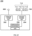
- the communication apparatus 200 includes a communication unit 202, an antenna control unit 204, and a surrounding environment identification unit 206.
- the communication unit 202 performs communication using the antenna 600 and the antenna unit 700.
- the communication unit 202 may communicate with a control apparatus of the vehicle 100 mounted with the communication apparatus 200.
- the control apparatus of the vehicle 100 may include a car navigation system.
- the plurality of antennas 712 and the plurality of antennas 714 are arranged so as to enhance a diversity effect in accordance with the surrounding environment of the vehicle 100 and the communication partner of the time and to contribute to improvement of a reception quality.
- the surrounding environment identification unit 2206 identifies a surrounding environment of the vehicle 2100 mounted with the communication apparatus 2200 and a vehicle mounted with a communication partner of the communication apparatus 2200.
- the surrounding environment identification unit 2206 identifies the surrounding environment, for example, by using map information of a position at which the vehicle 2100 is travelling which is obtained from the control apparatus of the vehicle 2100.
- the surrounding environment identification unit 2206 identifies the surrounding environment, for example, by using a captured image of surroundings of the vehicle 2100 which is obtained from the control apparatus of the vehicle 2100.
- the surrounding environment identification unit 2206 may identify presence of a surrounding reflector. Examples of a reflector include a side wall, architectural structures such as a building and a house, another vehicle, a tunnel, and the like.
- Fig. 31 and Fig. 32 schematically show another example of a system 2010.
- the system 2010 includes a communication apparatus 2200, an antenna unit 2800, and a movable object mounted with the communication apparatus 2200 and the antenna unit 2800.
- the vehicle 2100 in Fig. 31 and Fig. 32 is an example of the movable object.
- Fig. 31 schematically shows a front of the vehicle 2100
- Fig. 32 schematically shows a back of the vehicle 2100.
- the antenna unit 2800 is arranged on the front of the vehicle 2100.
- An antenna 2900 is arranged on the back of the vehicle 2100.
- FIG. 33 schematically shows an example of a hardware configuration of a computer 1200 functioning as a communication apparatus 200.
- a program installed in the computer 1200 can cause the computer 1200 to function as one or more "units" of an apparatus according to the present embodiment, or cause the computer 1200 to perform operations associated with the apparatus or perform one or more "units” thereof according to the present embodiment, and/or cause the computer 1200 to perform the process according to the present embodiment or perform the steps of the process.
- Such a program may be executed by a CPU 1212 to cause the computer 1200 to perform particular operations associated with some or all of the blocks in the flowcharts and block diagrams described in the specification.
- the communication interface 1222 communicates with another electronic device via a network.
- the storage apparatus 1224 stores a program and data used by the CPU 1212 in the computer 1200.
- the DVD drive reads the programs or the data from the DVD-ROM or the like, and provides the storage apparatus 1224 with the programs or the data.
- the IC card drive reads programs and data from an IC card and/or writes programs and data into the IC card.
- the ROM 1230 stores therein a boot program or the like executed by the computer 1200 at the time of activation, and/or a program depending on the hardware of the computer 1200.
- the input/output chip 1240 may also connect various input/output units via a USB port, a parallel port, a serial port, a keyboard port, a mouse port, or the like to the input/output controller 1220.
- a program is provided by a computer readable storage medium such as the DVD-ROM or the IC card.
- the program is read from the computer readable storage medium, installed into the storage apparatus 1224, RAM 1214, or ROM 1230, which are also examples of a computer readable storage medium, and executed by the CPU 1212.
- Information processing written in these programs is read by the computer 1200, and provides cooperation between the programs and the various types of hardware resources described above.
- An apparatus or method may be composed of by realizing the operation or processing of information in accordance with the usage of the computer 1200.
- the CPU 1212 may execute a communication program loaded in the RAM 1214 and instruct the communication interface 1222 to perform communication processing on a basis of a processing written in the communication program.
- the communication interface 1222 under control of the CPU 1212, reads transmission data stored on a transmission buffer region provided in a recording medium such as the RAM 1214, the storage apparatus 1224, the DVD-ROM, or the IC card, and transmits the read transmission data to a network or writes reception data received from a network to a reception buffer region or the like provided on the recording medium.
- the CPU 1212 may cause all or a necessary portion of a file or a database to be read into the RAM 1214, the file or the database having been stored in an external recording medium such as the storage apparatus 1224, the DVD drive (DVD-ROM), the IC card, etc., and perform various types of processing on the data on the RAM 1214.
- the CPU 1212 may write the processed data back in the external recording medium.
- the CPU 1212 may execute, on the data read from the RAM 1214, various types of processing including various types of operations, information processing, conditional judgement, conditional branching, unconditional branching, information search/replacement, or the like described throughout the present disclosure and specified by instruction sequences of the programs, to write the results back to the RAM 1214.
- the CPU 1212 may search for information in a file, a database, or the like in the recording medium.
- the CPU 1212 may search for an entry whose attribute value of the first attribute matches a specified condition, from among the plurality of entries, and read the attribute value of the second attribute stored in the entry, thereby obtaining the attribute value of the second attribute associated with the first attribute satisfying a predetermined condition.
- the above-described program or software modules may be stored in the computer readable storage medium on or near the computer 1200.
- a recording medium such as a hard disk or a RAM provided in a server system connected to a dedicated communication network or the Internet can be used as the computer readable storage medium, thereby providing the program to the computer 1200 via the network.
- Blocks in flowcharts and block diagrams in the present embodiments may represent steps of processes in which operations are performed or "units" of apparatuses responsible for performing operations.
- a specific step and "unit” may be implemented by dedicated circuit, programmable circuit supplied along with a computer readable instruction stored on a computer readable storage medium, and/or a processor supplied along with the computer readable instruction stored on the computer readable storage medium.
- the dedicated circuit may include a digital and/or analog hardware circuit, or may include an integrated circuit (IC) and/or a discrete circuit.
- the programmable circuit may include, for example, a reconfigurable hardware circuit including logical AND, logical OR, logical XOR, logical NAND, logical NOR, and another logical operation, and a flip-flop, a register, and a memory element, such as a field programmable gate array (FPGA) and a programmable logic array (PLA).
- a reconfigurable hardware circuit including logical AND, logical OR, logical XOR, logical NAND, logical NOR, and another logical operation
- FPGA field programmable gate array
- PDA programmable logic array
- the computer readable storage medium may include a floppy (registered trademark) disk, a diskette, a hard disk, a random access memory (RAM), a read only memory (ROM), an erasable programmable read only memory (EPROM or flash memory), an electrically erasable programmable read only memory (EEPROM), a static random access memory (SRAM), a compact disk read only memory (CD-ROM), a digital versatile disk (DVD), a Blu-ray (registered trademark) disk, a memory stick, an integrated circuit card, or the like.
- a floppy (registered trademark) disk a diskette, a hard disk, a random access memory (RAM), a read only memory (ROM), an erasable programmable read only memory (EPROM or flash memory), an electrically erasable programmable read only memory (EEPROM), a static random access memory (SRAM), a compact disk read only memory (CD-ROM), a digital versatile disk (DVD), a Blu-ray (registere
- the computer readable instruction may include an assembler instruction, an instruction-set-architecture (ISA) instruction, a machine instruction, a machine dependent instruction, a microcode, a firmware instruction, state-setting data, or either of source code or object code written in any combination of one or more programming languages including an object-oriented programming language such as Smalltalk (registered trademark), JAVA (registered trademark), and C++, and a conventional procedural programming language such as a "C" programming language or a similar programming language.
- ISA instruction-set-architecture
- machine instruction e.g., JAVA (registered trademark), and C++
- a conventional procedural programming language such as a "C" programming language or a similar programming language.
- the computer readable instruction may be provided to a general purpose computer, a special purpose computer, or a processor or programmable circuit of another programmable data processing apparatus locally or via a local area network (LAN), a wide area network (WAN) such as the Internet or the like in order that the general purpose computer, the special purpose computer, or the processor or the programmable circuit of the another programmable data processing apparatus performs the computer readable instruction to provide means for performing operations specified by the flowchart or the block diagram.
- the processor include a computer processor, a processing unit, a microprocessor, a digital signal processor, a controller, a microcontroller, and the like.
Landscapes
- Engineering & Computer Science (AREA)
- Computer Networks & Wireless Communication (AREA)
- Signal Processing (AREA)
- Variable-Direction Aerials And Aerial Arrays (AREA)
- Mobile Radio Communication Systems (AREA)
Abstract
Description
- The present invention relates to an antenna apparatus, a system, a communication apparatus, and a program.
- Non-Patent
Documents Document 3 describes that antenna spacing for spatial diversity is based on non-line-of-sight communication and that it suffices to have a spacing of a half wavelength or more on a mobile station side and a spacing of 10 wavelengths or more on a base station side. -
- Non-Patent Document 1: Akihito Kato, Katsuyoshi Sato, Masayuki Fujise, "Technologies of Millimeter-wave Inter-vehicle Communications - Propagation Characteristics -", Review of the Communications Research Laboratory, vol.47, no.4, Dec. 2001
- Non-Patent Document 2: Akihito Kato, et al., "Propagation Characteristics of 60-GHz Millimeter Waves for ITS Inter-Vehicle Communications", IEICE TRANS. COMMUN., VOL. E84-B, NO. 9 SEPTEMBER 2001
- Non-Patent Document 3: Yoshio Karasawa, "Radiowave Propagation Fundamentals for Digital Mobile Communications" Corona Publishing Co., Ltd., First Print of Second Edition, Mar. 2016
- One embodiment of the present invention provides an antenna apparatus. The antenna apparatus may be mounted on a movable object. The antenna apparatus may include an antenna array including: a plurality of first antennas which are arranged by being shifted by a distance equivalent to an odd multiple of a half period of a maximum fluctuation period of a radio wave having a longest fluctuation period among a plurality of radio waves received from an antenna of a communication partner; and a plurality of second antennas which are respectively arranged by being shifted with respect to the plurality of first antennas by a distance equivalent to an odd multiple of a half period of a minimum fluctuation period of a radio wave having a shortest fluctuation period among the plurality of radio waves.
- The plurality of first antennas may be arranged by being shifted by the distance equivalent to the odd multiple of the half period of the maximum fluctuation period calculated from a minimum value for a distance between the antenna of the communication partner and a reflector. The plurality of second antennas may be respectively arranged by being shifted with respect to the plurality of first antennas by the distance equivalent to the odd multiple of the half period of the minimum fluctuation period calculated from respective distances between the antenna of the communication partner and two reflectors in an environment where the antenna apparatus and the communication partner are sandwiched between the two reflectors and from a number of at least one reflection. The plurality of first antennas may be arranged by being shifted in a lateral direction by the distance equivalent to the odd multiple of the half period of the maximum fluctuation period calculated from a minimum value for a distance between the antenna of the communication partner and a reflector in an environment where the antenna apparatus and the communication partner are sandwiched between two reflectors located in a lateral direction. The plurality of second antennas may be respectively arranged by being shifted in a lateral direction with respect to the plurality of first antennas by the distance equivalent to the odd multiple of the half period of the minimum fluctuation period calculated from respective distances between the antenna of the communication partner and two reflectors located in a lateral direction in an environment where the antenna apparatus and the communication partner are sandwiched between the two reflectors and from a number of at least one reflection. The antenna apparatus may be an antenna apparatus for a vehicle travelling on a road, the two reflectors may be side walls installed on the road, and respective distances between the antenna of the communication partner and the two reflectors may be distances corresponding to distances between the antenna of the communication partner and the two reflectors which are assumed when the communication partner travels on the road. The antenna apparatus may be an antenna apparatus for a vehicle travelling on a road, at least one of the two reflectors may be a side vehicle travelling on a side of the vehicle, and a distance between the antenna of the communication partner and the side vehicle may be a distance corresponding to the distance between the antenna of the communication partner and the side vehicle which is assumed when the side vehicle travels on a side of the communication partner.
- The plurality of first antennas may be arranged by being shifted in a longitudinal direction by the distance equivalent to the odd multiple of the half period of the maximum fluctuation period calculated from a minimum value for a distance between the antenna of the communication partner and a reflector in an environment where the antenna apparatus and the communication partner are sandwiched between two reflectors located in a longitudinal direction. The plurality of second antennas may be respectively arranged by being shifted in a longitudinal direction with respect to the plurality of first antennas by the distance equivalent to the odd multiple of the half period of the minimum fluctuation period calculated from respective distances between the antenna of the communication partner and two reflectors located in a longitudinal direction in an environment where the antenna apparatus and the communication partner are sandwiched between the two reflectors and from a number of at least one reflection. The antenna apparatus may be an antenna apparatus for a vehicle travelling on a road, one of the two reflectors may be a road, and another of the two reflectors may be a roof of a tunnel, and a distance between the antenna of the communication partner and the road may be a distance corresponding to the distance between the antenna of the communication partner and the road which is assumed when the communication partner travels on the road, and a distance between the antenna of the communication partner and the roof may be a distance corresponding to the distance between the antenna of the communication partner and the roof which is assumed when the communication partner travels in the tunnel.
- The plurality of first antennas may be arranged by being shifted in a lateral direction by the distance equivalent to the odd multiple of the half period of the maximum fluctuation period calculated from a minimum value for a distance between the antenna of the communication partner and a reflector in an environment where a plurality of reflectors are located in a lateral direction of the antenna apparatus and the communication partner, and the plurality of second antennas may be respectively arranged by being shifted in a lateral direction with respect to the plurality of first antennas by the distance equivalent to the odd multiple of the half period of the minimum fluctuation period calculated from respective distances between the antenna of the communication partner and the plurality of reflectors in an environment where the plurality of reflectors are located in a lateral direction of the antenna apparatus and the communication partner.
- The plurality of first antennas may include two first antennas which are arranged by being shifted in a lateral direction by the distance equivalent to the odd multiple of the half period of the maximum fluctuation period calculated from a minimum value for distances between the antenna of the communication partner and two reflectors in a lateral direction in an environment where the antenna apparatus and the communication partner are sandwiched between the two reflectors in the lateral direction, the plurality of second antennas may include two second antennas which are respectively arranged by being shifted in a lateral direction with respect to the two first antennas by the distance equivalent to the odd multiple of the half period of the minimum fluctuation period calculated from respective distances between the antenna of the communication partner and the two reflectors in the lateral direction in the environment where the antenna apparatus and a communication partner are sandwiched between the two reflectors in the lateral direction and from a number of at least one reflection, and the antenna apparatus may include: two third antennas which are respectively arranged by being shifted in a longitudinal direction with respect to the two first antennas by the distance equivalent to the odd multiple of the half period of the maximum fluctuation period calculated from a minimum value for a distance between the antenna of the communication partner and a reflector in an environment where the antenna apparatus and the communication partner are sandwiched between two reflectors in a longitudinal direction; four fourth antennas which are respectively arranged by being shifted in a longitudinal direction with respect to the two first antennas and the two third antennas by the distance equivalent to the odd multiple of the half period of the minimum fluctuation period calculated from respective distances between the antenna of the communication partner and the two reflectors in the longitudinal direction in the environment where the antenna apparatus and a communication partner are sandwiched between the two reflectors in the longitudinal direction and from a number of at least one reflection; two fifth antennas which are respectively arranged by being shifted in a longitudinal direction with respect to the two second antennas by the distance equivalent to the odd multiple of the half period of the maximum fluctuation period calculated from the minimum value for the distance between the antenna of the communication partner and the reflector in the environment where the antenna apparatus and the communication partner are sandwiched between two reflectors in a longitudinal direction; and four sixth antennas which are respectively arranged by being shifted in a longitudinal direction with respect to the two second antennas and the two fifth antennas by the distance equivalent to the odd multiple of the half period of the minimum fluctuation period calculated from the respective distances between the antenna of the communication partner and the two reflectors in the longitudinal direction in the environment where the antenna apparatus and a communication partner are sandwiched between the two reflectors in the longitudinal direction and from a number of at least one reflection. The plurality of first antennas may include two first antennas which are arranged by being shifted in a lateral direction by the distance equivalent to the odd multiple of the half period of the maximum fluctuation period calculated from a minimum value for distances between the antenna of the communication partner and two reflectors in a lateral direction in an environment where the antenna apparatus and the communication partner are sandwiched between the two reflectors in the lateral direction and two reflectors in a longitudinal direction and which are arranged by being shifted in a longitudinal direction by the distance equivalent to the odd multiple of the half period of the maximum fluctuation period calculated from a minimum value for distances between the antenna of the communication partner and the two reflectors in the longitudinal direction, and the plurality of second antennas may include two second antennas which are respectively arranged by being shifted in a lateral direction with respect to the two first antennas by the distance equivalent to the odd multiple of the half period of the minimum fluctuation period calculated from respective distances between the antenna of the communication partner and two reflectors in a lateral direction in the environment where the antenna apparatus and the communication partner are sandwiched between the two reflectors in the lateral direction and two reflectors in a longitudinal direction and from a number of at least one reflection and which are respectively arranged by being shifted in a longitudinal direction with respect to the two first antennas by the distance equivalent to the odd multiple of the half period of the minimum fluctuation period calculated from respective distances between the antenna of the communication partner and the two reflectors in the longitudinal direction and from a number of at least one reflection.
- One embodiment of the present invention provides an antenna apparatus. The antenna apparatus may be mounted on a movable object. The antenna apparatus may include an antenna array including: a plurality of first antennas which are arranged by being shifted by a distance equivalent to an odd multiple of a half period of a maximum fluctuation period of a radio wave having a longest fluctuation period among a plurality of radio waves transmitted by the antenna apparatus and received by a communication partner; and a plurality of second antennas which are respectively arranged by being shifted with respect to the plurality of first antennas by a distance equivalent to an odd multiple of a half period of a minimum fluctuation period of a radio wave having a shortest fluctuation period among the plurality of radio waves.
- One embodiment of the present invention provides a system including the antenna apparatus and the movable object.
- One embodiment of the present invention provides a communication apparatus. The communication apparatus may be mounted on a movable object. The communication apparatus may include: an antenna array including a plurality of first antennas and a plurality of second antennas. The communication apparatus may include a surrounding environment identification unit which identifies a surrounding environment of the movable object mounted with the communication apparatus and a movable object mounted with a communication partner of the communication apparatus. The communication apparatus may include an antenna control unit which controls positions of the plurality of first antennas and the plurality of second antennas such that the plurality of first antennas are shifted by a distance equivalent to an odd multiple of a half period of a maximum fluctuation period of a radio wave having a longest fluctuation period among a plurality of radio waves received from an antenna of the communication partner by an antenna apparatus and that the plurality of second antennas are respectively shifted with respect to the plurality of first antennas by a distance equivalent to an odd multiple of a half period of a minimum fluctuation period of a radio wave having a shortest fluctuation period among the plurality of radio waves, on a basis of a result of identification by the surrounding environment identification unit.
- One embodiment of the present invention provides a communication apparatus. The communication apparatus may be mounted on a movable object. The communication apparatus may include: an antenna array including a plurality of first antennas and a plurality of second antennas. The communication apparatus may include a surrounding environment identification unit which identifies a surrounding environment of the movable object mounted with the communication apparatus and a movable object mounted with a communication partner of the communication apparatus. The communication apparatus may include an antenna control unit which controls positions of the plurality of first antennas and the plurality of second antennas such that the plurality of first antennas are shifted by a distance equivalent to an odd multiple of a half period of a maximum fluctuation period of a radio wave having a longest fluctuation period among a plurality of radio waves transmitted by an antenna apparatus and received by an antenna of the communication partner and that the plurality of second antennas are respectively shifted with respect to the plurality of first antennas by a distance equivalent to an odd multiple of a half period of a minimum fluctuation period of a radio wave having a shortest fluctuation period among the plurality of radio waves, on a basis of a result of identification by the surrounding environment identification unit.
- One embodiment of the present invention provides a program that causes a computer to function as the communication apparatus.
- One embodiment of the present invention provides an antenna apparatus. The antenna apparatus may be mounted on a movable object. The antenna apparatus may include an antenna array having a plurality of reception antennas. The plurality of reception antennas may be arranged by being shifted by a distance equivalent to an odd multiple of a half period of a fluctuation period of each horizontal and vertical component, assuming that a difference for the horizontal component and the vertical component between a plurality of regular reflection positions on a reflector between a transmission antenna of a communication partner and a first reception antenna of the plurality of reception antennas, and a position of the transmission antenna, is a distance for the horizontal component and the vertical component between the transmission antenna and the reflector, and using a value in a region where a fluctuation period is stable.
- The reflector may be a tunnel inner wall, and the regular reflection positions may be calculated on a basis of dimensions of any tunnel of a plurality of tunnels. The reflector may be a tunnel inner wall, and the regular reflection positions may be calculated on a basis of an average value for dimensions of a plurality of tunnels. The movable object may be a vehicle, the reflector in a horizontal direction may be a tunnel inner wall, the reflector in a vertical direction may be a road surface, and the plurality of reception antennas may be arranged by being shifted by a distance equivalent to an odd multiple of a half period of a fluctuation period of each horizontal and vertical component, assuming that a difference for each horizontal component between a plurality of regular reflection positions on a tunnel inner wall between the transmission antenna of the communication partner and the first reception antenna, and the position of the transmission antenna, is a distance for each component between the transmission antenna and the tunnel inner wall in a horizontal direction, assuming that a difference for each vertical component between the transmission antenna of the communication partner and a road surface is a distance for each component between the transmission antenna and the road surface in a vertical direction, and using a value in a region where a fluctuation period is stable. The movable object may be a vehicle, the reflector in a horizontal direction may be another vehicle located on a side of the movable object, the reflector in a vertical direction may be a tunnel inner wall, and the plurality of reception antennas may be arranged by being shifted by a distance equivalent to an odd multiple of a half period of a fluctuation period of each horizontal and vertical component, assuming that a difference for each horizontal component between the transmission antenna of the communication partner and the another vehicle is a distance for each component between the transmission antenna and the another vehicle in a horizontal direction, assuming that a difference for each vertical component between a plurality of regular reflection positions on a tunnel inner wall between the transmission antenna of the communication partner and the first reception antenna, and the position of the transmission antenna, is a distance for each component between the transmission antenna and the tunnel inner wall, and using a value in a region where a fluctuation period is stable.
- The plurality of reception antennas may be arranged by being shifted by a distance equivalent to an odd multiple of a half period of a fluctuation period of each horizontal and vertical component, assuming that the difference for the horizontal component and the vertical component between the plurality of regular reflection positions on the reflector between the transmission antenna of the communication partner and the first reception antenna, and the position of the transmission antenna, is the distance for the horizontal component and the vertical component between the transmission antenna and the reflector, and using a mode value of the horizontal component and the vertical component. The plurality of reception antennas may be arranged by being shifted by a distance equivalent to an odd multiple of a half period of a fluctuation period of each horizontal and vertical component, assuming that the difference for the horizontal component and the vertical component between the plurality of regular reflection positions on the reflector between the transmission antenna of the communication partner and the first reception antenna, and the position of the transmission antenna, is the distance for the horizontal component and the vertical component between the transmission antenna and the reflector, and using a median value of the horizontal component and the vertical component. The plurality of reception antennas may be arranged by being shifted by a distance equivalent to an odd multiple of a half period of a fluctuation period of each horizontal and vertical component ((2j + 1)λd/2|Xref0 - XTX0|, (2k + 1)λd/2|Yref0 - YTX0|), assuming that the difference for the horizontal component and the vertical component between the plurality of regular reflection positions on the reflector between the transmission antenna of the communication partner and the first reception antenna (Xrefi, Yrefi), and the position of the transmission antenna (XTX0, YTX0), is the distance for the horizontal component and the vertical component between the transmission antenna and the reflector (|Xrefi - XTX0|, |Yrefi - YTX0|), and using the value in the region where the fluctuation period calculated using a distance between the movable object and the communication partner as well as a working frequency (λd/2|Xrefi - XTX0|, λd/2/Yrefi - YTX0|) is stable (λd/2|Xref0 - XTX0|, λd/2|Yref0 - YTX0|).
- One embodiment of the present invention provides an antenna apparatus. The antenna apparatus may be mounted on a movable object. The antenna apparatus may include an antenna array having a plurality of transmission antennas. The plurality of transmission antennas may be arranged by being shifted by a distance equivalent to an odd multiple of a half period of a fluctuation period of each horizontal and vertical component, assuming that a difference for the horizontal component and the vertical component between a plurality of regular reflection positions on a reflector between a reception antenna of a communication partner and a first transmission antenna of the plurality of transmission antennas, and a position of the reception antenna, is a distance for the horizontal component and the vertical component between the reception antenna and the reflector, and using a value in a region where a fluctuation period is stable.
- One embodiment of the present invention provides a system including the antenna apparatus and the movable object.
- One embodiment of the present invention provides a communication apparatus. The communication apparatus may be mounted on a movable object. The communication apparatus may include an antenna array having a plurality of reception antennas. The communication apparatus may include a surrounding environment identification unit which identifies a surrounding environment of the movable object mounted with the communication apparatus and a movable object mounted with a communication partner of the communication apparatus, the surrounding environment identification unit identifying a reflector between the movable object and the communication partner. The communication apparatus may include an antenna control unit which controls positions of the plurality of reception antennas such that they are arranged by being shifted by a distance equivalent to an odd multiple of a half period of a fluctuation period of each horizontal and vertical component, assuming that a difference for the horizontal component and the vertical component between a plurality of regular reflection positions on the reflector and a position of the transmission antenna, is a distance for the horizontal component and the vertical component between the transmission antenna and the reflector, and using a value in a region where a fluctuation period is stable.
- One embodiment of the present invention provides a communication apparatus. The communication apparatus may be mounted on a movable object. The communication apparatus may include an antenna array having a plurality of transmission antennas. The communication apparatus may include a surrounding environment identification unit which identifies a surrounding environment of the movable object mounted with the communication apparatus and a movable object mounted with a communication partner of the communication apparatus, the surrounding environment identification unit identifying a reflector between the movable object and the communication partner. The communication apparatus may include an antenna control unit which controls positions of the plurality of transmission antennas such that they are arranged by being shifted by a distance equivalent to an odd multiple of a half period of a fluctuation period of each horizontal and vertical component, assuming that a difference for the horizontal component and the vertical component between a plurality of regular reflection positions on the reflector and a position of the reception antenna, is a distance for the horizontal component and the vertical component between the reception antenna and the reflector, and using a value in a region where a fluctuation period is stable.
- The summary clause does not necessarily describe all necessary features of the embodiments of the present invention. In addition, the invention may also be a sub-combination of the features described above.
-
-
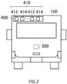
Fig. 1 schematically shows an example of asystem 10. -
Fig. 2 schematically shows an example of asystem 10. -
Fig. 3 schematically shows an example of an environment of anantenna 412 of an own vehicle and anantenna 300 of a communication partner. -
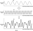
Fig. 4 schematically shows an example of a longperiod level fluctuation 502, a shortperiod level fluctuation 504, and a combinedwave level fluctuation 506. -
Fig. 5 is an explanatory drawing for illustrating a reception level of a combinedwave level fluctuation 506 for a case whereantennas 412 are arranged in accordance with a half period of a longperiod level fluctuation 502. -
Fig. 6 schematically shows an example of a configuration of anantenna array 410. -
Fig. 7 schematically shows another example of a configuration of anantenna array 410. -
Fig. 8 schematically shows another example of a configuration of anantenna array 410. -
Fig. 9 schematically shows another example of a configuration of anantenna array 410. -
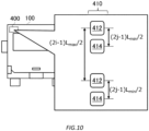
Fig. 10 schematically shows another example of a configuration of anantenna array 410. -
Fig. 11 schematically shows another example of a configuration of anantenna array 410. -
Fig. 12 schematically shows another example of a configuration of anantenna array 410. -
Fig. 13 schematically shows an example of an environment of anantenna unit 400 of an own vehicle and anantenna 300 of a communication partner. -
Fig. 14 schematically shows another example of acommunication apparatus 200. -
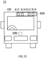
Fig. 15 schematically shows another example of asystem 10. -
Fig. 16 schematically shows another example of asystem 10. -
Fig. 17 schematically shows an example of asystem 2010. -
Fig. 18 schematically shows an example of asystem 2010. -
Fig. 19 is an explanatory drawing for illustrating a distance between transmission antenna and reflector for a case where a reflector is a road surface, a side reflector, or the like. -
Fig. 20 is an explanatory drawing for illustrating a distance between transmission antenna and reflector for a case where a reflector is a tunnel. -
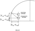
Fig. 21 is an explanatory drawing for illustrating arrangement of a plurality ofantennas 2412 in anantenna unit 2400. -
Fig. 22 is an explanatory drawing for illustrating arrangement of a plurality ofantennas 2412 in anantenna unit 2400. -
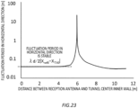
Fig. 23 is an explanatory drawing for illustrating a relationship between a distance between reception antenna and tunnel center inner wall, and a fluctuation period of a radio wave in a horizontal direction. -
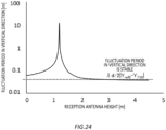
Fig. 24 is an explanatory drawing for illustrating a relationship between a reception antenna height and a fluctuation period of a radio wave in a vertical direction. -
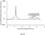
Fig. 25 is an explanatory drawing for illustrating a relationship between a reception antenna height and a fluctuation period of a radio wave in a vertical direction. -
Fig. 26 is an explanatory drawing for illustrating a method for determining a regular reflection point and a mode value. -
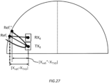
Fig. 27 is an explanatory drawing for illustrating a distance between transmission antenna and reflector for a case where a Fresnel zone is considered. -
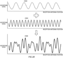
Fig. 28 schematically shows an example of a longperiod level fluctuation 2502, a shortperiod level fluctuation 2504, and a combinedwave level fluctuation 2506. -
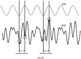
Fig. 29 is an explanatory drawing for illustrating a reception level of a combinedwave level fluctuation 2506 for a case whereantennas 2412 are arranged in accordance with a half period of a longperiod level fluctuation 2502. -
Fig. 30 schematically shows another example of acommunication apparatus 2200. -
Fig. 31 schematically shows another example of asystem 2010. -
Fig. 32 schematically shows another example of asystem 2010. -
Fig. 33 schematically shows an example of a hardware configuration of acomputer 1200 which functions as acommunication apparatus 2200. - Although it is shown that spatial diversity is effective in vehicle-to-vehicle communication (Non-Patent Document 1), there is no mention of an optimal antenna array configuration method. It is described that antenna spacing for spatial diversity in mobile communication is based on non-line-of-sight communication in general and that it suffices to have a spacing of a half wavelength or more on a mobile station side and a spacing of 10 wavelengths or more on a base station side (Non-Patent Document 2).
- The vehicle-to-vehicle communication is line-of-sight communication, but in a case of the line-of-sight communication, a level may periodically fluctuate in vertical and horizontal directions within a flat surface perpendicular to a road surface where a reception point is located, due to interference of a road surface reflected wave and a side reflected wave. It is necessary, in considering diversity, to optimize an antenna array configuration in consideration of periodicity of this fluctuation, but in an environment of being sandwiched, such as a space between a road surface and a roof surface of a bridge or the like, or a space between left and right side reflectors, a plurality of reflected waves are received together, so all antennas used for the diversity may become a null point. Therefore, it is necessary to take this into consideration. A
system 10 according to the present embodiment has an antenna array configuration suitable for the line-of-sight communication such as the vehicle-to-vehicle communication. - Hereinafter, the present invention will be described through embodiments of the invention, but the following embodiments do not limit the invention according to claims. In addition, not all of the combinations of features described in the embodiments are essential to the solution of the invention.
-
Fig. 1 andFig. 2 schematically show an example of asystem 10 according to the present embodiment. Thesystem 10 includes acommunication apparatus 200, anantenna unit 400, and a movable object mounted with thecommunication apparatus 200 and theantenna unit 400. Avehicle 100 inFig. 1 andFig. 2 is an example of the movable object. Thevehicle 100 may be an automobile. -
Fig. 1 schematically shows a front of thevehicle 100, andFig. 2 schematically shows a back of thevehicle 100. Anantenna 300 is arranged on the front of thevehicle 100. Theantenna unit 400 is arranged on the back of thevehicle 100. - The
antenna unit 400 includes an antenna array.Fig. 2 illustrates a case where theantenna unit 400 has anantenna array 410 composed of a plurality ofantennas 412 and a plurality ofantennas 414. Theantenna unit 400 may be an example of an antenna apparatus. Thecommunication apparatus 200 including theantenna unit 400 may be an example of the antenna apparatus. - The
communication apparatus 200 uses theantenna 300 and theantenna unit 400 to communicate with acommunication apparatus 200 mounted on anothervehicle 100 which is different from the vehicle 100 (which may be described as an own vehicle) mounted with thecommunication apparatus 200. For example, thecommunication apparatus 200 uses theantenna 300 to transmit data to anothervehicle 100 travelling ahead of the own vehicle, and uses theantenna unit 400 to receive data from anothervehicle 100 travelling behind the own vehicle. Theantenna 300 may be a transmission antenna, and theantenna unit 400 may be a reception antenna unit. -
Fig. 3 schematically shows an example of an environment of anantenna 412 of an own vehicle and anantenna 300 of a communication partner. In the example shown inFig. 3 , the own vehicle and the communication partner are located in an environment where they are sandwiched between awall 22 and awall 24. - In the present example, the
antenna 412 receives adirect wave 32, a reflectedwave 34, and a reflectedwave 36. Here, description will be made assuming that a transmission/reception distance between theantenna 412 and theantenna 300 is d, a distance between transmission antenna and left reflector as a distance between theantenna 300 and thewall 22 is WITX, a distance between transmission antenna and right reflector as a distance between theantenna 300 and thewall 24 is WrTX, a distance between reception antenna and left reflector as a distance between theantenna 412 and thewall 22 is WlRX, a distance between reception antenna and right reflector as a distance between theantenna 412 and thewall 24 is WrRX, and a distance between reflectors as a distance between thewall 22 and thewall 24 is D. - A propagation distance rd of the direct wave can be calculated according to
Expression 1 described below.
- hTX represents a height of the
antenna 300 from a ground, and hRX represents a height of theantenna 412 from the ground. - A radio wave distance rs of the reflected wave can be calculated according to
Expression 2 described below.
- When the reflected wave enters to the right and the number of reflections n is an odd number, α = WrTX and β = WrRX. When the reflected wave enters to the right and the number of reflections n is an even number, α = WrTX and β = WlRX. When the reflected wave enters to the left and the number of reflections n is an odd number, α = WlTX and β = WlRX. When the reflected wave enters to the left and the number of reflections n is an even number, α = WlTX and β = WrRX.
- A path difference Δrs between the direct wave and the reflected wave can be calculated according to
Expression 3 described below.
- When
Expression 3 is approximated by a generalized binomial theorem, it can be expressed as inExpression 4 described below.
- When the reflected wave enters to the right and the number of reflections n is an odd number, a path difference Δrs1 can be expressed as in
Expression 5 described below.
- When the reflected wave enters to the right and the number of reflections n is an even number, a path difference Δrs2 can be expressed as in
Expression 6 described below.
- When the reflected wave enters to the left and the number of reflections n is an odd number, a path difference Δrs3 can be expressed as in
Expression 7 described below.
- When the reflected wave enters to the left and the number of reflections n is an even number, a path difference Δrs4 can be expressed as in
Expression 8 described below.
- When the path difference is converted to a phase difference, a first term of wrRX and wlRX becomes a fluctuation component and a second term thereof becomes a constant component, so a fluctuation period in a horizontal direction within a flat surface perpendicular to a road surface where a reception point is located can be expressed as in Expression 9 for Δrs1, as in
Expression 10 for Δrs2, as in Expression 11 for Δrs3, and as inExpression 12 for Δrs4.


-
Fig. 4 schematically shows an example of a longperiod level fluctuation 502, a shortperiod level fluctuation 504, and a combinedwave level fluctuation 506. The longperiod level fluctuation 502 indicates fluctuation in a reception level of a reflectedwave 34 with respect to a reception antenna position. The shortperiod level fluctuation 504 indicates fluctuation in a reception level of a reflectedwave 36 with respect to the reception antenna position. The combinedwave level fluctuation 506 indicates fluctuation in a reception level of a combined wave of the reflectedwave 34 and the reflectedwave 36 with respect to the reception antenna position. In an environment of being sandwiched between a plurality of reflectors as shown inFig. 3 , a plurality of reflected waves are received together as shown inFig. 4 . -
Fig. 5 is an explanatory drawing for illustrating a reception level of a combinedwave level fluctuation 506 for a case whereantennas 412 are arranged in accordance with a half period of a longperiod level fluctuation 502. When only a reflectedwave 34 is a radio wave to be received, as illustrated inFig. 5 , it is possible to prevent all theantennas 412 from simultaneously becoming a null point by arranging theantennas 412 in accordance with the half period of the longperiod level fluctuation 502. - However, when a reflected
wave 36 is received in addition to the reflectedwave 34, all the antennas used for diversity may become the null point, or if not the null point, the reception level may become very low as illustrated inFig. 5 . - An
antenna array 410 of anantenna unit 400 according to the present embodiment includes: a plurality ofantennas 412 which are arranged by being shifted by a distance equivalent to an odd multiple of a half period of a maximum fluctuation period of a radio wave having a longest fluctuation period among a plurality of radio waves received from anantenna 300 of a communication partner; and a plurality ofantennas 414 which are respectively arranged by being shifted with respect to the plurality ofantennas 412 by a distance equivalent to an odd multiple of a half period of a minimum fluctuation period of a radio wave having a shortest fluctuation period among the plurality of radio waves. Including the plurality ofantennas 414 in addition to the plurality ofantennas 412 can prevent the null point or a low reception level point from being generated in a case of including only the plurality ofantennas 412, and can reduce deterioration of a quality from a required quality. - For example, the plurality of
antennas 412 are arranged by being shifted by the distance equivalent to the odd multiple of the half period of the maximum fluctuation period calculated from a minimum value for a distance between theantenna 300 of the communication partner and a reflector. For example, in the example shown inFig. 3 , the minimum value for the distance between theantenna 300 of the communication partner and the reflector is WlTX. - For example, the plurality of
antennas 414 are respectively arranged by being shifted with respect to the plurality ofantennas 412 by the distance equivalent to the odd multiple of the half period of the minimum fluctuation period calculated from respective distances between theantenna 300 of the communication partner and two reflectors in an environment where an own vehicle and the communication partner are sandwiched between the two reflectors and from the number of reflections. For example, in the example shown inFig. 3 , they are arranged by being shifted by a distance equivalent to an odd multiple of a half period of a fluctuation period value which is the smallest of LS1, LS2 = LS4, and LS3. - The plurality of
antennas 412 and the plurality ofantennas 414 may be arranged, for example, at intervals determined based on a maximum fluctuation period and a minimum fluctuation period assumed in an environment where avehicle 100 is highly likely to be located. For example, for thevehicle 100 travelling on a highway relatively frequently, the intervals may be determined based on a maximum fluctuation period and a minimum fluctuation period for a case where reflection caused by side walls located on both sides is assumed. For example, for thevehicle 100 which travels in a residential area relatively frequently, the intervals may be determined based on a maximum fluctuation period and a minimum fluctuation period for a case where reflection caused by houses located on both sides is assumed. -
Fig. 6 schematically shows an example of a configuration of anantenna array 410. A plurality ofantennas 412 may be arranged by being shifted by a distance equivalent to an odd multiple of a half period of a maximum fluctuation period calculated from a minimum value for a distance between anantenna 300 of a communication partner and a reflector in an environment where avehicle 100 and the communication partner are sandwiched between two reflectors located in a lateral direction. A plurality ofantennas 414 may be respectively arranged by being shifted in a lateral direction with respect to the plurality ofantennas 412 by a distance equivalent to an odd multiple of a half period of a minimum fluctuation period calculated from respective distances between theantenna 300 of the communication partner and the two reflectors located in the lateral direction in the environment where thevehicle 100 and the communication partner are sandwiched between the two reflectors and from the number of reflections. The expression "arranged by being shifted in a lateral direction" may mean "arranged by being shifted in a horizontal direction". Anantenna 412 may be an example of a first antenna. Anantenna 414 may be an example of a second antenna. - For example, the plurality of
antennas 412 are arranged at an interval equivalent to an odd multiple of a half period of a maximum fluctuation period calculated from a minimum value for a distance between a main reflector and theantenna 300 of the communication partner, Lmax = (λd)/(2·[the distance to the main reflector]), that is, (2i - 1)Lmax/2 (i = 1, 2, ...). The distance to the main reflector may be a distance to a reflector having a shortest distance to theantenna 300 among a plurality of reflectors in an environment where thevehicle 100 is highly likely to be placed. WlTX in the example shown inFig. 3 corresponds to the distance to the main reflector.Fig. 6 illustrates a case where theantenna array 410 includes twoantennas 412. - For example, the plurality of
antennas 414 are arranged around theantenna 412 at an interval equivalent to an odd multiple of a half period of a minimum fluctuation period Lmin to be considered which is calculated from a distance between each reflector and theantenna 300 of the communication partner in the environment of being sandwiched between the two reflectors and from the number of reflections, that is, ±(2j - 1)Lmin/2 (j = 1, 2, ...). In the example shown inFig. 3 , WlTX and WrTx correspond to the distance between each reflector and theantenna 300 of the communication partner. Lmin may be a value which is the smallest of LS1, LS2 (LS4), and LS3 calculated according to Expression 9, Expression 10 (Expression 12), and Expression 11.Fig. 6 illustrates a case where theantenna array 410 includes twoantennas 414. - The two reflectors in the lateral direction may be, for example, side walls installed on a road. The respective distances between the
antenna 300 of the communication partner and the two reflectors may be distances corresponding to distances in a lateral direction between theantenna 300 of the communication partner and the two reflectors assumed when the communication partner travels on the road. The distances can be determined in advance by a legal distance requirement for the side walls installed on the road. For example, if it is legally determined that the side walls should be arranged at a position 3.5 m away from the road, the distances may be determined by 3.5 m, a position of thevehicle 100 on the road, and a position of an antenna on thevehicle 100. In addition, the distances can also be determined in advance through actual measurement at multiple locations. For example, the distances may be determined, for example, by actually measuring a distance between the antenna of thevehicle 100 and the reflector in an environment where thevehicle 100 travels and averaging values which have been actually measured. - The two reflectors in the lateral direction may be, for example, side vehicles which travel on a side of the
vehicle 100 and the communication partner. A distance between theantenna 300 of the communication partner and a side vehicle may be a distance corresponding to a distance in a lateral direction between theantenna 300 of the communication partner and the side vehicle assumed when the side vehicle travels on the side of the communication partner. The distance can be determined in advance, for example, by a road width or through the actual measurement at multiple locations. - It should be noted that a value according to an assumed environment may be set as the number of reflections n. For example, a value determined on a basis of a distance between a reflector present in the assumed environment and the
antenna 300 of the communication partner as well as a material of the reflector is set as the number of reflections n. As a specific example, when the assumed reflector is a side wall of the road, and the material is concrete, a reflected wave which has been reflected more than three times is expected to attenuate to the point that it does not affect a received radio wave, so 3 may be set as the number of reflections. For example, when the assumed reflector is the side wall of the road, but the material is an iron-like material which has less attenuation caused by a reflection than concrete like iron, a number greater than 3 may be set as the number of reflections n. For example, when the material of the assumed reflector is concrete, but it is present at a position farther than the side wall of the road, a number smaller than 3 may be set as the number of reflections n. - Although
Fig. 6 shows an example where both of the twoantennas 414 are arranged in a right direction of the twoantennas 412, a positional relationship between the twoantennas 412 and the twoantennas 414 is not limited thereto. -
Fig. 7 schematically shows another example of a configuration of anantenna array 410. In the example shown inFig. 7 , both of twoantennas 414 are arranged in a left direction of twoantennas 412. - Although
Fig. 6 andFig. 7 illustrate a case where the twoantennas 414 are arranged by being shifted in the same direction with respect to the twoantennas 412, the present invention is not limited thereto, and the twoantennas 414 may be arranged by being shifted in different directions with respect to the twoantennas 412. -
Fig. 8 schematically shows another example of a configuration of anantenna array 410. In the example shown inFig. 8 , one of twoantennas 414 is arranged on a left side of aleft antenna 412 of twoantennas 412, and another of the twoantennas 414 is arranged on a right side of aright antenna 412 of the twoantennas 412. -
Fig. 9 schematically shows another example of a configuration of anantenna array 410. In the example shown inFig. 9 , one of twoantennas 414 is arranged on a right side of aleft antenna 412 of twoantennas 412, and another of the twoantennas 414 is arranged on a left side of aright antenna 412 of the twoantennas 412. - Although
Fig. 6 to Fig. 9 illustrate a case where the twoantennas 412 and the twoantennas 414 are arranged by being shifted in a lateral direction, the present invention is not limited thereto. The twoantennas 412 and the twoantennas 414 may be arranged by being shifted in a longitudinal direction when an environment is assumed in which they are sandwiched between two reflectors in a longitudinal direction such as a road surface and a roof, or the like. The expression "arranged by being shifted in a longitudinal direction" may mean "arranged by being shifted in a height direction". -
Fig. 10 schematically shows another example of a configuration of anantenna array 410. A plurality ofantennas 412 may be arranged by being shifted in a longitudinal direction by a distance equivalent to an odd multiple of a half period of a maximum fluctuation period calculated from a minimum value for a distance between anantenna 300 of a communication partner and a reflector in an environment where avehicle 100 and the communication partner are sandwiched between two reflectors located in a longitudinal direction. A plurality ofantennas 414 may be respectively arranged by being shifted in a longitudinal direction with respect to the plurality ofantennas 412 by a distance equivalent to an odd multiple of a half period of a minimum fluctuation period calculated from respective distances between theantenna 300 of the communication partner and the two reflectors in the longitudinal direction in the environment where thevehicle 100 and the communication partner are sandwiched between the two reflectors located in the longitudinal direction and from the number of reflections. - For example, one of the two reflectors may be a road, and another of the two reflectors may be a roof of a tunnel. A distance between the
antenna 300 of the communication partner and the road may be a distance corresponding to the distance between theantenna 300 of the communication partner and the road assumed when the communication partner travels on the road. The distance can be determined by an installation height of theantenna 300. - A distance between the
antenna 300 of the communication partner and the roof may be a distance corresponding to the distance between theantenna 300 of the communication partner and the roof assumed when the communication partner travels in the tunnel. The distance can be determined by the installation height of theantenna 300 and a height of a roof surface of the tunnel. - In the example shown in
Fig. 10 , the plurality ofantennas 412 are arranged by being shifted in a longitudinal direction at an interval of (2i - 1)Lmax/2. In addition, the plurality ofantennas 414 are arranged by being shifted in a downward direction with respect to theantennas 412 at an interval of ±(2j - 1)Lmin/2.Fig. 10 illustrates a case where theantenna array 410 includes twoantennas 412 and twoantennas 414. - Although
Fig. 10 illustrates a case where the twoantennas 414 are arranged by being shifted in a downward direction with respect to the twoantennas 412, the present invention is not limited thereto, and the twoantennas 414 may be arranged by being shifted in an upward direction with respect to the twoantennas 412. In addition, the twoantennas 414 may be arranged by being shifted in different directions with respect to the twoantennas 412 instead of being arranged by being shifted in the same direction with respect to the twoantennas 412. -
Fig. 11 schematically shows another example of a configuration of anantenna array 410.Fig. 11 schematically shows an example of the configuration of theantenna array 410 for a case where an environment is assumed in which avehicle 100 is sandwiched between two reflectors in a lateral direction and two reflectors in a longitudinal direction. - A plurality of
antennas 412 may include twoantennas 412 which are arranged by being shifted in a lateral direction by a distance equivalent to an odd multiple of a half period of a maximum fluctuation period calculated from a minimum value for distances between anantenna 300 of a communication partner and the two reflectors in the lateral direction and which are arranged by being shifted in a longitudinal direction by a distance equivalent to an odd multiple of a half period of a maximum fluctuation period calculated from a minimum value for distances between theantenna 300 of the communication partner and the two reflectors in the longitudinal direction. A plurality ofantennas 414 may include two second antennas which are respectively arranged by being shifted in a lateral direction with respect to the twoantennas 412 by a distance equivalent to an odd multiple of a half period of a minimum fluctuation period calculated from respective distances between theantenna 300 of the communication partner and the two reflectors in the lateral direction and from the number of reflections and which are respectively arranged by being shifted in a longitudinal direction with respect to the twoantennas 412 by a distance equivalent to an odd multiple of a half period of a minimum fluctuation period calculated from respective distances between theantenna 300 of the communication partner and the two reflectors in the longitudinal direction and from the number of reflections. - In the example shown in
Fig. 11 , the twoantennas 412 are arranged by being shifted in a lateral direction by a distance equivalent to an odd multiple of a half period of Lmax calculated from the minimum value for the distances between theantenna 300 of the communication partner and the two reflectors in the lateral direction, and are arranged by being shifted in a lateral direction by a distance equivalent to an odd multiple of a half period of Lmax calculated from the minimum value for the distances between theantenna 300 of the communication partner and the two reflectors in the longitudinal direction. In addition, twoantennas 414 are respectively arranged by being shifted in a lateral direction with respect to the twoantennas 412 by a distance equivalent to an odd multiple of a half period of a Lmin calculated from the respective distances between theantenna 300 of the communication partner and the two reflectors in the lateral direction and from the number of reflections, and are respectively arranged by being shifted in a longitudinal direction with respect to the twoantennas 412 by a distance equivalent to an odd multiple of a half period of a Lmin calculated from the respective distances between theantenna 300 of the communication partner and the two reflectors in the longitudinal direction and from the number of reflections. -
Fig. 12 schematically shows another example of a configuration of anantenna array 410.Fig. 12 schematically shows an example of a configuration of theantenna array 410 for a case where an environment is assumed in which avehicle 100 is sandwiched between two reflectors in a lateral direction and two reflectors in a longitudinal direction. Theantenna array 410 may include a plurality ofantennas 412, a plurality ofantennas 414, a plurality ofantennas 416, a plurality ofantennas 418, a plurality ofantennas 420, and a plurality ofantennas 422. - The plurality of
antennas 412 may include twoantennas 412 which are arranged by being shifted in a lateral direction by a distance equivalent to an odd multiple of a half period of a maximum fluctuation period calculated from a minimum value for distances between anantenna 300 of a communication partner and the two reflectors in the lateral direction. The plurality ofantennas 414 may include twoantennas 414 which are respectively arranged by being shifted in a lateral direction with respect to the twoantennas 412 by a distance equivalent to an odd multiple of a half period of a minimum fluctuation period calculated from respective distances between theantenna 300 of the communication partner and the two reflectors in the lateral direction and from the number of reflections. - The plurality of
antennas 416 may include twoantennas 416 which are respectively arranged by being shifted in a longitudinal direction with respect to the twoantennas 412 by the distance equivalent to the odd multiple of the half period of the maximum fluctuation period calculated from a minimum value for a distance between theantenna 300 of the communication partner and a reflector. Anantenna 416 may be an example of a third antenna. The plurality ofantennas 418 may include fourantennas 418 which are respectively arranged by being shifted in a longitudinal direction with respect to the twoantennas 412 and the twoantennas 416 by the distance equivalent to the odd multiple of the half period of the minimum fluctuation period calculated from respective distances between theantenna 300 of the communication partner and the two reflectors in the longitudinal direction and from the number of reflections. Anantenna 418 may be an example of a fourth antenna. - The plurality of
antennas 420 may include twoantennas 420 which are respectively arranged by being shifted in a longitudinal direction with respect to the twoantennas 414 by the distance equivalent to the odd multiple of the half period of the maximum fluctuation period calculated from the minimum value for the distance between theantenna 300 of the communication partner and the reflector. Anantenna 420 may be an example of a fifth antenna. The plurality ofantennas 422 may include fourantennas 422 which are respectively arranged by being shifted in a longitudinal direction with respect to the twoantennas 414 and the twoantennas 420 by the distance equivalent to the odd multiple of the half period of the minimum fluctuation period calculated from the respective distances between theantenna 300 of the communication partner and the two reflectors in the longitudinal direction and from the number of reflections. Anantenna 422 may be an example of a sixth antenna. - The
antenna array 410 illustrated inFig. 12 includes twoantennas 412, twoantennas 414, anantenna 416, and twoantennas 418. In the example shown inFig. 12 , the twoantennas 412 are arranged by being shifted in a lateral direction by a distance equivalent to an odd multiple of a half period of Lmax calculated from a minimum value for a distance between theantenna 300 of the communication partner and a reflector in a lateral direction. The twoantennas 414 are respectively arranged by being shifted in a lateral direction with respect to the twoantennas 412 by a distance equivalent to an odd multiple of a half period of Lmin calculated from the respective distances between theantenna 300 of the communication partner and the two reflectors in the lateral direction and from the number of reflections. - The
antenna 416 is arranged by being shifted in a longitudinal direction with respect to oneantenna 412 of the twoantennas 412 by the distance equivalent to the odd multiple of the half period of Lmax calculated from a minimum value for a distance between theantenna 300 of the communication partner and a reflector in a longitudinal direction. The twoantennas 418 are respectively arranged by being shifted in a longitudinal direction with respect to the oneantenna 412 and theantenna 416 by the distance equivalent to the odd multiple of the half period of Lmin calculated from the respective distances between theantenna 300 of the communication partner and the two reflectors in the longitudinal direction and from the number of reflections. -
Fig. 13 schematically shows an example of an environment of anantenna unit 400 of an own vehicle and anantenna 300 of a communication partner. Here, illustrated is an environment where a plurality of reflectors are located in the same direction with respect to the own vehicle and the communication partner, instead of an environment where the own vehicle and the communication partner are sandwiched between two reflectors. - A plurality of
antennas 412 included in theantenna unit 400 may be arranged by being shifted in a lateral direction by a distance equivalent to an odd multiple of a half period of a maximum fluctuation period calculated from a minimum value for a distance between theantenna 300 of the communication partner and a reflector. A plurality ofantennas 414 included in theantenna unit 400 may be respectively arranged by being shifted in a lateral direction with respect to the plurality ofantennas 412 by a distance equivalent to an odd multiple of a half period of a minimum fluctuation period calculated from respective distances between theantenna 300 of the communication partner and the plurality of reflectors. - The example shown in
Fig. 13 respectively illustrates aside vehicle 42, a side vehicle 44, a side vehicle 46, and aside vehicle 48, as an example of a first reflector, an example of a second reflector, an example of a third reflector, and an example of an mth reflector of m reflectors.Fig. 13 respectively shows a distance in a lateral direction between theantenna 300 and theside vehicle 42, a distance in a lateral direction between theantenna 300 and the side vehicle 44, a distance in a lateral direction between theantenna 300 and the side vehicle 46, and a distance in a lateral direction between theantenna 300 and theside vehicle 48, as w1, w2, w3, and wm. - When reflected waves arrive from the plurality of reflectors with different distances between the
antenna 300 which is a transmission antenna and a reflector, a level of a combined wave of a direct wave and each reflected wave periodically fluctuates in a lateral direction in theantenna unit 400, but each of fluctuation periods is Lm = (λd)/(2 × [a distance to a reflector m]. A minimum fluctuation period to be considered among these fluctuation periods is defined as Lmin. For example, L3 = (λd)/(2w3) with the side vehicle 46 may be defined as Lmin. - Although
Fig. 13 illustrates the side vehicles as examples of the plurality of reflectors located in the same direction, the reflectors are not limited thereto, and a side wall on only one side, a wall surface of a building, and the like may also serve as the reflectors. In addition, althoughFig. 13 illustrates an environment where the plurality of reflectors are located in the same direction with respect to the own vehicle and the communication partner, the present invention is not limited thereto, the plurality of reflectors may be located in different directions with respect to the own vehicle and the communication partner. -
Fig. 14 schematically shows another example of acommunication apparatus 200. Thecommunication apparatus 200 shown inFig. 14 performs communication using anantenna 600 and an antenna unit 700. Theantenna 600 may be arranged on a front of avehicle 100 similarly to anantenna 300, for example. The antenna unit 700 may be arranged on a back of thevehicle 100 similarly to anantenna unit 400, for example. Anantenna array 710 may include a plurality ofantennas 712 and a plurality ofantennas 714. - The
communication apparatus 200 includes acommunication unit 202, anantenna control unit 204, and a surroundingenvironment identification unit 206. Thecommunication unit 202 performs communication using theantenna 600 and the antenna unit 700. In addition, thecommunication unit 202 may communicate with a control apparatus of thevehicle 100 mounted with thecommunication apparatus 200. The control apparatus of thevehicle 100 may include a car navigation system. - The
antenna control unit 204 controls theantenna array 710. The plurality ofantennas 712 and the plurality ofantennas 714 may be configured such that their positions can be changed. The plurality ofantennas 712 and the plurality ofantennas 714 may be configured such that their positions can be changed in a lateral direction. The plurality ofantennas 712 and the plurality ofantennas 714 may be configured such that their positions can be changed in a longitudinal direction. The plurality ofantennas 712 and the plurality ofantennas 714 may be configured such that their positions can be changed in a lateral direction and a longitudinal direction. - The surrounding
environment identification unit 206 identifies a surrounding environment of thevehicle 100 mounted with thecommunication apparatus 200 and a vehicle mounted with a communication partner of thecommunication apparatus 200. The surroundingenvironment identification unit 206 identifies the surrounding environment, for example, by obtaining, from the control apparatus of thevehicle 100, map information of a position at which thevehicle 100 is travelling. The surroundingenvironment identification unit 206 may identify presence of a surrounding reflector. Examples of the reflector include a side wall, architectural structures such as a building and a house, a tunnel, and the like. - The
antenna control unit 204 may control positions of the plurality ofantennas 712 and the plurality ofantennas 714 on a basis of a result of identification by the surroundingenvironment identification unit 206. For example, on a basis of information on the reflector which has been identified, theantenna control unit 204 controls the positions of the plurality ofantennas 712 and the plurality ofantennas 714 such that the plurality ofantennas 412 are shifted by a distance equivalent to an odd multiple of a half period of a maximum fluctuation period of a radio wave having a longest fluctuation period among a plurality of radio waves received from theantenna 300 of the communication partner and that the plurality ofantennas 414 are respectively shifted with respect to the plurality ofantennas 412 by a distance equivalent to an odd multiple of a half period of a minimum fluctuation period of a radio wave having a shortest fluctuation period among the plurality of radio waves received from theantenna 300 of the communication partner. As a result, it is possible to arrange the plurality ofantennas 712 and the plurality ofantennas 714 so as to enhance a diversity effect in accordance with the surrounding environment of thevehicle 100 and the communication partner of the time and to contribute to improvement of a reception quality. - Although the above embodiment has been described using, as an example, a case where there is a single transmission antenna and a plurality of reception antennas, the present invention is not limited thereto, and transmission and reception may be interchanged. That is, the
vehicle 100 may include: an antenna unit for transmission having an antenna array including a plurality of antennas; and one antenna for reception. -
Fig. 15 andFig. 16 schematically show another example of asystem 10. Thesystem 10 includes acommunication apparatus 200, anantenna unit 800, and a movable object mounted with thecommunication apparatus 200 and theantenna unit 800. Avehicle 100 inFig. 15 andFig. 16 is an example of the movable object. -
Fig. 15 schematically shows a front of thevehicle 100, andFig. 16 schematically shows a back of thevehicle 100. Theantenna unit 800 is arranged on the front of thevehicle 100. Anantenna 900 is arranged on the back of thevehicle 100. - The
antenna unit 800 includes an antenna array 810.Fig. 15 illustrates a case where theantenna unit 800 has the antenna array 810 composed of a plurality ofantennas 812 and a plurality ofantennas 814. Theantenna unit 800 may be an example of an antenna apparatus. Thecommunication apparatus 200 including theantenna unit 800 may be an example of the antenna apparatus. - The
communication apparatus 200 uses theantenna 900 and theantenna unit 800 to communicate with acommunication apparatus 200 mounted on anothervehicle 100 which is different from the vehicle 100 (which may be described as an own vehicle) mounted with thecommunication apparatus 200. For example, thecommunication apparatus 200 uses theantenna unit 800 to transmit data to anothervehicle 100 travelling ahead of the own vehicle, and uses theantenna 900 to receive data from anothervehicle 100 travelling behind the own vehicle. Theantenna unit 800 may be a transmission antenna unit, and theantenna 900 may be a reception antenna. - The plurality of
antennas 812 may be arranged by being shifted by a distance equivalent to an odd multiple of a half period of a maximum fluctuation period of a radio wave having a longest fluctuation period among a plurality of radio waves transmitted by theantenna unit 800 and received by a communication partner. The plurality ofantennas 814 may be respectively arranged by being shifted with respect to the plurality ofantennas 812 by a distance equivalent to an odd multiple of a half period of a minimum fluctuation period of a radio wave having a shortest fluctuation period among the plurality of radio waves. This can prevent reception levels from simultaneously becoming null. - Although it is shown that spatial diversity is effective in vehicle-to-vehicle communication (Non-Patent Document 1), there is no mention of an optimal antenna array configuration method. It is described that antenna spacing for spatial diversity in mobile communication is based on non-line-of-sight communication in general and that it suffices to have a spacing of a half wavelength or more on a mobile station side and a spacing of 10 wavelengths or more on a base station side (Non-Patent Document 2). The vehicle-to-vehicle communication is line-of-sight communication, but in a case of the line-of-sight communication, a level may periodically fluctuate in a direction perpendicular to a reflection surface (in an upward direction in a case of a road surface) within a flat surface perpendicular to the road surface where a reception point is located, due to interference of reflected waves from reflectors such as the road surface and a side reflector (a side wall, a side vehicle, or the like). When a reflector is the road surface or the side reflector, a distance between transmission antenna and reflector is constant and a level fluctuation period is also constant regardless of a position at which the reception antenna is installed on a back of a preceding vehicle, so ensuring an optimal reception antenna spacing (an odd multiple of a half period of a fluctuation period) can avoid a null point where the level decreases and improve a communication quality.
- However, when the reflector is, for example, a tunnel, assuming that a distance between a transmission antenna position and a regular reflection position on a tunnel inner wall is the distance between transmission antenna and reflector, a cut surface is circular, so the distance between transmission antenna and reflector varies and the level fluctuation period also varies depending on the position at which the reception antenna is installed. Therefore, there has been a case where the optimal reception antenna spacing cannot be determined, all antenna positions used for diversity become the null point, and the communication quality deteriorates. The
system 10 according to the present embodiment has an antenna array configuration in which an environment, for example, in the tunnel is also considered. - Hereinafter, the present invention will be described through embodiments of the invention, but the following embodiments do not limit the invention according to claims. In addition, not all of the combinations of features described in the embodiments are essential to the solution of the invention.
-
Fig. 17 andFig. 18 schematically show an example of asystem 2010 according to the present embodiment. Thesystem 2010 includes acommunication apparatus 2200, anantenna unit 2400, and a movable object mounted with thecommunication apparatus 2200 and theantenna unit 2400. Avehicle 2100 inFig. 17 andFig. 18 is an example of the movable object. Thevehicle 2100 may be an automobile. -
Fig. 17 schematically shows a front of thevehicle 2100, andFig. 18 schematically shows a back of thevehicle 2100. Anantenna 2300 is arranged on the front of thevehicle 2100. Theantenna unit 2400 is arranged on the back of thevehicle 2100. - The
antenna unit 2400 includes an antenna array.Fig. 18 illustrates a case where theantenna unit 2400 has anantenna array 2410 composed of a plurality ofantennas 2412. Theantenna unit 2400 may be an example of an antenna apparatus. Thecommunication apparatus 2200 including theantenna unit 2400 may be an example of the antenna apparatus. - The
communication apparatus 2200 uses theantenna 2300 and theantenna unit 2400 to communicate with acommunication apparatus 2200 mounted on anothervehicle 2100 which is different from the vehicle 2100 (which may be described as an own vehicle) mounted with thecommunication apparatus 2200. For example, thecommunication apparatus 2200 uses theantenna 2300 to transmit data to anothervehicle 2100 travelling ahead of the own vehicle, and uses theantenna unit 2400 to receive data from anothervehicle 2100 travelling behind the own vehicle. Anantenna 2412 may be an example of a reception antenna. Theantenna 2300 may be an example of a transmission antenna. -
Fig. 19 is an explanatory drawing for illustrating a distance between transmission antenna and reflector for a case where a reflector is a road surface, a side reflector, or the like. When the reflector is the road surface, a lateral direction inFig. 19 is an actual height direction, but in a situation where a distance between the transmission antenna and the road surface is constant, even if a distance between a reception antenna and the road surface varies, the distance between transmission antenna and reflector is constant. When the reflector is the side reflector (for example, a side wall of a highway), the lateral direction inFig. 19 is an actual lateral direction, but in a situation where a distance between the transmission antenna and the side reflector is constant, even if a distance between the reception antenna and the side reflector varies, the distance between transmission antenna and reflector is constant. Therefore, a fluctuation period of a wave reflected by the reflector which is transmitted by the transmission antenna and received by the reception antenna is also constant. -
Fig. 20 is an explanatory drawing for illustrating a distance between transmission antenna and reflector for a case where a reflector is a tunnel.Fig. 20 schematically shows a positional relationship between a transmission antenna of a vehicle behind and a reception antenna of a vehicle ahead. Here, it is assumed that a distance between a transmission antenna position and a regular reflection position on a tunnel inner wall is the distance between transmission antenna and reflector. - As illustrated in
Fig. 20 , in a situation where a distance between the transmission antenna and the tunnel inner wall is constant, when a distance between the reception antenna and the tunnel inner wall varies, the distance between transmission antenna and reflector also varies. Therefore, therefore, a fluctuation period of a wave reflected by the reflector which is transmitted by the transmission antenna and received by the reception antenna also varies. -
Fig. 21 andFig. 22 are explanatory drawings for illustrating arrangement of a plurality ofantennas 2412 in anantenna unit 2400. In the present example, a plurality of regular reflection positions on a tunnel inner wall between a transmission antenna and a reception antenna are described as (Xrefi, Yrefi) (i = 1, 2, ...). In the present example, a transmission antenna position is described as (XTX0, YTX0). - The plurality of
antennas 2412 according to the present embodiment are arranged by being shifted by a distance equivalent to an odd multiple of a half period of a fluctuation period of each horizontal and vertical component, assuming that a difference for each component between the plurality of regular reflection positions on a reflector between a transmission antenna of a communication partner and any antenna 2412 (which may be described as a first reception antenna 2412) of the plurality ofantennas 2412, and a position of the transmission antenna, is a distance for each component between the transmission antenna and the reflector, and using a value in a region where a fluctuation period is stable. The present example describes, as (λd/2|Xref0 - XTX0|, λd/2|Yref0 - YTX0|), the value in the region where the fluctuation period calculated with an inter-vehicle distance and a wavelength of a working frequency (λd/2|Xrefi - XTX0|, λd/2|Yrefi - YTX0|) is stable. - Specifically, the plurality of
antennas 2412 may be arranged by being shifted by a distance equivalent to an odd multiple of a half period of a fluctuation period of each horizontal and vertical component ((2j + 1)λd/2|Xref0 - XTX0|, (2k + 1)λd/2|Yref0 - YTX0|) (j, k = 0, 1, 2 ...), assuming that the difference for each component between the plurality of regular reflection positions on the reflector between the transmission antenna of the communication partner and the first reception antenna (Xrefi, Yrefi), and the position of the transmission antenna (XTX0, YTX0), is the distance for each component between the transmission antenna and the reflector (|Xrefi - XTX0|, |Yrefi - YTX0|), and using the value in the region where the fluctuation period calculated using a distance between thevehicle 2100 and the communication partner as well as a working frequency (λd/2|Xrefi - XTX0|, λd/2|Yrefi - YTX0|) is stable (λd/2|Xref0 - XTX0|, λd/2|Yref0 - YTX0|). - For example, the plurality of
antennas 2412 are arranged by being shifted by a distance calculated assuming that the reflector is an inner wall of a tunnel in which thevehicle 2100 is expected to travel. This can improve a communication quality for a case where thevehicle 2100 travels in the tunnel. - The regular reflection positions described above may be calculated on a basis of dimensions of any tunnel of a plurality of existing tunnels. The regular reflection positions may be calculated on a basis of an average value for dimensions of a plurality of existing tunnels. The regular reflection positions may be calculated on a basis of dimensions theoretically set as dimensions of the tunnel.
- It should be noted that the plurality of
antennas 2412 may be arranged by being shifted assuming that there is a reflector closer than the tunnel in either a horizontal direction or a vertical direction. Examples of such a reflector in a horizontal direction include a side vehicle travelling on a side of thevehicle 2100, a side wall, and the like. Examples of such a reflector in a vertical direction include a road surface and the like. The present example respectively describes a horizontal component and a vertical component of such a close reflector, as Xnear and Ynear. - For example, the plurality of
antennas 2412 may be arranged by being shifted by a distance calculated assuming that the reflector in the horizontal direction is the tunnel inner wall and that the reflector in the vertical direction is the road surface. For example, the plurality ofantennas 2412 may be arranged by being shifted by the distance equivalent to the odd multiple of the half period of the fluctuation period of each horizontal and vertical component, assuming that a difference for each horizontal component between the plurality of regular reflection positions on the tunnel inner wall between the transmission antenna of the communication partner and the first reception antenna, and the position of the transmission antenna, is a distance for each component between the transmission antenna and the tunnel inner wall in a horizontal direction, assuming that a difference for each vertical component between the transmission antenna and the road surface is a distance for each component between the transmission antenna and the road surface in a vertical direction, and using the value in the region where the fluctuation period is stable. In this case, it may be assumed that a distance between transmission antenna and reflector is a distance between transmission antenna and close reflector |Xnear - XTX0| and that the fluctuation period for each component is λd/2|Xnear - XTX0|, with respect to a case where it is assumed that reflectors in a horizontal direction and a vertical direction are tunnel inner walls. This can contribute to improvement of the communication quality when theantenna unit 2400 is installed at a position where a closest reflector in a vertical direction is not the tunnel inner wall but the road surface. - For example, the plurality of
antennas 2412 may be arranged by being shifted by a distance calculated assuming that the reflector in the horizontal direction is another vehicle located on the side of thevehicle 2100 and that the reflector in the vertical direction is the tunnel inner wall. For example, the plurality ofantennas 2412 may be arranged by being shifted by the distance equivalent to the odd multiple of the half period of the fluctuation period of each horizontal and vertical component, assuming that a difference for each horizontal component between the transmission antenna of the communication partner and another vehicle is a distance for each component between the transmission antenna and another vehicle in a horizontal direction, assuming that a difference for each vertical component between the plurality of regular reflection positions on the tunnel inner wall between the transmission antenna and the first reception antenna, and the position of the transmission antenna, is a distance for each component between the transmission antenna and the tunnel inner wall, and using the value in the region where the fluctuation period is stable. In this case, it may be assumed that the distance between transmission antenna and reflector is the distance between transmission antenna and close reflector |Ynear - YTX0| and that the fluctuation period for each component is λd/2|Ynear - YTX0|, with respect to the case where it is assumed that the reflectors in the horizontal direction and the vertical direction are the tunnel inner walls. -
Fig. 23 is an explanatory drawing for illustrating a relationship between a distance between reception antenna and tunnel center inner wall, and a fluctuation period of a radio wave in a horizontal direction. A graph shown inFig. 23 shows a variation in a fluctuation period of a reflected wave received by the reception antenna for a case where a transmission antenna position is fixed and a distance of the reception antenna from a road end in a horizontal direction is varied in a tunnel with a radius of 5.6 m. -
Fig. 24 andFig. 25 are explanatory drawings for illustrating a relationship between a reception antenna height and a fluctuation period of a radio wave in a vertical direction.Fig. 24 shows a case where a close reflector (a road surface) is not considered, andFig. 25 shows a case where the close reflector (the road surface) is considered. A graph shows a variation in a fluctuation period of a reflected wave received by a reception antenna for a case where a transmission antenna position is fixed and a height of the reception antenna is varied in a tunnel with a radius of 5.6 m. - A value in a region where the fluctuation period is stable may be a mode value of each component. That is, a plurality of
antennas 2412 may be arranged by being shifted by a distance equivalent to an odd multiple of a half period of a fluctuation period of each horizontal and vertical component, assuming that a difference for each component between a plurality of regular reflection positions on a reflector between a transmission antenna of a communication partner and a first reception antenna, and a position of the transmission antenna, is a distance for each component between the transmission antenna and the reflector, and using the mode value of each component. - In addition, the value where the fluctuation period is stable may be a median value of each component. That is, the plurality of
antennas 2412 may be arranged by being shifted by the distance equivalent to the odd multiple of the half period of the fluctuation period of each horizontal and vertical component, assuming that the difference for each component between the plurality of regular reflection positions on the reflector between the transmission antenna of the communication partner and the first reception antenna, and the position of the transmission antenna, is the distance for each component between the transmission antenna and the reflector, and using the median value of each component. Especially when a frequency of the mode value of each component is smaller than a predetermined percentage, it may be desirable to use the median value of each component. Examples of the predetermined percentage include approximately 15%, but the percentage may be experimentally determined in accordance with each condition. -
Fig. 26 is an explanatory drawing for illustrating a method for determining a regular reflection point and a mode value. Here, a plurality of regular reflection positions on a tunnel inner wall between a transmission antenna and a reception antenna are described as Refi (Xrefi, Yrefi). - First, with a tunnel center as an origin point O, calculation is made for intersecting points TX1 (XTX1, YTX1) and RX1 (XRX1, YRX1) of straight lines connecting the origin point O to a point of a transmission antenna center TX0 (XTX0, YTX0) and to a point of a reception antenna center RX0 (XRX0, YRX0), and an arc, and for points TX2 (XTX2, YTX2) and RX2 (XRX2, YRX2) which are symmetrical to the origin point.
- Next, calculation is made for a point RX0i' (XRX0 + Xi', YRX0 + Yi') which is line-symmetrical to the reception antenna center with respect to each of straight lines L1i (Y = a1iX + b1i) connecting TX1 to RX1 and TX2 to RX2. Here, when a1iXRX0 + b1i ≥ YRX0 and (YRX0 - b1i)/a1i ≥ XRX0, when Xi' = +mia1i, Yi' = +mi, a1iXRX0 + b1i ≥ YRX0, and (YRX0 - b1i)/a1i < XRX0, when Xi' = -mia1i, Yi' = +mi, a1iXRX0 + b1i < YRX0, and (YRX0 - b1i)/a1i ≥ XRX0, when Xi' = +mia1i, Yi' = -mi, a1iXRX0 + b1i < YRX0, and (YRX0 - b1i)/a1i < XRX0, Xi' = -mia1i, Yi' = -mi, and mi is a distance between the straight line L1i and the reception antenna center RX0.
- Next, calculation is made for an intersecting point Refi' (Xrefi', Yrefi') of a straight line L2i (Y = a2iX + b2i) passing through the transmission antenna center TX0 and the point RX0i', and the straight line L1i. Next, an angle θrefi of a reflection point is calculated from a value of the intersecting point Refi', and a regular reflection position Refi (Xrefi, Yrefi), which is an intersecting point of a straight line connecting the intersecting point Refi' to the origin point O and the tunnel inner wall, is calculated.
- Assuming that the reception antenna center is within a range where installation of the reception antenna is considered in the tunnel for each horizontal and vertical component, the above calculation is repeated, and the mode value is extracted from every distance between transmission antenna and reflector which has been calculated. It should be noted that a median value may be extracted instead of the mode value. Especially when a frequency of the mode value of each component is smaller than a predetermined percentage, it may be desirable to use the median value of each component. Examples of the predetermined percentage include approximately 15%, but the percentage may be experimentally determined in accordance with each condition.
-
Fig. 27 is an explanatory drawing for illustrating a distance between transmission antenna and reflector for a case where a Fresnel zone is considered. In line-of-sight communication, it is desirable that 60% or more of a first Fresnel zone should be secured. - When the reflector has a flat surface like a road surface, a side wall, or the like, the distance between transmission antenna and reflector at a regular reflection position Refi (Xrefi, Yrefi) and the distance between transmission antenna and reflector at a first Fresnel zone end position Refi" (Xrefi", Yrefi") located above or below the regular reflection position Refi are the same (Xrefi = Xrefi", Yrefi = Yrefi"), but when the reflector has a curved surface like a tunnel, the distance between transmission antenna and reflector may be shorter at the first Fresnel zone end position than at the regular reflection position (Xrefi > Xrefi", Yrefi > Yrefi").
- Therefore, when a distance between a plurality of
antennas 412 is calculated as described above, Refi (Xrefi, Yrefi) may be replaced with Refi" (Xrefi", Yrefi") for calculation. It should be noted that the first Fresnel zone end position may be a position obtained through multiplication at any percentage such as 60% of a Fresnel radius instead of 100% of the Fresnel radius. -
Fig. 28 schematically shows an example of a longperiod level fluctuation 2502, a shortperiod level fluctuation 2504, and a combinedwave level fluctuation 2506. -
Fig. 29 is an explanatory drawing for illustrating a reception level of a combinedwave level fluctuation 2506 for a case whereantennas 2412 are arranged in accordance with a half period of a longperiod level fluctuation 2502. - If a reflected wave with a different distance between transmission antenna and reflector, or a reflected wave reflected multiple times between reflectors or regular reflection points arrives at a reception antenna for each component, as illustrated in
Fig. 28 , when a reflected wave causing a reception level fluctuation with a longest period Lmax is combined with a reflected wave causing a different reception level fluctuation with a small level difference (for example, within 5dB), a level decreases at a point where the reception level fluctuation with the longest period Lmax reaches a local maximum. Therefore, with an antenna diversity configuration with an odd multiple of a half period of the longest period Lmax (2p - 1)Lmax/2 (p = 1, 2, ...), the reception level may decrease in both antennas. - Since a fine fluctuation period of a combined wave is a shortest period Lmin of the reflected wave causing the different reception level fluctuation with the small level difference, with a diversity configuration in which antennas are arranged around with an odd multiple of a half period of the shortest period Lmin (2q - 1)Lmin/2 (q = 1, 2, ...) in addition to arrangement based on the longest period Lmax, it is possible to prevent the level from simultaneously decreasing in all the antennas and to contribute to improvement of a communication quality.
-
Fig. 30 schematically shows another example of acommunication apparatus 2200. Thecommunication apparatus 2200 shown inFig. 30 performs communication using anantenna 2600 and anantenna unit 2700. Theantenna 2600 may be arranged on a front of avehicle 2100 similarly to anantenna 2300, for example. Theantenna unit 2700 may be arranged on a back of thevehicle 2100 similarly to anantenna unit 2400, for example. Anantenna array 2710 may include a plurality ofantennas 2712 . - The
communication apparatus 2200 includes acommunication unit 2202, anantenna control unit 2204, and a surroundingenvironment identification unit 2206. Thecommunication unit 2202 performs communication using theantenna 2600 and theantenna unit 2700. In addition, thecommunication unit 2202 may communicate with a control apparatus of thevehicle 2100 mounted with thecommunication apparatus 2200. The control apparatus of thevehicle 2100 may include a car navigation system. - The
antenna control unit 2204 controls theantenna array 2710. The plurality ofantennas 2712 may be configured such that their positions can be changed. The plurality ofantennas 2712 may be configured such that their positions can be changed in a lateral direction. The plurality ofantennas 2712 may be configured such at their positions can be changed in a longitudinal direction. The plurality ofantennas 2712 may be configured such that their positions can be changed in a lateral direction and a longitudinal direction. - The surrounding
environment identification unit 2206 identifies a surrounding environment of thevehicle 2100 mounted with thecommunication apparatus 2200 and a vehicle mounted with a communication partner of thecommunication apparatus 2200. The surroundingenvironment identification unit 2206 identifies the surrounding environment, for example, by using map information of a position at which thevehicle 2100 is travelling which is obtained from the control apparatus of thevehicle 2100. The surroundingenvironment identification unit 2206 identifies the surrounding environment, for example, by using a captured image of surroundings of thevehicle 2100 which is obtained from the control apparatus of thevehicle 2100. The surroundingenvironment identification unit 2206 may identify presence of a surrounding reflector. Examples of a reflector include a side wall, architectural structures such as a building and a house, another vehicle, a tunnel, and the like. - The
antenna control unit 2204 may control positions of the plurality ofantennas 2712 on a basis of a result of identification by the surroundingenvironment identification unit 2206. For example, when thevehicle 2100 enters the tunnel with a plurality ofantennas 2412 arranged at default positions and a tunnel inner wall is the reflector, theantenna control unit 2204 controls positions of a plurality of reception antennas such that they are arranged by being shifted by a distance equivalent to an odd multiple of a half period of a fluctuation period of each horizontal and vertical component, assuming that a difference for each component between a plurality of regular reflection positions on the reflector and a position of a transmission antenna of the communication partner is a distance for each component between the transmission antenna and the reflector, and using a value in a region where a fluctuation period is stable. The distance for a shift may be calculated in advance, and the distance for the shift may be maintained. The default positions of the plurality ofantennas 2412 may be determined in any manner. - When the result of identification by the surrounding
environment identification unit 2206 indicates that a closest reflector in a horizontal direction is the tunnel inner wall and a closest reflector in a vertical direction is a road surface , theantenna control unit 2204 may control positions of the plurality ofantennas 2412 such that they are arranged by being shifted by the distance equivalent to the odd multiple of the half period of the fluctuation period of each horizontal and vertical component, assuming that a difference for each horizontal component between the plurality of regular reflection positions on the tunnel inner wall between the transmission antenna of the communication partner and a first reception antenna, and the position of the transmission antenna, is a distance for each component between the transmission antenna and the tunnel inner wall in a horizontal direction, assuming that a difference for each vertical component between the transmission antenna and the road surface is a distance for each component between the transmission antenna and the road surface in a vertical direction, and using the value in the region where the fluctuation period is stable. - When the result of identification by the surrounding
environment identification unit 2206 indicates that the closest reflector in the horizontal direction is another vehicle and the closest reflector in the vertical direction is the tunnel inner wall, theantenna control unit 2204 may control the positions of the plurality ofantennas 2412 such that they are arranged by being shifted by the distance equivalent to the odd multiple of the half period of the fluctuation period of each horizontal and vertical component, assuming that a difference for each horizontal component between the transmission antenna of the communication partner and another vehicle is a distance for each component between the transmission antenna and another vehicle in a horizontal direction, assuming that a difference for each vertical component between the plurality of regular reflection positions on the tunnel inner wall between the transmission antenna and the first reception antenna, and the position of the transmission antenna, is a distance for each component between the transmission antenna and the tunnel inner wall, and using the value in the region where the fluctuation period is stable. - Although the above embodiment has been described using, as an example, a case where there is a single transmission antenna and a plurality of reception antennas, the present invention is not limited thereto, and transmission and reception may be interchanged. That is, the
vehicle 2100 may include: an antenna unit for transmission having an antenna array including a plurality of antennas; and one antenna for reception. -
Fig. 31 andFig. 32 schematically show another example of asystem 2010. Here, differences with thesystem 2010 shown inFig. 17 andFig. 18 will be mainly described. Thesystem 2010 includes acommunication apparatus 2200, anantenna unit 2800, and a movable object mounted with thecommunication apparatus 2200 and theantenna unit 2800. Thevehicle 2100 inFig. 31 andFig. 32 is an example of the movable object. -
Fig. 31 schematically shows a front of thevehicle 2100, andFig. 32 schematically shows a back of thevehicle 2100. Theantenna unit 2800 is arranged on the front of thevehicle 2100. Anantenna 2900 is arranged on the back of thevehicle 2100. - The
antenna unit 2800 includes anantenna array 2810.Fig. 31 illustrates a case where theantenna unit 2800 has theantenna array 2810 composed of a plurality ofantennas 2812. Theantenna unit 2800 may be an example of an antenna apparatus. Thecommunication apparatus 2200 including theantenna unit 2800 may be an example of the antenna apparatus. - The
communication apparatus 2200 uses theantenna 2900 and theantenna unit 2800 to communicate with acommunication apparatus 2200 mounted on anothervehicle 2100 which is different from the vehicle 2100 (which may be described as an own vehicle) mounted with thecommunication apparatus 2200. For example, thecommunication apparatus 2200 uses theantenna unit 2800 to transmit data to anothervehicle 2100 travelling ahead of the own vehicle, and uses theantenna 2900 to receive data from anothervehicle 2100 travelling behind the own vehicle. Anantenna 2812 may be an example of a transmission antenna, and theantenna 2900 may be an example of a reception antenna. - The plurality of
antennas 2812 may be arranged by being shifted by a distance equivalent to an odd multiple of a half period of a fluctuation period of each horizontal and vertical component, assuming that a difference for each component between a plurality of regular reflection positions on a reflector between a reception antenna of a communication partner and afirst antenna 2812 of the plurality ofantennas 2812, and a position of the reception antenna, is a distance for each component between the reception antenna and the reflector, and using a value in a region where a fluctuation period is stable. - The plurality of
antennas 2812 may be arranged by being shifted by a distance calculated assuming that the reflector in a horizontal direction is a tunnel inner wall and that the reflector in a vertical direction is a road surface. For example, the plurality ofantennas 2812 may be arranged by being shifted by the distance equivalent to the odd multiple of the half period of the fluctuation period of each horizontal and vertical component, assuming that a difference for each horizontal component between the plurality of regular reflection positions on the tunnel inner wall between the reception antenna of the communication partner and a first transmission antenna, and the position of the reception antenna, is a distance for each component between the reception antenna and the tunnel inner wall in a horizontal direction, assuming that a difference for each vertical component between the reception antenna and the road surface is a distance for each component between the reception antenna and the road surface in a vertical direction, and using the value in the region where the fluctuation period is stable. - The plurality of
antennas 2812 may be arranged by being shifted by a distance calculated assuming that the reflector in the horizontal direction is another vehicle located on a side of thevehicle 2100 and that the reflector in the vertical direction is the tunnel inner wall. For example, the plurality ofantennas 2812 may be arranged by being shifted by the distance equivalent to the odd multiple of the half period of the fluctuation period of each horizontal and vertical component, assuming that a difference for each horizontal component between the reception antenna of the communication partner and another vehicle is a distance for each component between the reception antenna and another vehicle in a horizontal direction, assuming that a difference for each vertical component between the plurality of regular reflection positions on the tunnel inner wall between the reception antenna and the first transmission antenna, and the position of the reception antenna, is a distance for each component between the reception antenna and the tunnel inner wall, and using the value in the region where the fluctuation period is stable. -
FIG. 33 schematically shows an example of a hardware configuration of acomputer 1200 functioning as acommunication apparatus 200. A program installed in thecomputer 1200 can cause thecomputer 1200 to function as one or more "units" of an apparatus according to the present embodiment, or cause thecomputer 1200 to perform operations associated with the apparatus or perform one or more "units" thereof according to the present embodiment, and/or cause thecomputer 1200 to perform the process according to the present embodiment or perform the steps of the process. Such a program may be executed by aCPU 1212 to cause thecomputer 1200 to perform particular operations associated with some or all of the blocks in the flowcharts and block diagrams described in the specification. - The
computer 1200 according to the present embodiment includes theCPU 1212, aRAM 1214, and agraphics controller 1216, which are connected to each other via ahost controller 1210. Thecomputer 1200 also includes input/output units such as acommunication interface 1222, astorage apparatus 1224, a DVD drive and an IC card drive, which are connected to thehost controller 1210 via an input/output controller 1220. The DVD drive may be a DVD-ROM drive, a DVD-RAM drive, and the like. Thestorage apparatus 1224 may be a hard disk drive, a solid state drive, and the like. Thecomputer 1200 also includes aROM 1230 and a legacy input/output unit such as a keyboard, which are connected to the input/output controller 1220 via an input/output chip 1240. - The
CPU 1212 operates according to the programs stored in theROM 1230 and theRAM 1214, thereby controlling each unit. Thegraphics controller 1216 obtains image data which is generated by theCPU 1212 in a frame buffer or the like provided in theRAM 1214 or in itself so as to cause the image data to be displayed on adisplay device 1218. - The
communication interface 1222 communicates with another electronic device via a network. Thestorage apparatus 1224 stores a program and data used by theCPU 1212 in thecomputer 1200. The DVD drive reads the programs or the data from the DVD-ROM or the like, and provides thestorage apparatus 1224 with the programs or the data. The IC card drive reads programs and data from an IC card and/or writes programs and data into the IC card. - The
ROM 1230 stores therein a boot program or the like executed by thecomputer 1200 at the time of activation, and/or a program depending on the hardware of thecomputer 1200. The input/output chip 1240 may also connect various input/output units via a USB port, a parallel port, a serial port, a keyboard port, a mouse port, or the like to the input/output controller 1220. - A program is provided by a computer readable storage medium such as the DVD-ROM or the IC card. The program is read from the computer readable storage medium, installed into the
storage apparatus 1224,RAM 1214, orROM 1230, which are also examples of a computer readable storage medium, and executed by theCPU 1212. Information processing written in these programs is read by thecomputer 1200, and provides cooperation between the programs and the various types of hardware resources described above. An apparatus or method may be composed of by realizing the operation or processing of information in accordance with the usage of thecomputer 1200. - For example, in a case where a communication is performed between the
computer 1200 and an external device, theCPU 1212 may execute a communication program loaded in theRAM 1214 and instruct thecommunication interface 1222 to perform communication processing on a basis of a processing written in the communication program. Thecommunication interface 1222, under control of theCPU 1212, reads transmission data stored on a transmission buffer region provided in a recording medium such as theRAM 1214, thestorage apparatus 1224, the DVD-ROM, or the IC card, and transmits the read transmission data to a network or writes reception data received from a network to a reception buffer region or the like provided on the recording medium. - In addition, the
CPU 1212 may cause all or a necessary portion of a file or a database to be read into theRAM 1214, the file or the database having been stored in an external recording medium such as thestorage apparatus 1224, the DVD drive (DVD-ROM), the IC card, etc., and perform various types of processing on the data on theRAM 1214. Next, theCPU 1212 may write the processed data back in the external recording medium. - Various types of information, such as various types of programs, data, tables, and databases, may be stored in the recording medium to undergo information processing. The
CPU 1212 may execute, on the data read from theRAM 1214, various types of processing including various types of operations, information processing, conditional judgement, conditional branching, unconditional branching, information search/replacement, or the like described throughout the present disclosure and specified by instruction sequences of the programs, to write the results back to theRAM 1214. In addition, theCPU 1212 may search for information in a file, a database, or the like in the recording medium. For example, when a plurality of entries, each having an attribute value of a first attribute associated with an attribute value of a second attribute, are stored in the recording medium, theCPU 1212 may search for an entry whose attribute value of the first attribute matches a specified condition, from among the plurality of entries, and read the attribute value of the second attribute stored in the entry, thereby obtaining the attribute value of the second attribute associated with the first attribute satisfying a predetermined condition. - The above-described program or software modules may be stored in the computer readable storage medium on or near the
computer 1200. In addition, a recording medium such as a hard disk or a RAM provided in a server system connected to a dedicated communication network or the Internet can be used as the computer readable storage medium, thereby providing the program to thecomputer 1200 via the network. - Blocks in flowcharts and block diagrams in the present embodiments may represent steps of processes in which operations are performed or "units" of apparatuses responsible for performing operations. A specific step and "unit" may be implemented by dedicated circuit, programmable circuit supplied along with a computer readable instruction stored on a computer readable storage medium, and/or a processor supplied along with the computer readable instruction stored on the computer readable storage medium. The dedicated circuit may include a digital and/or analog hardware circuit, or may include an integrated circuit (IC) and/or a discrete circuit. The programmable circuit may include, for example, a reconfigurable hardware circuit including logical AND, logical OR, logical XOR, logical NAND, logical NOR, and another logical operation, and a flip-flop, a register, and a memory element, such as a field programmable gate array (FPGA) and a programmable logic array (PLA).
- The computer readable storage medium may include any tangible device capable of storing an instruction performed by an appropriate device, so that the computer readable storage medium having the instruction stored thereon includes a product including an instruction that may be performed in order to provide means for performing an operation specified by a flowchart or a block diagram. Examples of the computer readable storage medium may include an electronic storage medium, a magnetic storage medium, an optical storage medium, an electromagnetic storage medium, a semiconductor storage medium, and the like. More specific examples of the computer readable storage medium may include a floppy (registered trademark) disk, a diskette, a hard disk, a random access memory (RAM), a read only memory (ROM), an erasable programmable read only memory (EPROM or flash memory), an electrically erasable programmable read only memory (EEPROM), a static random access memory (SRAM), a compact disk read only memory (CD-ROM), a digital versatile disk (DVD), a Blu-ray (registered trademark) disk, a memory stick, an integrated circuit card, or the like.
- The computer readable instruction may include an assembler instruction, an instruction-set-architecture (ISA) instruction, a machine instruction, a machine dependent instruction, a microcode, a firmware instruction, state-setting data, or either of source code or object code written in any combination of one or more programming languages including an object-oriented programming language such as Smalltalk (registered trademark), JAVA (registered trademark), and C++, and a conventional procedural programming language such as a "C" programming language or a similar programming language.
- The computer readable instruction may be provided to a general purpose computer, a special purpose computer, or a processor or programmable circuit of another programmable data processing apparatus locally or via a local area network (LAN), a wide area network (WAN) such as the Internet or the like in order that the general purpose computer, the special purpose computer, or the processor or the programmable circuit of the another programmable data processing apparatus performs the computer readable instruction to provide means for performing operations specified by the flowchart or the block diagram. Examples of the processor include a computer processor, a processing unit, a microprocessor, a digital signal processor, a controller, a microcontroller, and the like.
- Although the above embodiment has shown the
vehicle 100 as an example of the movable object, the movable object is not limited there to. Other examples of the movable object include a railroad vehicle, an unmanned aerial vehicle, and the like. - While the present invention has been described by way of the embodiments, the technical scope of the present invention is not limited to the above embodiments. It is apparent to persons skilled in the art that various alterations or improvements can be added to the above embodiments. It is also apparent from the scope of the claims that the embodiments added with such alterations or improvements can be included in the technical scope of the invention.
- The operations, procedures, steps, and stages of each process performed by an device, system, program, and method shown in the claims, embodiments, or diagrams can be realized in any order as long as the order is not indicated by "prior to," "before," or the like and as long as the output from a previous process is not used in a later process. Even if the process flow is described using phrases such as "first" or "next" in the claims, embodiments, or diagrams, it does not necessarily mean that the process must be performed in this order.
- 10: system, 22: wall, 24: wall, 32: direct wave, 34: reflected wave, 36: reflected wave, 42: side vehicle, 44: side vehicle, 46: side vehicle, 48: side vehicle, 100: vehicle, 200: communication apparatus, 202: communication unit, 204: antenna control unit, 206: surrounding environment identification unit, 300: antenna, 400: antenna unit, 410: antenna array, 412: antenna, 414: antenna, 416: antenna, 418: antenna, 420: antenna, 422: antenna, 502: long period level fluctuation, 504: short period level fluctuation, 506: combined wave level fluctuation, 600: antenna, 700: antenna unit, 710: antenna array, 712: antenna, 714: antenna, 800: antenna unit, 810: antenna array, 812: antenna, 814: antenna, 900: antenna, 1200: computer, 1210: host controller, 1212: CPU, 1214: RAM, 1216: graphics controller, 1218: display device, 1220: input/output controller, 1222: communication interface, 1224: storage apparatus, 1230: ROM, 1240: input/output chip, 2010: system, 2100: vehicle, 2200: communication apparatus, 2202: communication unit, 2204: antenna control unit, 2206: surrounding environment identification unit, 2300: antenna, 2400: antenna unit, 2410: antenna array, 2412: antenna, 2502: long period level fluctuation, 2504: short period level fluctuation, 2506: combined wave level fluctuation, 2600: antenna, 2700: antenna unit, 2710: antenna array, 2712: antenna, 2800: antenna unit, 2810: antenna array, 2812: antenna, 2900: antenna.
Claims (31)
- An antenna apparatus mounted on a movable object, the antenna apparatus comprising
an antenna array including: a plurality of first antennas which are arranged by being shifted by a distance equivalent to an odd multiple of a half period of a maximum fluctuation period of a radio wave having a longest fluctuation period among a plurality of radio waves received from an antenna of a communication partner; and a plurality of second antennas which are respectively arranged by being shifted with respect to the plurality of first antennas by a distance equivalent to an odd multiple of a half period of a minimum fluctuation period of a radio wave having a shortest fluctuation period among the plurality of radio waves. - The antenna apparatus according to claim 1, wherein the plurality of first antennas are arranged by being shifted by the distance equivalent to the odd multiple of the half period of the maximum fluctuation period calculated from a minimum value for a distance between the antenna of the communication partner and a reflector.
- The antenna apparatus according to claim 1or 2, wherein the plurality of second antennas are respectively arranged by being shifted with respect to the plurality of first antennas by the distance equivalent to the odd multiple of the half period of the minimum fluctuation period calculated from respective distances between the antenna of the communication partner and two reflectors in an environment where the antenna apparatus and the communication partner are sandwiched between the two reflectors and from a number of at least one reflection.
- The antenna apparatus according to any one of claims 1 to 3, wherein the plurality of first antennas are arranged by being shifted in a lateral direction by the distance equivalent to the odd multiple of the half period of the maximum fluctuation period calculated from a minimum value for a distance between the antenna of the communication partner and a reflector in an environment where the antenna apparatus and the communication partner are sandwiched between two reflectors located in a lateral direction.
- The antenna apparatus according to claim 4, wherein the plurality of second antennas are respectively arranged by being shifted in a lateral direction with respect to the plurality of first antennas by the distance equivalent to the odd multiple of the half period of the minimum fluctuation period calculated from respective distances between the antenna of the communication partner and two reflectors located in a lateral direction in an environment where the antenna apparatus and the communication partner are sandwiched between the two reflectors and from a number of at least one reflection.
- The antenna apparatus according to claim 5, whereinthe antenna apparatus is an antenna apparatus for a vehicle travelling on a road,the two reflectors are side walls installed on the road,respective distances between the antenna of the communication partner and the two reflectors are distances corresponding to distances between the antenna of the communication partner and the two reflectors which are assumed when the communication partner travels on the road.
- The antenna apparatus according to claim 5, whereinthe antenna apparatus is an antenna apparatus for a vehicle travelling on a road,at least one of the two reflectors is a side vehicle travelling on a side of the vehicle, anda distance between the antenna of the communication partner and the side vehicle is a distance corresponding to the distance between the antenna of the communication partner and the side vehicle which is assumed when the side vehicle travels on a side of the communication partner.
- The antenna apparatus according to any one of claims 1 to 3, wherein the plurality of first antennas are arranged by being shifted in a longitudinal direction by the distance equivalent to the odd multiple of the half period of the maximum fluctuation period calculated from a minimum value for a distance between the antenna of the communication partner and a reflector in an environment where the antenna apparatus and the communication partner are sandwiched between two reflectors located in a longitudinal direction.
- The antenna apparatus according to claim 8, wherein the plurality of second antennas are respectively arranged by being shifted in a longitudinal direction with respect to the plurality of first antennas by the distance equivalent to the odd multiple of the half period of the minimum fluctuation period calculated from respective distances between the antenna of the communication partner and two reflectors located in a longitudinal direction in an environment where the antenna apparatus and the communication partner are sandwiched between the two reflectors and from a number of at least one reflection.
- The antenna apparatus according to claim 9, whereinthe antenna apparatus is an antenna apparatus for a vehicle travelling on a road,one of the two reflectors is a road, and another of the two reflectors is a roof of a tunnel, anda distance between the antenna of the communication partner and the road is a distance corresponding to the distance between the antenna of the communication partner and the road which is assumed when the communication partner travels on the road, and a distance between the antenna of the communication partner and the roof is a distance corresponding to the distance between the antenna of the communication partner and the roof which is assumed when the communication partner travels in the tunnel.
- The antenna apparatus according to claim 1, whereinthe plurality of first antennas are arranged by being shifted in a lateral direction by the distance equivalent to the odd multiple of the half period of the maximum fluctuation period calculated from a minimum value for a distance between the antenna of the communication partner and a reflector in an environment where a plurality of reflectors are located in a lateral direction of the antenna apparatus and the communication partner, andthe plurality of second antennas are respectively arranged by being shifted in a lateral direction with respect to the plurality of first antennas by the distance equivalent to the odd multiple of the half period of the minimum fluctuation period calculated from respective distances between the antenna of the communication partner and the plurality of reflectors in the environment where the plurality of reflectors are located in the lateral direction of the antenna apparatus and the communication partner.
- The antenna apparatus according to claim 1, whereinthe plurality of first antennas include two first antennas which are arranged by being shifted in a lateral direction by the distance equivalent to the odd multiple of the half period of the maximum fluctuation period calculated from a minimum value for distances between the antenna of the communication partner and two reflectors in a lateral direction in an environment where the antenna apparatus and the communication partner are sandwiched between the two reflectors in the lateral direction,the plurality of second antennas include two second antennas which are respectively arranged by being shifted in a lateral direction with respect to the two first antennas by the distance equivalent to the odd multiple of the half period of the minimum fluctuation period calculated from respective distances between the antenna of the communication partner and the two reflectors in the lateral direction in the environment where the antenna apparatus and a communication partner are sandwiched between the two reflectors in the lateral direction and from a number of at least one reflection, andthe antenna apparatus comprises:two third antennas which are respectively arranged by being shifted in a longitudinal direction with respect to the two first antennas by the distance equivalent to the odd multiple of the half period of the maximum fluctuation period calculated from a minimum value for a distance between the antenna of the communication partner and a reflector in an environment where the antenna apparatus and the communication partner are sandwiched between two reflectors in a longitudinal direction;four fourth antennas which are respectively arranged by being shifted in a longitudinal direction with respect to the two first antennas and the two third antennas by the distance equivalent to the odd multiple of the half period of the minimum fluctuation period calculated from respective distances between the antenna of the communication partner and the two reflectors in the longitudinal direction in the environment where the antenna apparatus and a communication partner are sandwiched between the two reflectors in the longitudinal direction and from a number of at least one reflection;two fifth antennas which are respectively arranged by being shifted in a longitudinal direction with respect to the two second antennas by the distance equivalent to the odd multiple of the half period of the maximum fluctuation period calculated from the minimum value for the distance between the antenna of the communication partner and the reflector in an environment where the antenna apparatus and the communication partner are sandwiched between two reflectors in a longitudinal direction; andfour sixth antennas which are respectively arranged by being shifted in a longitudinal direction with respect to the two second antennas and the two fifth antennas by the distance equivalent to the odd multiple of the half period of the minimum fluctuation period calculated from the respective distances between the antenna of the communication partner and the two reflectors in the longitudinal direction in the environment where the antenna apparatus and a communication partner are sandwiched between the two reflectors in the longitudinal direction and from a number of at least one reflection.
- The antenna apparatus according to claim 1, whereinthe plurality of first antennas include two first antennas which are arranged by being shifted in a lateral direction by the distance equivalent to the odd multiple of the half period of the maximum fluctuation period calculated from a minimum value for distances between the antenna of the communication partner and two reflectors in a lateral direction in an environment where the antenna apparatus and the communication partner are sandwiched between the two reflectors in the lateral direction and two reflectors in a longitudinal direction and which are arranged by being shifted in a longitudinal direction by the distance equivalent to the odd multiple of the half period of the maximum fluctuation period calculated from a minimum value for distances between the antenna of the communication partner and the two reflectors in the longitudinal direction, andthe plurality of second antennas include two second antennas which are respectively arranged by being shifted in a lateral direction with respect to the two first antennas by the distance equivalent to the odd multiple of the half period of the minimum fluctuation period calculated from respective distances between the antenna of the communication partner and two reflectors in a lateral direction in the environment where the antenna apparatus and the communication partner are sandwiched between the two reflectors in the lateral direction and two reflectors in a longitudinal direction and from a number of at least one reflection and which are respectively arranged by being shifted in a longitudinal direction with respect to the two first antennas by the distance equivalent to the odd multiple of the half period of the minimum fluctuation period calculated from respective distances between the antenna of the communication partner and the two reflectors in the longitudinal direction and from a number of at least one reflection.
- An antenna apparatus mounted on a movable object, the antenna apparatus comprising
an antenna array including: a plurality of first antennas which are arranged by being shifted by a distance equivalent to an odd multiple of a half period of a maximum fluctuation period of a radio wave having a longest fluctuation period among a plurality of radio waves transmitted by the antenna apparatus and received by a communication partner; and a plurality of second antennas which are respectively arranged by being shifted with respect to the plurality of first antennas by a distance equivalent to an odd multiple of a half period of a minimum fluctuation period of a radio wave having a shortest fluctuation period among the plurality of radio waves. - A system comprising:the antenna apparatus according to any one of claims 1 to 14; andthe movable object.
- A communication apparatus mounted on a movable object, the communication apparatus comprising:an antenna array including a plurality of first antennas and a plurality of second antennas;a surrounding environment identification unit which identifies a surrounding environment of the movable object mounted with the communication apparatus and a movable object mounted with a communication partner of the communication apparatus; andan antenna control unit which controls positions of the plurality of first antennas and the plurality of second antennas such that the plurality of first antennas are shifted by a distance equivalent to an odd multiple of a half period of a maximum fluctuation period of a radio wave having a longest fluctuation period among a plurality of radio waves received from an antenna of the communication partner by a first antenna and that the plurality of second antennas are respectively shifted with respect to the plurality of first antennas by a distance equivalent to an odd multiple of a half period of a minimum fluctuation period of a radio wave having a shortest fluctuation period among the plurality of radio waves, on a basis of a result of identification by the surrounding environment identification unit.
- A communication apparatus mounted on a movable object, the communication apparatus comprising:an antenna array including a plurality of first antennas and a plurality of second antennas;a surrounding environment identification unit which identifies a surrounding environment of the movable object mounted with the communication apparatus and a movable object mounted with a communication partner of the communication apparatus; andan antenna control unit which controls positions of the plurality of first antennas and the plurality of second antennas such that the plurality of first antennas are shifted by a distance equivalent to an odd multiple of a half period of a maximum fluctuation period of a radio wave having a longest fluctuation period among a plurality of radio waves transmitted by a first antenna and received by an antenna of the communication partner and that the plurality of second antennas are respectively shifted with respect to the plurality of first antennas by a distance equivalent to an odd multiple of a half period of a minimum fluctuation period of a radio wave having a shortest fluctuation period among the plurality of radio waves, on a basis of a result of identification by the surrounding environment identification unit.
- A program that causes a computer to function as the communication apparatus according to claim 16 or 17.
- An antenna apparatus mounted on a movable object, the antenna apparatus comprisingan antenna array having a plurality of reception antennas, whereinthe plurality of reception antennas are arranged by being shifted by a distance equivalent to an odd multiple of a half period of a fluctuation period of each horizontal and vertical component, assuming that a difference for the horizontal component and the vertical component between a plurality of regular reflection positions on a reflector between a transmission antenna of a communication partner and a first reception antenna of the plurality of reception antennas, and a position of the transmission antenna, is a distance for the horizontal component and the vertical component between the transmission antenna and the reflector, and using a value in a region where a fluctuation period is stable.
- The antenna apparatus according to claim 19, whereinthe reflector is a tunnel inner wall, andthe regular reflection positions are calculated on a basis of dimensions of any tunnel of a plurality of tunnels.
- The antenna apparatus according to claim 19, whereinthe reflector is a tunnel inner wall, andthe regular reflection positions are calculated on a basis of an average value for dimensions of a plurality of tunnels.
- The antenna apparatus according to claim 19, whereinthe movable object is a vehicle,the reflector in a horizontal direction is a tunnel inner wall,the reflector in a vertical direction is a road surface, andthe plurality of reception antennas are arranged by being shifted by a distance equivalent to an odd multiple of a half period of a fluctuation period of each horizontal and vertical component, assuming that a difference for each horizontal component between a plurality of regular reflection positions on a tunnel inner wall between the transmission antenna of the communication partner and the first reception antenna, and the position of the transmission antenna, is a distance for each component between the transmission antenna and the tunnel inner wall in a horizontal direction, assuming that a difference for each vertical component between the transmission antenna of the communication partner and a road surface is a distance for each component between the transmission antenna and the road surface in a vertical direction, and using a value in a region where a fluctuation period is stable.
- The antenna apparatus according to claim 19, whereinthe movable object is a vehicle,the reflector in a horizontal direction is another vehicle located on a side of the movable object,the reflector in a vertical direction is a tunnel inner wall, andthe plurality of reception antennas are arranged by being shifted by a distance equivalent to an odd multiple of a half period of a fluctuation period of each horizontal and vertical component, assuming that a difference for each horizontal component between the transmission antenna of the communication partner and the another vehicle is a distance for each component between the transmission antenna and the another vehicle in a horizontal direction, assuming that a difference for each vertical component between a plurality of regular reflection positions on a tunnel inner wall between the transmission antenna of the communication partner and the first reception antenna, and the position of the transmission antenna, is a distance for each component between the transmission antenna and the tunnel inner wall, and using a value in a region where a fluctuation period is stable.
- The antenna apparatus according to any one of claims 19 to 23, wherein the plurality of reception antennas are arranged by being shifted by a distance equivalent to an odd multiple of a half period of a fluctuation period of each horizontal and vertical component, assuming that the difference for the horizontal component and the vertical component between the plurality of regular reflection positions on the reflector between the transmission antenna of the communication partner and the first reception antenna, and the position of the transmission antenna, is the distance for the horizontal component and the vertical component between the transmission antenna and the reflector, and using a mode value of the horizontal component and the vertical component.
- The antenna apparatus according to any one of claims 19 to 23, wherein the plurality of reception antennas are arranged by being shifted by a distance equivalent to an odd multiple of a half period of a fluctuation period of each horizontal and vertical component, assuming that the difference for the horizontal component and the vertical component between the plurality of regular reflection positions on the reflector between the transmission antenna of the communication partner and the first reception antenna, and the position of the transmission antenna, is the distance for the horizontal component and the vertical component between the transmission antenna and the reflector, and using a median value of the horizontal component and the vertical component.
- The antenna apparatus according to any one of claims 19 to 21, wherein the plurality of reception antennas are arranged by being shifted by a distance equivalent to an odd multiple of a half period of a fluctuation period of each horizontal and vertical component ((2j + 1)λd/2|Xref0 - XTX0|, (2k + 1)λd/2|Yref0 - YTX0|), assuming that the difference for the horizontal component and the vertical component between the plurality of regular reflection positions on the reflector between the transmission antenna of the communication partner and the first reception antenna (Xrefi, Yrefi), and the position of the transmission antenna (XTX0, YTX0), is the distance for the horizontal component and the vertical component between the transmission antenna and the reflector (|Xrefi - XTX0|, |Yrefi - YTX0|), and using the value in the region where the fluctuation period calculated using a distance between the movable object and the communication partner as well as a working frequency (λd/2|Xrefi - XTX0|, λd/2|Yrefi - YTX0|) is stable (λd/2|Xref0 - XTX0|, λd/2|Yref0 - YTX0|).
- An antenna apparatus mounted on a movable object, the antenna apparatus comprisingan antenna array having a plurality of transmission antennas, whereinthe plurality of transmission antennas are arranged by being shifted by a distance equivalent to an odd multiple of a half period of a fluctuation period of each horizontal and vertical component, assuming that a difference for the horizontal component and the vertical component between a plurality of regular reflection positions on a reflector between a reception antenna of a communication partner and a first transmission antenna of the plurality of transmission antennas, and a position of the reception antenna, is a distance for the horizontal component and the vertical component between the reception antenna and the reflector, and using a value in a region where a fluctuation period is stable.
- A system comprising:the antenna apparatus according to any one of claims 19 to 27; andthe movable object.
- A communication apparatus mounted on a movable object, the communication apparatus comprising:an antenna array having a plurality of reception antennas;a surrounding environment identification unit which identifies a surrounding environment of the movable object mounted with the communication apparatus and a movable object mounted with a communication partner of the communication apparatus, the surrounding environment identification unit identifying a reflector between the movable object and the communication partner; andan antenna control unit which controls positions of the plurality of reception antennas such that they are arranged by being shifted by a distance equivalent to an odd multiple of a half period of a fluctuation period of each horizontal and vertical component, assuming that a difference for the horizontal component and the vertical component between a plurality of regular reflection positions on the reflector and a position of a transmission antenna of the communication partner is a distance for the horizontal component and the vertical component between the transmission antenna and the reflector, and using a value in a region where a fluctuation period is stable.
- A communication apparatus mounted on a movable object, the communication apparatus comprising:an antenna array having a plurality of transmission antennas;a surrounding environment identification unit which identifies a surrounding environment of the movable object mounted with the communication apparatus and a movable object mounted with a communication partner of the communication apparatus, the surrounding environment identification unit identifying a reflector between the movable object and the communication partner; andan antenna control unit which controls positions of the plurality of transmission antennas such that they are arranged by being shifted by a distance equivalent to an odd multiple of a half period of a fluctuation period of each horizontal and vertical component, assuming that a difference for the horizontal component and the vertical component between a plurality of regular reflection positions on the reflector and a position of a reception antenna of the communication partner is a distance for the horizontal component and the vertical component between the reception antenna and the reflector, and using a value in a region where a fluctuation period is stable.
- A program that causes a computer to function as the communication apparatus according to claim 29 or 30.
Applications Claiming Priority (3)
| Application Number | Priority Date | Filing Date | Title |
|---|---|---|---|
| JP2021162207A JP7257477B1 (en) | 2021-09-30 | 2021-09-30 | Antenna device, system, communication device, and program |
| JP2022016376A JP7257564B1 (en) | 2022-02-04 | 2022-02-04 | Antenna device, system, communication device, and program |
| PCT/JP2022/036398 WO2023054569A1 (en) | 2021-09-30 | 2022-09-29 | Antenna device, system, communication device, and program |
Publications (4)
| Publication Number | Publication Date |
|---|---|
| EP4395074A1 true EP4395074A1 (en) | 2024-07-03 |
| EP4395074A4 EP4395074A4 (en) | 2025-01-01 |
| EP4395074B1 EP4395074B1 (en) | 2025-12-17 |
| EP4395074C0 EP4395074C0 (en) | 2025-12-17 |
Family
ID=85782888
Family Applications (1)
| Application Number | Title | Priority Date | Filing Date |
|---|---|---|---|
| EP22876433.8A Active EP4395074B1 (en) | 2021-09-30 | 2022-09-29 | Antenna device, system, communication device, and program |
Country Status (6)
| Country | Link |
|---|---|
| US (1) | US20240204826A1 (en) |
| EP (1) | EP4395074B1 (en) |
| KR (1) | KR20240042542A (en) |
| ES (1) | ES3061883T3 (en) |
| PL (1) | PL4395074T3 (en) |
| WO (1) | WO2023054569A1 (en) |
Families Citing this family (1)
| Publication number | Priority date | Publication date | Assignee | Title |
|---|---|---|---|---|
| EP4318803A4 (en) * | 2021-04-09 | 2024-10-30 | Softbank Corp. | ANTENNA DEVICE, SYSTEM, COMMUNICATION DEVICE, DATA PROCESSING DEVICE AND PROGRAM |
Family Cites Families (13)
| Publication number | Priority date | Publication date | Assignee | Title |
|---|---|---|---|---|
| JPS5639754U (en) * | 1979-09-05 | 1981-04-14 | ||
| JP4065343B2 (en) * | 1997-01-24 | 2008-03-26 | 深見縫子 | Method of measuring radio wave refraction ratio using a reflected wave prevention antenna |
| JP2001036444A (en) * | 1999-07-21 | 2001-02-09 | Oki Electric Ind Co Ltd | Inter-vehicle communication system |
| JP2001284930A (en) * | 2000-03-31 | 2001-10-12 | Communication Research Laboratory | Arrangement of Diversity Receiving Antenna in Vehicle-to-Vehicle Communication |
| JP3747922B2 (en) * | 2003-07-03 | 2006-02-22 | 三菱電機株式会社 | Mobile communication device |
| JP6645745B2 (en) * | 2015-04-23 | 2020-02-14 | 株式会社Nhkテクノロジーズ | Stack antenna |
| JP2019075597A (en) * | 2016-05-20 | 2019-05-16 | 日本電産エレシス株式会社 | Antenna device, antenna array, radar device, and radar system |
| JP2019009530A (en) * | 2017-06-21 | 2019-01-17 | ソフトバンク株式会社 | Radio communication device, base station device, mobile station device, mobile body, and communication system |
| US11239543B2 (en) * | 2019-06-27 | 2022-02-01 | Commscope Technologies Llc | Base station antennas having phase-error compensation and related methods of operation |
| GB202002611D0 (en) * | 2020-02-25 | 2020-04-08 | Pilkington Group Ltd | Glazing comprising an antenna and method of manufacturing the same and use of the same |
| US11296428B2 (en) * | 2020-03-02 | 2022-04-05 | Samsung Electronics Co., Ltd. | Systems and methods for antenna placement for wireless communications |
| EP4318803A4 (en) * | 2021-04-09 | 2024-10-30 | Softbank Corp. | ANTENNA DEVICE, SYSTEM, COMMUNICATION DEVICE, DATA PROCESSING DEVICE AND PROGRAM |
| JP7613740B2 (en) * | 2021-06-16 | 2025-01-15 | ミネベアミツミ株式会社 | Antenna device, power supply system, power supply device, and power supply method |
-
2022
- 2022-09-29 KR KR1020247009190A patent/KR20240042542A/en not_active Ceased
- 2022-09-29 ES ES22876433T patent/ES3061883T3/en active Active
- 2022-09-29 PL PL22876433.8T patent/PL4395074T3/en unknown
- 2022-09-29 WO PCT/JP2022/036398 patent/WO2023054569A1/en not_active Ceased
- 2022-09-29 EP EP22876433.8A patent/EP4395074B1/en active Active
-
2024
- 2024-03-05 US US18/595,447 patent/US20240204826A1/en active Pending
Also Published As
| Publication number | Publication date |
|---|---|
| EP4395074B1 (en) | 2025-12-17 |
| PL4395074T3 (en) | 2026-05-04 |
| ES3061883T3 (en) | 2026-04-07 |
| KR20240042542A (en) | 2024-04-02 |
| WO2023054569A1 (en) | 2023-04-06 |
| EP4395074A4 (en) | 2025-01-01 |
| EP4395074C0 (en) | 2025-12-17 |
| US20240204826A1 (en) | 2024-06-20 |
Similar Documents
| Publication | Publication Date | Title |
|---|---|---|
| US11092696B2 (en) | Grouping for efficient cooperative positioning calculations | |
| EP3786923B1 (en) | Object detection apparatus, and storage medium | |
| EP0856231A1 (en) | Method and apparatus for determining path attenuation of radio waves | |
| CN107430198B (en) | Car self-organizing real-time dynamic roaming network | |
| US20240204826A1 (en) | Antenna apparatus, system, communication apparatus, and program | |
| Li et al. | A mobile node localization algorithm based on an overlapping self-adjustment mechanism | |
| WO2021115226A1 (en) | Test platform and channel error determination method | |
| Katare et al. | Challenges and solutions for antennas in vehicle-to-everything services | |
| US12548892B2 (en) | Antenna apparatus, system, communication apparatus, data processing apparatus, and computer readable storage medium | |
| EP4580238A1 (en) | Communication system, mobile object, base station, and program | |
| Joo et al. | First Fresnel zone analysis in vehicle-to-vehicle communications | |
| JP7257477B1 (en) | Antenna device, system, communication device, and program | |
| CN117957717A (en) | Antenna device, system, communication device and program | |
| US20210247489A1 (en) | Automotive radar with common-differential mode antenna | |
| US10976411B2 (en) | Classification of detected reflections in a sensing system | |
| Miucic et al. | Experimental characterization of DSRC signal strength drops | |
| CN102708707A (en) | Self-adaptive adjusting method and device for unit window in controlled airspace | |
| CN113359136B (en) | A target detection method, device and distributed radar system | |
| JP7139481B1 (en) | Antenna device, system and communication device | |
| JP7195373B2 (en) | ANTENNA DEVICE, SYSTEM, DATA PROCESSING DEVICE, AND PROGRAM | |
| US12063526B2 (en) | System, information-providing device, program, and information-providing method | |
| JP2024070432A (en) | Communication devices and systems | |
| JP2023182503A (en) | Radio control device, radio communication system, radio control method, and radio control program | |
| US20120154199A1 (en) | Omni-directional antenna at a secondary surveillance radar | |
| CN118731832A (en) | Vehicle positioning method and controller |
Legal Events
| Date | Code | Title | Description |
|---|---|---|---|
| STAA | Information on the status of an ep patent application or granted ep patent |
Free format text: STATUS: THE INTERNATIONAL PUBLICATION HAS BEEN MADE |
|
| PUAI | Public reference made under article 153(3) epc to a published international application that has entered the european phase |
Free format text: ORIGINAL CODE: 0009012 |
|
| STAA | Information on the status of an ep patent application or granted ep patent |
Free format text: STATUS: REQUEST FOR EXAMINATION WAS MADE |
|
| 17P | Request for examination filed |
Effective date: 20240328 |
|
| AK | Designated contracting states |
Kind code of ref document: A1 Designated state(s): AL AT BE BG CH CY CZ DE DK EE ES FI FR GB GR HR HU IE IS IT LI LT LU LV MC MK MT NL NO PL PT RO RS SE SI SK SM TR |
|
| A4 | Supplementary search report drawn up and despatched |
Effective date: 20241203 |
|
| RIC1 | Information provided on ipc code assigned before grant |
Ipc: H04B 7/04 20170101ALI20241127BHEP Ipc: H04B 7/0404 20170101ALI20241127BHEP Ipc: H04B 1/3822 20150101ALI20241127BHEP Ipc: H01Q 21/06 20060101ALI20241127BHEP Ipc: H01Q 1/32 20060101AFI20241127BHEP |
|
| DAV | Request for validation of the european patent (deleted) | ||
| DAX | Request for extension of the european patent (deleted) | ||
| REG | Reference to a national code |
Ref country code: DE Ref legal event code: R079 Free format text: PREVIOUS MAIN CLASS: H01Q0001320000 Ipc: H04B0007040000 Ref country code: DE Ref legal event code: R079 Ref document number: 602022027200 Country of ref document: DE Free format text: PREVIOUS MAIN CLASS: H01Q0001320000 Ipc: H04B0007040000 |
|
| GRAP | Despatch of communication of intention to grant a patent |
Free format text: ORIGINAL CODE: EPIDOSNIGR1 |
|
| STAA | Information on the status of an ep patent application or granted ep patent |
Free format text: STATUS: GRANT OF PATENT IS INTENDED |
|
| RIC1 | Information provided on ipc code assigned before grant |
Ipc: H04B 7/04 20170101AFI20250704BHEP Ipc: H01Q 1/32 20060101ALI20250704BHEP Ipc: H01Q 21/06 20060101ALI20250704BHEP Ipc: H04B 1/3822 20150101ALN20250704BHEP |
|
| INTG | Intention to grant announced |
Effective date: 20250806 |
|
| GRAS | Grant fee paid |
Free format text: ORIGINAL CODE: EPIDOSNIGR3 |
|
| GRAA | (expected) grant |
Free format text: ORIGINAL CODE: 0009210 |
|
| STAA | Information on the status of an ep patent application or granted ep patent |
Free format text: STATUS: THE PATENT HAS BEEN GRANTED |
|
| AK | Designated contracting states |
Kind code of ref document: B1 Designated state(s): AL AT BE BG CH CY CZ DE DK EE ES FI FR GB GR HR HU IE IS IT LI LT LU LV MC MK MT NL NO PL PT RO RS SE SI SK SM TR |
|
| REG | Reference to a national code |
Ref country code: CH Ref legal event code: F10 Free format text: ST27 STATUS EVENT CODE: U-0-0-F10-F00 (AS PROVIDED BY THE NATIONAL OFFICE) Effective date: 20251217 Ref country code: GB Ref legal event code: FG4D |
|
| REG | Reference to a national code |
Ref country code: DE Ref legal event code: R096 Ref document number: 602022027200 Country of ref document: DE |
|
| U01 | Request for unitary effect filed |
Effective date: 20260116 |
|
| U07 | Unitary effect registered |
Designated state(s): AT BE BG DE DK EE FI FR IT LT LU LV MT NL PT RO SE SI Effective date: 20260122 |
|
| REG | Reference to a national code |
Ref country code: ES Ref legal event code: FG2A Ref document number: 3061883 Country of ref document: ES Kind code of ref document: T3 Effective date: 20260407 |
|
| PG25 | Lapsed in a contracting state [announced via postgrant information from national office to epo] |
Ref country code: NO Free format text: LAPSE BECAUSE OF FAILURE TO SUBMIT A TRANSLATION OF THE DESCRIPTION OR TO PAY THE FEE WITHIN THE PRESCRIBED TIME-LIMIT Effective date: 20260317 |
|
| PG25 | Lapsed in a contracting state [announced via postgrant information from national office to epo] |
Ref country code: HR Free format text: LAPSE BECAUSE OF FAILURE TO SUBMIT A TRANSLATION OF THE DESCRIPTION OR TO PAY THE FEE WITHIN THE PRESCRIBED TIME-LIMIT Effective date: 20251217 |
|
| PG25 | Lapsed in a contracting state [announced via postgrant information from national office to epo] |
Ref country code: RS Free format text: LAPSE BECAUSE OF FAILURE TO SUBMIT A TRANSLATION OF THE DESCRIPTION OR TO PAY THE FEE WITHIN THE PRESCRIBED TIME-LIMIT Effective date: 20260317 |