EP4395061A1 - Cell and electrical apparatus - Google Patents
Cell and electrical apparatus Download PDFInfo
- Publication number
- EP4395061A1 EP4395061A1 EP22882635.0A EP22882635A EP4395061A1 EP 4395061 A1 EP4395061 A1 EP 4395061A1 EP 22882635 A EP22882635 A EP 22882635A EP 4395061 A1 EP4395061 A1 EP 4395061A1
- Authority
- EP
- European Patent Office
- Prior art keywords
- battery cell
- hole
- injection port
- sealing
- housing
- Prior art date
- Legal status (The legal status is an assumption and is not a legal conclusion. Google has not performed a legal analysis and makes no representation as to the accuracy of the status listed.)
- Pending
Links
Images

Classifications
-
- H—ELECTRICITY
- H01—ELECTRIC ELEMENTS
- H01M—PROCESSES OR MEANS, e.g. BATTERIES, FOR THE DIRECT CONVERSION OF CHEMICAL ENERGY INTO ELECTRICAL ENERGY
- H01M50/00—Constructional details or processes of manufacture of the non-active parts of electrochemical cells other than fuel cells, e.g. hybrid cells
- H01M50/60—Arrangements or processes for filling or topping-up with liquids; Arrangements or processes for draining liquids from casings
- H01M50/609—Arrangements or processes for filling with liquid, e.g. electrolytes
- H01M50/627—Filling ports
-
- H—ELECTRICITY
- H01—ELECTRIC ELEMENTS
- H01M—PROCESSES OR MEANS, e.g. BATTERIES, FOR THE DIRECT CONVERSION OF CHEMICAL ENERGY INTO ELECTRICAL ENERGY
- H01M50/00—Constructional details or processes of manufacture of the non-active parts of electrochemical cells other than fuel cells, e.g. hybrid cells
- H01M50/10—Primary casings; Jackets or wrappings
- H01M50/183—Sealing members
- H01M50/184—Sealing members characterised by their shape or structure
-
- H—ELECTRICITY
- H01—ELECTRIC ELEMENTS
- H01M—PROCESSES OR MEANS, e.g. BATTERIES, FOR THE DIRECT CONVERSION OF CHEMICAL ENERGY INTO ELECTRICAL ENERGY
- H01M50/00—Constructional details or processes of manufacture of the non-active parts of electrochemical cells other than fuel cells, e.g. hybrid cells
- H01M50/10—Primary casings; Jackets or wrappings
- H01M50/116—Primary casings; Jackets or wrappings characterised by the material
- H01M50/117—Inorganic material
- H01M50/119—Metals
-
- H—ELECTRICITY
- H01—ELECTRIC ELEMENTS
- H01M—PROCESSES OR MEANS, e.g. BATTERIES, FOR THE DIRECT CONVERSION OF CHEMICAL ENERGY INTO ELECTRICAL ENERGY
- H01M50/00—Constructional details or processes of manufacture of the non-active parts of electrochemical cells other than fuel cells, e.g. hybrid cells
- H01M50/10—Primary casings; Jackets or wrappings
- H01M50/183—Sealing members
-
- H—ELECTRICITY
- H01—ELECTRIC ELEMENTS
- H01M—PROCESSES OR MEANS, e.g. BATTERIES, FOR THE DIRECT CONVERSION OF CHEMICAL ENERGY INTO ELECTRICAL ENERGY
- H01M50/00—Constructional details or processes of manufacture of the non-active parts of electrochemical cells other than fuel cells, e.g. hybrid cells
- H01M50/10—Primary casings; Jackets or wrappings
- H01M50/183—Sealing members
- H01M50/19—Sealing members characterised by the material
-
- H—ELECTRICITY
- H01—ELECTRIC ELEMENTS
- H01M—PROCESSES OR MEANS, e.g. BATTERIES, FOR THE DIRECT CONVERSION OF CHEMICAL ENERGY INTO ELECTRICAL ENERGY
- H01M50/00—Constructional details or processes of manufacture of the non-active parts of electrochemical cells other than fuel cells, e.g. hybrid cells
- H01M50/30—Arrangements for facilitating escape of gases
- H01M50/342—Non-re-sealable arrangements
-
- H—ELECTRICITY
- H01—ELECTRIC ELEMENTS
- H01M—PROCESSES OR MEANS, e.g. BATTERIES, FOR THE DIRECT CONVERSION OF CHEMICAL ENERGY INTO ELECTRICAL ENERGY
- H01M50/00—Constructional details or processes of manufacture of the non-active parts of electrochemical cells other than fuel cells, e.g. hybrid cells
- H01M50/30—Arrangements for facilitating escape of gases
- H01M50/375—Vent means sensitive to or responsive to temperature
-
- H—ELECTRICITY
- H01—ELECTRIC ELEMENTS
- H01M—PROCESSES OR MEANS, e.g. BATTERIES, FOR THE DIRECT CONVERSION OF CHEMICAL ENERGY INTO ELECTRICAL ENERGY
- H01M50/00—Constructional details or processes of manufacture of the non-active parts of electrochemical cells other than fuel cells, e.g. hybrid cells
- H01M50/60—Arrangements or processes for filling or topping-up with liquids; Arrangements or processes for draining liquids from casings
- H01M50/609—Arrangements or processes for filling with liquid, e.g. electrolytes
- H01M50/627—Filling ports
- H01M50/636—Closing or sealing filling ports, e.g. using lids
- H01M50/645—Plugs
- H01M50/655—Plugs specially adapted for venting
-
- H—ELECTRICITY
- H01—ELECTRIC ELEMENTS
- H01M—PROCESSES OR MEANS, e.g. BATTERIES, FOR THE DIRECT CONVERSION OF CHEMICAL ENERGY INTO ELECTRICAL ENERGY
- H01M50/00—Constructional details or processes of manufacture of the non-active parts of electrochemical cells other than fuel cells, e.g. hybrid cells
- H01M50/10—Primary casings; Jackets or wrappings
- H01M50/102—Primary casings; Jackets or wrappings characterised by their shape or physical structure
- H01M50/103—Primary casings; Jackets or wrappings characterised by their shape or physical structure prismatic or rectangular
-
- H—ELECTRICITY
- H01—ELECTRIC ELEMENTS
- H01M—PROCESSES OR MEANS, e.g. BATTERIES, FOR THE DIRECT CONVERSION OF CHEMICAL ENERGY INTO ELECTRICAL ENERGY
- H01M50/00—Constructional details or processes of manufacture of the non-active parts of electrochemical cells other than fuel cells, e.g. hybrid cells
- H01M50/10—Primary casings; Jackets or wrappings
- H01M50/183—Sealing members
- H01M50/186—Sealing members characterised by the disposition of the sealing members
-
- H—ELECTRICITY
- H01—ELECTRIC ELEMENTS
- H01M—PROCESSES OR MEANS, e.g. BATTERIES, FOR THE DIRECT CONVERSION OF CHEMICAL ENERGY INTO ELECTRICAL ENERGY
- H01M50/00—Constructional details or processes of manufacture of the non-active parts of electrochemical cells other than fuel cells, e.g. hybrid cells
- H01M50/30—Arrangements for facilitating escape of gases
- H01M50/317—Re-sealable arrangements
- H01M50/325—Re-sealable arrangements comprising deformable valve members, e.g. elastic or flexible valve members
-
- Y—GENERAL TAGGING OF NEW TECHNOLOGICAL DEVELOPMENTS; GENERAL TAGGING OF CROSS-SECTIONAL TECHNOLOGIES SPANNING OVER SEVERAL SECTIONS OF THE IPC; TECHNICAL SUBJECTS COVERED BY FORMER USPC CROSS-REFERENCE ART COLLECTIONS [XRACs] AND DIGESTS
- Y02—TECHNOLOGIES OR APPLICATIONS FOR MITIGATION OR ADAPTATION AGAINST CLIMATE CHANGE
- Y02E—REDUCTION OF GREENHOUSE GAS [GHG] EMISSIONS, RELATED TO ENERGY GENERATION, TRANSMISSION OR DISTRIBUTION
- Y02E60/00—Enabling technologies; Technologies with a potential or indirect contribution to GHG emissions mitigation
- Y02E60/10—Energy storage using batteries
Definitions
- the battery cell keeps generating heat under high temperature conditions or in a short circuit process, consequently accumulating heat inside the battery cell. This may cause thermal runaway of the battery cell and generate high-temperature and high-pressure gas inside the battery cell. If the gas is not exhausted in time, the battery cell is prone to safety accidents such as explosion due to gassing. Therefore, it is currently necessary to provide a battery cell that can exhaust the gas when the temperature of the battery cell is higher than a specified value, so as to improve the safety performance of the battery cell.
- a diameter A of the injection port satisfies: 2 mm ⁇ A ⁇ 5mm; and a diameter B of the first through-hole satisfies: 1 mm ⁇ B ⁇ 4 mm.
- the thermally deformable piece is configured to melt or shrink when the temperature is higher than the preset threshold, so as to form the pressure relief channel in the first through-hole.
- the battery cell 1 includes a housing 100, a cell body 200, and a sealing assembly 300.
- the housing 100 defines an accommodation cavity 101 inside, and includes an injection port 102 that communicates with the accommodation cavity 101 of the battery cell 1.
- the cell body 200 is accommodated in the accommodation cavity 101.
- the sealing assembly is mounted at the injection port 102.
- the housing 100 is in the shape of a flattened cuboid as a whole.
- the accommodation cavity 101 inside the housing is configured to accommodate the cell body 200 and an electrolyte.
- the battery cell 1 is a steel-shell cell. That is, the housing 100 is a steel shell. Understandably, in other embodiments of this application, the battery cell 1 may be another type of hard-shell cell instead. That is, the housing 100 is another metal housing such as an aluminum housing.
- the direction in which the fixing portion 332 extends toward the sealing portion 333 is the same as the direction in which the pinhead 312 extends toward the pin rod 313.
- a clearance C between the injection port 102 and the pin rod 313 satisfies: 0.2 mm ⁇ C ⁇ 2 mm.
Landscapes
- Chemical & Material Sciences (AREA)
- Chemical Kinetics & Catalysis (AREA)
- Electrochemistry (AREA)
- General Chemical & Material Sciences (AREA)
- Inorganic Chemistry (AREA)
- Gas Exhaust Devices For Batteries (AREA)
- Sealing Battery Cases Or Jackets (AREA)
- Filling, Topping-Up Batteries (AREA)
Abstract
Description
- This application claims priority to
Chinese Patent Application No. 202111211612.1, filed with the Chinese Patent Office on October 18, 2021 - This application relates to the technical field of batteries, and in particular, to a battery cell and an electrical device.
- A battery cell is a device that converts external energy into electrical energy and stores the electrical energy internally so that the electrical energy can be supplied to an external device (such as a portable electronic device) when necessary. Currently, battery cells are widely used in electronic products such as a mobile phone, a tablet, and a notebook computer.
- The battery cell keeps generating heat under high temperature conditions or in a short circuit process, consequently accumulating heat inside the battery cell. This may cause thermal runaway of the battery cell and generate high-temperature and high-pressure gas inside the battery cell. If the gas is not exhausted in time, the battery cell is prone to safety accidents such as explosion due to gassing. Therefore, it is currently necessary to provide a battery cell that can exhaust the gas when the temperature of the battery cell is higher than a specified value, so as to improve the safety performance of the battery cell.
- An objective of this application is to provide a battery cell and an electrical device to alleviate the current disadvantage that the gas in the battery cell is unable to be exhausted in time when the temperature is higher than a specified value.
- To solve the technical problem, some embodiments of this application put forward the following technical solution:
- A battery cell, including a cell body and a housing; wherein the housing defines an accommodation cavity, the cell body is accommodated in the accommodation cavity, and the housing includes an injection port communicating with the accommodation cavity. The battery cell further includes:
- a sealing pin, vertically mounted at the injection port and fixed to the housing; wherein the sealing pin includes a first through-hole, and the first through-hole communicates with the accommodation cavity;
- a thermally deformable piece, filling in the first through-hole and fixed to the sealing pin; and
- an elastic element including a second through-hole and is sheathed around the sealing pin through the second through-hole and is fixed to the injection port.
- The thermally deformable piece is configured to deform when a temperature is higher than a preset threshold, so that two ends of the first through-hole communicate with each other to form a pressure relief channel.
- In some embodiments, the elastic element includes a fixing portion and a sealing portion coaxially connected to the fixing portion. The second through-hole runs through the sealing portion from the fixing portion. The fixing portion is fixed to the injection port. The sealing portion extends into the accommodation cavity.
- In some embodiments, along a direction perpendicular to a direction in which the fixing portion extends to the sealing portion, in a part of the sealing portion placed in the accommodation cavity, a cross-sectional area of a outer contour of the sealing portion at an end close to the injection port is larger than a cross-sectional area of the injection port.
- In some embodiments, the sealing pin includes a pinhead and a pin rod coaxially connected to the pinhead. The first through-hole runs through the pin rod from the pinhead. The pin rod is mounted onto the injection port. The pinhead is fixed onto the housing. The elastic element is set around the pin rod.
- In some embodiments, along the direction perpendicular to the direction in which the fixing portion extends to the sealing portion, a cross-sectional area of a outer contour of the pinhead is larger than the cross-sectional area of the injection port. A rim of the pinhead is hermetically fixed to the housing by welding.
- In some embodiments, the fixing portion and the sealing portion are integrally formed, and/or the pinhead and the pin rod are integrally formed.
- In some embodiments, a diameter A of the injection port satisfies: 2 mm ≤ A ≤ 5mm; and a diameter B of the first through-hole satisfies: 1 mm ≤ B ≤ 4 mm.
- In some embodiments, along the direction perpendicular to the direction in which the fixing portion extends to the sealing portion, a clearance C between the injection port and the pin rod satisfies: 0.2 mm ≤ C ≤ 2 mm.
- In some embodiments, along a direction perpendicular to an axial direction of the injection port, a distance D between a maximum outer diameter of the sealing portion and the pin rod satisfies: 0.4 mm ≤ D ≤ 2.5 mm.
- In some embodiments, the thermally deformable piece is an insulation piece.
- In some embodiments, the sealing pin includes a metal; and/or
- the thermally deformable piece includes at least one of polyethylene, polypropylene, polyphenylene ether, or poly(acrylonitrile-co-styrene-co-butadiene); and/or
- the elastic element includes at least one of ethylene-propylene rubber, silicone rubber, polyurethane rubber, or fluororubber.
- In some embodiments, the housing is a stainless steel shell.
- In some embodiments, the thermally deformable piece is configured to melt or shrink when the temperature is higher than the preset threshold, so as to form the pressure relief channel in the first through-hole.
- Another embodiment of this application further provides an electrical device, and the electrical device includes any one of the foregoing battery cells.
- Beneficial effects of this application are as follows:
- The battery cell according to some embodiments of this application includes a housing, a sealing pin, a thermally deformable piece, and an elastic element. The housing includes an injection port communicating with the accommodation cavity. The sealing pin is mounted at the injection port and fixed to the housing. The sealing pin includes a first through-hole. The thermally deformable piece fills in the first through-hole and is fixed to the sealing pin. A second through-hole is made on the elastic element. The elastic element is set around the sealing pin through the second through-hole and is fixed to the injection port. The thermally deformable piece is configured to deform when the temperature is higher than a preset threshold, so that a pressure relief channel communicating with both ends of the first through-hole is formed in the first through-hole.
- In contrast to the battery cell currently available in the market, the battery cell and the electrical device according to some embodiments of this application are superior in that the internal thermally deformable piece deforms when the temperature in the battery cell is higher than a preset threshold. In this way, a pressure relief channel is formed in the first through-hole of the sealing pin to exhaust the gas out of the battery cell and reduce safety hazards of battery cell explosion. In addition, the elastic element improves airtightness of the injection port.
- One or more embodiments are described illustratively with reference to corresponding drawings. The illustrative description does not constitute any limitation on the embodiments. Components marked with the same reference numeral in the drawings represent similar components. Unless otherwise expressly specified, the drawings are not drawn to scale.
-
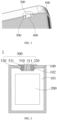
FIG. 1 is a schematic diagram of a partial structure of a battery cell according to an embodiment of this application; -
FIG. 2 is a schematic sectional view of a battery cell as viewed from one direction according to an embodiment of this application; -
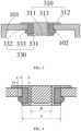
FIG. 3 is a schematic diagram of mounting a sealing assembly and a housing in the battery cell shown inFIG. 2 ; -
FIG. 4 is a schematic diagram of dimensions of a sealing assembly in the battery cell shown inFIG. 2 ; and -
FIG. 5 is a schematic diagram of an electrical device according to an embodiment of this application. - For ease of understanding this application, the following describes this application in more detail with reference to drawings and specific embodiments. It is hereby noted that an element referred to herein as being "fixed to", "fastened to", or "mounted to" another element may be directly disposed on the other element, or may be fixed or fastened to the other element with one or more elements in between. An element referred to herein as "connected to" another element may be connected to the other element directly or with one or more elements in between. The terms "vertical", "horizontal", "left", "right", "in", "out" and other similar expressions used herein are merely for ease of description.
- Unless otherwise defined, all technical and scientific terms used herein bear the same meanings as what is normally understood by a person skilled in the technical field of this application. The terms used in the specification of this application are merely intended to describe specific embodiments but not to limit this application. The term "and/or" used herein is intended to include any and all combinations of one or more relevant items recited.
- In addition, to the extent that no mutual conflict occurs, the technical features described below in different embodiments of this application may be combined with each other.
- In this specification, the meanings of "mounting" or "installation" include fixing or confining an element or unit to a specific position or place by welding/soldering, screwing, snap-fit connection, bonding, or other means, where the element or unit may be held stationary in the specific position or place or may move within a limited range, and the element or unit may be detachable or undetachable after being fixed or confined to the specific position or place, without being limited in embodiments of this application.
- Referring to
FIG. 1 and FIG. 2 , which is a schematic diagram of a partial structure of abattery cell 1 according to an embodiment of this application, and a schematic sectional view of thebattery cell 1, respectively, thebattery cell 1 includes ahousing 100, acell body 200, and a sealingassembly 300. Thehousing 100 defines anaccommodation cavity 101 inside, and includes aninjection port 102 that communicates with theaccommodation cavity 101 of thebattery cell 1. Thecell body 200 is accommodated in theaccommodation cavity 101. The sealing assembly is mounted at theinjection port 102. - With respect to the
housing 100, referring toFIG. 2 , thehousing 100 is in the shape of a flattened cuboid as a whole. Theaccommodation cavity 101 inside the housing is configured to accommodate thecell body 200 and an electrolyte. In this embodiment, thebattery cell 1 is a steel-shell cell. That is, thehousing 100 is a steel shell. Understandably, in other embodiments of this application, thebattery cell 1 may be another type of hard-shell cell instead. That is, thehousing 100 is another metal housing such as an aluminum housing. - Referring to
FIG. 2 , thecell body 200 is accommodated in theaccommodation cavity 101, and includes a first electrode plate (not shown in the drawing), a second electrode plate (not shown in the drawing), and a separator (not shown in the drawing) that are stacked. The first electrode plate and the second electrode plate have opposite polarities and are spaced out, of which one is a positive electrode plate and the other is a negative electrode plate. The separator is disposed between the two electrode plates and is configured to separate the two electrode plates. The first electrode plate, the second electrode plate, and the separator are stacked and wound into a winding structure with an oblong cross section so as to be accommodated in theaccommodation cavity 101. Understandably, although thecell body 200 in this embodiment is of a winding structure, this application is not limited to the type of the structure. In other embodiments of this application, thecell body 200 may be of a stacked structure instead. Thehousing 100 is filled with an electrolyte. Thecell body 200 is infiltrated by the electrolyte. The electrolyte is configured to provide an environment for conducting lithium ions. In this way, the lithium ions can be intercalated into the first electrode plate or the second electrode plate in time, thereby implementing charge-and-discharge processes of thebattery cell 1. - For details of the sealing
assembly 300, referring toFIG. 2 andFIG. 3 , the sealingassembly 300 is mounted at theinjection port 102, and includes asealing pin 310, a thermallydeformable piece 320, and anelastic element 330. The sealingpin 310 is vertically mounted at theinjection port 102 and fixed to thehousing 100. The sealingpin 310 includes a first through-hole 311. The first through-hole 311 communicates with theaccommodation cavity 101. The thermallydeformable piece 320 fills in the first through-hole 311 and is fixed to thesealing pin 310. Theelastic element 330 includes a second through-hole 331, and theelastic element 331 is set around the sealingpin 310 through the second through-hole 331 and fixed to theinjection port 102. The thermallydeformable piece 320 is configured to deform when a temperature is higher than a preset threshold, so that two ends of the first through-hole 311 communicate with each other to form a pressure relief channel. In this way, when the temperature of thebattery cell 1 rises above the preset threshold, the high-pressure gas generated inside it can be exhausted to the external environment of thebattery cell 1 through the pressure relief channel, thereby preventing gas-induced expansion of thebattery cell 1 and reducing or eliminating the explosion hazard of thebattery cell 1. - It is hereby noted that the "preset threshold" referred to herein means a temperature value to which the temperature of the
battery cell 1 rises so that the thermallydeformable piece 320 just deforms to form a pressure relief channel in the second through-hole 331 of theelastic element 330. When the temperature of thebattery cell 1 is higher than the preset threshold, the pressure relief channel has been formed. The preset threshold is a temperature value higher than the normal operating temperature of thebattery cell 1 but lower than a thermal runaway temperature of thebattery cell 1. In other words, when thebattery cell 1 is in a normal operating state, the temperature of the battery cell is lower than the preset threshold, so as to avoid formation of the pressure relief channel during normal operation of the battery cell. When thebattery cell 1 is in a thermal runaway state, the temperature of the battery cell is higher than the preset threshold, so as to prevent failure of exhausting gas out of thebattery cell 1 in time in the case of thermal runaway. - It is hereby noted that the "deformation" referred to herein specifically includes hot melt and shrinkage.
- With respect to the
sealing pin 310, referring toFIG. 3 , the sealingpin 310 includes apinhead 312 and apin rod 313 coaxially connected to thepinhead 312. The first through-hole 311 runs through thepin rod 313 from thepinhead 312. Thepin rod 313 is mounted onto theinjection port 102 and extends into theaccommodation cavity 101. Thepinhead 312 is exposed in the external environment of thebattery cell 1, and is fixed onto thehousing 100. Theelastic element 330 is set around thepin rod 313. - In some embodiments, along a direction perpendicular to a direction in which the
pinhead 312 extends to thepin rod 313, a cross-sectional area of a outer contour of thepinhead 312 is larger than the cross-sectional area of theinjection port 102. A rim of thepinhead 312 is hermetically fixed to thehousing 100 by welding. - In some embodiments, the sealing
pin 310 includes a metal. That is, the material of the sealingpin 310 includes a metal. - In some embodiments, the
pinhead 312 and thepin rod 313 are integrally formed. - In some embodiments, the sealing
rod 310 also serves as an electrode post, and is made of a conductive material. Thepinhead 312 of the sealing pin is exposed to the external environment of thebattery cell 1, so as to facilitate electrical connection to an external electrical load. Thepin rod 313 extends into theaccommodation cavity 101 and is electrically connected to an electrode plate in thecell body 200, so that the electrode post constitutes an external terminal of thebattery cell 1. In addition, the other electrode plate in thecell body 200 is electrically connected to thehousing 100, so that thehousing 100 as a whole constitutes another external terminal of thebattery cell 1. - The thermally
deformable piece 320 is a core element of the sealingassembly 300 capable of relieving pressure in this application. The thermallydeformable piece 320 is of a winding structure as a whole, and fills in the first through-hole 311 and is fixed to thepin rod 313. The winding structure is not limited to a cylindrical shape, but may be a quadrilateral column shape instead, or may be a winding structure with a polygonal cross-section so long as the structure can fill in and be fixed to the first through-hole 311. - The thermally
deformable piece 320 is made of a material with a relatively low melting point, thereby facilitating the thermally deformable piece to deform in the form such as melting or shrinking before thermal runaway of thebattery cell 1, so as to form a pressure relief channel in the first through-hole 311 to let the gas escape through the channel. For example, the normal operating temperature of thebattery cell 1 is lower than 100 °C, and the thermal runaway temperature of the battery cell is 150 °C. Considering that heat shrinkage can achieve the purpose of pressure relief, the thermallydeformable piece 320 is preferably made of a material that melts at 110 °C to 170 °C. Optionally, the thermallydeformable piece 320 includes at least one of polyethylene, polypropylene, polyphenylene ether, or poly(acrylonitrile-co-styrene-co-butadiene), or a combination thereof. - In some embodiments, the thermally
deformable piece 320 is an insulation piece. - The
elastic element 330 includes a fixingportion 332 and a sealingportion 333 coaxially connected to the fixingportion 332. The second through-hole 331 runs through the sealingportion 333 from the fixingportion 332. The fixingportion 332 is fixed to theinjection port 102, and the sealingportion 333 extends into theaccommodation cavity 101. - The
elastic element 330 is set around thepin rod 313 through an inner wall of the second through-hole 331, and is mounted at theinjection port 102 through an outer wall of the fixingportion 332. Optionally, the sealingpin 310 is fixed to the thermallydeformable piece 320 and theelastic element 330 by hot-melt connection. Alternatively, in other embodiments of this application, the sealingpin 310, the thermallydeformable piece 320, and theelastic element 330 may be fixed in other ways, without being limited in this application. - In some embodiments, in order to seal the injection port more firmly, along a direction perpendicular to a direction in which the fixing
portion 332 extends to the sealingportion 333, in a part of the sealingportion 333 extending into theaccommodation cavity 101, a cross-sectional area of a outer contour of the sealing portion at an end close to theinjection port 102 is larger than a cross-sectional area of theinjection port 102, and the cross-sectional area of the outer contour of the sealing portion at an end away from theinjection hole 102 is not limited. In other words, along the direction perpendicular to the fixingportion 332 and extending to the sealingportion 333, in the part of the sealingportion 333 extending into theaccommodation cavity 101, the cross-sectional area of the outer contour of the sealing portion may gradually increase, or may increase first and then decrease, or may gradually decrease, as long as it is ensured that: in the part of the sealingportion 333 extending into theaccommodation cavity 101, the cross-sectional area of the outer contour of the sealing portion at an end close to the injection port is larger than the cross-sectional area of the injection port. - In some embodiments, the fixing
portion 332 and the sealingportion 333 are integrally formed. - Understandably, the direction in which the fixing
portion 332 extends toward the sealingportion 333 is the same as the direction in which thepinhead 312 extends toward thepin rod 313. - In some embodiments, the
elastic element 330 includes at least one of ethylene-propylene rubber, silicone rubber, polyurethane rubber (UR), or fluororubber. - In some embodiments, referring to
FIG. 4 , a diameter A of theinjection port 102 satisfies: 2 mm ≤ A ≤ 5mm. - In some embodiments, a diameter B of the first through-
hole 311 satisfies: 1 mm ≤ B ≤ 4 mm. - In some embodiments, along the direction perpendicular to the fixing
portion 332 and extending to the sealingportion 333, a clearance C between theinjection port 102 and thepin rod 313 satisfies: 0.2 mm ≤ C ≤ 2 mm. - In some embodiments, along a direction perpendicular to an axial direction of the
injection port 102, a distance D between a maximum outer diameter of the sealingportion 333 and thepin rod 313 satisfies: 0.4 mm ≤ D ≤ 2.5 mm. - The
battery cell 1 according to an embodiment of this application includes ahousing 100, acell body 200, and a sealingassembly 300. The sealingassembly 300 includes asealing pin 310, a thermallydeformable piece 320, and anelastic element 330. Theelastic element 330 is set around thepin rod 332 through the second through-hole 331 and fixed to theinjection port 102. The thermallydeformable piece 320 fills in the first through-hole 311. The thermallydeformable piece 320 is configured to deform when a temperature is higher than a preset threshold, so that a pressure relief channel that communicates with both ends of the first through-hole 311 is formed in the first through-hole 311. - In contrast to the battery cell currently available in the market, the thermally
deformable piece 320 inside thebattery cell 1 according to this embodiment of this application deforms when the temperature of the battery cell is higher than the preset threshold, so that a pressure relief channel is formed in the via hole 301 of thefastener 330 to exhaust the gas in thebattery cell 1 outward to reduce safety hazards of battery cell explosion. In this way, the battery cell according to this embodiment of this application can overcome the current disadvantage that the gas in the battery cell cannot be exhausted in time when the temperature is higher than a specified value. - Understandably, although the sealing
assembly 300 of thebattery cell 1 in the foregoing embodiment includes the sealingpin 310, the thermallydeformable piece 320, and theelastic element 330 concurrently, this application is not limited to such configuration, and theelastic element 330 is omissible in some circumstances. For example, in other embodiments of this application, the sealing assembly in thebattery cell 1 may include just the sealing pin and the thermally deformable piece. In this case, the pinhead of the sealing pin is exposed outside the housing, and the pin rod extends into the housing. The thermally deformable piece fills in the first through-hole. In this way, the battery cell that includes the sealing assembly can also alleviate the current disadvantage that the gas is unable to be exhausted out of the battery cell in time when the temperature is higher than a specified value. - An embodiment of this application further provides an
electrical device 2. Referring toFIG. 5 , which is a schematic diagram of anelectrical device 2 according to an embodiment of this application, theelectrical device 2 includes thebattery cell 1 according to any one of the foregoing embodiments. In this embodiment, theelectrical device 2 is a mobile phone. Understandably, in other embodiments of this application, theelectrical device 2 may be a tablet computer, a computer, an unmanned aerial vehicle, or another electrical device that needs to be powered electrically. - Finally, it is hereby noted that the foregoing embodiments are merely intended to describe the technical solutions of this application but not to limit this application. Based on the concept of this application, the technical features in the foregoing embodiments or different embodiments may be combined, the steps may be implemented in any order, and many variations may be made to this application in different aspects, which, for brevity, are not provided in detail. Although this application has been described in detail with reference to the foregoing embodiments, a person of ordinary skill in the art understands that modifications may still be made to the technical solutions described in the foregoing embodiments, or equivalent replacements may still be made to some technical features in the technical solutions. Such modifications and replacements do not make the essence of the corresponding technical solutions depart from the scope of the technical solutions of the embodiments of this application.
Claims (14)
- A battery cell, comprising a cell body and a housing, wherein the housing defines an accommodation cavity, the cell body is accommodated in the accommodation cavity, and the housing comprises an injection port communicating with the accommodation cavity, characterized in that the battery cell further comprises:a sealing pin, vertically mounted at the injection port and fixed to the housing, wherein the sealing pin comprises a first through-hole, and the first through-hole communicates with the accommodation cavity;a thermally deformable piece, filling in the first through-hole and fixed to the sealing pin; andan elastic element, wherein the elastic element comprises a second through-hole and is set around the sealing pin through the second through-hole and fixed to the injection port, whereinthe thermally deformable piece is configured to deform when a temperature is higher than a preset threshold, so that two ends of the first through-hole communicate with each other to form a pressure relief channel.
- The battery cell according to claim 1, characterized in that
the elastic element comprises a fixing portion and a sealing portion coaxially connected to the fixing portion, the second through-hole runs through the sealing portion from the fixing portion, the fixing portion is fixed to the injection port, and the sealing portion extends into the accommodation cavity. - The battery cell according to claim 2, characterized in that
along a direction perpendicular to a direction in which the fixing portion extends to the sealing portion, in a part of the sealing portion placed in the accommodation cavity, a cross-sectional area of the sealing portion at an end close to the injection port is larger than a cross-sectional area of the injection port. - The battery cell according to claim 3, characterized in that
the sealing pin comprises a pinhead and a pin rod coaxially connected to the pinhead, the first through-hole runs through the pin rod from the pinhead, the pin rod is mounted onto the injection port, the pinhead is fixed onto the housing, and the elastic element is set around the pin rod. - The battery cell according to claim 4, characterized in that
along the direction perpendicular to the direction in which the fixing portion extends to the sealing portion, a cross-sectional area of the pinhead is larger than the cross-sectional area of the injection port, and a rim of the pinhead is hermetically fixed to the housing by welding. - The battery cell according to claim 4, characterized in that
the fixing portion and the sealing portion are integrally formed, and/or the pinhead and the pin rod are integrally formed. - The battery cell according to claim 4, characterized in thata diameter A of the injection port satisfies: 2 mm ≤ A ≤ 5mm; anda diameter B of the first through-hole satisfies: 1 mm ≤ B ≤ 4 mm.
- The battery cell according to claim 7, characterized in that
along the direction perpendicular to the direction in which the fixing portion extends to the sealing portion, a clearance C between the injection port and the pin rod satisfies: 0.2 mm ≤ C ≤ 2 mm. - The battery cell according to claim 8, characterized in that
along a direction perpendicular to an axial direction of the injection port, a distance D between a maximum outer diameter of the sealing portion and the pin rod satisfies: 0.4 mm ≤ D ≤ 2.5 mm. - The battery cell according to claim 1, characterized in that
the thermally deformable piece is an insulation piece. - The battery cell according to claim 1, characterized in that the sealing pin comprises a metal; and/orthe thermally deformable piece comprises at least one of polyethylene, polypropylene, polyphenylene ether, or poly(acrylonitrile-co-styrene-co-butadiene); and/orthe elastic element comprises at least one of ethylene-propylene rubber, silicone rubber, polyurethane rubber, or fluororubber.
- The battery cell according to claim 1, characterized in that
the housing is a stainless steel shell. - The battery cell according to claim 1, characterized in that the thermally deformable piece is configured to melt or shrink when the temperature is higher than the preset threshold, so as to form the pressure relief channel in the first through-hole.
- An electrical device, characterized in that the electrical device comprises the battery cell according to any one of claims 1 to 13.
Applications Claiming Priority (2)
| Application Number | Priority Date | Filing Date | Title |
|---|---|---|---|
| CN202111211612.1A CN114039175B (en) | 2021-10-18 | 2021-10-18 | A battery cell and an electric device |
| PCT/CN2022/123488 WO2023066024A1 (en) | 2021-10-18 | 2022-09-30 | Cell and electrical apparatus |
Publications (2)
| Publication Number | Publication Date |
|---|---|
| EP4395061A1 true EP4395061A1 (en) | 2024-07-03 |
| EP4395061A4 EP4395061A4 (en) | 2025-04-16 |
Family
ID=80135449
Family Applications (1)
| Application Number | Title | Priority Date | Filing Date |
|---|---|---|---|
| EP22882635.0A Pending EP4395061A4 (en) | 2021-10-18 | 2022-09-30 | CELL AND ELECTRICAL DEVICE |
Country Status (4)
| Country | Link |
|---|---|
| US (1) | US20240234995A1 (en) |
| EP (1) | EP4395061A4 (en) |
| CN (1) | CN114039175B (en) |
| WO (1) | WO2023066024A1 (en) |
Families Citing this family (5)
| Publication number | Priority date | Publication date | Assignee | Title |
|---|---|---|---|---|
| CN114039175B (en) * | 2021-10-18 | 2024-06-04 | 宁德新能源科技有限公司 | A battery cell and an electric device |
| CN116053697B (en) * | 2022-12-31 | 2025-04-08 | 宁德新能源科技有限公司 | Battery core and electricity utilization device |
| CN121790680A (en) * | 2023-01-17 | 2026-04-03 | 厦门新能达科技有限公司 | Battery pack and electric equipment |
| CN116454493B (en) * | 2023-06-16 | 2023-08-15 | 深圳海辰储能控制技术有限公司 | Lower plastic, top cover assembly, single battery and battery module |
| JP2025109494A (en) * | 2024-01-12 | 2025-07-25 | プライムプラネットエナジー&ソリューションズ株式会社 | Energy Storage Devices |
Family Cites Families (13)
| Publication number | Priority date | Publication date | Assignee | Title |
|---|---|---|---|---|
| DE69622525T2 (en) * | 1996-02-28 | 2003-02-27 | Matsushita Electric Industrial Co., Ltd. | sealing battery |
| US5912090A (en) * | 1996-03-08 | 1999-06-15 | Hitachi Maxell, Ltd. | Nickel-hydrogen stacked battery pack |
| JP5034156B2 (en) * | 2004-07-02 | 2012-09-26 | トヨタ自動車株式会社 | Nickel metal hydride storage battery |
| JP2013101789A (en) * | 2011-11-07 | 2013-05-23 | Toyota Motor Corp | Method for manufacturing sealed battery, sealed battery and sealing member of sealed battery |
| US9070928B2 (en) * | 2012-01-10 | 2015-06-30 | Hong-Wen Hwang | High temperature-proof device for lithium battery |
| CN205376589U (en) * | 2016-02-25 | 2016-07-06 | 宁德时代新能源科技股份有限公司 | Sealing device and secondary cell |
| CN205790092U (en) * | 2016-07-14 | 2016-12-07 | 宁德时代新能源科技股份有限公司 | Battery cap assembly and secondary cell |
| CN206685432U (en) * | 2017-02-27 | 2017-11-28 | 比亚迪股份有限公司 | A kind of battery cover board assembly and battery |
| CN208706763U (en) * | 2018-08-13 | 2019-04-05 | 深圳市比亚迪锂电池有限公司 | Sealing nail and battery for battery liquid-filling hole |
| CN211980653U (en) * | 2020-03-23 | 2020-11-20 | 比亚迪股份有限公司 | Covers, Power Batteries and Automobiles |
| CN212277320U (en) * | 2020-06-22 | 2021-01-01 | 比亚迪股份有限公司 | Packaging components for batteries, power batteries and automobiles |
| CN113131083B (en) * | 2021-03-30 | 2023-10-13 | 宁德新能源科技有限公司 | Batteries, sealing plugs and electrical devices |
| CN114039175B (en) * | 2021-10-18 | 2024-06-04 | 宁德新能源科技有限公司 | A battery cell and an electric device |
-
2021
- 2021-10-18 CN CN202111211612.1A patent/CN114039175B/en active Active
-
2022
- 2022-09-30 WO PCT/CN2022/123488 patent/WO2023066024A1/en not_active Ceased
- 2022-09-30 EP EP22882635.0A patent/EP4395061A4/en active Pending
-
2024
- 2024-03-27 US US18/617,737 patent/US20240234995A1/en active Pending
Also Published As
| Publication number | Publication date |
|---|---|
| WO2023066024A1 (en) | 2023-04-27 |
| CN114039175B (en) | 2024-06-04 |
| CN114039175A (en) | 2022-02-11 |
| US20240234995A1 (en) | 2024-07-11 |
| EP4395061A4 (en) | 2025-04-16 |
Similar Documents
| Publication | Publication Date | Title |
|---|---|---|
| US20240234995A1 (en) | Battery cell and electrical device | |
| US20230335873A1 (en) | Battery | |
| CN101997133B (en) | Rechargeable battery | |
| EP1599915B1 (en) | Lithium ion batteries | |
| CN201508864U (en) | A battery cover assembly, a single battery and a battery pack | |
| KR100467703B1 (en) | Cap assembly and secondary battery applying the same | |
| CN109980155B (en) | Cover plate assembly for lithium ion battery and energy storage device | |
| KR20220145396A (en) | End cover assembly, battery cell, evacuation method thereof, battery and electrical device | |
| JP7482160B2 (en) | Pole assemblies, battery cells and electrical equipment | |
| KR102308423B1 (en) | Battery Cell Having a Top Cap on Which a Shape Memory Alloy Is Formed | |
| CN217768684U (en) | Cylindrical battery cell | |
| CN218867177U (en) | Battery cells, batteries and electrical devices | |
| EP4068487A1 (en) | Sealing plug, battery cell, and electric apparatus | |
| EP4456278A1 (en) | End cap assembly, battery cell, battery and electric device | |
| CN113412553A (en) | Top cap subassembly, secondary cell and electric device | |
| CN109716555A (en) | Rechargeable battery | |
| US20250070432A1 (en) | Battery cell, battery, and electric device | |
| CN209183613U (en) | Secondary batteries and battery modules | |
| KR102335696B1 (en) | The Current Interrupt Device And The Cap Assembly | |
| JP2001185201A (en) | Sealed battery | |
| KR20120047114A (en) | Secondary battery | |
| EP3726625B1 (en) | Battery system and electric automobile | |
| KR20150051516A (en) | Cap assembly and secondary battery comprising the same | |
| CN221102246U (en) | Cover plate of cylindrical battery and cylindrical battery | |
| KR101679412B1 (en) | Hollow-shaped secondary battery |
Legal Events
| Date | Code | Title | Description |
|---|---|---|---|
| STAA | Information on the status of an ep patent application or granted ep patent |
Free format text: STATUS: THE INTERNATIONAL PUBLICATION HAS BEEN MADE |
|
| PUAI | Public reference made under article 153(3) epc to a published international application that has entered the european phase |
Free format text: ORIGINAL CODE: 0009012 |
|
| STAA | Information on the status of an ep patent application or granted ep patent |
Free format text: STATUS: REQUEST FOR EXAMINATION WAS MADE |
|
| 17P | Request for examination filed |
Effective date: 20240327 |
|
| AK | Designated contracting states |
Kind code of ref document: A1 Designated state(s): AL AT BE BG CH CY CZ DE DK EE ES FI FR GB GR HR HU IE IS IT LI LT LU LV MC MK MT NL NO PL PT RO RS SE SI SK SM TR |
|
| DAV | Request for validation of the european patent (deleted) | ||
| DAX | Request for extension of the european patent (deleted) | ||
| REG | Reference to a national code |
Ref country code: DE Ref legal event code: R079 Free format text: PREVIOUS MAIN CLASS: H01M0050627000 Ipc: H01M0050655000 |
|
| A4 | Supplementary search report drawn up and despatched |
Effective date: 20250319 |
|
| RIC1 | Information provided on ipc code assigned before grant |
Ipc: H01M 50/342 20210101ALI20250313BHEP Ipc: H01M 50/184 20210101ALI20250313BHEP Ipc: H01M 50/325 20210101ALI20250313BHEP Ipc: H01M 50/183 20210101ALI20250313BHEP Ipc: H01M 50/627 20210101ALI20250313BHEP Ipc: H01M 50/655 20210101AFI20250313BHEP |