EP4395059A1 - Battery cell with chamfered protective tape - Google Patents
Battery cell with chamfered protective tape Download PDFInfo
- Publication number
- EP4395059A1 EP4395059A1 EP22904612.3A EP22904612A EP4395059A1 EP 4395059 A1 EP4395059 A1 EP 4395059A1 EP 22904612 A EP22904612 A EP 22904612A EP 4395059 A1 EP4395059 A1 EP 4395059A1
- Authority
- EP
- European Patent Office
- Prior art keywords
- anode
- cathode
- tab
- protective tape
- battery cell
- Prior art date
- Legal status (The legal status is an assumption and is not a legal conclusion. Google has not performed a legal analysis and makes no representation as to the accuracy of the status listed.)
- Pending
Links
Images


Classifications
-
- H—ELECTRICITY
- H01—ELECTRIC ELEMENTS
- H01M—PROCESSES OR MEANS, e.g. BATTERIES, FOR THE DIRECT CONVERSION OF CHEMICAL ENERGY INTO ELECTRICAL ENERGY
- H01M10/00—Secondary cells; Manufacture thereof
- H01M10/05—Accumulators with non-aqueous electrolyte
- H01M10/052—Li-accumulators
-
- H—ELECTRICITY
- H01—ELECTRIC ELEMENTS
- H01M—PROCESSES OR MEANS, e.g. BATTERIES, FOR THE DIRECT CONVERSION OF CHEMICAL ENERGY INTO ELECTRICAL ENERGY
- H01M10/00—Secondary cells; Manufacture thereof
- H01M10/05—Accumulators with non-aqueous electrolyte
- H01M10/058—Construction or manufacture
-
- H—ELECTRICITY
- H01—ELECTRIC ELEMENTS
- H01M—PROCESSES OR MEANS, e.g. BATTERIES, FOR THE DIRECT CONVERSION OF CHEMICAL ENERGY INTO ELECTRICAL ENERGY
- H01M10/00—Secondary cells; Manufacture thereof
- H01M10/05—Accumulators with non-aqueous electrolyte
- H01M10/058—Construction or manufacture
- H01M10/0587—Construction or manufacture of accumulators having only wound construction elements, i.e. wound positive electrodes, wound negative electrodes and wound separators
-
- H—ELECTRICITY
- H01—ELECTRIC ELEMENTS
- H01M—PROCESSES OR MEANS, e.g. BATTERIES, FOR THE DIRECT CONVERSION OF CHEMICAL ENERGY INTO ELECTRICAL ENERGY
- H01M10/00—Secondary cells; Manufacture thereof
- H01M10/42—Methods or arrangements for servicing or maintenance of secondary cells or secondary half-cells
- H01M10/4235—Safety or regulating additives or arrangements in electrodes, separators or electrolyte
-
- H—ELECTRICITY
- H01—ELECTRIC ELEMENTS
- H01M—PROCESSES OR MEANS, e.g. BATTERIES, FOR THE DIRECT CONVERSION OF CHEMICAL ENERGY INTO ELECTRICAL ENERGY
- H01M50/00—Constructional details or processes of manufacture of the non-active parts of electrochemical cells other than fuel cells, e.g. hybrid cells
- H01M50/10—Primary casings; Jackets or wrappings
- H01M50/172—Arrangements of electric connectors penetrating the casing
- H01M50/174—Arrangements of electric connectors penetrating the casing adapted for the shape of the cells
- H01M50/178—Arrangements of electric connectors penetrating the casing adapted for the shape of the cells for pouch or flexible bag cells
-
- H—ELECTRICITY
- H01—ELECTRIC ELEMENTS
- H01M—PROCESSES OR MEANS, e.g. BATTERIES, FOR THE DIRECT CONVERSION OF CHEMICAL ENERGY INTO ELECTRICAL ENERGY
- H01M50/00—Constructional details or processes of manufacture of the non-active parts of electrochemical cells other than fuel cells, e.g. hybrid cells
- H01M50/10—Primary casings; Jackets or wrappings
- H01M50/183—Sealing members
- H01M50/184—Sealing members characterised by their shape or structure
-
- H—ELECTRICITY
- H01—ELECTRIC ELEMENTS
- H01M—PROCESSES OR MEANS, e.g. BATTERIES, FOR THE DIRECT CONVERSION OF CHEMICAL ENERGY INTO ELECTRICAL ENERGY
- H01M50/00—Constructional details or processes of manufacture of the non-active parts of electrochemical cells other than fuel cells, e.g. hybrid cells
- H01M50/10—Primary casings; Jackets or wrappings
- H01M50/183—Sealing members
- H01M50/186—Sealing members characterised by the disposition of the sealing members
-
- H—ELECTRICITY
- H01—ELECTRIC ELEMENTS
- H01M—PROCESSES OR MEANS, e.g. BATTERIES, FOR THE DIRECT CONVERSION OF CHEMICAL ENERGY INTO ELECTRICAL ENERGY
- H01M50/00—Constructional details or processes of manufacture of the non-active parts of electrochemical cells other than fuel cells, e.g. hybrid cells
- H01M50/50—Current conducting connections for cells or batteries
- H01M50/531—Electrode connections inside a battery casing
-
- H—ELECTRICITY
- H01—ELECTRIC ELEMENTS
- H01M—PROCESSES OR MEANS, e.g. BATTERIES, FOR THE DIRECT CONVERSION OF CHEMICAL ENERGY INTO ELECTRICAL ENERGY
- H01M50/00—Constructional details or processes of manufacture of the non-active parts of electrochemical cells other than fuel cells, e.g. hybrid cells
- H01M50/50—Current conducting connections for cells or batteries
- H01M50/531—Electrode connections inside a battery casing
- H01M50/533—Electrode connections inside a battery casing characterised by the shape of the leads or tabs
-
- H—ELECTRICITY
- H01—ELECTRIC ELEMENTS
- H01M—PROCESSES OR MEANS, e.g. BATTERIES, FOR THE DIRECT CONVERSION OF CHEMICAL ENERGY INTO ELECTRICAL ENERGY
- H01M50/00—Constructional details or processes of manufacture of the non-active parts of electrochemical cells other than fuel cells, e.g. hybrid cells
- H01M50/50—Current conducting connections for cells or batteries
- H01M50/531—Electrode connections inside a battery casing
- H01M50/534—Electrode connections inside a battery casing characterised by the material of the leads or tabs
-
- H—ELECTRICITY
- H01—ELECTRIC ELEMENTS
- H01M—PROCESSES OR MEANS, e.g. BATTERIES, FOR THE DIRECT CONVERSION OF CHEMICAL ENERGY INTO ELECTRICAL ENERGY
- H01M50/00—Constructional details or processes of manufacture of the non-active parts of electrochemical cells other than fuel cells, e.g. hybrid cells
- H01M50/10—Primary casings; Jackets or wrappings
- H01M50/183—Sealing members
- H01M50/19—Sealing members characterised by the material
- H01M50/193—Organic material
-
- H—ELECTRICITY
- H01—ELECTRIC ELEMENTS
- H01M—PROCESSES OR MEANS, e.g. BATTERIES, FOR THE DIRECT CONVERSION OF CHEMICAL ENERGY INTO ELECTRICAL ENERGY
- H01M50/00—Constructional details or processes of manufacture of the non-active parts of electrochemical cells other than fuel cells, e.g. hybrid cells
- H01M50/50—Current conducting connections for cells or batteries
- H01M50/572—Means for preventing undesired use or discharge
- H01M50/584—Means for preventing undesired use or discharge for preventing incorrect connections inside or outside the batteries
- H01M50/586—Means for preventing undesired use or discharge for preventing incorrect connections inside or outside the batteries inside the batteries, e.g. incorrect connections of electrodes
-
- H—ELECTRICITY
- H01—ELECTRIC ELEMENTS
- H01M—PROCESSES OR MEANS, e.g. BATTERIES, FOR THE DIRECT CONVERSION OF CHEMICAL ENERGY INTO ELECTRICAL ENERGY
- H01M50/00—Constructional details or processes of manufacture of the non-active parts of electrochemical cells other than fuel cells, e.g. hybrid cells
- H01M50/50—Current conducting connections for cells or batteries
- H01M50/572—Means for preventing undesired use or discharge
- H01M50/584—Means for preventing undesired use or discharge for preventing incorrect connections inside or outside the batteries
- H01M50/59—Means for preventing undesired use or discharge for preventing incorrect connections inside or outside the batteries characterised by the protection means
- H01M50/595—Tapes
-
- Y—GENERAL TAGGING OF NEW TECHNOLOGICAL DEVELOPMENTS; GENERAL TAGGING OF CROSS-SECTIONAL TECHNOLOGIES SPANNING OVER SEVERAL SECTIONS OF THE IPC; TECHNICAL SUBJECTS COVERED BY FORMER USPC CROSS-REFERENCE ART COLLECTIONS [XRACs] AND DIGESTS
- Y02—TECHNOLOGIES OR APPLICATIONS FOR MITIGATION OR ADAPTATION AGAINST CLIMATE CHANGE
- Y02E—REDUCTION OF GREENHOUSE GAS [GHG] EMISSIONS, RELATED TO ENERGY GENERATION, TRANSMISSION OR DISTRIBUTION
- Y02E60/00—Enabling technologies; Technologies with a potential or indirect contribution to GHG emissions mitigation
- Y02E60/10—Energy storage using batteries
-
- Y—GENERAL TAGGING OF NEW TECHNOLOGICAL DEVELOPMENTS; GENERAL TAGGING OF CROSS-SECTIONAL TECHNOLOGIES SPANNING OVER SEVERAL SECTIONS OF THE IPC; TECHNICAL SUBJECTS COVERED BY FORMER USPC CROSS-REFERENCE ART COLLECTIONS [XRACs] AND DIGESTS
- Y02—TECHNOLOGIES OR APPLICATIONS FOR MITIGATION OR ADAPTATION AGAINST CLIMATE CHANGE
- Y02P—CLIMATE CHANGE MITIGATION TECHNOLOGIES IN THE PRODUCTION OR PROCESSING OF GOODS
- Y02P70/00—Climate change mitigation technologies in the production process for final industrial or consumer products
- Y02P70/50—Manufacturing or production processes characterised by the final manufactured product
Definitions
- the present disclosure relates to a battery cell with chamfered protective tape.
- lithium secondary battery exhibiting a high energy density and operating voltage, a long cycle lifespan, and a low self-discharge rate, which is now commercialized and widely used.
- the protective tape may be made of casted polypropylene (CPP).
- the chamfering may be performed within a portion where the cathode tab and the anode tab are formed from the opposite ends of the protective tape.
- the cathode and the anode each have a flat portion where the active material layer has a constant thickness, and an inclined portion where the thickness of the active material layer in the flat portion gradually decreases,
- the cathode tab and the anode tab are jointed to a cathode lead and an anode lead, respectively, and the cathode lead and the anode lead may be jointed to a first bent portion of the cathode tab and a second bent portion of the anode tab.
- the cathode lead and the anode lead protrude toward the outside of the battery case, and an insulating tape is formed at a portion where the cathode lead and the anode lead come into contact with the battery case.
- the insulating tape may be made of one or more materials selected from the group consisting of polyphenyleneether (PPE), polyimide (PI), polypropylene (PP), polyethyleneterephthalate (PET), polyphenylene sulfide (PPS), and polyethylene (PE).
- PPE polyphenyleneether
- PI polyimide
- PP polypropylene
- PET polyethyleneterephthalate
- PPS polyphenylene sulfide
- PE polyethylene
- the material constituting the protective tape is not limited as long as it is an organic material having insulation and adhesive property, but specifically, it may be casted polypropylene (CPP).
- CPP casted polypropylene
- the protective tape may have a structure in which upper parts at both ends are chamfered.
- the present inventors have confirmed that a protective tape is entirely attached to the upper and lower portions of the electrode assembly so as to cover the top areas of the electrode assembly adjacent to the first bent portion of the cathode tab and the second bent portion of the anode tab, thereby capable of solving the resistance deviation problem.
- the present inventors have conducted in-depth research to solve these problems, and as a result, have found that when attaching the protective tape having a structure where the upper parts at both ends are chamfered, it can reduce the problem of deterioration of sealing property that the protective tape subsequently causes interference with the battery case, and completed the present disclosure.
- the battery cell 100 is configured such that the electrode assembly 110 is incorporated in the battery case 120, the cathode tab 111 and the anode tab 112 protrude side by side from the cathode current collector and the anode current collector of the electrode assembly 110 so as not to overlap each other, and the cathode tab 111 and the anode tab 112 are jointed to the cathode lead 141 and the anode lead 142, respectively.
- the cathode tab 111 and the anode tab 112 each have a first bent portion and a second bent portion that are bent into a v shape by a v-forming process as shown in Fig. 3 .
- the cathode lead 141 and the anode lead 142 are jointed to the cathode tab 111 and the anode tab 112, respectively, and the cathode lead 141 and anode lead 142 each protrude toward the outside of the battery case 120, and an insulating tapes 151 and 152 are formed at portions in contact with the battery case 120.
- the battery cell 100 is configured such that at the first bent portion and the second bent portion in the region where bending is performed according to the v-formation of these tabs, and at the top area of the electrode assembly 110 adjacent to the first bent portion and the second bent portion, a protective tape 130 is attached to the upper and lower portions to cover them.
- the protective tape 130 has a structure in which upper portions at both ends are chamfered.
- the protection tape 130 may have a structure in which upper portions at both ends are chamfered in a curved shape as shown in Fig. 4(a) , in a diagonal shape as shown in Fig. 4(b) , or in a rectangular shape as in shown Fig. 4(c) .
- the protective tape 130 has a structure capable of sufficiently performing the role of short circuit protection together with the improvement of sealing interference.
- This chamfered protective tape 130 can be formed by a very simple method, and specifically, it can be manufactured by cutting a long bar-shaped protective tape reel with a Y-shaped punch at intervals corresponding to the width of the electrode assembly. Accordingly, the present disclosure also provides a method for manufacturing such a protective tape.
- the cathode and the anode each have a flat portion where the active material layer has a constant thickness and an inclined portion where the thickness of the active material layer in the flat portion gradually decreases, and the inclined portion is formed at an end in a direction in which the cathode tab 111 and the anode tab 112 protrude.
- the top area of the electrode assembly 110 where the protective tape 130 is formed may be a portion corresponding to the inclined portion of these electrodes.
- a separate protective tape 130 is formed on the top area of the electrode assembly 110 corresponding to the inclined portion of the electrode, whereby when a lamination process or the like is subsequently performed, the protective tape 130 may cover the thickness difference between the flat portion and the inclined portion, and thus, a portion corresponding to the inclined portion of the electrode can also receive the same pressure, which is thus preferable.
- the protective tape is formed only on one side of the anode tab.
- the length of the protective tape 130 according to the present disclosure is formed to a length 1 that can cover the upper portion of the electrode assembly 110 adjacent to the cathode electrode tab 111 and the anode tab 112.
- the thickness (t) of the protective tape 130 may be 10 ⁇ m to 100 ⁇ m, specifically 20 ⁇ m to 50 ⁇ m , within a range that does not increase the volume of the battery cell 100.
- the thickness is too thin outside the above range, the effect of the protective tape cannot be exhibited, and if the thickness is too thick, it may increase the volume of the battery cell, which is thus not preferable.
- the battery cell according to the present disclosure may be specifically a lithium secondary battery.
- the battery cell according to the present disclosure is configured such that the protective tape is formed in a shape of covering both the bent portions of the cathode tab and the anode tab, so that the pressure deviation in the longitudinal direction generated at the top area of the electrode assembly where the cathode tab and the anode tab are formed can be reduced, and the internal resistance deviation due to non-uniform pressure can be reduced, thereby improving cell performance.
- the upper portions at both ends are chamfered so that the protective tape can be easily folded by v-formation, so that it is possible to solve the problem of deterioration of sealing properties that the protective tape causes interference with the battery case, thereby improving safety and cell performance.
Landscapes
- Chemical & Material Sciences (AREA)
- Chemical Kinetics & Catalysis (AREA)
- Electrochemistry (AREA)
- General Chemical & Material Sciences (AREA)
- Engineering & Computer Science (AREA)
- Manufacturing & Machinery (AREA)
- Connection Of Batteries Or Terminals (AREA)
- Secondary Cells (AREA)
Abstract
wherein the cathode has a cathode tab extending from a cathode current collector formed on one side, and the anode has an anode tab extending from an anode current collector formed on one side,
wherein at the top area of the electrode assembly where the cathode tab and the anode tab protrude, the cathode tab and the anode tab each have a first bent portion and a second bent portion that are bent in a v shape,
wherein a protective tape is attached to the first bent portion, the second bent portion, and top areas of the electrode assembly adjacent to the first and second bent portions so as to cover them, and
wherein upper parts at both ends of the protective tape are chamfered.
Description
- This application claims the benefit of
Korean Patent Application No. 10-2021-0173785 filed on December 7, 2021 - The present disclosure relates to a battery cell with chamfered protective tape.
- With the technology development and increased demand for mobile devices, demand for secondary batteries as energy sources has been rapidly increasing. Among such secondary batteries is a lithium secondary battery exhibiting a high energy density and operating voltage, a long cycle lifespan, and a low self-discharge rate, which is now commercialized and widely used.
- Moreover, in recent years, the design itself of electronic devices has played a very important role in product selection by consumers, and the electronic devices have been gradually miniaturized and thinned according to the taste of consumer. Thereby, in order to minimize unnecessary waste of internal space of electronic devices, lithium secondary batteries are also required to be miniaturized and thinned, and the demand for them is increasing.
- Such a lithium secondary battery is manufactured by fabricating a cathode and an anode, stacking them together with a separator to form an electrode assembly, and incorporating the electrode assembly together with an electrolyte solution in a secondary battery case.
- Meanwhile, at this time, a process of attaching a protective tape to the jointing portion between a tab and a lead of the electrode assembly and v-forming the tab is performed. However, such a protective tape is generally attached only to the anode portion, which causes a pressure deviation between the cathode and the anode according to the pressing process of the manufactured electrode assembly, resulting in non-uniform adhesive property. Such non-uniform adhesive property ultimately causes a problem of variations in internal resistance due to cycles of the secondary battery.
- Therefore, there is an urgent need to develop a secondary battery technology that can solve these problems.
- It is an object of the present disclosure to provide a battery cell that can reduce pressure deviation in the longitudinal direction occurring at the top area of an electrode assembly where a cathode tab and an anode tab are formed, and reduce internal resistance deviation due to non-uniform pressure, thereby improving cell performance.
- It is another object of the present disclosure to provide a battery cell that can solve the process problem at the edge of the protective tape that may occur in this process, and thus solve the problem of deterioration in sealing property that the protective tap subsequently causes interference with the battery case.
- It is yet another object of the present disclosure to provide a method that can very easily manufacture the protective tape used for such a battery cell.
- According to one embodiment of the present disclosure, there is provided a battery cell for a secondary battery in which an electrode assembly including a cathode, an anode, and a separator interposed between the cathode and the anode is incorporated in a battery case,
- wherein the cathode has a cathode tab extending from a cathode current collector formed on one side, and the anode has an anode tab extending from an anode current collector formed on one side,
- wherein at the top area of the electrode assembly where the cathode tab and the anode tab protrude, the cathode tab and the anode tab each have a first bent portion and a second bent portion that are bent in a v shape,
- wherein a protective tape is attached to the first bent portion, the second bent portion, and top areas of the electrode assembly adjacent to the first and second bent portions so as to cover them, and
- wherein upper parts at both ends of the protective tape are chamfered.
- Here, the protective tape may be made of casted polypropylene (CPP).
- The protective tape may be chamfered in a curved, diagonal or rectangular shape.
- At this time, the chamfering may be performed within a portion where the cathode tab and the anode tab are formed from the opposite ends of the protective tape.
- A thickness of the protective tape may be 10 µm to 100 µm.
- A length of the protective tape may be a length that can cover the top area of the electrode assembly adjacent to the cathode tab and the anode tab.
- Meanwhile, the cathode and the anode each have a flat portion where the active material layer has a constant thickness, and an inclined portion where the thickness of the active material layer in the flat portion gradually decreases,
- the inclined portion is formed at an end in a direction in which the cathode tab of the cathode and the anode tab of the anode protrude, and
- the top area of the electrode assembly where the protective tape is formed may be a portion corresponding to the inclined portion.
- The cathode tab and the anode tab are jointed to a cathode lead and an anode lead, respectively, and the cathode lead and the anode lead may be jointed to a first bent portion of the cathode tab and a second bent portion of the anode tab.
- Further, the cathode lead and the anode lead protrude toward the outside of the battery case, and an insulating tape is formed at a portion where the cathode lead and the anode lead come into contact with the battery case.
- At this time, the insulating tape may be made of one or more materials selected from the group consisting of polyphenyleneether (PPE), polyimide (PI), polypropylene (PP), polyethyleneterephthalate (PET), polyphenylene sulfide (PPS), and polyethylene (PE).
- Meanwhile, the battery cell may be a lithium secondary battery.
- According to another embodiment of the present disclosure, there is provided a method of manufacturing a protective tape for a secondary battery, comprising: cutting a long bar-shaped protective tape reel with a Y-shaped punch at intervals corresponding to the width of an electrode assembly.
-
-
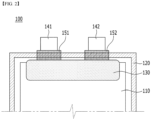
Fig. 1 shows a planar transmission before v-formation of a tab of a battery cell according to one embodiment of the present disclosure; -
Fig. 2 shows a planar transmission after v-formation of a tab in the battery cell ofFig. 1 ; -
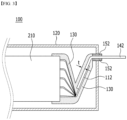
Fig. 3 is a cross-sectional view of the battery cell ofFig. 1 ; -
Fig. 4 is schematic views of the protective tape used inFig. 1 . - The terms and words used in the present specification and claims should not be interpreted as being limited to typical meanings or dictionary definitions, but should be interpreted as having meanings and concepts relevant to the technical scope of the present disclosure based on the rule according to which an inventor can appropriately define the terms and words as terms for describing most appropriately the best method the inventor knows for carrying out the invention. Accordingly, the embodiments described herein and the configurations shown in the drawings are only most preferable embodiments of the present disclosure and do not represent the entire spirit of the present disclosure, so it should be appreciated that there may be various equivalents and modifications that can replace the embodiments and the configurations at the time at which the present application is filed, and the scope of the present disclosure is not limited to the embodiments described below.
- Hereinafter, the present disclosure will be described in detail with reference to the accompanying drawings. The terms or words used in the present specification and claims should not be construed as being limited to typical meanings or dictionary definitions, and the present disclosure should be construed with meanings and concepts that are consistent with the technical idea of the present disclosure based on the principle that the inventors may appropriately define concepts of the terms to appropriately describe their own disclosure in the best way.
- Further, the embodiments described herein and the configurations shown in the drawings are only most preferable embodiments of the present disclosure and do not represent the entire spirit of the present disclosure, so it should be appreciated that there may be various equivalents and modifications that can replace the embodiments and the configurations at the time at which the present application is filed.
- According to one embodiment of the present disclosure, there is provided a battery cell for a secondary battery in which an electrode assembly including a cathode, an anode, and a separator interposed between the cathode and the anode is incorporated in a battery case,
- wherein the cathode has a cathode tab extending from a cathode current collector formed on one side, and the anode has an anode tab extending from an anode current collector formed on one side,
- wherein at the top area of the electrode assembly where the cathode tab and the anode tab protrude, the cathode tab and the anode tab each have a first bent portion and a second bent portion that are bent in a v shape,
- wherein a protective tape is attached to the first bent portion, the second bent portion, and top areas of the electrode assembly adjacent to the first and second bent portions so as to cover them, and
- wherein upper parts at both ends of the protective tape are chamfered.
- At this time, the material constituting the protective tape is not limited as long as it is an organic material having insulation and adhesive property, but specifically, it may be casted polypropylene (CPP).
- The casted polypropylene has low reactivity with internal materials such as an electrolyte solution and is a material equal to PP used inside the battery case for sealing. Therefore, even if it overlaps the sealing area, it is possible to prevent a phenomenon of rapid deterioration of the sealing property, so it is suitable for use of such a protective tape.
- Meanwhile, the protective tape may have a structure in which upper parts at both ends are chamfered.
- As described above, when an electrode assembly is mounted in a battery case made of a laminate sheet in a typical pouch-type battery cell, electrode tabs are V-formed and connected to electrode leads to increase a space efficiency of the upper portion. During this process, since a short circuit may occur from the electrode constituting the outermost part due to impacts or drops, and the like, a device capable of protecting them is required.
- Thereby, conventionally, a protective tape was attached, but it was manufactured so that the anode was mainly located at the outermost part, so that the protective tape was attached only to the v-forming portion of the anode tab and a part of the top area of the electrode assembly connected thereto.
- However, when attached in this way, there was a problem that internal resistance deviation occurs due to non-uniform pressure in the longitudinal direction generated at the top area of the electrode assembly where the cathode tab and the anode tab are formed, thereby deteriorating cell performance.
- In this regard, the present inventors have confirmed that a protective tape is entirely attached to the upper and lower portions of the electrode assembly so as to cover the top areas of the electrode assembly adjacent to the first bent portion of the cathode tab and the second bent portion of the anode tab, thereby capable of solving the resistance deviation problem.
- However, when attaching the protective tape, there is a problem that the top area of the protective tape is not properly folded during the v-folding process of the tap, and unfolded, which causes interference with the sealing area, resulting in a sealing problem.
- Therefore, the present inventors have conducted in-depth research to solve these problems, and as a result, have found that when attaching the protective tape having a structure where the upper parts at both ends are chamfered, it can reduce the problem of deterioration of sealing property that the protective tape subsequently causes interference with the battery case, and completed the present disclosure.
- In order to obtain such an effect most effectively, it is preferable that the protective tape is not folded the best during the v-formation of the tab, and thus is not formed in a portion where sealing interference easily occurs, and has a structure that can protect the tabs as a whole, whereby it may be the shape where the upper portions at both ends are chamfered.
- This configuration is shown in
Figs. 1 to 4 below, and will be described in more detail with reference to the figures below. - First,
Fig. 1 shows a planar transmission before v-formation of a tab of a battery cell according to one embodiment of the present disclosure, andFig. 2 shows planar transmission after v-formation of a tab in the battery cell ofFig. 1 . - In addition, in order to more specifically describe the bent portion where the v-formation is performed,
Fig. 3 shows a cross-sectional view of the battery cell ofFig. 1 , andFig. 4 shows schematic views of the protective tape used inFig. 1 for explaining the shape of the protective tape in more detail. - Referring to
Figs. 1 to 4 , thebattery cell 100 is configured such that theelectrode assembly 110 is incorporated in thebattery case 120, thecathode tab 111 and theanode tab 112 protrude side by side from the cathode current collector and the anode current collector of theelectrode assembly 110 so as not to overlap each other, and thecathode tab 111 and theanode tab 112 are jointed to thecathode lead 141 and theanode lead 142, respectively. - Here, the
cathode tab 111 and theanode tab 112 each have a first bent portion and a second bent portion that are bent into a v shape by a v-forming process as shown inFig. 3 . - In these bent portions, the
cathode lead 141 and theanode lead 142 are jointed to thecathode tab 111 and theanode tab 112, respectively, and thecathode lead 141 andanode lead 142 each protrude toward the outside of thebattery case 120, and an insulatingtapes battery case 120. - The insulating tape is not limited as long as it is a material capable of enhancing adhesion to the battery case and improving sealing properties. For example, the insulating tape may be made of one or more materials selected from the group consisting of polyphenyleneether (PPE), polyimide (PI), polypropylene (PP), polyethyleneterephthalate (PET), polyphenylene sulfide (PPS), and polyethylene (PE).
- Meanwhile, the
battery cell 100 according to one embodiment of the present disclosure is configured such that at the first bent portion and the second bent portion in the region where bending is performed according to the v-formation of these tabs, and at the top area of theelectrode assembly 110 adjacent to the first bent portion and the second bent portion, aprotective tape 130 is attached to the upper and lower portions to cover them. - Referring to
Figs. 1 and4 together, theprotective tape 130 has a structure in which upper portions at both ends are chamfered. - At this time, the
protection tape 130 may have a structure in which upper portions at both ends are chamfered in a curved shape as shown inFig. 4(a) , in a diagonal shape as shown inFig. 4(b) , or in a rectangular shape as in shownFig. 4(c) . - In addition, as can be seen in
Fig. 1 , such chamfering is performed from both ends of theprotective tape 130 within the portion where thecathode tab 111 and theanode tab 112 are formed, so that thecathode tab 111 and theanode tab 112 are entirely covered by theprotective tape 130, whereby the chamfer does not affect thecathode tab 111 and theanode tab 112, thetabs protective tape 130. Thus, theprotective tape 130 has a structure capable of sufficiently performing the role of short circuit protection together with the improvement of sealing interference. - This chamfered
protective tape 130 can be formed by a very simple method, and specifically, it can be manufactured by cutting a long bar-shaped protective tape reel with a Y-shaped punch at intervals corresponding to the width of the electrode assembly. Accordingly, the present disclosure also provides a method for manufacturing such a protective tape. - Meanwhile, although not shown in the figures, the cathode and the anode each have a flat portion where the active material layer has a constant thickness and an inclined portion where the thickness of the active material layer in the flat portion gradually decreases, and the inclined portion is formed at an end in a direction in which the
cathode tab 111 and theanode tab 112 protrude. At this time, the top area of theelectrode assembly 110 where theprotective tape 130 is formed may be a portion corresponding to the inclined portion of these electrodes. - In this case, a separate
protective tape 130 is formed on the top area of theelectrode assembly 110 corresponding to the inclined portion of the electrode, whereby when a lamination process or the like is subsequently performed, theprotective tape 130 may cover the thickness difference between the flat portion and the inclined portion, and thus, a portion corresponding to the inclined portion of the electrode can also receive the same pressure, which is thus preferable. - Meanwhile, conventionally, the protective tape is formed only on one side of the anode tab. Thus, in order to reduce the pressure difference between the top area of the electrode assembly adjacent to the positive tab and the top area of the electrode assembly adjacent to the anode tab, the length of the
protective tape 130 according to the present disclosure is formed to a length 1 that can cover the upper portion of theelectrode assembly 110 adjacent to thecathode electrode tab 111 and theanode tab 112. - Therefore, according to the present disclosure, the pressure deviation in the longitudinal direction of the top area of the electrode assembly is reduced, whereby the internal resistance deviation is also reduced, so that further improved cell performance can be obtained.
- Furthermore, the thickness (t) of the
protective tape 130 may be 10 µm to 100 µm, specifically 20 µm to 50 µm, within a range that does not increase the volume of thebattery cell 100. - If the thickness is too thin outside the above range, the effect of the protective tape cannot be exhibited, and if the thickness is too thick, it may increase the volume of the battery cell, which is thus not preferable.
- Other components other than the protective tape, specific manufacturing methods of cathodes, anodes, separators, battery cases, and the like, and constituent materials are well known in the art, and therefore, descriptions thereof are omitted herein.
- Meanwhile, the battery cell according to the present disclosure may be specifically a lithium secondary battery.
- Other components of the lithium secondary battery are well known in the art, and therefore, descriptions thereof are omitted herein.
- Although the exemplary embodiments of the present disclosure have been disclosed for illustrative purposes, those skilled in the art will appreciate that various modifications, additions and substitutions are possible, without departing from the scope and spirit of the invention as disclosed in the accompanying claims.
- The battery cell according to the present disclosure is configured such that the protective tape is formed in a shape of covering both the bent portions of the cathode tab and the anode tab, so that the pressure deviation in the longitudinal direction generated at the top area of the electrode assembly where the cathode tab and the anode tab are formed can be reduced, and the internal resistance deviation due to non-uniform pressure can be reduced, thereby improving cell performance.
- In addition, the upper portions at both ends are chamfered so that the protective tape can be easily folded by v-formation, so that it is possible to solve the problem of deterioration of sealing properties that the protective tape causes interference with the battery case, thereby improving safety and cell performance.
- Furthermore, it is effective in manufacturing such a protective tape by a very simple method.
Claims (12)
- A battery cell for a secondary battery in which an electrode assembly including a cathode, an anode, and a separator interposed between the cathode and the anode is incorporated in a battery case,wherein the cathode has a cathode tab extending from a cathode current collector formed on one side, and the anode has an anode tab extending from an anode current collector formed on one side,wherein at the top area of the electrode assembly where the cathode tab and the anode tab protrude, the cathode tab and the anode tab each have a first bent portion and a second bent portion that are bent in a v shape,wherein a protective tape is attached to the first bent portion, the second bent portion, and top areas of the electrode assembly adjacent to the first and second bent portions so as to cover them, andwherein upper parts at both ends of the protective tape are chamfered.
- The battery cell according to claim 1, wherein:
the protective tape is made of casted polypropylene (CPP). - The battery cell according to claim 1, wherein:
the protective tape is chamfered in a curved, diagonal or rectangular shape. - The battery cell according to claim 1, wherein:
the chamfering is performed within a portion where the cathode tab and the anode tab are formed from the opposite ends of the protective tape. - The battery cell according to claim 1, wherein:
a thickness of the protective tape is 10 µm to 100 µm. - The battery cell according to claim 1, wherein:
a length of the protective tape is a length that can cover the top area of the electrode assembly adjacent to the cathode tab and the anode tab. - The battery cell according to claim 1, wherein:the cathode and the anode each have a flat portion where the active material layer has a constant thickness, and an inclined portion where the thickness of the active material layer in the flat portion gradually decreases,the inclined portion is formed at an end in a direction in which the cathode tab of the cathode and the anode tab of the anode protrude, andthe top area of the electrode assembly where the protective tape is formed is a portion corresponding to the inclined portion.
- The battery cell according to claim 1, wherein:
the cathode tab and the anode tab are jointed to a cathode lead and an anode lead, respectively, and the cathode lead and the anode lead are jointed to a first bent portion of the cathode tab and a second bent portion of the anode tab. - The battery cell according to claim 1, wherein:
the cathode lead and the anode lead protrude toward the outside of the battery case, and an insulating tape is formed at a portion where the cathode lead and the anode lead come into contact with the battery case. - The battery cell according to claim 9, wherein:
the insulating tape is made of one or more materials selected from the group consisting of polyphenyleneether (PPE), polyimide (PI), polypropylene (PP), polyethyleneterephthalate (PET), polyphenylene sulfide (PPS), and polyethylene (PE). - The battery cell according to claim 1, wherein:
the battery cell is a lithium secondary battery. - A method of manufacturing a protective tape for a secondary battery, comprising:
cutting a long bar-shaped protective tape reel with a Y-shaped punch at intervals corresponding to the width of an electrode assembly.
Applications Claiming Priority (2)
| Application Number | Priority Date | Filing Date | Title |
|---|---|---|---|
| KR1020210173785A KR20230085534A (en) | 2021-12-07 | 2021-12-07 | Battery Cell with Chamfered Protective Tape |
| PCT/KR2022/019689 WO2023106782A1 (en) | 2021-12-07 | 2022-12-06 | Battery cell with chamfered protective tape |
Publications (2)
| Publication Number | Publication Date |
|---|---|
| EP4395059A1 true EP4395059A1 (en) | 2024-07-03 |
| EP4395059A4 EP4395059A4 (en) | 2025-04-23 |
Family
ID=86730918
Family Applications (1)
| Application Number | Title | Priority Date | Filing Date |
|---|---|---|---|
| EP22904612.3A Pending EP4395059A4 (en) | 2021-12-07 | 2022-12-06 | BATTERY CELL WITH CHAMFERED PROTECTIVE STRIP |
Country Status (5)
| Country | Link |
|---|---|
| US (1) | US20250007134A1 (en) |
| EP (1) | EP4395059A4 (en) |
| KR (1) | KR20230085534A (en) |
| CN (1) | CN118077095A (en) |
| WO (1) | WO2023106782A1 (en) |
Families Citing this family (3)
| Publication number | Priority date | Publication date | Assignee | Title |
|---|---|---|---|---|
| DE102023203411A1 (en) * | 2023-04-14 | 2024-10-17 | Volkswagen Aktiengesellschaft | battery cell with an electrode conductor insulation |
| KR20250037274A (en) * | 2023-09-08 | 2025-03-17 | 주식회사 엘지에너지솔루션 | Stack and fording type electrode assembly with double_sided tape, secondary battery comprising the same, and battery module |
| EP4712195A1 (en) * | 2024-03-19 | 2026-03-18 | LG Energy Solution, Ltd. | Electrode assembly with insulating tape attached and lithium secondary battery including same |
Family Cites Families (9)
| Publication number | Priority date | Publication date | Assignee | Title |
|---|---|---|---|---|
| DE20221990U1 (en) * | 2002-06-06 | 2010-06-10 | Varta Microbattery Gmbh | Galvanic element |
| KR101002487B1 (en) * | 2008-06-23 | 2010-12-17 | 삼성에스디아이 주식회사 | Electrode assembly and secondary battery comprising same |
| KR101261243B1 (en) * | 2010-06-18 | 2013-05-07 | 주식회사 엘지화학 | Battery Cell Containing Protection Type of Modified Structure And Battery Module Employed with the Same |
| KR101586530B1 (en) * | 2013-03-11 | 2016-01-21 | 주식회사 엘지화학 | Cathode comprising insulating layer on cathode tab and secondary battery comprising the same |
| WO2015173686A1 (en) * | 2014-05-16 | 2015-11-19 | Semiconductor Energy Laboratory Co., Ltd. | Electronic device with secondary battery |
| KR102232117B1 (en) * | 2017-02-10 | 2021-03-25 | 주식회사 엘지화학 | Secondary Battery Pack Comprising Enforcement Tape |
| CN208433424U (en) * | 2018-05-24 | 2019-01-25 | 湖南立方新能源科技有限责任公司 | A soft pack laminated battery packaging structure |
| KR102320342B1 (en) * | 2018-05-29 | 2021-11-03 | 주식회사 엘지에너지솔루션 | Battery module |
| KR102257083B1 (en) * | 2020-12-14 | 2021-05-27 | 주식회사 시스템알앤디 | Apparatus for manufacturing secondary battery |
-
2021
- 2021-12-07 KR KR1020210173785A patent/KR20230085534A/en active Pending
-
2022
- 2022-12-06 CN CN202280068403.2A patent/CN118077095A/en active Pending
- 2022-12-06 EP EP22904612.3A patent/EP4395059A4/en active Pending
- 2022-12-06 WO PCT/KR2022/019689 patent/WO2023106782A1/en not_active Ceased
- 2022-12-06 US US18/709,358 patent/US20250007134A1/en active Pending
Also Published As
| Publication number | Publication date |
|---|---|
| EP4395059A4 (en) | 2025-04-23 |
| WO2023106782A1 (en) | 2023-06-15 |
| JP2024533690A (en) | 2024-09-12 |
| CN118077095A (en) | 2024-05-24 |
| KR20230085534A (en) | 2023-06-14 |
| US20250007134A1 (en) | 2025-01-02 |
Similar Documents
| Publication | Publication Date | Title |
|---|---|---|
| US20250007134A1 (en) | Battery Cell with Chamfered Protective Tape | |
| EP2492989B1 (en) | Pouch type battery and method of manufacturing the same | |
| KR101285745B1 (en) | Jelly-Roll of Improved Structure and Secondary Battery Comprising the Same | |
| EP2309570B1 (en) | Battery pack and method of manufacturing battery pack | |
| EP2958177B1 (en) | Electrode assembly having rounded corners | |
| KR102303828B1 (en) | Flexible electrochemical device including electrode assemblies electrically connected to each other | |
| EP2276091A1 (en) | Rechargeable battery with an insulating layer for short-circuit protection | |
| EP1530246B1 (en) | Laminated battery | |
| EP2963702B1 (en) | Secondary battery | |
| EP4213295A1 (en) | Secondary battery | |
| KR100947982B1 (en) | Electrode assembly and pouch type lithium secondary battery having same | |
| EP3113244B1 (en) | Secondary battery and fabricating method thereof | |
| KR20200114784A (en) | The Case For Secondary Battery And The Pouch Type Secondary Battery | |
| US20110183182A1 (en) | Galvanic element with short circuit fuse protection | |
| KR20130133687A (en) | Lectrode assembly, battery cell, manufacturing mathod of electrode assembly and manufacturing mathod of battery cell | |
| JPWO2017010046A1 (en) | Winding battery | |
| KR20200143979A (en) | Electrode assembly and secondary battery having the same | |
| EP3664191A1 (en) | Electrode assembly comprising plastic member applied to electrode tab-lead joint part and secondary battery containing same | |
| KR101147241B1 (en) | Electrode assembly, rechargeable battery, and fabricating methode of electrode used thereof | |
| US20200251783A1 (en) | Secondary battery | |
| KR20170025772A (en) | Electrode Assembly Comprising Separator Having Folded Edge | |
| KR101825007B1 (en) | Pouch type secondary battery and method of fabricating the same | |
| KR20210014311A (en) | Coin type secondary battery | |
| JP2006313655A (en) | Thin battery | |
| US20170054127A1 (en) | Secondary battery and fabricating method thereof |
Legal Events
| Date | Code | Title | Description |
|---|---|---|---|
| STAA | Information on the status of an ep patent application or granted ep patent |
Free format text: STATUS: THE INTERNATIONAL PUBLICATION HAS BEEN MADE |
|
| PUAI | Public reference made under article 153(3) epc to a published international application that has entered the european phase |
Free format text: ORIGINAL CODE: 0009012 |
|
| STAA | Information on the status of an ep patent application or granted ep patent |
Free format text: STATUS: REQUEST FOR EXAMINATION WAS MADE |
|
| 17P | Request for examination filed |
Effective date: 20240328 |
|
| AK | Designated contracting states |
Kind code of ref document: A1 Designated state(s): AL AT BE BG CH CY CZ DE DK EE ES FI FR GB GR HR HU IE IS IT LI LT LU LV MC ME MK MT NL NO PL PT RO RS SE SI SK SM TR |
|
| DAV | Request for validation of the european patent (deleted) | ||
| DAX | Request for extension of the european patent (deleted) | ||
| A4 | Supplementary search report drawn up and despatched |
Effective date: 20250325 |
|
| RIC1 | Information provided on ipc code assigned before grant |
Ipc: H01M 50/186 20210101ALI20250319BHEP Ipc: H01M 50/184 20210101ALI20250319BHEP Ipc: H01M 10/052 20100101ALI20250319BHEP Ipc: H01M 50/178 20210101ALI20250319BHEP Ipc: H01M 50/533 20210101ALI20250319BHEP Ipc: H01M 50/586 20210101ALI20250319BHEP Ipc: H01M 50/595 20210101AFI20250319BHEP |
|
| STAA | Information on the status of an ep patent application or granted ep patent |
Free format text: STATUS: EXAMINATION IS IN PROGRESS |
|
| 17Q | First examination report despatched |
Effective date: 20260107 |