EP4395058A1 - Battery and electric apparatus - Google Patents
Battery and electric apparatus Download PDFInfo
- Publication number
- EP4395058A1 EP4395058A1 EP22947585.0A EP22947585A EP4395058A1 EP 4395058 A1 EP4395058 A1 EP 4395058A1 EP 22947585 A EP22947585 A EP 22947585A EP 4395058 A1 EP4395058 A1 EP 4395058A1
- Authority
- EP
- European Patent Office
- Prior art keywords
- battery
- component
- insulating medium
- power output
- signal transmission
- Prior art date
- Legal status (The legal status is an assumption and is not a legal conclusion. Google has not performed a legal analysis and makes no representation as to the accuracy of the status listed.)
- Pending
Links
Images
Classifications
-
- H—ELECTRICITY
- H01—ELECTRIC ELEMENTS
- H01M—PROCESSES OR MEANS, e.g. BATTERIES, FOR THE DIRECT CONVERSION OF CHEMICAL ENERGY INTO ELECTRICAL ENERGY
- H01M50/00—Constructional details or processes of manufacture of the non-active parts of electrochemical cells other than fuel cells, e.g. hybrid cells
- H01M50/50—Current conducting connections for cells or batteries
- H01M50/572—Means for preventing undesired use or discharge
- H01M50/584—Means for preventing undesired use or discharge for preventing incorrect connections inside or outside the batteries
- H01M50/588—Means for preventing undesired use or discharge for preventing incorrect connections inside or outside the batteries outside the batteries, e.g. incorrect connections of terminals or busbars
-
- H—ELECTRICITY
- H01—ELECTRIC ELEMENTS
- H01M—PROCESSES OR MEANS, e.g. BATTERIES, FOR THE DIRECT CONVERSION OF CHEMICAL ENERGY INTO ELECTRICAL ENERGY
- H01M50/00—Constructional details or processes of manufacture of the non-active parts of electrochemical cells other than fuel cells, e.g. hybrid cells
- H01M50/50—Current conducting connections for cells or batteries
- H01M50/572—Means for preventing undesired use or discharge
- H01M50/584—Means for preventing undesired use or discharge for preventing incorrect connections inside or outside the batteries
- H01M50/59—Means for preventing undesired use or discharge for preventing incorrect connections inside or outside the batteries characterised by the protection means
-
- H—ELECTRICITY
- H01—ELECTRIC ELEMENTS
- H01B—CABLES; CONDUCTORS; INSULATORS; SELECTION OF MATERIALS FOR THEIR CONDUCTIVE, INSULATING OR DIELECTRIC PROPERTIES
- H01B3/00—Insulators or insulating bodies characterised by the insulating materials; Selection of materials for their insulating or dielectric properties
- H01B3/18—Insulators or insulating bodies characterised by the insulating materials; Selection of materials for their insulating or dielectric properties mainly consisting of organic substances
- H01B3/20—Insulators or insulating bodies characterised by the insulating materials; Selection of materials for their insulating or dielectric properties mainly consisting of organic substances liquids, e.g. oils
- H01B3/24—Insulators or insulating bodies characterised by the insulating materials; Selection of materials for their insulating or dielectric properties mainly consisting of organic substances liquids, e.g. oils containing halogen in the molecules, e.g. halogenated oils
-
- H—ELECTRICITY
- H01—ELECTRIC ELEMENTS
- H01M—PROCESSES OR MEANS, e.g. BATTERIES, FOR THE DIRECT CONVERSION OF CHEMICAL ENERGY INTO ELECTRICAL ENERGY
- H01M10/00—Secondary cells; Manufacture thereof
- H01M10/60—Heating or cooling; Temperature control
- H01M10/65—Means for temperature control structurally associated with the cells
- H01M10/653—Means for temperature control structurally associated with the cells characterised by electrically insulating or thermally conductive materials
-
- H—ELECTRICITY
- H01—ELECTRIC ELEMENTS
- H01M—PROCESSES OR MEANS, e.g. BATTERIES, FOR THE DIRECT CONVERSION OF CHEMICAL ENERGY INTO ELECTRICAL ENERGY
- H01M10/00—Secondary cells; Manufacture thereof
- H01M10/60—Heating or cooling; Temperature control
- H01M10/65—Means for temperature control structurally associated with the cells
- H01M10/658—Means for temperature control structurally associated with the cells by thermal insulation or shielding
-
- H—ELECTRICITY
- H01—ELECTRIC ELEMENTS
- H01M—PROCESSES OR MEANS, e.g. BATTERIES, FOR THE DIRECT CONVERSION OF CHEMICAL ENERGY INTO ELECTRICAL ENERGY
- H01M50/00—Constructional details or processes of manufacture of the non-active parts of electrochemical cells other than fuel cells, e.g. hybrid cells
- H01M50/20—Mountings; Secondary casings or frames; Racks, modules or packs; Suspension devices; Shock absorbers; Transport or carrying devices; Holders
- H01M50/204—Racks, modules or packs for multiple batteries or multiple cells
-
- H—ELECTRICITY
- H01—ELECTRIC ELEMENTS
- H01M—PROCESSES OR MEANS, e.g. BATTERIES, FOR THE DIRECT CONVERSION OF CHEMICAL ENERGY INTO ELECTRICAL ENERGY
- H01M50/00—Constructional details or processes of manufacture of the non-active parts of electrochemical cells other than fuel cells, e.g. hybrid cells
- H01M50/50—Current conducting connections for cells or batteries
- H01M50/502—Interconnectors for connecting terminals of adjacent batteries; Interconnectors for connecting cells outside a battery casing
-
- H—ELECTRICITY
- H01—ELECTRIC ELEMENTS
- H01M—PROCESSES OR MEANS, e.g. BATTERIES, FOR THE DIRECT CONVERSION OF CHEMICAL ENERGY INTO ELECTRICAL ENERGY
- H01M50/00—Constructional details or processes of manufacture of the non-active parts of electrochemical cells other than fuel cells, e.g. hybrid cells
- H01M50/50—Current conducting connections for cells or batteries
- H01M50/502—Interconnectors for connecting terminals of adjacent batteries; Interconnectors for connecting cells outside a battery casing
- H01M50/507—Interconnectors for connecting terminals of adjacent batteries; Interconnectors for connecting cells outside a battery casing comprising an arrangement of two or more busbars within a container structure, e.g. busbar modules
-
- H—ELECTRICITY
- H01—ELECTRIC ELEMENTS
- H01M—PROCESSES OR MEANS, e.g. BATTERIES, FOR THE DIRECT CONVERSION OF CHEMICAL ENERGY INTO ELECTRICAL ENERGY
- H01M50/00—Constructional details or processes of manufacture of the non-active parts of electrochemical cells other than fuel cells, e.g. hybrid cells
- H01M50/50—Current conducting connections for cells or batteries
- H01M50/572—Means for preventing undesired use or discharge
- H01M50/584—Means for preventing undesired use or discharge for preventing incorrect connections inside or outside the batteries
- H01M50/59—Means for preventing undesired use or discharge for preventing incorrect connections inside or outside the batteries characterised by the protection means
- H01M50/593—Spacers; Insulating plates
-
- H—ELECTRICITY
- H01—ELECTRIC ELEMENTS
- H01M—PROCESSES OR MEANS, e.g. BATTERIES, FOR THE DIRECT CONVERSION OF CHEMICAL ENERGY INTO ELECTRICAL ENERGY
- H01M2200/00—Safety devices for primary or secondary batteries
- H01M2200/10—Temperature sensitive devices
-
- H—ELECTRICITY
- H01—ELECTRIC ELEMENTS
- H01M—PROCESSES OR MEANS, e.g. BATTERIES, FOR THE DIRECT CONVERSION OF CHEMICAL ENERGY INTO ELECTRICAL ENERGY
- H01M50/00—Constructional details or processes of manufacture of the non-active parts of electrochemical cells other than fuel cells, e.g. hybrid cells
- H01M50/20—Mountings; Secondary casings or frames; Racks, modules or packs; Suspension devices; Shock absorbers; Transport or carrying devices; Holders
- H01M50/249—Mountings; Secondary casings or frames; Racks, modules or packs; Suspension devices; Shock absorbers; Transport or carrying devices; Holders specially adapted for aircraft or vehicles, e.g. cars or trains
-
- H—ELECTRICITY
- H01—ELECTRIC ELEMENTS
- H01M—PROCESSES OR MEANS, e.g. BATTERIES, FOR THE DIRECT CONVERSION OF CHEMICAL ENERGY INTO ELECTRICAL ENERGY
- H01M50/00—Constructional details or processes of manufacture of the non-active parts of electrochemical cells other than fuel cells, e.g. hybrid cells
- H01M50/50—Current conducting connections for cells or batteries
- H01M50/572—Means for preventing undesired use or discharge
- H01M50/584—Means for preventing undesired use or discharge for preventing incorrect connections inside or outside the batteries
- H01M50/59—Means for preventing undesired use or discharge for preventing incorrect connections inside or outside the batteries characterised by the protection means
- H01M50/591—Covers
-
- Y—GENERAL TAGGING OF NEW TECHNOLOGICAL DEVELOPMENTS; GENERAL TAGGING OF CROSS-SECTIONAL TECHNOLOGIES SPANNING OVER SEVERAL SECTIONS OF THE IPC; TECHNICAL SUBJECTS COVERED BY FORMER USPC CROSS-REFERENCE ART COLLECTIONS [XRACs] AND DIGESTS
- Y02—TECHNOLOGIES OR APPLICATIONS FOR MITIGATION OR ADAPTATION AGAINST CLIMATE CHANGE
- Y02E—REDUCTION OF GREENHOUSE GAS [GHG] EMISSIONS, RELATED TO ENERGY GENERATION, TRANSMISSION OR DISTRIBUTION
- Y02E60/00—Enabling technologies; Technologies with a potential or indirect contribution to GHG emissions mitigation
- Y02E60/10—Energy storage using batteries
Definitions
- the present application relates to the technical field of batteries, and more particularly to a battery and a power consuming device.
- the present application provides a battery, comprising:
- the external part of at least one of the bus component, the signal transmission component, and the power output component is at least partially wrapped with an insulating medium having a melting point in a range of greater than 200°C and less than or equal to 1,300°C.
- the insulating medium with a melting point in this range will not melt during thermal runaway.
- the external parts of the power output component, the signal transmission component, and the bus component are completely wrapped with the insulating medium.
- the battery pack comprises several battery cells arranged in a preset direction; each of the battery cells has an outer end face provided with post terminals; and an insulating medium is laid on the outer end surface of each of the battery cells.
- the outer end faces of any two adjacent battery cells are electrically isolated by the insulating medium laid on the outer end face of each of the battery cells, such that the outer end faces of the battery cells can be prevented from being connected in series to cause high-voltage ignition.
- the outer end faces of all the battery cells are combined to form an output end face of the battery pack, and an infiltration space is jointly enclosed by the output end face and inner walls of the box body facing the output end face; and the power output component and the bus component are both arranged in the infiltration space, which is filled with the insulating medium.
- the post terminal, the conductive medium sprayed by means of a pressure relief mechanism, the power output component, and the bus component can be wrapped by the insulating medium to prevent the conductive medium from being overlapped between the post terminal and the outer end face, and/or lapped between the bare cell of the power output component and the bus component, and/or overlapped between the power output component and the bare cell of the signal transmission component, so as to avoid the overlapping of the conductive medium to cause high-voltage ignition.
- G 2 By setting G 2 to meet the following condition: G 2 ⁇ 0.1 G 1 ., on the premise of ensuring that the battery has a higher energy density, the electric isolation between the conductive components can be realized, which is conducive to improvement in the working reliability of the battery cells.
- a battery comprising a box body, a battery pack, and a conductive component, wherein the box body has an accommodating cavity, the battery pack and the conductive component are both arranged in the accommodating cavity, the conductive component at least comprises at least one of the bus component, the signal transmission component, and the power output component of the battery pack, and the external part of at least one of the bus component, the signal transmission component, and the power output component is at least partially wrapped with an insulating medium.
- the battery disclosed in the embodiments of the present application may be used in, but not limited to, a power consuming device such as a vehicle, a ship or an aircraft.
- a power system provided with the power consuming device composed of the battery disclosed by the present application, etc., can be used, which is conducive to reducing the risk of high-voltage ignition of the battery, and improving the safety performance and the service life of the battery.
- the first portion 11 and the second portion 12 may also each be of a hollow structure with one side open, and the open side of the first portion 11 is fitted to the open side of the second portion 12 in a covered manner.
- the box body 10 formed by the first portion 11 and the second portion 12 may have various shapes, such as a cylinder and a cuboid.
- the bus component 30 of the battery pack 20 refers to a component that achieves electrical connection between different battery cells 21 connected in series, or connected in parallel, or connected in series and parallel, such that all the battery cells 21 located inside the battery 100 can be connected to form a battery assembly and provide a circulation path for current.
- the external part of at least one of the bus component 30, the signal transmission component, and the power output component 40 is at least partially wrapped with the insulating medium having a melting point in a range of greater than 200°C and less than or equal to 1,300°C.
- the insulating medium with a melting point in this range will not melt during thermal runaway.
- the external parts of the bus components 30, the power output components 40, and the signal transmission components are completely wrapped with the insulating medium.
- the battery pack 20 comprises several battery cells 21 arranged in a preset direction; each of the battery cells 21 has an outer end face 2111 provided with a post terminal 213; and the outer end face 2111 of each of the battery cells 21 is laid with the insulating medium.
- the volume of the battery 100 is V 1
- the volume of the insulating medium is V 2
- V 2 meeting the following condition: V 2 ⁇ 0.25 V 1 .
- V 2 ⁇ 0.1 V 1 the high energy density of the battery 100 can be ensured while meeting the demand for electric isolation.
- the insulating medium may be a halogenated alkane, such as at least one oftrifluoroiodomethane, perfluoropropane, perfluorobutane, perfluorohexane, pentafluoroethane, 2-hydroheptafluoropropane, trifluoromethane, and hexafluoropropane.
- a halogenated alkane such as at least one oftrifluoroiodomethane, perfluoropropane, perfluorobutane, perfluorohexane, pentafluoroethane, 2-hydroheptafluoropropane, trifluoromethane, and hexafluoropropane.
- the halogenated alkane has an excellent thermal stability and a low price, thereby contributing to reducing a manufacturing cost of the battery 100.
- the insulating medium may also be an inorganic substance, such as at least one of strontium titanate, tin oxide, cerium oxide, magnesium oxide, nickel oxide, calcium oxide, zinc oxide, zirconium dioxide, silicon dioxide, yttrium oxide, aluminium oxide, aluminum oxyhydroxide, aluminum hydroxide, titanium dioxide, silicon carbide, barium titanate, hafnium dioxide, magnesium hydroxide, and barium sulfate.
- strontium titanate such as at least one of strontium titanate, tin oxide, cerium oxide, magnesium oxide, nickel oxide, calcium oxide, zinc oxide, zirconium dioxide, silicon dioxide, yttrium oxide, aluminium oxide, aluminum oxyhydroxide, aluminum hydroxide, titanium dioxide, silicon carbide, barium titanate, hafnium dioxide, magnesium hydroxide, and barium sulfate.
- the insulating medium may also be an organic substance, such as at least one of a phenolic resin, aramid fibers, a polycarbonate plastic, polyurethane, a transformer oil, a cable oil, a capacitor oil, a natural mineral oil, a silicone oil, and trichlorobiphenyl.
- the power consuming device may be any one of the foregoing devices or systems provided with the battery 100.
Landscapes
- Chemical & Material Sciences (AREA)
- Chemical Kinetics & Catalysis (AREA)
- Electrochemistry (AREA)
- General Chemical & Material Sciences (AREA)
- Physics & Mathematics (AREA)
- Oil, Petroleum & Natural Gas (AREA)
- Spectroscopy & Molecular Physics (AREA)
- Engineering & Computer Science (AREA)
- Manufacturing & Machinery (AREA)
- Battery Mounting, Suspending (AREA)
Abstract
Description
- The present application refers to Chinese patent application No.
CN 2022215674346, filed on June 22, 2022 - The present application relates to the technical field of batteries, and more particularly to a battery and a power consuming device.
- Achieving energy conservation and emission reduction is the key to the sustainable development of the automotive industry. Electric vehicles have become an important part of the sustainable development of the automotive industry due to their advantages in energy conservation and environmental protection. For the electric vehicles, the battery technology is an important factor to their development.
- When a battery cell in a traditional battery undergoes thermal runaway, high-voltage ignition is easily caused, resulting in failure of a battery.
- In view of the above problems, the present application provides a battery and a power consuming device, which can prevent a failure problem due to high voltage caused by the thermal runaway of a battery cell, such that the battery and the power consuming device have a better safety performance.
- In a first aspect, the present application provides a battery, comprising:
- a box body internally having an accommodating cavity;
- a battery pack arranged in the accommodating cavity;
- a conductive component arranged in the accommodating cavity and comprising at least one of a bus component, a signal transmission component, and a power output component of the battery pack; and
- the external part of at least one of the bus component, the signal transmission component, and the power output component is at least partially wrapped with an insulating medium having a melting point in a range of greater than 200°C and less than or equal to 1,300°C.
- In the present application, the external part of at least one of the bus component, the signal transmission component, and the power output component is at least partially wrapped with an insulating medium having a melting point in a range of greater than 200°C and less than or equal to 1,300°C. The insulating medium with a melting point in this range will not melt during thermal runaway. When a battery cell undergoes thermal runaway, due to a undergoes effect of the insulating medium, even if a conductive medium is overlapped between the conductive components provided with the insulating medium, and/or between the conductive components provided with the insulating medium and other conductive components not provided with the insulating medium, and/or between the conductive components provided with the insulating medium and other charged components other than the conductive components, connection in series will not be formed to cause high-voltage ignition, such that the safety performance and the service life of a battery can be improved.
- In an embodiment, the conductive component comprises the bus component, the signal transmission component, and the power output component, and the voltages on the bus component and the signal transmission component are both less than voltage on the power output component.
- The external part of at least one of the power output component, the signal transmission component, and the bus component is completely wrapped with the insulating medium.
- The external part of at least one of the power output component, the signal transmission component, and the bus component is completely wrapped with the insulating medium. Therefore, even if the insulating layer outside the power output component and/or the signal transmission component is melted, the exposed bare cell is protected by the insulating medium, so as to prevent the conductive medium from being overlapped between the bare cells of the power output components and the bare cells of the signal transmission components and/or being overlapped on the bare cell of the power output component and the bus component to cause high-voltage ignition, such that the battery has a better safety performance.
- In an embodiment, the external parts of the power output component, the signal transmission component, and the bus component are completely wrapped with the insulating medium.
- With this design, even if the conductive medium is overlapped between any two of the bus component, the power output component, and the signal transmission component, the electrical conduction between any two of the bus component, the power output component, and the signal transmission component cannot be achieved, such that high-voltage ignition can be avoided.
- In an embodiment, the battery pack comprises several battery cells arranged in a preset direction;
each of the battery cells has an outer end face provided with post terminals; and an insulating medium is laid on the outer end surface of each of the battery cells. - The outer end faces of any two adjacent battery cells are electrically isolated by the insulating medium laid on the outer end face of each of the battery cells, such that the outer end faces of the battery cells can be prevented from being connected in series to cause high-voltage ignition.
- In an embodiment, the outer end faces of all the battery cells are combined to form an output end face of the battery pack, and an infiltration space is jointly enclosed by the output end face and inner walls of the box body facing the output end face; and
the power output component and the bus component are both arranged in the infiltration space, which is filled with the insulating medium. - With this design, the post terminal, the conductive medium sprayed by means of a pressure relief mechanism, the power output component, and the bus component can be wrapped by the insulating medium to prevent the conductive medium from being overlapped between the post terminal and the outer end face, and/or lapped between the bare cell of the power output component and the bus component, and/or overlapped between the power output component and the bare cell of the signal transmission component, so as to avoid the overlapping of the conductive medium to cause high-voltage ignition.
- In an embodiment, the mass of the battery is Gi, and the mass of the insulating medium is G2, G2 meeting the following condition: G2 ≤ 0.1 G1.
- By setting G2 to meet the following condition: G2 ≤ 0.1 G1., on the premise of ensuring that the battery has a higher energy density, the electric isolation between the conductive components can be realized, which is conducive to improvement in the working reliability of the battery cells.
- In an embodiment, G2 meets the following condition: G2 ≤ 0.01 G1.
- By setting G2 ≤ 0.01 G1, The high energy density of the battery can be ensured while meeting the demand for electric isolation.
- In an embodiment, the volume of the battery is Vi, and the volume of the insulating medium is V2, V2 meeting the following condition: V2 ≤ 0.25 V1.
- By setting G2 to meet the following condition: V2 ≤ 0.25 V1, on the premise of ensuring that the battery has a higher energy density, the electric isolation between the conductive components can be realized, which is conducive to improvement in the safety performance of the battery cells.
- In an embodiment, V2 meets the following condition: V2 ≤ 0.1 V1.
- By setting V2≤ 0.1 V1, the high energy density of the battery can be ensured while meeting the demand for electric isolation.
- In an embodiment, the insulating medium has a melting point in a range of greater than 250°C and less than or equal to 700°C.
- By setting the melting point range of the insulating medium to be within the range of greater than 250°C and less than or equal to 700°C, it can be ensured that the insulating medium can still be wrapped around the external part of at least one of the bus component, the signal transmission component, and the power output component of the battery pack during the working of the battery, thereby ensuring the reliability of the electric isolation. In addition, the insulating medium having a melting point within this range further has a low manufacturing cost, which is conducive to reduction in a production cost of the battery.
- In an embodiment, the insulating medium is a halogenated alkane.
- The halogenated alkane has an excellent thermal stability and a low price, thereby contributing to reducing a manufacturing cost of the battery.
- In a second aspect, the present application provides a power consuming device comprising the battery of the above embodiment, wherein the battery is configured to supply electric energy to the power consuming device.
- The above description is only an overview of the technical solutions of the present application. In order to more clearly understand the technical means of the present application to implement same according to the contents of the description, and in order to make the above and other objectives, features and advantages of the present application more obvious and understandable, specific implementations of the present application are exemplarily described below.
- Various other advantages and benefits will become apparent to those of ordinary skill in the art upon reading the following detailed description of preferred implementations. Accompanying drawings are merely for the purpose of illustrating the preferred implementations and are not to be construed as limiting the present application. Moreover, like components are denoted by like reference signs throughout the accompanying drawings. In the accompanying drawings:
-
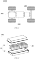
Fig. 1 is a schematic diagram of a vehicle according to some embodiments of the present application; -
Fig. 2 is an explosive view of a battery according to some embodiments of the present application; -
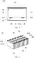
Fig. 3 is a cross-section diagram of a battery according to some embodiments of the present application; -
Fig. 4 is a structural schematic diagram of the cooperation between a bus component and a battery pack according to some embodiments of the present application; and -
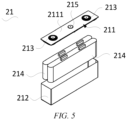
Fig. 5 is an explosive view of a battery cell according to some embodiments of the present application. -
- 1000. vehicle;
- 100. battery; 200. controller; 300. motor;
- 10. box body; 11. first portion; 12. second portion; 13. accommodating cavity; 14. infiltration space;
- 20. battery pack; 21. battery cell; 211. end cap; 2111. outer end face; 212. housing; 213. post terminal; 214. electrode assembly; 215. pressure relief mechanism; 30. bus component; 40. power output component.
- In order to make the above objectives, features and advantages of the present application more clearly understood, particular embodiments of the present application will be described in detail below with reference to the accompanying drawings. In the following description, numerous specific details are set forth in order to provide a thorough understanding of the present application. However, the present application can be implemented in many other ways different from those described herein, and those skilled in the art can make similar improvements without departing from the essence of the present application. Therefore, the present application is not limited by the particular embodiments disclosed below.
- In the description of the present application, it should be understood that the orientation or positional relationships indicated by the terms "center", "longitudinal", "transverse", "length", "width", "thickness", "upper", "lower", "front", "rear", "left", "right", "vertical", "horizontal", "top", "bottom", "inner", "outer", "clockwise", "anticlockwise", "axial", "radial", "circumferential", etc. are based on the orientation or positional relationships shown in the accompanying drawings and are merely for ease of description of the present application and simplification of the description, rather than indicating or implying that the devices or elements referred to must have a specific orientation or be constructed and operated in a described orientation, and therefore cannot be construed as limiting the present application.
- In addition, the terms "first" and "second" are used for descriptive purposes only, and cannot be construed as indicating or implying relative importance or implicitly indicating the number of technical features indicated. Therefore, the features defined with "first" and "second" may explicitly or implicitly include at least one of the features. In the description of the present application, the meaning of "a plurality of" is at least two, such as two, three and so on, unless otherwise specifically defined.
- In the present application, unless otherwise explicitly specified and defined, the terms such as "mounting", "connection", "connected" and "fixing" should be interpreted broadly, for example, either fixed or detachable connection, or integration; or may be a mechanical connection or an electrical connection; or may be a direct connection or an indirect connection through an intermediate medium, or may be internal communication between two elements or interaction between two elements, unless it may be clearly defined otherwise. For those of ordinary skill in the art, the specific meanings of the foregoing terms in the present application may be understood according to specific circumstances.
- In the present application, unless otherwise explicitly specified and defined, the expression of a first feature being "on" or "under" a second feature may be the case that the first feature is in direct contact with the second feature, or the first feature is in indirect contact with the second feature via an intermediate medium. Moreover, the first feature being "on", "above", and "over" the second feature may be the first feature being directly above or obliquely above the second feature, or simply mean that the first feature is at a higher level than the second feature. The first feature being "under", "below" and "underneath" the second feature may be the first feature being right below or obliquely below the second feature, or only means that the level height of the first feature being less than that of the second feature.
- At present, from the perspective of the development of the market situation, batteries are used more and more widely. The batteries are not only used in energy storage power systems such as hydroelectric power plants, thermal power plants, wind power plants and solar power plants, but also widely used in electric transportation means such as electric bicycles, electric motorcycles and electric vehicles and in many fields such as military equipment and aerospace. With the continuous expansion of the application field of batteries, the market demand for the batteries is also expanding.
- The inventors have noted that during an actual use process, when a battery cell in a battery undergoes thermal runaway, high-voltage ignition is easily caused, resulting in failure of a battery.
- The inventors found through intensive research that one of the reasons of high-voltage ignition of the battery is that when the battery cell undergoes thermal runaway, the conductive medium sprayed from the interior of the battery cell is easy to contact with the conductive components and overlapped between the conductive components, and/or overlapped between the conductive components and other charged components other than the conductive components to connect in series to cause high-voltage ignition, such that the safety performance of the battery is seriously reduced.
- In order to alleviate the problem of high-voltage ignition caused by the thermal runaway of the battery cell, he applicants have found through intensive research that a battery is designed, the battery comprising a box body, a battery pack, and a conductive component, wherein the box body has an accommodating cavity, the battery pack and the conductive component are both arranged in the accommodating cavity, the conductive component at least comprises at least one of the bus component, the signal transmission component, and the power output component of the battery pack, and the external part of at least one of the bus component, the signal transmission component, and the power output component is at least partially wrapped with an insulating medium. Due to the barrier effect of the insulating medium, even if a conductive medium is overlapped between the conductive components provided with the insulating medium, and/or between the conductive components provided with the insulating medium and other conductive components not provided with the insulating medium, and/or between the conductive components provided with the insulating medium and other charged components other than the conductive components, connection in series will not be formed, such that high-voltage ignition can be avoided, and the safety performance and the service life of the battery can be improved.
- The battery disclosed in the embodiments of the present application may be used in, but not limited to, a power consuming device such as a vehicle, a ship or an aircraft. A power system provided with the power consuming device composed of the battery disclosed by the present application, etc., can be used, which is conducive to reducing the risk of high-voltage ignition of the battery, and improving the safety performance and the service life of the battery.
- The embodiments of the present application provide a power consuming device using a battery as a power supply. The power consuming device may be, but is not limited to, a cell phone, a tablet, a laptop, an electric toy, an electric tool, an electric scooter, an electric vehicle, a ship, a spacecraft, etc. The electric toy may include a stationary or mobile electric toy, such as a game console, an electric vehicle toy, an electric ship toy, and an electric airplane toy. The spacecraft may include an airplane, a rocket, a space shuttle, a spaceship, etc.
- For convenience of description of the embodiments below, an embodiment in which a power consuming device according to an embodiment of the present application refers to a vehicle used for description in the following embodiments.
- Referring to
Fig. 1, Fig. 1 is a schematic structural diagram of avehicle 1000 according to some embodiments of the present application. Thevehicle 1000 may be a fuel vehicle, a gas vehicle, or a new energy vehicle. The new energy vehicle may be a battery electric vehicle, a hybrid electric vehicle, or an extended-range vehicle, etc. Abattery 100 is provided inside thevehicle 1000, and thebattery 100 may be provided at the bottom, the front or the back of thevehicle 1000. Thebattery 100 may be configured to supply power to thevehicle 1000. For example, thebattery 100 may be used as a power supply for operating thevehicle 1000. Thevehicle 1000 may further include acontroller 200 and amotor 300. Thecontroller 200 is configured to control thebattery 100 to supply power to themotor 300, for example, to meet working power requirements during starting, navigation and traveling of thevehicle 1000. - In some embodiments of the present application, the
battery 100 not only may serve as an operating power source of thevehicle 1000, but also may serve as a driving power source of thevehicle 1000, thus replacing or partially replacing fuel or natural gas to provide driving power for thevehicle 1000. - Referring to
Figs. 2 ,3 , and4 ,Fig. 2 is an explosive view of abattery 100 provided by some embodiments of the present application;Fig. 3 is a cross-section diagram of abattery 100 provided by some embodiments of the present application; andFig. 4 is a structural schematic diagram of the cooperation between abus component 30 and abattery pack 20 according to some embodiments of the present application. Thebattery 100 comprises abox body 10, abattery pack 20, and a conductive component. - The
box body 10 has anaccommodating cavity 13. Thebox body 10 is configured to provide an accommodating space for thebattery pack 20 and the conductive component, and thebox body 10 may have various structures. In some embodiments, thebox body 10 may include afirst portion 11 and asecond portion 12, thefirst portion 11 and thesecond portion 12 are fitted together in a covering manner, and thefirst portion 11 and thesecond portion 12 jointly define to form theaccommodating cavity 13. Thesecond portion 12 may be a hollow structure with one side open, thefirst portion 11 may be a plate-shaped structure, and thefirst portion 11 is fitted to the open side of thesecond portion 12 in a covered manner, such that thefirst portion 11 and thesecond portion 12 jointly define to form theaccommodating cavity 13. Thefirst portion 11 and thesecond portion 12 may also each be of a hollow structure with one side open, and the open side of thefirst portion 11 is fitted to the open side of thesecond portion 12 in a covered manner. Of course, thebox body 10 formed by thefirst portion 11 and thesecond portion 12 may have various shapes, such as a cylinder and a cuboid. - The
battery pack 20 is arranged in theaccommodating cavity 13 and comprisesseveral battery cells 21 arranged in a preset direction. One or more battery packs 20 may be provided. In some embodiments, a plurality of battery packs are provided, and thebattery 100 provided with a plurality of thebattery pack 20 has a higher energy density. In each of the battery packs 20, a plurality ofbattery cells 21 may be provided, a plurality of thebattery cells 21 may be connected in series, or connected in parallel, or connected in series and parallel to form thebattery pack 20, and all the battery packs 20 may be connected in series, or connected in parallel, or connected in series and parallel to form a battery assembly and are accommodated in theaccommodating cavity 13 of thebox body 10. - Each of
battery cells 21 may be asecondary battery 100 or aprimary battery 100; and may further be a lithium-sulfur battery 100, a sodium-ion battery 100, or a magnesium-ion battery 100, but is not limited thereto. Thebattery cell 21 may be in the shape of a cylinder, a flat body, a cuboid, etc. - Referring to
Fig. 5, Fig. 5 is an exploded view of abattery cell 21 provided by some embodiments of the present application. Thebattery cell 21 refers to the smallest unit of thebattery 100. As shown inFig. 5 , thebattery cell 21 comprises anend cap 211, ahousing 212, anelectrode assembly 214, and other functional components. - The
end cap 211 refers to a component that is fitted to an opening of thehousing 212 in a covered manner to isolate the internal environment of thebattery cell 21 from the external environment. Without limitation, the shape of theend cap 211 may be adapted to that of thehousing 212 to match thehousing 212. In some embodiments, theend cap 211 may be made of a material (for embodiment, an aluminum alloy) with a certain hardness and strength. In this way, theend cap 211 is less prone to deformation when subjected to compression and collision, such that thebattery cell 21 may have a higher structural strength and improved safety performance. A functional component, such as apost terminal 213, may be provided on theend cap 211. Thepost terminal 213 may be configured to be electrically connected to theelectrode assembly 214, so as to output or input an electric energy of thebattery cell 21. In some embodiments, theend cap 211 may further be provided with apressure relief mechanism 215 for releasing the internal pressure when the internal pressure or temperature of thebattery cell 21 reaches a threshold value. Theend cap 211 may also be made of various materials, such as copper, iron, aluminum, stainless steel, an aluminum alloy, plastic, etc., which will not be specially limited in the embodiments of the present application. - The
housing 212 is an assembly that is configured to fit with theend cap 211 so as to create the internal environment of thebattery cell 21, wherein the created internal environment may be used for accommodating theelectrode assembly 214, an electrolyte solution, and other components. Thehousing 212 and theend cap 211 may be separate components, thehousing 212 may be provided with an opening, and the internal environment of thebattery cell 21 is formed by making theend cap 211 cover the opening at the opening. Without limitation, theend cap 211 and thehousing 212 may also be integrated with each other. Specifically, theend cap 211 and thehousing 212 may form a common connection face before other components are inserted into the housing. When the interior of thehousing 212 needs to be packaged, theend cap 211 then covers thehousing 212. Thehousing 212 may have various shapes and various sizes, for example, in the form of a cuboid, a cylinder, a hexagonal prism, etc. Specifically, the shape of thehousing 212 may be determined depending on the specific shape and size of theelectrode assembly 214. Thehousing 212 may be made of various materials, such as copper, iron, aluminum, stainless steel, an aluminum alloy, plastic, etc., which is not particularly limited in the embodiments of the present application. - The
electrode assembly 214 is a component where an electrochemical reaction occurs in thebattery cell 21. Thehousing 212 may internally comprise one ormore electrode assemblies 214. Theelectrode assembly 214 is mainly formed by winding or stacking a positive electrode plate and a negative electrode plate, and a separator is generally arranged between the positive electrode plate and the negative electrode plate. The positive electrode plate and the negative electrode plate respectively both comprise a current collector and an active substance layer arranged on the current collector. The active substance layer on the positive electrode plate and the active substance layer on the negative electrode plate react with an electrolyte solution, such that charging/discharging can be achieved. - The conductive component is arranged in the
accommodating cavity 13 and comprise at least one of thebus component 30, the signal transmission component, and thepower output component 40 of thebattery pack 20. The external part of at least one of thebus component 30, the signal transmission component, and thepower output component 40 is at least partially wrapped with an insulating medium having a melting point in a range of greater than 200°C and less than or equal to 1,300°C. - The
bus component 30 of thebattery pack 20 refers to a component that achieves electrical connection betweendifferent battery cells 21 connected in series, or connected in parallel, or connected in series and parallel, such that all thebattery cells 21 located inside thebattery 100 can be connected to form a battery assembly and provide a circulation path for current. - Specifically, any two
battery cells 21 located in thesame battery pack 20 and/or two different battery packs 20 may be connected in series, in parallel, or in series and parallel via thebus components 30, and any two adjacent battery packs 20 may also be connected in series, in parallel, or in series and parallel via thebus components 30. - The
power output component 40 of thebattery pack 20 refers to a component that enables outputting current to the outside through the battery assembly formed by connecting all thebattery cells 21 in all the battery packs 20 inside thebattery 100 via thebus component 30 to output current to the outside. - For example, the
power output components 40 may be a positive electrode high-voltage output harness and/or a negative electrode high-voltage output harness. The battery assembly located inside thebattery 100 outputs current to the outside through the high-voltage output harness and/or the negative electrode high-voltage output harness. - A signal refers to other information related to the
battery cells 21 other than the current, and for example, the signal may comprise temperature information of thebattery pack 20, voltage information of thebattery pack 20, etc. Thebattery 100 is also internally provided with a signal acquisition component for acquiring signals of thebattery pack 20, and the signal acquisition component is used for acquiring a temperature signal, a voltage signal, etc. of thebattery pack 20 in thebattery 100 and transmitting the signals to a terminal. - The signal transmission component refers to a component electrically connected between the signal acquisition component and the terminal, and can transmit the signals acquired by the signal acquisition component to the terminal.
- For example, the signal transmission component may be a low-voltage harness, and the voltage of the low-voltage harness is smaller than that of the positive electrode high-voltage harness and the negative electrode high-voltage harness. The signal acquisition part located inside the
battery 100 feeds back the acquired signals to the terminal through the low-voltage harness. - The insulating medium wrapped around the external part of at least one of the
bus component 30, the signal transmission component, and thepower output component 40 is an insulating medium different from its own insulating layer. Taking the signal transmission component as the low-voltage harness as an example, the insulating medium is a member different from the insulating layer wrapped outside a bare cell of the low-voltage harness. - The insulating medium may be liquid, semi-solid, solid, etc. In some embodiments, the insulating medium is at least one of a liquid insulating medium and a semi-solid insulating medium. The liquid insulating medium and the semi-solid insulating medium have a certain adhesion and fluidity, such that the insulating medium can be conveniently coated on the conductive component, or the insulating medium can conveniently infiltrate the conductive medium, and the insulating medium is simpler to arrange. For example, the liquid insulating medium is an insulating oil.. For example, the semi-solid insulating medium is an insulating gel.
- In the present application, since the external part of at least one of the
bus component 30, the signal transmission component, and thepower output component 40 is at least partially wrapped with the insulating medium having a melting point in a range of greater than 200°C and less than or equal to 1,300°C. The insulating medium with a melting point in this range will not melt during thermal runaway. In this way, when the battery cell undergoes thermal runaway, due to the blocking effect of the insulating medium, even if the conductive medium is overlapped between the conductive components provided with the insulating medium, and/or between the conductive components provided with the insulating medium and other conductive components not provided with the insulating medium, and/or between the conductive components provided with the insulating medium and other charged components other than the conductive components, connection in series will not be formed, such that high-voltage ignition can be avoided, and the safety performance of thebattery 100 and the service life of thebattery 100 can be improved. - By referring
Figs. 2 ,3 , and5 again, in some embodiments of the present application, the conductive component comprises thebus component 30, the signal transmission component, and thepower output component 40, wherein the voltages of thebus component 30 and the signal transmission component are both less than the voltage of thepower output component 40, and the external part of at least one of thepower output component 40, the signal transmission component, and thebus component 30 are completely wrapped with the insulating medium. - Specifically, any two
adjacent battery cells 21 in thesame battery pack 20 are electrically connected via thebus component 30, output ends of all the battery packs 20 are all electrically connected to thepower output components 40, thebattery 100 further comprises a signal acquisition component arranged on thebattery pack 20, and the signal transmission component is electrically connected between the signal acquisition component and the terminal. - The
bus component 30 is configured to provide electrical connection for circuit construction inside thebattery pack 20, and thebus component 30 is generally a metal sheet. A plurality of thebus components 30 are provided, and the specific number can be determined according to the total number of thebattery cells 21. In thesame battery pack 20 and/or in different battery packs 20, thepost terminals 213 of any twobattery cells 21 can be electrically connected via thebus component 30. - The
power output component 40 is configured to provide an electrical connection for circuit output of thebattery cells 21. Thepower output components 40 may comprise two harnesses, namely the positive electrode high-voltage harness and the negative electrode high-voltage harness. The positive electrode high-voltage harness is electrically connected to a positive electrode output end of the battery assembly, and the negative electrode high-voltage harness is electrically connected to a negative electrode output end of the battery assembly to form a path for a high-voltage current to flow. - The signal transmission component is configured to provide an electrical connection for signal transmission of the
battery pack 20 and are generally a wire. Each of signal acquisition components is electrically connected with the terminal via the signal transmission component so as to feed back the acquired signals to the terminal. The number of the signal transmission components is set in one-to-one correspondence according to the number of the signal acquisition components. - Specifically, the voltages of the positive electrode high-voltage harness and the negative electrode high-voltage harness are both high voltages, while the voltages of each of the
bus components 30 and each of signal transmission components are all low voltages. - In some cases, when the
battery cells 21 undergo thermal runaway, since the sprayed conductive medium has a high temperature, the respective external insulating layers on thepower output components 40 and the signal transmission components are easily melted at a high temperature, resulting in that the bare cells of the power output components and the signal transmission components are exposed inside thebox body 10. When the conductive medium is overlapped between the bare cells of thepower output components 40 and the bare cells of the signal transmission components, and/or overlapped between the bare cells of thepower output components 40 and thebus components 30, it is likely to cause high voltage to form on thebus components 30 and the signal transmission components to cause high-voltage ignition. - In the present application, the external part of at least one of the
power output component 40, the signal transmission component, and thebus component 30 is completely wrapped with the insulating medium. Therefore, even if the insulating layer outside thepower output component 40 and/or the signal transmission component is melted, the exposed bare cell is also protected by the insulating medium, so as to prevent the conductive medium from being overlapped between the bare cell of thepower output component 40 and the bare cell of the signal transmission component and/or being overlapped between the bare cell of thepower output component 40 and thebus component 30 to cause high-voltage ignition, such that thebattery 100 has a better safety performance. - In some embodiments of the present application, the external parts of the
bus components 30, thepower output components 40, and the signal transmission components are completely wrapped with the insulating medium. - Specifically, the external parts of all the
bus components 30, all thepower output components 40, and all the signal transmission components are all wrapped with the insulating medium. Any two of thebus components 30, thepower output components 40, and the signal transmission components may be electrically isolated by the insulating medium. - With this design, even if the conductive medium is overlapped between any two of the
bus component 30, thepower output component 40, and the signal transmission component, electrical conduction between any two of thebus component 30, thepower output component 40, and the signal transmission component cannot be achieved, such that high-voltage ignition can be avoided. - In some embodiments of the present application, the
battery pack 20 comprisesseveral battery cells 21 arranged in a preset direction; each of thebattery cells 21 has anouter end face 2111 provided with apost terminal 213; and theouter end face 2111 of each of thebattery cells 21 is laid with the insulating medium. - It can be understood that the
outer end face 2111 refers to an end face of theend cap 211 facing away from thehousing 212 in thebattery cell 21. Thepost terminal 213 in eachbattery cell 21 is protrudes from theouter end face 2111, theouter end face 2111 being further provided with apressure relief mechanism 215. When thebattery cell 21 undergoes thermal runaway, the conductive medium is sprayed out of thebattery cell 21 from thepressure relief mechanism 215. - Since the
pressure relief mechanism 215 is arranged on theouter end face 2111, the sprayed conductive medium is likely to accumulate on theouter end face 2111, and overlapped between thepost terminal 213 and theouter end face 2111, such that theouter end face 2111 is charged. In addition, the conductive medium may be further overlapped between the two charged outer end faces 2111 in the twoadjacent battery cells 21 to cause the twoadjacent battery cells 21 to be connected in series. Furthermore, thebattery cells 21 connected in series continue to be connected in series via the conductive medium, such that high-voltage ignition is caused and the safety performance of thebattery 100 is reduced. - However, the outer end faces 2111 of any two
adjacent battery cells 21 are electrically isolated by the insulating medium laid on theouter end face 2111 of each of thebattery cells 21, such that the outer end faces 2111 of thebattery cells 21 can be prevented from being connected in series to cause high-voltage ignition. - In some embodiments of the present application, the outer end faces 2111 of all the
battery cells 21 are combined to form an output end face of thebattery pack 20, and aninfiltration space 14 is jointly enclosed by the output end face and inner walls of thebox body 10 facing the output end face; and thepower output components 40 and thebus components 30 are all arranged in theinfiltration space 14, which is filled with the insulating medium is filled in theinfiltration space 14. - It can be understood that when the
power output components 40 and thebus components 30 are all in infiltrated in theinfiltration space 14, and thepressure relief mechanism 215 and thepost terminal 213 of each of thebattery cells 21 are also infiltrated in theinfiltration space 14. In addition, the output end face and thepost terminal 213 are also infiltrated in the space. - With this design, the
post terminals 213, the conductive medium sprayed by means of apressure relief mechanism 215, thepower output component 40, and thebus component 30 can be wrapped by the insulating medium to prevent the conductive medium from being overlapped between thepost terminal 213 and theouter end face 2111, and/or overlapped between the bare cell of thepower output component 40 and thebus component 30, and/or overlapped between thepower output component 40 and the bare cell of the signal transmission component, so as to avoid the overlapping of the conductive medium to cause high-voltage ignition. - In some embodiments of the present application, the mass of the
battery 100 is Gi, and the mass of the insulating medium is G2, G2 meeting the following condition: G2 ≤ 0.1 G1. - In the
battery 100, the larger the mass proportion of a fire extinguishing agent, the smaller the mass proportion of the battery assembly that can be configured to supply energy, and then the lower the energy density of thebattery 100 per unit mass. - By setting G2to meet the following condition: G2 ≤ 0.1 G1, on the premise of ensuring that the
battery 100 has a higher energy density, the electric isolation between the conductive components can be realized, which is conducive to improvement in the working reliability of thebattery cells 21. - In some embodiments of the present application, G2 meets the following condition: G2 ≤ 0.01 G1.
- It is understood that the smaller the mass proportion of the insulating medium, the higher the energy density of the
battery 100. - By setting G2≤ 0.01 G1, the high energy density of the
battery 100 can be ensured while meeting the demand for electric isolation. - In some embodiments of the present application, the volume of the
battery 100 is V1, and the volume of the insulating medium is V2, V2 meeting the following condition: V2 ≤ 0.25 V1. - It can be appreciated that in the
battery 100, the greater the volume proportion of the fire extinguishing agent, the smaller the volume proportion of the battery assembly that can be configured to supply energy, and then the lower the energy density of thebattery 100 per unit mass. - By setting G2 to meet the following condition: V2 ≤ 0.25 V1, on the premise of ensuring that the
battery 100 has a higher energy density, the electric isolation between the conductive components can be achieved, which is conducive to improvement in the safety performance of thebattery cells 21. - In some embodiments of the present application, V2 meets the following condition: V2 ≤ 0.1V1.
- It is understood that the smaller the volume proportion of the insulating medium, the higher the energy density of the
battery 100. - By setting V2 ≤ 0.1 V1, the high energy density of the
battery 100 can be ensured while meeting the demand for electric isolation. - In some embodiments of the present application, the insulating medium has a melting point in a range of greater than 250°C and less than or equal to 700°C.
- During working, due to a higher internal temperature of the
battery 100 , the insulating medium should have a higher melting point in order to avoid the abnormality caused by melting or deformation of the insulating medium.. - By setting the melting point range of the insulating medium to be within the range of greater than 250°C and less than or equal to 700°C, it can be ensured that the insulating medium can still be wrapped around the external part of at least one of the
bus component 30, the signal transmission component, and thepower output component 40 of thebattery pack 20 during the working of thebattery 100, thereby ensuring the reliability of the electric isolation. In addition, the insulating medium having a melting point within this range further has a low manufacturing cost, which is conducive to reduction in a production cost of thebattery 100. - In some embodiments of the present application, the insulating medium may be a halogenated alkane,
such as at least one oftrifluoroiodomethane, perfluoropropane, perfluorobutane, perfluorohexane, pentafluoroethane, 2-hydroheptafluoropropane, trifluoromethane, and hexafluoropropane. - The halogenated alkane has an excellent thermal stability and a low price, thereby contributing to reducing a manufacturing cost of the
battery 100. - In some embodiments of the present application, the insulating medium may also be an inorganic substance, such as at least one of strontium titanate, tin oxide, cerium oxide, magnesium oxide, nickel oxide, calcium oxide, zinc oxide, zirconium dioxide, silicon dioxide, yttrium oxide, aluminium oxide, aluminum oxyhydroxide, aluminum hydroxide, titanium dioxide, silicon carbide, barium titanate, hafnium dioxide, magnesium hydroxide, and barium sulfate.
- In some embodiments of the present application, the insulating medium may also be an organic substance, such as at least one of a phenolic resin, aramid fibers, a polycarbonate plastic, polyurethane, a transformer oil, a cable oil, a capacitor oil, a natural mineral oil, a silicone oil, and trichlorobiphenyl.
- According to some embodiments of the present application, the present application further provides a power consuming device comprising the
battery 100 according to any one of the above solutions. Thebattery 100 is configured to supply electric energy to the power consuming device. - The power consuming device may be any one of the foregoing devices or systems provided with the
battery 100. - According to some embodiments of the present application, referring
Figs. 3 and 4 , the present application provides abattery 100, wherein thebattery 100 comprises abox body 10, abattery pack 20, and conductive components. Thebox body 10 has anaccommodating cavity 13, thebattery pack 20 and the conductive components are all arranged in theaccommodating cavity 13, wherein the conductive components comprise three types of abus component 30, a signal transmission component, and apower output component 40 of thebattery pack 20, and the external parts of thebus component 30, the signal transmission component, and thepower output component 40 are completely wrapped with an insulating medium having a melting point in a range of greater than 200°C and less than or equal to 1,300°C. In this way, even if the conductive medium is overlapped between any two of thebus component 30, thepower output component 40, and the signal transmission component, the electrical conduction between any two of thebus component 30, thepower output component 40, and the signal transmission component cannot be achieved, such that high-voltage ignition can be avoided. - The various technical features of the above embodiments can be combined in any manner, and in order to simplify the description, not all possible combinations of the various technical features of the above embodiments are described. However, the technical features should be considered to be within the scope of the description in the description, as long as there is no conflict between the combinations of the technical features.
- The embodiments described above merely illustrate several implementations of the present application and are described relatively specifically and in detail, but should not be construed as limiting the patent scope of the present application. It should be noted that those of ordinary skill in the art can make some variations and improvements without departing from the concept of the present application, and the variations and improvements fall within the scope of protection of the present application.
Claims (12)
- A battery, comprising:a box body (10) internally having an accommodating cavity (13);a battery pack (20) arranged in the accommodating cavity (13); anda conductive component arranged in the accommodating cavity (13) and comprising at least one of a bus component (30), a signal transmission component, and a power output component (40) of the battery pack (20), whereinthe external part of at least one of the bus component (30), the signal transmission component, and the power output component (40) is at least partially wrapped with an insulating medium having a melting point in a range of greater than 200°C and less than or equal to 1,300°C.
- The battery according to claim 1, wherein the conductive component comprises the bus component (30), the signal transmission component, and the power output component (40), wherein the voltages on the bus component (30) and the signal transmission component are both less than the voltage on the power output component (40), and
the external part of at least one of the power output component (40), the signal transmission component, and the bus component (30) is completely wrapped with the insulating medium. - The battery according to claim 2, wherein the external parts of the power output component (40), the signal transmission component, and the bus component (30) are completely wrapped with the insulating medium.
- The battery according to any one of claims 1-3, wherein the battery pack (20) comprise several battery cells (21) arranged in a preset direction;
each of the battery cells (21) has an outer end face (2111) provided with a post terminal (213); and the outer end face (2111) of each of the battery cells (21) is laid with the insulating medium. - The battery according to claim 4, wherein the outer end faces (2111) of all the battery cells (21) are combined to form an output end face of the battery pack (20), and an infiltration space (14) is jointly enclosed by the output end face and the inner wall of the box body (10) facing the output end face; and
the power output component (40) and the bus component (30) are both arranged in the infiltration space (14), which is filled with the insulating medium. - The battery according to any one of claims 1-5, wherein the mass of the battery is Gi, and the mass of the insulating medium is G2, G2 meeting the following condition: G2 ≤ 0.1 G1.
- The battery according to claim 6, wherein G2 meets the following condition: G2 ≤ 0.01 G1.
- The battery according to any one of claims 1-7, wherein the volume of the battery is V1, and the volume of the insulating medium is V2, V2 meeting the following condition: V2 ≤ 0.25 V1.
- The battery according to claim 8, wherein V2 meets the following condition: V2 ≤ 0.1 V1.
- The battery according to any one of claims 1-9, wherein the insulating medium has a melting point in a range of greater than 250°C and less than or equal to 700°C.
- The battery according to any one of claims 1-10, wherein the insulating medium is a halogenated alkane.
- A power consuming device, comprising the battery according to any one of claims 1-11, the battery being configured to supply electric energy to the power consuming device.
Applications Claiming Priority (2)
| Application Number | Priority Date | Filing Date | Title |
|---|---|---|---|
| CN202221567434.6U CN217468723U (en) | 2022-06-22 | 2022-06-22 | Batteries and Electrical Devices |
| PCT/CN2022/113048 WO2023245844A1 (en) | 2022-06-22 | 2022-08-17 | Battery and electric apparatus |
Publications (2)
| Publication Number | Publication Date |
|---|---|
| EP4395058A1 true EP4395058A1 (en) | 2024-07-03 |
| EP4395058A4 EP4395058A4 (en) | 2025-07-09 |
Family
ID=83239341
Family Applications (1)
| Application Number | Title | Priority Date | Filing Date |
|---|---|---|---|
| EP22947585.0A Pending EP4395058A4 (en) | 2022-06-22 | 2022-08-17 | Battery and electric apparatus |
Country Status (4)
| Country | Link |
|---|---|
| US (1) | US20240266699A1 (en) |
| EP (1) | EP4395058A4 (en) |
| CN (1) | CN217468723U (en) |
| WO (1) | WO2023245844A1 (en) |
Family Cites Families (9)
| Publication number | Priority date | Publication date | Assignee | Title |
|---|---|---|---|---|
| KR20150143060A (en) * | 2014-06-13 | 2015-12-23 | 주식회사 메가테크 | Bus bar united by covering member |
| CN105977521B (en) * | 2016-05-06 | 2018-09-28 | 中国船舶重工集团公司第七一二研究所 | A kind of high security lithium ion battery |
| KR102780571B1 (en) * | 2019-08-12 | 2025-03-11 | 주식회사 엘지에너지솔루션 | A bus bar with excellent insulation and heat dissipation performance and battery module with same |
| CN111129412B (en) * | 2020-03-31 | 2020-12-29 | 江苏时代新能源科技有限公司 | Connecting assembly, battery module, device, and method for manufacturing connecting assembly |
| CN112332032B (en) * | 2020-06-23 | 2024-02-23 | 宁德时代新能源科技股份有限公司 | Battery pack and device using battery pack as power supply |
| EP3958387B1 (en) * | 2020-07-10 | 2023-06-21 | Contemporary Amperex Technology Co., Limited | Battery and related apparatus thereof, preparation method therefor, and preparation device therefor |
| CN111952515B (en) * | 2020-10-19 | 2021-02-02 | 江苏时代新能源科技有限公司 | Battery, electric device, and method and device for preparing battery |
| CN214411453U (en) * | 2021-01-21 | 2021-10-15 | 江苏塔菲尔动力系统有限公司 | Battery module and battery package of solar heat protection diffusion |
| EP4047728A1 (en) * | 2021-02-17 | 2022-08-24 | Samsung SDI Co., Ltd. | Battery system and vehicle including the battery system |
-
2022
- 2022-06-22 CN CN202221567434.6U patent/CN217468723U/en active Active
- 2022-08-17 EP EP22947585.0A patent/EP4395058A4/en active Pending
- 2022-08-17 WO PCT/CN2022/113048 patent/WO2023245844A1/en not_active Ceased
-
2024
- 2024-04-18 US US18/638,745 patent/US20240266699A1/en active Pending
Also Published As
| Publication number | Publication date |
|---|---|
| US20240266699A1 (en) | 2024-08-08 |
| EP4395058A4 (en) | 2025-07-09 |
| CN217468723U (en) | 2022-09-20 |
| WO2023245844A1 (en) | 2023-12-28 |
Similar Documents
| Publication | Publication Date | Title |
|---|---|---|
| EP4425654A1 (en) | Battery cell, battery and electric device | |
| EP4333172A1 (en) | Battery cell, battery, electrical device, and method and device for fabricating battery cell | |
| CN115036643B (en) | Battery monomer, battery and consumer | |
| EP4730533A1 (en) | Battery cell, battery, and electric device | |
| EP4560798A1 (en) | Top cover assembly, battery cell, battery, and electric apparatus | |
| EP4675730A1 (en) | Battery, electric device and energy storage device | |
| CN115084733B (en) | Shell, battery cell, battery and electrical device | |
| US12609383B2 (en) | Casing assembly, battery cell, battery, and electric apparatus | |
| CN116470241A (en) | Electrode components, battery cells, batteries and electrical equipment | |
| US20230361356A1 (en) | Battery unit, and battery, power consuming device and preparation apparatus associated therewith | |
| WO2023142064A1 (en) | Battery cell, battery, electric device, and method and device for manufacturing battery cell | |
| EP4510332A1 (en) | Battery cell, battery and electrical device | |
| EP4395058A1 (en) | Battery and electric apparatus | |
| US20240363976A1 (en) | Connecting assembly, battery cell, battery, and power consumption device | |
| WO2023050245A1 (en) | Adapter component, battery cell, battery, electric device, and method and device for manufacturing battery cell | |
| CN222126920U (en) | Batteries, battery modules, battery packs, energy storage devices and power consumption devices | |
| EP4350816A1 (en) | Battery cell, battery, and power consuming device | |
| EP4280359A1 (en) | Battery, battery module and electric energy apparatus | |
| CN217114528U (en) | Sampling assembly, battery and electric device | |
| CN116670919A (en) | Battery cell, battery, electrical device, and battery cell manufacturing method and manufacturing equipment | |
| CN115911255A (en) | End cover assembly, battery monomer, battery and power consumption device | |
| EP4451437A1 (en) | Top cover assembly, battery cell, battery, and electrical device | |
| CN115882135B (en) | Battery cell, battery, electrical equipment, method and equipment for manufacturing battery cell | |
| CN118783002B (en) | Battery devices and power-consuming devices | |
| CN220420607U (en) | Battery monomer, battery and power consumption device |
Legal Events
| Date | Code | Title | Description |
|---|---|---|---|
| STAA | Information on the status of an ep patent application or granted ep patent |
Free format text: STATUS: THE INTERNATIONAL PUBLICATION HAS BEEN MADE |
|
| PUAI | Public reference made under article 153(3) epc to a published international application that has entered the european phase |
Free format text: ORIGINAL CODE: 0009012 |
|
| STAA | Information on the status of an ep patent application or granted ep patent |
Free format text: STATUS: REQUEST FOR EXAMINATION WAS MADE |
|
| 17P | Request for examination filed |
Effective date: 20240325 |
|
| AK | Designated contracting states |
Kind code of ref document: A1 Designated state(s): AL AT BE BG CH CY CZ DE DK EE ES FI FR GB GR HR HU IE IS IT LI LT LU LV MC MK MT NL NO PL PT RO RS SE SI SK SM TR |
|
| RAP1 | Party data changed (applicant data changed or rights of an application transferred) |
Owner name: CONTEMPORARY AMPEREX TECHNOLOGY(HONG KONG) LIMITED |
|
| A4 | Supplementary search report drawn up and despatched |
Effective date: 20250606 |
|
| RIC1 | Information provided on ipc code assigned before grant |
Ipc: H01M 50/502 20210101ALI20250602BHEP Ipc: H01M 50/588 20210101ALI20250602BHEP Ipc: H01M 50/593 20210101AFI20250602BHEP |
|
| DAV | Request for validation of the european patent (deleted) | ||
| DAX | Request for extension of the european patent (deleted) |