EP4395050A1 - Battery cell, battery, and electric device - Google Patents
Battery cell, battery, and electric device Download PDFInfo
- Publication number
- EP4395050A1 EP4395050A1 EP22948992.7A EP22948992A EP4395050A1 EP 4395050 A1 EP4395050 A1 EP 4395050A1 EP 22948992 A EP22948992 A EP 22948992A EP 4395050 A1 EP4395050 A1 EP 4395050A1
- Authority
- EP
- European Patent Office
- Prior art keywords
- electrode terminal
- connecting component
- welding
- battery cell
- thinned region
- Prior art date
- Legal status (The legal status is an assumption and is not a legal conclusion. Google has not performed a legal analysis and makes no representation as to the accuracy of the status listed.)
- Pending
Links
Images



Classifications
-
- H—ELECTRICITY
- H01—ELECTRIC ELEMENTS
- H01M—PROCESSES OR MEANS, e.g. BATTERIES, FOR THE DIRECT CONVERSION OF CHEMICAL ENERGY INTO ELECTRICAL ENERGY
- H01M50/00—Constructional details or processes of manufacture of the non-active parts of electrochemical cells other than fuel cells, e.g. hybrid cells
- H01M50/50—Current conducting connections for cells or batteries
- H01M50/531—Electrode connections inside a battery casing
- H01M50/533—Electrode connections inside a battery casing characterised by the shape of the leads or tabs
-
- H—ELECTRICITY
- H01—ELECTRIC ELEMENTS
- H01M—PROCESSES OR MEANS, e.g. BATTERIES, FOR THE DIRECT CONVERSION OF CHEMICAL ENERGY INTO ELECTRICAL ENERGY
- H01M50/00—Constructional details or processes of manufacture of the non-active parts of electrochemical cells other than fuel cells, e.g. hybrid cells
- H01M50/10—Primary casings; Jackets or wrappings
- H01M50/102—Primary casings; Jackets or wrappings characterised by their shape or physical structure
- H01M50/103—Primary casings; Jackets or wrappings characterised by their shape or physical structure prismatic or rectangular
-
- H—ELECTRICITY
- H01—ELECTRIC ELEMENTS
- H01M—PROCESSES OR MEANS, e.g. BATTERIES, FOR THE DIRECT CONVERSION OF CHEMICAL ENERGY INTO ELECTRICAL ENERGY
- H01M50/00—Constructional details or processes of manufacture of the non-active parts of electrochemical cells other than fuel cells, e.g. hybrid cells
- H01M50/50—Current conducting connections for cells or batteries
- H01M50/531—Electrode connections inside a battery casing
- H01M50/536—Electrode connections inside a battery casing characterised by the method of fixing the leads to the electrodes, e.g. by welding
-
- H—ELECTRICITY
- H01—ELECTRIC ELEMENTS
- H01M—PROCESSES OR MEANS, e.g. BATTERIES, FOR THE DIRECT CONVERSION OF CHEMICAL ENERGY INTO ELECTRICAL ENERGY
- H01M50/00—Constructional details or processes of manufacture of the non-active parts of electrochemical cells other than fuel cells, e.g. hybrid cells
- H01M50/50—Current conducting connections for cells or batteries
- H01M50/543—Terminals
- H01M50/547—Terminals characterised by the disposition of the terminals on the cells
- H01M50/55—Terminals characterised by the disposition of the terminals on the cells on the same side of the cell
-
- H—ELECTRICITY
- H01—ELECTRIC ELEMENTS
- H01M—PROCESSES OR MEANS, e.g. BATTERIES, FOR THE DIRECT CONVERSION OF CHEMICAL ENERGY INTO ELECTRICAL ENERGY
- H01M50/00—Constructional details or processes of manufacture of the non-active parts of electrochemical cells other than fuel cells, e.g. hybrid cells
- H01M50/50—Current conducting connections for cells or batteries
- H01M50/543—Terminals
- H01M50/552—Terminals characterised by their shape
- H01M50/553—Terminals adapted for prismatic, pouch or rectangular cells
-
- H—ELECTRICITY
- H01—ELECTRIC ELEMENTS
- H01M—PROCESSES OR MEANS, e.g. BATTERIES, FOR THE DIRECT CONVERSION OF CHEMICAL ENERGY INTO ELECTRICAL ENERGY
- H01M50/00—Constructional details or processes of manufacture of the non-active parts of electrochemical cells other than fuel cells, e.g. hybrid cells
- H01M50/50—Current conducting connections for cells or batteries
- H01M50/543—Terminals
- H01M50/564—Terminals characterised by their manufacturing process
- H01M50/566—Terminals characterised by their manufacturing process by welding, soldering or brazing
-
- B—PERFORMING OPERATIONS; TRANSPORTING
- B60—VEHICLES IN GENERAL
- B60R—VEHICLES, VEHICLE FITTINGS, OR VEHICLE PARTS, NOT OTHERWISE PROVIDED FOR
- B60R16/00—Electric or fluid circuits specially adapted for vehicles and not otherwise provided for; Arrangement of elements of electric or fluid circuits specially adapted for vehicles and not otherwise provided for
- B60R16/02—Electric or fluid circuits specially adapted for vehicles and not otherwise provided for; Arrangement of elements of electric or fluid circuits specially adapted for vehicles and not otherwise provided for electric constitutive elements
- B60R16/03—Electric or fluid circuits specially adapted for vehicles and not otherwise provided for; Arrangement of elements of electric or fluid circuits specially adapted for vehicles and not otherwise provided for electric constitutive elements for supply of electrical power to vehicle subsystems or for
- B60R16/033—Electric or fluid circuits specially adapted for vehicles and not otherwise provided for; Arrangement of elements of electric or fluid circuits specially adapted for vehicles and not otherwise provided for electric constitutive elements for supply of electrical power to vehicle subsystems or for characterised by the use of electrical cells or batteries
-
- H—ELECTRICITY
- H01—ELECTRIC ELEMENTS
- H01M—PROCESSES OR MEANS, e.g. BATTERIES, FOR THE DIRECT CONVERSION OF CHEMICAL ENERGY INTO ELECTRICAL ENERGY
- H01M2220/00—Batteries for particular applications
- H01M2220/20—Batteries in motive systems, e.g. vehicle, ship, plane
-
- Y—GENERAL TAGGING OF NEW TECHNOLOGICAL DEVELOPMENTS; GENERAL TAGGING OF CROSS-SECTIONAL TECHNOLOGIES SPANNING OVER SEVERAL SECTIONS OF THE IPC; TECHNICAL SUBJECTS COVERED BY FORMER USPC CROSS-REFERENCE ART COLLECTIONS [XRACs] AND DIGESTS
- Y02—TECHNOLOGIES OR APPLICATIONS FOR MITIGATION OR ADAPTATION AGAINST CLIMATE CHANGE
- Y02E—REDUCTION OF GREENHOUSE GAS [GHG] EMISSIONS, RELATED TO ENERGY GENERATION, TRANSMISSION OR DISTRIBUTION
- Y02E60/00—Enabling technologies; Technologies with a potential or indirect contribution to GHG emissions mitigation
- Y02E60/10—Energy storage using batteries
Definitions
- This application pertains to the field of battery technologies, and in particular relates to a battery cell, a battery, and an electric apparatus.
- Battery cells are systems that can be combined with each other to utilize new renewable energy.
- the connecting components are not tightly connected to the electrode terminals, which affects the energy density and cycle life of the battery.
- a battery cell including a housing, an electrode terminal, an electrode assembly, and a connecting component.
- the electrode terminal is provided on the housing, and the electrode assembly is accommodated in the housing.
- the connecting component is configured to connect the electrode terminal and the electrode assembly.
- the connecting component includes a first connecting portion for connecting the electrode terminal, where the first connecting portion includes a main body region and a thinned region, the thinned region having a smaller thickness than the main body region, and at least part of the thinned region being used for welding to the electrode terminal.
- At least part of the thinned region is used for welding to the electrode terminal and forming a first welding portion, and at least part of the main body region is used for welding to the electrode terminal and forming a second welding portion.
- the first connecting portion is laser welded to the electrode terminal.
- the connecting component is further provided with a first concave portion, where the first concave portion is recessed from a surface of the connecting component away from the electrode terminal, and the thinned region corresponds to a bottom surface of the first concave portion.
- the connecting component is further provided with a second connecting portion, a convex portion, and a second concave portion, where the second connecting portion is configured to connect the electrode assembly; the convex portion protrudes from a surface of the connecting component towards the electrode terminal; and a position of the second concave portion corresponds to the convex portion in a thickness direction of the connecting component, and the second concave portion is recessed from the surface of the connecting component away from the electrode terminal and extends into the convex portion.
- the provision of the second connecting portion allows the connecting component to connect the electrode assembly; the provision of the convex portion enables the connecting component to fit more closely to the electrode terminal, improving the welding stability of the connecting component and the electrode terminal; and the provision of the second concave portion makes the convex portion a cavity structure, and reduces the thickness at the convex portion, facilitating the welding of the convex portion to the electrode terminal.
- the areas of the first connecting portion and the thinned region are limited to ensure an appropriate proportion of the thinned region within the first connecting portion, thus improving the strength of the connection. This can also prevent the thinned region from taking up an excessively large proportion, thus avoiding a decrease in the mechanical strength and current-carrying capacity at the first connecting portion of the connecting component.
- the thinned region is provided so that the thickness at the thinned region is reduced. This allows for a greater depth of fusion at the thinned region after the connecting component is welded to the electrode terminal, achieving a more stable connection between the connecting component and the electrode terminal, and preventing the connecting component from separating from the electrode terminal.
- the greater depth of fusion at the thinned region can also reduce the problem of incomplete welds between the connecting component and the electrode terminal, preventing an increase in contact resistance between the connecting component and the electrode terminal caused by incomplete welds. This in turn improves the consistency of the battery cell during the charging and discharging processes, improves the energy density and cycle life of the battery cell, and enhances the use safety of the battery cell.
- the inventors have found that the structure of the portion of the connecting component on which the electrode terminal is welded can be adjusted to increase the depth of fusion during welding of the connecting component to the electrode terminal without adjusting the welding conditions. This not only enhances the connection stability and welding strength after the welding, but also promotes the connection between the connecting component and the electrode terminal and reduces the occurrence of missing welds, thus improving the energy density, cycle life, and use safety of the battery.
- An embodiment of this application provides an electric apparatus that uses a battery as a power source.
- the electric apparatus may be but is not limited to a mobile phone, a tablet, a laptop computer, an electric toy, an electric tool, an electric bicycle, an electric car, a ship, or a spacecraft.
- the electric toy may be a fixed or mobile electric toy, for example, a game console, an electric toy car, an electric toy ship, or an electric toy airplane.
- the spacecraft may include an airplane, a rocket, a space shuttle, a spaceship, and the like.
- the electric apparatus of an embodiment of this application being a vehicle 1000 is used as an example for description of the following embodiments.
- FIG. 2 is a schematic structural diagram of a battery 100 according to some embodiments of this application.
- the battery 100 includes a box 110.
- the box 110 may include a first box portion 111 and a second box portion 112 that are connected to each other, and a plurality of battery cells are connected in parallel, series, or series-parallel, and then put into the space formed after the first box portion 111 and the second box portion 112 are connected.
- the shapes of the first box portion 111 and the second box portion 112 may be determined based on the shape of the plurality of battery cells combined.
- the battery cell may be cylindrical, flat, cuboid, or of other shapes, which is not limited in the embodiments of this application.
- the area of the thinned region 101 is D2 and the area of the first connecting portion 10 is D3, where 0.3 ⁇ D2/D3 ⁇ 0.4.
- At least part of the thinned region 101 is used for welding to the electrode terminal 123 and forming a first welding portion 103, and at least part of the main body region 102 is used for welding to the electrode terminal 123 and forming a second welding portion 104.
- the first welding portion 103 and the second welding portion 104 are connected as one entity, and the first connecting portion 10 is laser welded to the electrode terminal 123.
- the connecting component 140 is further provided with a first concave portion 1, where the first concave portion 1 is recessed from a surface of the connecting component 140 away from the electrode terminal 123, and the thinned region 101 corresponds to a bottom surface of the first concave portion 1.
- This test example is substantially the same as Comparative Example 1, except that the welding power is 4.2 KW.
Landscapes
- Chemical & Material Sciences (AREA)
- Chemical Kinetics & Catalysis (AREA)
- Electrochemistry (AREA)
- General Chemical & Material Sciences (AREA)
- Engineering & Computer Science (AREA)
- Manufacturing & Machinery (AREA)
- Connection Of Batteries Or Terminals (AREA)
- Sealing Battery Cases Or Jackets (AREA)
- Battery Mounting, Suspending (AREA)
Abstract
Description
- This application claims priority to
Chinese patent application 202210734115.8, filed on June 27, 2022 - This application pertains to the field of battery technologies, and in particular relates to a battery cell, a battery, and an electric apparatus.
- With the increasing consumption of natural resources and damage to the environment, there is a growing interest in various fields in apparatuses that can store energy and efficiently utilize the stored energy. Battery cells are systems that can be combined with each other to utilize new renewable energy.
- In the field of battery device technology, the connecting components are not tightly connected to the electrode terminals, which affects the energy density and cycle life of the battery.
- Embodiments of this application provide a battery cell, a battery, and an electric apparatus, so as to improve stability at the connecting components and increase the energy density and cycle life of the battery.
- According to a first aspect of the embodiments of this application, a battery cell is provided, including a housing, an electrode terminal, an electrode assembly, and a connecting component. The electrode terminal is provided on the housing, and the electrode assembly is accommodated in the housing. The connecting component is configured to connect the electrode terminal and the electrode assembly. The connecting component includes a first connecting portion for connecting the electrode terminal, where the first connecting portion includes a main body region and a thinned region, the thinned region having a smaller thickness than the main body region, and at least part of the thinned region being used for welding to the electrode terminal.
- With the above structure, through provision of the thinned region, the thickness at the thinned region is reduced. This allows for a greater depth of fusion at the thinned region after the connecting component is welded to the electrode terminal, achieving a more stable connection between the connecting component and the electrode terminal, and preventing the connecting component from separating from the electrode terminal. The greater depth of fusion at the thinned region can also reduce the problem of incomplete welds between the connecting component and the electrode terminal, preventing an increase in contact resistance between the connecting component and the electrode terminal caused by incomplete welds. This in turn improves the consistency of the battery cell during the charging and discharging processes, improves the energy density and cycle life of the battery cell, and enhances the use safety of the battery cell.
- In some embodiments of this application, at least part of the thinned region is used for welding to the electrode terminal and forming a first welding portion, and at least part of the main body region is used for welding to the electrode terminal and forming a second welding portion.
- With the above structure, the provision of the first welding portion and the second welding portion allows both the main body region and thinned region on the first connecting portion to be welded to the electrode terminal, improving the stability of the connection between the connecting component and the electrode terminal.
- In some embodiments of this application, the first welding portion and the second welding portion are connected as one entity.
- With the above structure, the first welding portion and the second welding portion are connected as one entity, which can improve the overall integrity of the weld part, making the connection between the connecting component and the electrode terminal more stable.
- In some embodiments of this application, the first connecting portion is laser welded to the electrode terminal.
- With the above structure, the first connecting portion is laser welded to the electrode terminal, which can improve the depth of fusion of the thinned region during welding, and improve the strength of the connection between the first connecting portion and the electrode terminal.
- In some embodiments of this application, the connecting component is further provided with a first concave portion, where the first concave portion is recessed from a surface of the connecting component away from the electrode terminal, and the thinned region corresponds to a bottom surface of the first concave portion.
- With the above structure, provision of the first concave portion facilitates the formation of the thinned region and allows the thinned region to be integrally formed with the main body region, improving the integrity of the connecting component.
- In some embodiments of this application, the connecting component is further provided with a second connecting portion, a convex portion, and a second concave portion, where the second connecting portion is configured to connect the electrode assembly; the convex portion protrudes from a surface of the connecting component towards the electrode terminal; and a position of the second concave portion corresponds to the convex portion in a thickness direction of the connecting component, and the second concave portion is recessed from the surface of the connecting component away from the electrode terminal and extends into the convex portion.
- With the above structure, the provision of the second connecting portion allows the connecting component to connect the electrode assembly; the provision of the convex portion enables the connecting component to fit more closely to the electrode terminal, improving the welding stability of the connecting component and the electrode terminal; and the provision of the second concave portion makes the convex portion a cavity structure, and reduces the thickness at the convex portion, facilitating the welding of the convex portion to the electrode terminal.
- In some embodiments of this application, a bottom surface of the second concave portion corresponding to the convex portion includes the first connecting portion.
- With the above structure, provision of the first connecting portion on the convex portion allows the first connecting portion to protrude toward the electrode terminal, so that the first connecting portion fits on the surface of the electrode terminal, improving stability of the welding.
- In some embodiments of this application, thickness of the connecting component is L1 and depth of the first concave portion is L2, satisfying 0 < L2/L1 ≤ 0.8.
- With the above structure, limiting the thickness of the first concave portion can ensure an increased depth of fusion within the thinned region during welding. If the thickness of the thinned region is too small, the welding surface will be too far from the laser emission point, which significantly increases the defocus amount and decreases the welding strength, leading to a reduced depth of fusion. Additionally, limiting the thickness of the first concave portion can also prevent the thinned region from being too thin and melt off during welding.
- In some embodiments of this application, in a plane perpendicular to the thickness direction, the area of the second concave portion is D 1 and the area of the thinned region is D2, where 0.2 ≤ D2/D1 ≤ 0.4.
- With the above structure, the areas of the second concave portion and the thinned region are limited to ensure an appropriate proportion of the thinned region within the second concave portion, thus improving the strength of the connection.
- In some embodiments of this application, in a plane perpendicular to the thickness direction, the area of the thinned region is D2 and the area of the first connecting portion is D3, where

- With the above structure, the areas of the first connecting portion and the thinned region are limited to ensure an appropriate proportion of the thinned region within the first connecting portion, thus improving the strength of the connection. This can also prevent the thinned region from taking up an excessively large proportion, thus avoiding a decrease in the mechanical strength and current-carrying capacity at the first connecting portion of the connecting component.
- In some embodiments of this application, in a plane perpendicular to the thickness direction, the thinned region is circular.
- With the above structure, the thinned region is designed as circular so that the junction between the thinned region and the main body region is curved, which facilitates the dispersion of the force on the first connecting portion to the thinned region and the main body region, thus improving the strength of the junction between the main body region and the thinned region.
- According to a second aspect of the embodiments of this application, a battery is provided, including the foregoing battery cell.
- According to a third aspect of the embodiments of this application, an electric apparatus is provided, including the foregoing battery cell for supplying electrical energy.
- Compared with the prior art, in the battery cell, battery, and electric apparatus according to the embodiments of this application, the thinned region is provided so that the thickness at the thinned region is reduced. This allows for a greater depth of fusion at the thinned region after the connecting component is welded to the electrode terminal, achieving a more stable connection between the connecting component and the electrode terminal, and preventing the connecting component from separating from the electrode terminal. The greater depth of fusion at the thinned region can also reduce the problem of incomplete welds between the connecting component and the electrode terminal, preventing an increase in contact resistance between the connecting component and the electrode terminal caused by incomplete welds. This in turn improves the consistency of the battery cell during the charging and discharging processes, improves the energy density and cycle life of the battery cell, and enhances the use safety of the battery cell.
- The following describes features, advantages, and technical effects of the example embodiments of this application with reference to the accompanying drawings.
-
FIG. 1 is a schematic structural diagram of a vehicle according to some embodiments of this application. -
FIG. 2 is a schematic structural diagram of a battery according to some embodiments of this application; -
FIG. 3 is a schematic structural diagram of a battery cell according to some embodiments of this application; -
FIG. 4 is a schematic structural diagram of a connecting component according to some embodiments of this application; -
FIG. 5 is a schematic cross-sectional view of a connecting component according to some embodiments of this application; -
FIG. 6 is an enlarged schematic diagram of a first connecting portion inFIG. 5 ; -
FIG. 7 is a schematic structural diagram of a battery cell according to some embodiments of this application from another perspective; -
FIG. 8 is a schematic cross-sectional view along A-A inFIG. 7 ; -
FIG. 9 is an enlarged schematic diagram of position P1 inFIG. 8 ; -
FIG. 10 is a schematic structural diagram of a second concave portion according to some embodiments of this application; and -
FIG. 11 is a schematic structural diagram of a second concave portion according to some other embodiments of this application. - In the accompanying drawings:
- 1000. vehicle; 100. battery; 200. controller; 300. motor; 110. box; 111. first box portion; 112. second box portion; 120. housing; 121. end cap; 122. shell; 123. electrode terminal; 124. terminal plate; 125. fixing block; 130. electrode assembly; 140. connecting component;
- 10. first connecting portion; 101. thinned region; 102. main body region; 103. first welding portion; 104. second welding portion; 20. second connecting portion; 1. first concave portion; 2. convex portion; and 3. second concave portion.
- In the accompanying drawings, the figures are not necessarily drawn to scale.
- The following further describes the implementations of this application in detail with reference to the accompanying drawings and embodiments. The detailed description of embodiments and the accompanying drawings are intended to illustrate the principle of this application, rather than to limit the scope of this application, meaning this application is not limited to the embodiments described herein.
- In the description of this application, it should be noted that, unless otherwise stated, "multiple" means at least two; and the orientations or positional relationships indicated by the terms "upper", "lower", "left", "right", "inside", "outside", and the like are merely for ease and brevity of description of this application rather than indicating or implying that the means or components mentioned must have specific orientations or must be constructed or manipulated according to particular orientations. These terms shall therefore not be construed as limitations on this application. In addition, the terms "first", "second", "third", and the like are merely for the purpose of description and shall not be understood as any indication or implication of relative importance. "Perpendicular" is not perpendicular in the strict sense but within an allowable range of error. "Parallel" is not parallel in the strict sense but within an allowable range of error.
- Reference to "embodiment" in this application means that specific features, structures, or characteristics described with reference to the embodiment may be included in at least one embodiment of this application. The word "embodiment" appearing in various places in the specification does not necessarily refer to the same embodiment or an independent or alternative embodiment that is exclusive of other embodiments. It is explicitly or implicitly understood by persons skilled in the art that the embodiments described herein may be combined with other embodiments.
- The orientation terms appearing in the following description all are directions shown in the figures and do not limit the specific structure of the application. In the description of this application, it should also be noted that unless otherwise specified and defined explicitly, the terms "mount", "connect", and "join" should be understood in their general senses. For example, they may refer to a fixed connection, a detachable connection, or an integral connection, and may refer to a direct connection or an indirect connection via an intermediate medium. Persons of ordinary skill in the art can understand specific meanings of these terms in this application as appropriate to specific situations.
- In the development of battery technology, multiple design factors need to be considered, such as energy density, cycle life, and battery safety. These factors have become obstacles that hinder the further promotion of batteries.
- The inventors have noticed that the welding process between the connecting component and the electrode terminal is greatly affected by process variations, resulting in the problem of incomplete welds between the connecting component and the electrode terminal, such as weak or missing welding. The problem of incomplete welds increases the contact resistance between the connecting component and the electrode terminal and decreases the battery consistency during charging and discharging processes, thus affecting the energy density, cycle life, and use safety of the battery.
- To alleviate the incomplete weld problem of the battery, the inventors have found that the structure of the portion of the connecting component on which the electrode terminal is welded can be adjusted to increase the depth of fusion during welding of the connecting component to the electrode terminal without adjusting the welding conditions. This not only enhances the connection stability and welding strength after the welding, but also promotes the connection between the connecting component and the electrode terminal and reduces the occurrence of missing welds, thus improving the energy density, cycle life, and use safety of the battery.
- Based on the above considerations, the inventors of this application have designed a battery cell, a battery, and an electric apparatus after in-depth research.
- An embodiment of this application provides an electric apparatus that uses a battery as a power source. The electric apparatus may be but is not limited to a mobile phone, a tablet, a laptop computer, an electric toy, an electric tool, an electric bicycle, an electric car, a ship, or a spacecraft. The electric toy may be a fixed or mobile electric toy, for example, a game console, an electric toy car, an electric toy ship, or an electric toy airplane. The spacecraft may include an airplane, a rocket, a space shuttle, a spaceship, and the like.
- For ease of description, the electric apparatus of an embodiment of this application being a
vehicle 1000 is used as an example for description of the following embodiments. - As shown in
FIG. 1, FIG. 1 is a schematic structural diagram of avehicle 1000 according to some embodiments of this application. Thevehicle 1000 may be a fossil fuel vehicle, a natural-gas vehicle, or a new energy vehicle, where the new energy vehicle may be a battery electric vehicle, a hybrid electric vehicle, a range-extended vehicle, or the like. Thevehicle 1000 is provided with abattery 100 inside, and thebattery 100 may be disposed at the bottom, front, or rear of thevehicle 1000. Thebattery 100 may be configured to supply power to thevehicle 1000. For example, thebattery 100 may be used as an operational power source for thevehicle 1000. Thevehicle 1000 may further include acontroller 200 and amotor 300, where thecontroller 200 is configured to control thebattery 100 to supply power to themotor 300, for example, to satisfy power needs of start, navigation, and driving of thevehicle 1000. - In some embodiments of this application, the
battery 100 can be used as not only the operational power source for thevehicle 1000 but also a driving power source for thevehicle 1000, replacing or partially replacing fossil fuel or natural gas to provide driving traction for thevehicle 1000. - The battery mentioned in the embodiments of this application is a single physical module that includes one or more battery cells for providing a higher voltage and capacity. For example, the battery mentioned in this application may include a battery module, a battery pack, or the like.
- As shown in
FIG. 2, FIG. 2 is a schematic structural diagram of abattery 100 according to some embodiments of this application. In some embodiments of this application, thebattery 100 includes abox 110. Thebox 110 may include afirst box portion 111 and asecond box portion 112 that are connected to each other, and a plurality of battery cells are connected in parallel, series, or series-parallel, and then put into the space formed after thefirst box portion 111 and thesecond box portion 112 are connected. The shapes of thefirst box portion 111 and thesecond box portion 112 may be determined based on the shape of the plurality of battery cells combined. The battery cell may be cylindrical, flat, cuboid, or of other shapes, which is not limited in the embodiments of this application. In terms of packaging method, battery cells include but are not limited to cylindrical cell, prismatic cell, and pouch cell. The type of battery cells is not specifically limited in the embodiments of this application either. Thebattery 100 may further include other structures, for example, a busbar for implementing electrical connections between the plurality of battery cells. Such structures are not described herein. - As shown in
FIG. 3 to FIG. 6 ,FIG. 3 is a schematic structural diagram of a battery cell according to some embodiments of this application,FIG. 4 is a schematic structural diagram of a connectingcomponent 140 according to some embodiments of this application,FIG. 5 is a schematic cross-sectional view of a connectingcomponent 140 according to some embodiments of this application, andFIG. 6 is an enlarged schematic diagram of a first connectingportion 10 inFIG. 5 . In some embodiments of this application, a battery cell is provided, including ahousing 120, anelectrode terminal 123, anelectrode assembly 130, and a connectingcomponent 140. Theelectrode terminal 123 is provided on thehousing 120, and theelectrode assembly 130 is accommodated in thehousing 120. The connectingcomponent 140 is configured to connect theelectrode terminal 123 and theelectrode assembly 130. The connectingcomponent 140 includes a first connectingportion 10 for connecting theelectrode terminal 123. The first connectingportion 10 includes amain body region 102 and a thinnedregion 101, the thinnedregion 101 having a smaller thickness than themain body region 102, and at least part of the thinnedregion 101 being used for welding to theelectrode terminal 123. - The
housing 120 is an assembly configured to form an internal environment of the battery cell, where the formed internal environment can be used to accommodate theelectrode assembly 130, an electrolyte (not shown in the figure), and other components. Thehousing 120 may be in a variety of structural forms, such as rectangular and cylindrical. For example, the shape of thehousing 120 may be determined based on a specific shape of theelectrode assembly 130. Thehousing 120 may be made of various materials, such as copper, iron, aluminum, stainless steel, aluminum alloy, and plastic, and the materials are not particularly limited in the embodiments of this application. - Referring to
FIG. 7 to FIG. 9 ,FIG. 7 is a schematic structural diagram of a battery cell according to some embodiments of this application from another perspective.FIG. 8 is a schematic cross-sectional view along A-A inFIG. 7 .FIG. 9 is an enlarged schematic diagram of position P1 inFIG. 8 . Theelectrode terminal 123 is configured to be electrically connected to the connectingcomponent 140 and further to theelectrode assembly 130, for the power to be led out from or led into the battery cell. For example, theelectrode terminal 123 may be provided as a pole, where one end of the pole post is provided inside thehousing 120 and connected to the connectingcomponent 140, and the other end is provided outside thehousing 120. For example, theelectrode terminal 123 may be provided as aterminal plate 124, theterminal plate 124 is provided outside thehousing 120, and the connectingcomponent 140 is connected to a bottom end of theterminal plate 124. - The connecting
component 140 is configured to implement an electrical connection between theelectrode terminal 123 and theelectrode assembly 130, and the connectingcomponent 140 may be an adapter sheet. - The
electrode assembly 130 is a component in which electrochemical reactions take place in the battery cell. For example, theelectrode assembly 130 is mainly formed by winding or stacking a positive electrode plate and a negative electrode plate, and a separator is generally disposed between the positive electrode plate and the negative electrode plate. Parts of the positive electrode plate and the negative electrode plate that have active substances constitute a body portion of theelectrode assembly 130, while parts of the positive electrode plate and the negative electrode plate that have no active substances separately constitute a tab. In a charging and discharging process of the battery, a positive electrode active substance and a negative electrode active substance react with the electrolyte, and tabs are connected to theelectrode terminals 123 via the connectingcomponent 140 to form a current loop. - Through provision of the thinned
region 101, the thickness at the thinnedregion 101 is reduced. This allows for a greater depth of fusion at the thinnedregion 101 after the connectingcomponent 140 is welded to theelectrode terminal 123, achieving a more stable connection between the connectingcomponent 140 and theelectrode terminal 123, and preventing the connectingcomponent 140 from separating from theelectrode terminal 123. The greater depth of fusion at the thinnedregion 101 can also reduce the problem of incomplete welds between the connectingcomponent 140 and theelectrode terminal 123, preventing an increase in contact resistance between the connectingcomponent 140 and theelectrode terminal 123 caused by incomplete welds. This in turn improves the consistency of the battery cell during the charging and discharging processes, improves the energy density and cycle life of the battery cell, and enhances the use safety of the battery cell. - Optionally, the
housing 120 may include ashell 122 and anend cap 121, where theshell 122 is a hollow structure with an opening on one side, and theend cap 121 covers the opening of theshell 122 to form hermetical connection, so as to form a sealed space for accommodating theelectrode assembly 130 and the electrolyte. Theelectrode terminal 123 is provided on theend cap 121. Theelectrode terminal 123 may include apositive electrode terminal 123 and anegative electrode terminal 123. Both thepositive electrode terminal 123 and thenegative electrode terminal 123 are configured to be electrically connected to theelectrode assembly 130 to output electrical energy generated by theelectrode assembly 130. - Optionally, the
housing 120 may alternatively be of other structures. For example, thehousing 120 includes ashell 122 and twoend caps 121, where theshell 122 is a hollow structure with openings on two opposite sides, and oneend cap 121 covers one opening of theshell 122 to form hermetical connection, so as to form a sealed space for accommodating theelectrode assembly 130 and the electrolyte. In this structure, thepositive electrode terminal 123 and thenegative electrode terminal 123 may be mounted on asame end cap 121 or ondifferent end caps 121. - Optionally, one or
more electrode assemblies 130 may be contained within thehousing 120. - Optionally, the
main body region 102 and the thinnedregion 101 may be integrally formed or may be welded or glued together. When integrally formed, the thinnedregion 101 may be obtained by thinning part of the region on the first connectingportion 10. Optionally, one or more thinnedregions 101 may be provided. Optionally, the thinnedregion 101 may be of various shapes, such as square and circular. - As shown in
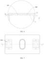
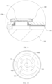
FIG. 10, FIG. 10 is a schematic structural diagram of a secondconcave portion 3 according to some embodiments of this application. In some embodiments of this application, at least part of the thinnedregion 101 is used for welding to theelectrode terminal 123 and forming afirst welding portion 103, and at least part of themain body region 102 is used for welding to theelectrode terminal 123 and forming asecond welding portion 104. The provision of thefirst welding portion 103 and thesecond welding portion 104 allows both themain body region 102 and thinnedregion 101 on the first connectingportion 10 to be welded to theelectrode terminal 123, improving the stability of the connection between the connectingcomponent 140 and theelectrode terminal 123. - The
first welding portion 103 is a weld joint formed after the thinnedregion 101 is welded to theelectrode terminal 123, and thesecond welding portion 104 is a weld joint formed after themain body region 102 is welded to theelectrode terminal 123. - In some embodiments of this application, the
first welding portion 103 and thesecond welding portion 104 are connected as one entity. Thefirst welding portion 103 and thesecond welding portion 104 are connected as one entity, which can improve the overall integrity of the weld part, making the connection between the connectingcomponent 140 and theelectrode terminal 123 more stable. - The
first welding portion 103 and thesecond welding portion 104 being connected as one entity means that after welding, thefirst welding portion 103 and thesecond welding portion 104 have overlapping welding tracks or are integrally formed. - Optionally, after welding, the resulting welding track may be in the form of a ring, a spiral line, or a grid.
- In some embodiments of this application, the first connecting
portion 10 is laser welded to theelectrode terminal 123. The first connectingportion 10 is laser welded to theelectrode terminal 123, which can increase the depth of fusion of the thinnedregion 101 during welding, and improve the strength of the connection between the first connectingportion 10 and theelectrode terminal 123. - As shown in
FIG. 6 , in some embodiments of this application, the connectingcomponent 140 is further provided with a first concave portion 1, where the first concave portion 1 is recessed from a surface of the connectingcomponent 140 away from theelectrode terminal 123, and the thinnedregion 101 corresponds to a bottom surface of the first concave portion 1. Provision of the first concave portion 1 facilitates the formation of the thinnedregion 101 and allows the thinnedregion 101 to be integrally formed with themain body region 102, improving the integrity of the connectingcomponent 140. - Optionally, the first concave portion 1 may be a groove formed by milling on the surface of the first connecting
portion 10 away from theelectrode terminal 123. Optionally, in a plane perpendicular to a thickness direction of the first connectingportion 10, the thinnedregion 101 coincides with the bottom surface coverage of the first concave portion 1. - As shown in
FIG. 5 andFIG. 6 , in some embodiments of this application, the connectingcomponent 140 is further provided with a second connectingportion 20, aconvex portion 2, and a secondconcave portion 3. The second connectingportion 20 is configured to connect theelectrode assembly 130; theconvex portion 2 protrudes from a surface of the connectingcomponent 140 towards theelectrode terminal 123; and a position of the secondconcave portion 3 corresponds to theconvex portion 2 in the thickness direction (the x-axis direction inFIGs. 5 and6 ) of the connectingcomponent 140, and the secondconcave portion 3 is recessed from the surface of the connectingcomponent 140 away from theelectrode terminal 123 and extends into theconvex portion 2. - The provision of the second connecting
portion 20 allows the connectingcomponent 140 to connect theelectrode assembly 130; the provision of theconvex portion 2 enables the connectingcomponent 140 to fit more closely to theelectrode terminal 123, improving the welding stability of the connectingcomponent 140 and theelectrode terminal 123; and the provision of the secondconcave portion 3 makes the convex portion 2 a cavity structure, and reduces the thickness at theconvex portion 2, facilitating the welding of theconvex portion 2 to theelectrode terminal 123. - Optionally, the first connecting
portion 10 and the second connectingportion 20 may be disposed on two sides of the connectingcomponent 140. Optionally, thehousing 120 is further provided with an electrode lead-out hole for theelectrode terminal 123 to be connected from the inside of thehousing 120 to the outside of thehousing 120 to conduct the electrical energy generated on theelectrode assembly 130. For example, theelectrode terminal 123 may further include a fixingblock 125. Part of the fixingblock 125 is provided at the top of the electrode lead-out hole, so that a side of the electrode lead-out hole close to the connectingcomponent 140 is vacant to form an accommodating portion. Another part of the fixingblock 125 is provided at the outside of thehousing 120, theterminal plate 124 is provided within the fixingblock 125, theconvex portion 2 matches the accommodating portion, and theterminal plate 124 and the connectingcomponent 140 are welded to the accommodating portion via theconvex portion 2. - Optionally, the
convex portion 2 may be integrally formed with the connectingcomponent 140, and the secondconcave portion 3 may be obtained by milling the connectingcomponent 140. Optionally, theconvex portion 2 may be formed on the connection by stamping, and the secondconcave portion 3 is a groove formed when theconvex portion 2 is formed by stamping. Optionally, the shape and structure of theconvex portion 2 may be determined based on the shape and structure of the accommodating portion, such as a cylindrical protrusion or a square protrusion. Optionally, the shape and structure of the secondconcave portion 3 may be determined based on the shape and structure of theconvex portion 2, such as a cylindrical groove or a square groove. - As shown in
FIG. 5 , in some embodiments of this application, a bottom surface of the secondconcave portion 3 corresponding to theconvex portion 2 includes a first connectingportion 10. Provision of the first connectingportion 10 on theconvex portion 2 allows the first connectingportion 10 to protrude toward theelectrode terminal 123, so that the first connectingportion 10 fits on the surface of theelectrode terminal 123, improving stability of the welding. - As shown in
FIG. 6 , in some embodiments of this application, thickness of the connectingcomponent 140 is L1 and depth of the first concave portion 1 is L2, satisfying 0 < L2/L1 ≤ 0.8. Limiting the thickness of the first concave portion 1 can ensure an increased depth of fusion within the thinnedregion 101 during welding. If the thickness of the thinnedregion 101 is too small, the welding surface will be too far from the laser emission point, which significantly increases the defocus amount and decreases the welding strength, leading to a reduced depth of fusion. Additionally, limiting the thickness of the first concave portion 1 can also prevent the thinnedregion 101 from being too thin and melt off during welding. - Optionally, the thickness of the connecting
component 140 is L1 and the depth of the first concave portion 1 is L2, satisfying 0.2 ≤ L2/L1 ≤ 0.6. Optionally, the thickness of the connectingcomponent 140 is L1 and the depth of the first concave portion 1 is L2, satisfying L2/L1 = 0.4. Optionally, the thickness of the connectingcomponent 140 is L1 and the depth of the first concave portion 1 is L2, satisfying L2/L1 = 0.5. - As shown in
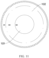
FIG. 11, FIG. 11 is a schematic structural diagram of a secondconcave portion 3 according to some other embodiments of this application. In some embodiments of this application, in a plane perpendicular to the thickness direction, the area of the secondconcave portion 3 is D 1 and the area of the thinnedregion 101 is D2, where 0.2 ≤ D2/D1 ≤ 0.4. The areas of the secondconcave portion 3 and the thinnedregion 101 are limited to ensure an appropriate proportion of the thinnedregion 101 within the secondconcave portion 3, thus improving the strength of the connection. - Optionally, the area of the second
concave portion 3 is D1 and the area of the thinnedregion 101 is D2, where 0.2 ≤ D2/D1 ≤ 0.3. - As shown in
FIG. 11 , in some embodiments of this application, in a plane perpendicular to the thickness direction, the area of the thinnedregion 101 is D2 and the area of the first connectingportion 10 is D3, where 0.3 ≤ D2/D3 ≤ 0.5. The areas of the first connectingportion 10 and the thinnedregion 101 are limited to ensure an appropriate proportion of the thinnedregion 101 within the first connectingportion 10, thus improving the strength of the connection. This can also prevent the thinnedregion 101 from taking up an excessively large proportion, thus avoiding a decrease in the mechanical strength and current-carrying capacity at the first connectingportion 10 of the connectingcomponent 140. - Optionally, the area of the thinned
region 101 is D2 and the area of the first connectingportion 10 is D3, where 0.3 ≤ D2/D3 ≤ 0.4. - As shown in
FIG. 10 andFIG. 11 , in some embodiments of this application, in a plane perpendicular to the thickness direction, the thinnedregion 101 is circular. The thinnedregion 101 is designed as circular so that the junction between the thinnedregion 101 and themain body region 102 is curved, which facilitates the dispersion of the force on the first connectingportion 10 to the thinnedregion 101 and themain body region 102, thus improving the strength of the junction between themain body region 102 and the thinnedregion 101. - In some embodiments of this application, a battery is provided, including the foregoing battery cell.
- In some embodiments of this application, an electric apparatus is provided, including the foregoing battery cell for supplying electrical energy.
- In some embodiments of this application, a battery cell is provided, including a
housing 120, anelectrode terminal 123, anelectrode assembly 130, and a connectingcomponent 140. Theelectrode terminal 123 is provided on thehousing 120, and theelectrode assembly 130 is accommodated in thehousing 120. The connectingcomponent 140 is configured to connect theelectrode terminal 123 and theelectrode assembly 130. The connectingcomponent 140 includes a first connectingportion 10 for connecting theelectrode terminal 123. The first connectingportion 10 includes amain body region 102 and a thinnedregion 101, the thinnedregion 101 having a smaller thickness than themain body region 102, and at least part of the thinnedregion 101 being used for welding to theelectrode terminal 123. At least part of the thinnedregion 101 is used for welding to theelectrode terminal 123 and forming afirst welding portion 103, and at least part of themain body region 102 is used for welding to theelectrode terminal 123 and forming asecond welding portion 104. Thefirst welding portion 103 and thesecond welding portion 104 are connected as one entity, and the first connectingportion 10 is laser welded to theelectrode terminal 123. The connectingcomponent 140 is further provided with a first concave portion 1, where the first concave portion 1 is recessed from a surface of the connectingcomponent 140 away from theelectrode terminal 123, and the thinnedregion 101 corresponds to a bottom surface of the first concave portion 1. The connectingcomponent 140 is further provided with a second connectingportion 20, aconvex portion 2, and a secondconcave portion 3. The second connectingportion 20 is configured to connect theelectrode assembly 130; theconvex portion 2 protrudes from a surface of the connectingcomponent 140 towards theelectrode terminal 123; and a position of the secondconcave portion 3 corresponds to theconvex portion 2 in the thickness direction of the connectingcomponent 140, and the secondconcave portion 3 is recessed from the surface of the connectingcomponent 140 away from theelectrode terminal 123 and extends into theconvex portion 2. The thickness of the connectingcomponent 140 is L1 and the depth of the first concave portion 1 is L2, satisfying 0 < L2/L1 ≤ 0.8. In a plane perpendicular to the thickness direction, the area of the secondconcave portion 3 is D1 and the area of the thinnedregion 101 is D2, where 0.2 ≤ D2/D1 ≤ 0.4. In a plane perpendicular to the thickness direction, the area of the thinnedregion 101 is D2 and the area of the first connectingportion 10 is D3, where 0.3 ≤ D2/D3 ≤ 0.5. - A connecting
component 140 with a thickness of 1 mm was used. The connectingcomponent 140 includes aconvex portion 2 formed by stamping. A circular thinnedregion 101 is formed on the surface of the recessed side on theconvex portion 2. The thinnedregion 101 accounts for 30% of the area of the entire recessed side of the protrusion, and the overlap rate between the thinnedregion 101 and the welding region is 40%. The thinned depth of the thinnedregion 101 is 0.2 mm. The connectingcomponent 140 and theelectrode terminal 123 are laser welded at a welding power of 5.2 KW, where the welding track is in the form of a ring, with an outer diameter of 10 mm and an inner diameter of 9 mm. - This test example is substantially the same as Test Example 1, except that the welding power is 4.2 KW and the thinned depth of the thinned
region 101 is 0.4 mm. - This test example is substantially the same as Test Example 1, except that the welding power is 3.2 KW and the thinned depth of the thinned
region 101 is 0.6 mm. - A connecting
component 140 with a thickness of 1 mm was used. The connectingcomponent 140 includes aconvex portion 2 formed by stamping. The connectingcomponent 140 and theelectrode terminal 123 are laser welded at a welding power of 5.2 KW, where the welding track is in the form of a ring, with an outer diameter of 10 mm and an inner diameter of 9 mm. - This test example is substantially the same as Comparative Example 1, except that the welding power is 4.2 KW.
- This test example is substantially the same as Comparative Example 1, except that the welding power is 3.2 KW.
- Test method: The finished welded workpiece was fixed on the base of the tensile testing machine, with the welding surface facing upwards. The upper gripper was lowered to the specified position, and the connecting component was fixed to the gripper. The tensile testing machine was started to move the upper gripper upwards at a constant speed until the connecting component was separated from the convex portion. The tensile force value was recorded, and data of Test Examples 1 to 3 and Comparative Examples 1 to 3 was collected, as listed in the table below.
Number Tensile force (N) Test Example 1 612 Test Example 2 462 Test Example 3 335 Comparative Example 1 524 Comparative Example 2 328 Comparative Example 3 159 - As can be seen from the above table, under the same welding power, the tolerable tensile force between the connecting
component 140 without the thinnedregion 101 and theelectrode terminal 123 is much lower than that between the connectingcomponent 140 with the thinnedregion 101 and theelectrode terminal 123. The applicant believes that provision of the thinnedregion 101 allows for a greater depth of fusion under the same welding power, resulting in a greater connection strength between the connectingcomponent 140 and theelectrode terminal 123. - Compared with the prior art, in the battery cell, battery, and electric apparatus according to the embodiments of this application, the thinned
region 101 is provided so that the thickness at the thinnedregion 101 is reduced. This allows for a greater depth of fusion at the thinnedregion 101 after the connectingcomponent 140 is welded to theelectrode terminal 123, achieving a more stable connection between the connectingcomponent 140 and theelectrode terminal 123, and preventing the connectingcomponent 140 from separating from theelectrode terminal 123. The greater depth of fusion at the thinnedregion 101 can also reduce the problem of incomplete welds between the connectingcomponent 140 and theelectrode terminal 123, preventing an increase in contact resistance between the connectingcomponent 140 and theelectrode terminal 123 caused by incomplete welds. This in turn improves the consistency of the battery cell during the charging and discharging processes, improves the energy density and cycle life of the battery cell, and enhances the use safety of the battery cell. - Although this application has been described with reference to the preferred embodiments, various modifications can be made to this application without departing from the scope of this application and the components therein can be replaced with equivalents. In particular, as long as there is no structural conflict, the various technical features mentioned in some embodiments can be combined in any manner. This application is not limited to the specific embodiments disclosed in this specification but includes all technical solutions falling within the scope of the claims.
Claims (13)
- A battery cell, comprising:a housing;an electrode terminal provided on the housing;an electrode assembly accommodated in the housing; anda connecting component configured to connect the electrode terminal and the electrode assembly, wherein the connecting component comprises a first connecting portion for connecting the electrode terminal, wherein the first connecting portion comprises a main body region and a thinned region, the thinned region having a smaller thickness than the main body region, and at least part of the thinned region being used for welding to the electrode terminal.
- The battery cell according to claim 1, wherein at least part of the thinned region is used for welding to the electrode terminal and forming a first welding portion, and at least part of the main body region is used for welding to the electrode terminal and forming a second welding portion.
- The battery cell according to claim 2, wherein the first welding portion and the second welding portion are connected as one entity.
- The battery cell according to claim 1 or 2, wherein the first connecting portion is laser welded to the electrode terminal.
- The battery cell according to any one of claims 1 to 4, wherein the connecting component is further provided with a first concave portion, wherein the first concave portion is recessed from a surface of the connecting component away from the electrode terminal, and the thinned region corresponds to a bottom surface of the first concave portion.
- The battery cell according to claim 5, wherein the connecting component is further provided with a second connecting portion, a convex portion, and a second concave portion, whereinthe second connecting portion is configured to connect the electrode assembly;the convex portion protrudes from a surface of the connecting component towards the electrode terminal; anda position of the second concave portion corresponds to the convex portion in a thickness direction of the connecting component, and the second concave portion is recessed from the surface of the connecting component away from the electrode terminal and extends into the convex portion.
- The battery cell according to claim 6, wherein a bottom surface of the second concave portion corresponding to the convex portion comprises the first connecting portion.
- The battery cell according to claim 6 or 7, wherein thickness of the connecting component is L1 and depth of the first concave portion is L2, satisfying 0 < L2/L1 ≤ 0.8.
- The battery cell according to any one of claims 6 to 8, wherein in a plane perpendicular to the thickness direction, the area of the second concave portion is D1 and the area of the thinned region is D2, wherein 0.2 ≤ D2/D1 ≤ 0.4.
- The battery cell according to any one of claims 6 to 9, wherein in a plane perpendicular to the thickness direction, the area of the thinned region is D2 and the area of the first connecting portion is D3, wherein 0.3 ≤ D2/D3 ≤ 0.5.
- The battery cell according to claim 9 or 10, wherein in a plane perpendicular to the thickness direction, the thinned region is circular.
- A battery, comprising the battery cell according to any one of claims 1 to 11.
- An electric apparatus, comprising the battery cell according to any one of claims 1 to 11 for supplying electrical energy.
Applications Claiming Priority (2)
| Application Number | Priority Date | Filing Date | Title |
|---|---|---|---|
| CN202210734115.8A CN114824680B (en) | 2022-06-27 | 2022-06-27 | Battery cell, battery and power consumption device |
| PCT/CN2022/123631 WO2024000906A1 (en) | 2022-06-27 | 2022-09-30 | Battery cell, battery, and electric device |
Publications (2)
| Publication Number | Publication Date |
|---|---|
| EP4395050A1 true EP4395050A1 (en) | 2024-07-03 |
| EP4395050A4 EP4395050A4 (en) | 2025-07-16 |
Family
ID=82522312
Family Applications (1)
| Application Number | Title | Priority Date | Filing Date |
|---|---|---|---|
| EP22948992.7A Pending EP4395050A4 (en) | 2022-06-27 | 2022-09-30 | BATTERY CELL, BATTERY AND ELECTRICAL DEVICE |
Country Status (4)
| Country | Link |
|---|---|
| US (1) | US20240363977A1 (en) |
| EP (1) | EP4395050A4 (en) |
| CN (1) | CN114824680B (en) |
| WO (1) | WO2024000906A1 (en) |
Families Citing this family (10)
| Publication number | Priority date | Publication date | Assignee | Title |
|---|---|---|---|---|
| CN114824680B (en) * | 2022-06-27 | 2022-11-08 | 江苏时代新能源科技有限公司 | Battery cell, battery and power consumption device |
| CN115603003A (en) * | 2022-09-23 | 2023-01-13 | 广州小鹏汽车科技有限公司(Cn) | Current collecting disc and battery |
| CN219350578U (en) * | 2023-03-09 | 2023-07-14 | 欣旺达电动汽车电池有限公司 | single battery |
| CN118645770A (en) * | 2023-03-13 | 2024-09-13 | 宁德时代新能源科技股份有限公司 | Transition component, battery cell, battery and electrical device |
| CN220774656U (en) * | 2023-05-23 | 2024-04-12 | 宁德时代新能源科技股份有限公司 | Connecting member, battery cell, battery, electrical device and connecting piece |
| WO2025010683A1 (en) * | 2023-07-12 | 2025-01-16 | 深圳海辰储能控制技术有限公司 | End cover assembly, energy storage device, and energy storage system |
| CN116581489B (en) * | 2023-07-12 | 2024-04-30 | 深圳海辰储能控制技术有限公司 | End cover assembly, energy storage device and energy storage system |
| CN119581807B (en) * | 2023-09-07 | 2026-03-03 | 宁德时代新能源科技股份有限公司 | Battery cells, batteries and electrical devices |
| CN221708901U (en) * | 2023-09-26 | 2024-09-13 | 宁德时代新能源科技股份有限公司 | Battery monomer, battery and power consumption device |
| WO2025189467A1 (en) * | 2024-03-15 | 2025-09-18 | 宁德时代新能源科技股份有限公司 | Battery cell, battery, and electric device |
Family Cites Families (13)
| Publication number | Priority date | Publication date | Assignee | Title |
|---|---|---|---|---|
| JP4135516B2 (en) * | 2003-01-23 | 2008-08-20 | ソニー株式会社 | Lead terminal and power supply |
| CN106450136B (en) * | 2016-11-15 | 2020-02-14 | 宁德时代新能源科技股份有限公司 | Secondary battery and battery module |
| CN207233789U (en) * | 2017-08-30 | 2018-04-13 | 宁德时代新能源科技股份有限公司 | Secondary cell and battery modules |
| CN207676989U (en) * | 2017-12-27 | 2018-07-31 | 星恒电源股份有限公司 | Electrode connecting structure for power battery |
| CN109103408A (en) * | 2018-07-05 | 2018-12-28 | 湖北锂诺新能源科技有限公司 | Aluminium connection sheet in power battery module |
| CN209056523U (en) * | 2018-11-07 | 2019-07-02 | 宁德时代新能源科技股份有限公司 | Secondary battery |
| JP7296208B2 (en) * | 2018-12-27 | 2023-06-22 | 三洋電機株式会社 | Secondary battery and assembled battery |
| CN209169274U (en) * | 2018-12-28 | 2019-07-26 | 蜂巢能源科技有限公司 | Connecting piece for battery pack and battery pack having the same |
| CN216720236U (en) * | 2022-01-17 | 2022-06-10 | 宁德时代新能源科技股份有限公司 | Adapters, battery cells, batteries and electrical devices |
| CN114388990B (en) * | 2022-02-24 | 2025-10-28 | 中创新航科技集团股份有限公司 | Batteries and battery packs |
| CN216648533U (en) * | 2022-03-21 | 2022-05-31 | 宁德时代新能源科技股份有限公司 | Current collecting member, battery cell, battery, and power consumption device |
| CN217182373U (en) * | 2022-04-08 | 2022-08-12 | 宁德时代新能源科技股份有限公司 | Connecting member, battery cell, battery, and electric device |
| CN114824680B (en) * | 2022-06-27 | 2022-11-08 | 江苏时代新能源科技有限公司 | Battery cell, battery and power consumption device |
-
2022
- 2022-06-27 CN CN202210734115.8A patent/CN114824680B/en active Active
- 2022-09-30 WO PCT/CN2022/123631 patent/WO2024000906A1/en not_active Ceased
- 2022-09-30 EP EP22948992.7A patent/EP4395050A4/en active Pending
-
2024
- 2024-07-09 US US18/767,921 patent/US20240363977A1/en active Pending
Also Published As
| Publication number | Publication date |
|---|---|
| US20240363977A1 (en) | 2024-10-31 |
| CN114824680A (en) | 2022-07-29 |
| WO2024000906A1 (en) | 2024-01-04 |
| CN114824680B (en) | 2022-11-08 |
| EP4395050A4 (en) | 2025-07-16 |
Similar Documents
| Publication | Publication Date | Title |
|---|---|---|
| EP4395050A1 (en) | Battery cell, battery, and electric device | |
| US20240243444A1 (en) | Electrode plate, electrode assembly, battery cell, battery, and electric device | |
| US20240154218A1 (en) | Battery cell, battery, and electrical apparatus | |
| EP4645579A1 (en) | Battery cell, battery, and electric device | |
| WO2025166480A1 (en) | Battery cell, battery, and electrical apparatus | |
| KR20250164880A (en) | Battery, apparatus, battery preparing method, and device | |
| US20250087854A1 (en) | Battery cell, battery, and electric apparatus | |
| EP4664582A1 (en) | Battery cell, battery, and electric device | |
| US20240088532A1 (en) | Welding member, Cylindrical Battery and Electric Apparatus | |
| US20230369728A1 (en) | Electrode assembly, method and system for manufacturing same, battery cell, battery, and electric apparatus | |
| US20260045660A1 (en) | Battery cell, method for manufacturing battery cell, battery, and electrical apparatus | |
| US20240332541A1 (en) | Electrode plate, electrode assembly, battery cell, battery, and electric device | |
| US12166242B2 (en) | Electrode plate, electrode assembly, battery cell, battery, and electric device | |
| US20240339625A1 (en) | Battery electrode plate, electrode assembly, battery cell, battery, and electric device | |
| US12249723B2 (en) | Battery, electric device, and method and device for preparing battery cell | |
| CN119812690B (en) | Battery monomer, preparation method of battery monomer, battery and electricity utilization device | |
| EP4510256A1 (en) | Battery cell, battery, and electrical apparatus | |
| CN222126917U (en) | Battery monomer, battery, power utilization device and energy storage device | |
| CN223230485U (en) | Battery cell, battery device, electricity utilization device and energy storage device | |
| EP4432375A1 (en) | Battery cell, battery and electric device | |
| US20260024888A1 (en) | Adapter sheet, secondary battery, battery assembly and electronic device | |
| CN222507915U (en) | Battery monomer, battery, power utilization device and energy storage device | |
| US20260011752A1 (en) | Battery, Battery Pack and Vehicle Including the Same | |
| US20250087811A1 (en) | Support assembly, battery box, battery, and electric device | |
| US20260112788A1 (en) | Current collector, battery cell including the same, and method of manufacturing the same |
Legal Events
| Date | Code | Title | Description |
|---|---|---|---|
| STAA | Information on the status of an ep patent application or granted ep patent |
Free format text: STATUS: THE INTERNATIONAL PUBLICATION HAS BEEN MADE |
|
| PUAI | Public reference made under article 153(3) epc to a published international application that has entered the european phase |
Free format text: ORIGINAL CODE: 0009012 |
|
| STAA | Information on the status of an ep patent application or granted ep patent |
Free format text: STATUS: REQUEST FOR EXAMINATION WAS MADE |
|
| 17P | Request for examination filed |
Effective date: 20240327 |
|
| AK | Designated contracting states |
Kind code of ref document: A1 Designated state(s): AL AT BE BG CH CY CZ DE DK EE ES FI FR GB GR HR HU IE IS IT LI LT LU LV MC MK MT NL NO PL PT RO RS SE SI SK SM TR |
|
| A4 | Supplementary search report drawn up and despatched |
Effective date: 20250618 |
|
| RIC1 | Information provided on ipc code assigned before grant |
Ipc: H01M 50/533 20210101AFI20250612BHEP Ipc: H01M 50/536 20210101ALI20250612BHEP |
|
| DAV | Request for validation of the european patent (deleted) | ||
| DAX | Request for extension of the european patent (deleted) |