EP4395047A1 - Battery unit, battery module, and vehicle - Google Patents
Battery unit, battery module, and vehicle Download PDFInfo
- Publication number
- EP4395047A1 EP4395047A1 EP22909467.7A EP22909467A EP4395047A1 EP 4395047 A1 EP4395047 A1 EP 4395047A1 EP 22909467 A EP22909467 A EP 22909467A EP 4395047 A1 EP4395047 A1 EP 4395047A1
- Authority
- EP
- European Patent Office
- Prior art keywords
- electrode tab
- electrode
- electrode terminal
- battery unit
- housing
- Prior art date
- Legal status (The legal status is an assumption and is not a legal conclusion. Google has not performed a legal analysis and makes no representation as to the accuracy of the status listed.)
- Pending
Links
Images


Classifications
-
- H—ELECTRICITY
- H01—ELECTRIC ELEMENTS
- H01M—PROCESSES OR MEANS, e.g. BATTERIES, FOR THE DIRECT CONVERSION OF CHEMICAL ENERGY INTO ELECTRICAL ENERGY
- H01M50/00—Constructional details or processes of manufacture of the non-active parts of electrochemical cells other than fuel cells, e.g. hybrid cells
- H01M50/50—Current conducting connections for cells or batteries
- H01M50/571—Methods or arrangements for affording protection against corrosion; Selection of materials therefor
-
- H—ELECTRICITY
- H01—ELECTRIC ELEMENTS
- H01M—PROCESSES OR MEANS, e.g. BATTERIES, FOR THE DIRECT CONVERSION OF CHEMICAL ENERGY INTO ELECTRICAL ENERGY
- H01M50/00—Constructional details or processes of manufacture of the non-active parts of electrochemical cells other than fuel cells, e.g. hybrid cells
- H01M50/10—Primary casings; Jackets or wrappings
- H01M50/102—Primary casings; Jackets or wrappings characterised by their shape or physical structure
- H01M50/103—Primary casings; Jackets or wrappings characterised by their shape or physical structure prismatic or rectangular
-
- H—ELECTRICITY
- H01—ELECTRIC ELEMENTS
- H01M—PROCESSES OR MEANS, e.g. BATTERIES, FOR THE DIRECT CONVERSION OF CHEMICAL ENERGY INTO ELECTRICAL ENERGY
- H01M50/00—Constructional details or processes of manufacture of the non-active parts of electrochemical cells other than fuel cells, e.g. hybrid cells
- H01M50/50—Current conducting connections for cells or batteries
- H01M50/531—Electrode connections inside a battery casing
- H01M50/533—Electrode connections inside a battery casing characterised by the shape of the leads or tabs
-
- H—ELECTRICITY
- H01—ELECTRIC ELEMENTS
- H01M—PROCESSES OR MEANS, e.g. BATTERIES, FOR THE DIRECT CONVERSION OF CHEMICAL ENERGY INTO ELECTRICAL ENERGY
- H01M50/00—Constructional details or processes of manufacture of the non-active parts of electrochemical cells other than fuel cells, e.g. hybrid cells
- H01M50/50—Current conducting connections for cells or batteries
- H01M50/531—Electrode connections inside a battery casing
- H01M50/54—Connection of several leads or tabs of plate-like electrode stacks, e.g. electrode pole straps or bridges
-
- H—ELECTRICITY
- H01—ELECTRIC ELEMENTS
- H01M—PROCESSES OR MEANS, e.g. BATTERIES, FOR THE DIRECT CONVERSION OF CHEMICAL ENERGY INTO ELECTRICAL ENERGY
- H01M50/00—Constructional details or processes of manufacture of the non-active parts of electrochemical cells other than fuel cells, e.g. hybrid cells
- H01M50/50—Current conducting connections for cells or batteries
- H01M50/543—Terminals
- H01M50/552—Terminals characterised by their shape
- H01M50/553—Terminals adapted for prismatic, pouch or rectangular cells
-
- H—ELECTRICITY
- H01—ELECTRIC ELEMENTS
- H01M—PROCESSES OR MEANS, e.g. BATTERIES, FOR THE DIRECT CONVERSION OF CHEMICAL ENERGY INTO ELECTRICAL ENERGY
- H01M2220/00—Batteries for particular applications
- H01M2220/20—Batteries in motive systems, e.g. vehicle, ship, plane
-
- H—ELECTRICITY
- H01—ELECTRIC ELEMENTS
- H01M—PROCESSES OR MEANS, e.g. BATTERIES, FOR THE DIRECT CONVERSION OF CHEMICAL ENERGY INTO ELECTRICAL ENERGY
- H01M50/00—Constructional details or processes of manufacture of the non-active parts of electrochemical cells other than fuel cells, e.g. hybrid cells
- H01M50/20—Mountings; Secondary casings or frames; Racks, modules or packs; Suspension devices; Shock absorbers; Transport or carrying devices; Holders
- H01M50/249—Mountings; Secondary casings or frames; Racks, modules or packs; Suspension devices; Shock absorbers; Transport or carrying devices; Holders specially adapted for aircraft or vehicles, e.g. cars or trains
-
- H—ELECTRICITY
- H01—ELECTRIC ELEMENTS
- H01M—PROCESSES OR MEANS, e.g. BATTERIES, FOR THE DIRECT CONVERSION OF CHEMICAL ENERGY INTO ELECTRICAL ENERGY
- H01M50/00—Constructional details or processes of manufacture of the non-active parts of electrochemical cells other than fuel cells, e.g. hybrid cells
- H01M50/50—Current conducting connections for cells or batteries
- H01M50/572—Means for preventing undesired use or discharge
- H01M50/584—Means for preventing undesired use or discharge for preventing incorrect connections inside or outside the batteries
- H01M50/586—Means for preventing undesired use or discharge for preventing incorrect connections inside or outside the batteries inside the batteries, e.g. incorrect connections of electrodes
-
- Y—GENERAL TAGGING OF NEW TECHNOLOGICAL DEVELOPMENTS; GENERAL TAGGING OF CROSS-SECTIONAL TECHNOLOGIES SPANNING OVER SEVERAL SECTIONS OF THE IPC; TECHNICAL SUBJECTS COVERED BY FORMER USPC CROSS-REFERENCE ART COLLECTIONS [XRACs] AND DIGESTS
- Y02—TECHNOLOGIES OR APPLICATIONS FOR MITIGATION OR ADAPTATION AGAINST CLIMATE CHANGE
- Y02E—REDUCTION OF GREENHOUSE GAS [GHG] EMISSIONS, RELATED TO ENERGY GENERATION, TRANSMISSION OR DISTRIBUTION
- Y02E60/00—Enabling technologies; Technologies with a potential or indirect contribution to GHG emissions mitigation
- Y02E60/10—Energy storage using batteries
-
- Y—GENERAL TAGGING OF NEW TECHNOLOGICAL DEVELOPMENTS; GENERAL TAGGING OF CROSS-SECTIONAL TECHNOLOGIES SPANNING OVER SEVERAL SECTIONS OF THE IPC; TECHNICAL SUBJECTS COVERED BY FORMER USPC CROSS-REFERENCE ART COLLECTIONS [XRACs] AND DIGESTS
- Y02—TECHNOLOGIES OR APPLICATIONS FOR MITIGATION OR ADAPTATION AGAINST CLIMATE CHANGE
- Y02P—CLIMATE CHANGE MITIGATION TECHNOLOGIES IN THE PRODUCTION OR PROCESSING OF GOODS
- Y02P70/00—Climate change mitigation technologies in the production process for final industrial or consumer products
- Y02P70/50—Manufacturing or production processes characterised by the final manufactured product
Definitions
- a battery unit includes: a housing, where a chamber is defined in the housing; an electrode core, where the electrode core is arranged in the chamber, the electrode core includes a first electrode tab and a second electrode tab, one of the first electrode tab and the second electrode tab is a positive electrode tab, the other one of the first electrode tab and the second electrode tab is a negative electrode tab, and the positive electrode tab is physically and electrically connected to the housing; a first electrode terminal, where the first electrode terminal is electrically connected to the first electrode tab; and a second electrode terminal, where the second electrode terminal is electrically connected to the second electrode tab.
- the positive electrode tab is a bent member having an opening groove
- the battery unit further includes: a first insulation side plate.
- the first insulation side plate is arranged in the opening groove, so that at least a part of the positive electrode tab is located between the first insulation side plate and the upper cover.
- Another objective of the present disclosure is to provide a new technical solution of a battery module, which includes the foregoing battery unit.
- a chamber 21 is defined in the housing 20, the electrode core 10 is arranged in the chamber 21, the electrode core 10 includes at least one first electrode tab 11 and at least one second electrode tab 12, one of the first electrode tab 11 and the second electrode tab 12 is a positive electrode tab, the other one of the first electrode tab 11 and the second electrode tab 12 is a negative electrode tab, and the positive electrode tab is physically and electrically connected to the housing 20.
- the first electrode terminal 41 is electrically connected to the first electrode tab 11, and the second electrode terminal 42 is electrically connected to the second electrode tab 12.
- the battery unit 100 mainly includes the housing 20, the electrode core 10, the first electrode terminal 41, and the second electrode terminal 42.
- the chamber 21 is formed in the housing 20, and the chamber 21 has an accommodating function.
- the electrode core 10 is installed in the chamber 21.
- the electrode core 10 includes the first electrode tab 11 and the second electrode tab 12.
- the first electrode tab 11 is a positive electrode tab
- the second electrode tab 12 is a negative electrode tab.
- the first electrode tab 11 is a negative electrode tab
- the second electrode tab 12 is a positive electrode tab.
- the positive electrode tab is physically and electrically connected to the housing 20, in other words, the positive electrode tab is in physical contact with and electrically connected to the housing 20. Enabling the positive electrode tab to be in direct physical contact with the housing 20 avoids a disadvantage that an internal structure of a battery is complex and required space is large due to use of an interconnection member. In addition, when the positive electrode tab is arranged in a direction of a long axis of the electrode core 10, it can still be ensured that the housing 20 is electrified and has a compact structure.
- physically and electrically connecting the positive electrode tab to the housing 20 can make the housing 20 electrified to prevent the housing 20 from being corroded, simplify a structure inside the battery, and also diversify a position at which the positive electrode tab is arranged.
- the positive electrode tab can be conveniently electrically connected to the housing 20 even if the positive electrode tab is arranged along the long axis of the electrode core 10.
- an end of the first electrode tab 11 or the second electrode tab 12 near the housing 20 includes multiple connection pieces 111 spaced apart.
- the first electrode tab 11 is divided into multiple connection pieces 111, two adjacent connection pieces 111 are spaced apart, and an end of each connection piece 111 is directly connected to the first electrode plate.
- the electrode core 10 has the long axis and a short axis
- the first electrode tab 11 is arranged along the long axis or the short axis
- the second electrode tab 12 is arranged along the long axis or the short axis.
- the first electrode tab 11 is arranged along the long axis
- the second electrode tab 12 may be arranged along the long axis or the short axis.
- the first electrode tab 11 is arranged along the short axis
- the second electrode tab 12 may be arranged along the long axis or the short axis. As shown in FIG.
- the electrode core 10 is approximately a rectangle-like member, and has the long axis (that is, a long edge of the rectangle) and the short axis (that is, a short edge of the rectangle).
- the long axis extends in a first direction
- the short axis extends in a second direction.
- the first direction is nearly perpendicular to the second direction.
- the positive electrode tab is arranged along the long axis, and a size of the long axis is greater than a size of the short axis.
- a requirement for reducing impedance of the electrode core 10 in the first direction is greater than a requirement for reducing impedance of the electrode core 10 in the second direction. Therefore, when the first electrode tab 11 is arranged along the long axis, an impedance reduction effect in the first direction can be ensured.
- due to a limited size of the short axis, especially for a blade battery it is convenient to arrange the first electrode tab 11 in the direction of the long axis.
- the multiple connection pieces 111 are connected in series.
- the first electrode tab 11 may be directly or indirectly connected to the housing 20, so that the housing 20 is electrified.
- the multiple connection pieces 111 connected in series help simplify the intermediate structure used to implement an electrical connection between the first electrode tab 11 and the housing 20.
- the first insulation side plate 30 is arranged in the positive electrode tab, so that the first insulation side plate 30 has a supporting function for the positive electrode tab after the positive electrode tab is folded. In other words, using the first insulation side plate 30 can prevent the positive electrode tab from being excessively squeezed by the housing 20, so as to improve safety performance of the battery unit 100.
- a thickness of the upper cover 23 may be kept at 1-2 mm. This thickness can reduce a deformation degree of the upper cover 23 while ensuring welding strength.
- the positive electrode tab conducts electricity to the positive electrode terminal through the upper cover 23 to form a current path.
- the following describes the battery unit 100 according to the present disclosure in detail with reference to a specific embodiment.
Landscapes
- Chemical & Material Sciences (AREA)
- Chemical Kinetics & Catalysis (AREA)
- Electrochemistry (AREA)
- General Chemical & Material Sciences (AREA)
- Connection Of Batteries Or Terminals (AREA)
- Cell Separators (AREA)
- Battery Mounting, Suspending (AREA)
- Sealing Battery Cases Or Jackets (AREA)
- Gas Exhaust Devices For Batteries (AREA)
Abstract
Description
- The present disclosure claims priority to
Chinese Patent Application No. 202123252716.5, filed on December 21, 2021 - The present disclosure relates to the field of battery technologies, and more specifically, to a battery unit, a battery module to which the battery unit is applied, and a vehicle that includes the battery module.
- A battery usually includes an aluminum shell and a battery core installed inside the aluminum shell. The aluminum shell is typically not electrified. As a reaction occurs inside the battery, lithium reacts with the aluminum shell during the reaction, and lithium ions are embedded into the aluminum shell to form an aluminum-lithium alloy, which corrodes the aluminum shell, and affects a service life of the battery.
- According to an objective of the present disclosure, a battery unit is provided, and includes: a housing, where a chamber is defined in the housing; an electrode core, where the electrode core is arranged in the chamber, the electrode core includes a first electrode tab and a second electrode tab, one of the first electrode tab and the second electrode tab is a positive electrode tab, the other one of the first electrode tab and the second electrode tab is a negative electrode tab, and the positive electrode tab is physically and electrically connected to the housing; a first electrode terminal, where the first electrode terminal is electrically connected to the first electrode tab; and a second electrode terminal, where the second electrode terminal is electrically connected to the second electrode tab.
- In an embodiment of the present disclosure, an end of the first electrode tab or the second electrode tab near the housing includes multiple connection pieces spaced apart.
- In an embodiment of the present disclosure, the electrode core has a long axis and a short axis, the first electrode tab is arranged along the long axis or the short axis, and the second electrode tab is arranged along the long axis or the short axis.
- In an embodiment of the present disclosure, the multiple connection pieces are spaced apart in a direction of the long axis.
- In an embodiment of the present disclosure, the multiple connection pieces are connected in series.
- In an embodiment of the present disclosure, the housing includes: a lower piece, where the chamber is defined in the lower piece with an opening; and an upper cover, where the upper cover is arranged in the opening to seal at least a part of the chamber, and the upper cover is welded to the positive electrode tab.
- In an embodiment of the present disclosure, the first electrode terminal is connected to the upper cover to electrically connect to the positive electrode tab.
- In an embodiment of the present disclosure, the positive electrode tab is a bent member having an opening groove, and the battery unit further includes: a first insulation side plate. The first insulation side plate is arranged in the opening groove, so that at least a part of the positive electrode tab is located between the first insulation side plate and the upper cover.
- In an embodiment of the present disclosure, the first insulation side plate is connected to the electrode core through an adhesive layer.
- In an embodiment of the present disclosure, the battery unit further includes: a second insulation side plate. The second insulation side plate is arranged between the housing and the negative electrode tab, so that the housing is insulated from the negative electrode tab.
- In an embodiment of the present disclosure, the second insulation side plate is connected to the electrode core through an adhesive layer.
- In an embodiment of the present disclosure, one of the first electrode terminal and the second electrode terminal is a positive electrode terminal, and the other one of the first electrode terminal and the second electrode terminal is a negative electrode terminal.
- In an embodiment of the present disclosure, the battery unit further includes: an electrode terminal cover plate. The electrode terminal cover plate is arranged in the housing, and the first electrode terminal and the second electrode terminal is arranged on the electrode terminal cover plate.
- In an embodiment of the present disclosure, the battery unit further includes: a bald cover plate. The bald cover plate is located between the electrode terminal cover plate and the housing, and the bald cover plate is separately electrically connected to the positive electrode terminal and the housing, and is insulated from the negative electrode terminal.
- In an embodiment of the present disclosure, the battery unit further includes: an explosion-proof valve cover plate. The explosion-proof valve cover plate is arranged along the short axis, and the explosion-proof valve cover plate and the electrode terminal cover plate are located on two sides of the long axis.
- According to another objective of the present disclosure, a battery module is provided, and includes the battery unit in any one of the foregoing embodiments.
- According to still another objective of the present disclosure, a vehicle is provided, and includes the battery module in any one of the foregoing embodiments.
- Other features and advantages of the present disclosure will become more apparent from the following detailed description of the example embodiments of the present disclosure with reference to the accompanying drawings.
- The accompanying drawings, which are incorporated in the specification and constitute a part of the specification, illustrate the embodiments of the present disclosure, and together with the description thereof, are used to explain the principle of the present disclosure.
-
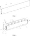
FIG. 1 is a schematic diagram of a structure of a battery according to an embodiment of the present disclosure; -
FIG. 2 is an exploded diagram of a battery according to an embodiment of the present disclosure; -
FIG. 3 is an enlarged view of a region A circled inFIG. 2 ; -
FIG. 4 is a schematic diagram of a partial structure of an electrode core according to an embodiment of the present disclosure; and -
FIG. 5 is a schematic diagram of a connection between a first electrode tab of an electrode core and an upper cover according to an embodiment of the present disclosure. -
-
battery unit 100; -
electrode core 10; -
first electrode tab 11;connection piece 111; openinggroove 112; -
second electrode tab 12; -
housing 20;chamber 21;lower piece 22;upper cover 23; - first
insulation side plate 30; - electrode
terminal cover plate 40; -
first electrode terminal 41;second electrode terminal 42; - explosion-proof
valve cover plate 50; - second
insulation side plate 60; and -
bald cover plate 70. - Various example embodiments of the present disclosure will now be described in detail with reference to the accompanying drawings. It should be noted that the relative arrangements, numeric expressions, and values of the components and steps described in these embodiments are not construed as a limitation on the scope of the present disclosure unless otherwise specified.
- The following descriptions of at least one example embodiment are merely illustrative and are not intended to limit the present disclosure and application or use thereof.
- Techniques, methods, and devices known to a person of ordinary skill in the art may not be discussed in detail, but the techniques, methods, and devices shall be considered as a part of the specification where appropriate.
- In all the examples illustrated and discussed herein, any specific value should be interpreted as merely an example instead of a limitation. Therefore, other examples of example embodiments may have different values.
- It should be noted that similar reference numerals and letters represent similar items in the following accompanying drawings, and therefore, once an item is defined in one of the accompanying drawings, the item does not need to be further discussed in subsequent accompanying drawings.
- An objective of the present disclosure is to provide a new technical solution of a battery unit, to resolve a problem in the related art that a housing of a battery is prone to corrosion.
- Another objective of the present disclosure is to provide a new technical solution of a battery module, which includes the foregoing battery unit.
- Still another objective of the present disclosure is to provide a new technical solution of a vehicle, which includes the foregoing battery module.
- According to embodiments of the present disclosure, physically and electrically connecting a positive electrode tab to a housing can make the housing electrified to prevent the housing from being corroded, simplify a structure inside a battery, and also diversify a position at which the positive electrode tab is arranged. For example, the positive electrode tab can be conveniently electrically connected to the housing even if the positive electrode tab is arranged along a long axis of an electrode core.
- The following describes a
battery unit 100 according to the embodiments of the present disclosure in detail with reference to the accompanying drawings. - As shown in
FIG. 1 to FIG. 5 , thebattery unit 100 according to the embodiments of the present disclosure includes ahousing 20, anelectrode core 10, afirst electrode terminal 41, and asecond electrode terminal 42. - Specifically, a
chamber 21 is defined in thehousing 20, theelectrode core 10 is arranged in thechamber 21, theelectrode core 10 includes at least onefirst electrode tab 11 and at least onesecond electrode tab 12, one of thefirst electrode tab 11 and thesecond electrode tab 12 is a positive electrode tab, the other one of thefirst electrode tab 11 and thesecond electrode tab 12 is a negative electrode tab, and the positive electrode tab is physically and electrically connected to thehousing 20. Thefirst electrode terminal 41 is electrically connected to thefirst electrode tab 11, and thesecond electrode terminal 42 is electrically connected to thesecond electrode tab 12. - In other words, the
battery unit 100 according to the embodiments of the present disclosure mainly includes thehousing 20, theelectrode core 10, thefirst electrode terminal 41, and thesecond electrode terminal 42. Thechamber 21 is formed in thehousing 20, and thechamber 21 has an accommodating function. For example, theelectrode core 10 is installed in thechamber 21. Theelectrode core 10 includes thefirst electrode tab 11 and thesecond electrode tab 12. When thefirst electrode tab 11 is a positive electrode tab, thesecond electrode tab 12 is a negative electrode tab. When thefirst electrode tab 11 is a negative electrode tab, thesecond electrode tab 12 is a positive electrode tab. - The positive electrode tab is physically and electrically connected to the
housing 20, in other words, the positive electrode tab is in physical contact with and electrically connected to thehousing 20. Enabling the positive electrode tab to be in direct physical contact with thehousing 20 avoids a disadvantage that an internal structure of a battery is complex and required space is large due to use of an interconnection member. In addition, when the positive electrode tab is arranged in a direction of a long axis of theelectrode core 10, it can still be ensured that thehousing 20 is electrified and has a compact structure. - Electrically connecting the
housing 20 to the positive electrode tab can enable a voltage of thehousing 20 to be the same as a voltage of a positive electrode, which equivalently means that thehousing 20 is positively electrified, so that the voltage increases. For example, if thehousing 20 is an aluminum shell, a voltage of the aluminum shell increases, and lithium does not react with the high-voltage aluminum shell during a reaction. If the aluminum shell is not electrified or has a negative voltage, lithium ions are embedded into the aluminum shell to form an aluminum-lithium alloy, which corrodes the aluminum shell. - In addition, the
battery unit 100 further includes thefirst electrode terminal 41 and thesecond electrode terminal 42. Thefirst electrode terminal 41 is electrically connected to thefirst electrode tab 11, and thesecond electrode terminal 42 is electrically connected to thesecond electrode tab 12. This can achieve a coupling function. A positive electrode terminal is connected to the positive electrode tab, and a negative electrode terminal is connected to the negative electrode tab. The positive electrode terminal may be electrically connected to the positive electrode tab through thehousing 20. - Therefore, according to the
battery unit 100 in the embodiments of the present disclosure, physically and electrically connecting the positive electrode tab to thehousing 20 can make thehousing 20 electrified to prevent thehousing 20 from being corroded, simplify a structure inside the battery, and also diversify a position at which the positive electrode tab is arranged. For example, the positive electrode tab can be conveniently electrically connected to thehousing 20 even if the positive electrode tab is arranged along the long axis of theelectrode core 10. - According to the embodiments of the present disclosure, an end of the
first electrode tab 11 or thesecond electrode tab 12 near thehousing 20 includesmultiple connection pieces 111 spaced apart. - The
electrode core 10 in the embodiments of the present disclosure may mainly include a first electrode plate, thefirst electrode tab 11, a second electrode plate, thesecond electrode tab 12, and a separator. Thefirst electrode tab 11 is arranged on the first electrode plate, thesecond electrode tab 12 is arranged on the second electrode plate, and the separator is arranged between the first electrode plate and the second electrode plate. - When the end of the
first electrode tab 11 or thesecond electrode tab 12 near thehousing 20 includesmultiple connection pieces 111 spaced apart, the following multiple cases are included. The following uses thefirst electrode tab 11 as an example for description. - A first end of the
first electrode tab 11 is connected to the first electrode plate, a second end of thefirst electrode tab 11 hasmultiple connection pieces 111, and a partition groove exists between twoadjacent connection pieces 111. In other words, the first end of thefirst electrode tab 11 is of an integral structure, and the second end of thefirst electrode tab 11 is of a partition structure. - The
first electrode tab 11 is divided intomultiple connection pieces 111, twoadjacent connection pieces 111 are spaced apart, and an end of eachconnection piece 111 is directly connected to the first electrode plate. - In both case 1 and case 2, compared with a
first electrode tab 11 of an integral structure in the related art, thefirst electrode tab 11 in the present disclosure has a smaller direct current resistance (DCR), so that a DCR of theelectrode core 10 can be reduced. Similarly, thesecond electrode tab 12 usingmultiple connection pieces 111 can also reduce a DCR, and details are not described herein again. In addition, a polarity of thefirst electrode tab 11 is opposite to that of thesecond electrode tab 12. Regardless of whether thefirst electrode tab 11 is a positive electrode tab or a negative electrode tab, an end portion of thefirst electrode tab 11 away from the first electrode plate is divided intomultiple connection pieces 111. - In the embodiments, using
multiple connection pieces 111 can reduce the direct current resistance of thefirst electrode tab 11 or thesecond electrode tab 12, so as to reduce the direct current resistance of theelectrode core 10. - According to the embodiments of the present disclosure, the
electrode core 10 has the long axis and a short axis, thefirst electrode tab 11 is arranged along the long axis or the short axis, and thesecond electrode tab 12 is arranged along the long axis or the short axis. When thefirst electrode tab 11 is arranged along the long axis, thesecond electrode tab 12 may be arranged along the long axis or the short axis. When thefirst electrode tab 11 is arranged along the short axis, thesecond electrode tab 12 may be arranged along the long axis or the short axis. As shown inFIG. 4 , for example, theelectrode core 10 is approximately a rectangle-like member, and has the long axis (that is, a long edge of the rectangle) and the short axis (that is, a short edge of the rectangle). The long axis extends in a first direction, and the short axis extends in a second direction. The first direction is nearly perpendicular to the second direction. - Further, the positive electrode tab is arranged along the long axis, and a size of the long axis is greater than a size of the short axis. A requirement for reducing impedance of the
electrode core 10 in the first direction is greater than a requirement for reducing impedance of theelectrode core 10 in the second direction. Therefore, when thefirst electrode tab 11 is arranged along the long axis, an impedance reduction effect in the first direction can be ensured. In addition, due to a limited size of the short axis, especially for a blade battery, it is convenient to arrange thefirst electrode tab 11 in the direction of the long axis. In other words, designingmultiple connection pieces 111 on a side surface of theelectrode core 10 in a length direction helps reduce a resistance of theentire electrode core 10, especially for a long blade battery. Still further, the negative electrode tab is arranged along the short axis, which facilitates an electrical connection between the negative electrode tab and the negative electrode terminal located on the short axis. In a solution in the related art in which a positive electrode tab and a negative electrode tab are respectively arranged along two short axes opposite to each other, a current of a positive cover plate in the related art flows to an electrodeterminal cover plate 40 through an entire aluminum shell, and in this case, a DCR includes a resistance of the aluminum shell. However, a current of the positive electrode in the present disclosure reaches the positive electrode terminal from a side surface, so that a DCR of the aluminum shell can be reduced. - In some specific implementations of the present disclosure, as shown in
FIG. 4 andFIG. 5 , themultiple connection pieces 111 are spaced apart in the direction of the long axis, which facilitates processing and production. When theelectrode core 10 is applied to thebattery unit 100, themultiple connection pieces 111 are spaced apart in the first direction, so that an intermediate structure for electrically connecting themultiple connection pieces 111 to thehousing 20 can be simplified. - According to the embodiments of the present disclosure, the
multiple connection pieces 111 are connected in series. When theelectrode core 10 is applied to thebattery unit 100, thefirst electrode tab 11 may be directly or indirectly connected to thehousing 20, so that thehousing 20 is electrified. In the embodiments, themultiple connection pieces 111 connected in series help simplify the intermediate structure used to implement an electrical connection between thefirst electrode tab 11 and thehousing 20. - According to the embodiments of the present disclosure, as shown in
FIG. 2 andFIG. 3 , thehousing 20 includes alower piece 22 and anupper cover 23. Thechamber 21 is defined in thelower piece 22 with an opening. Theupper cover 23 is arranged in the opening to seal at least a part of thechamber 21, and theupper cover 23 is welded to the positive electrode tab. - In other words, the
housing 20 may include thelower piece 22 and theupper cover 23, a groove is provided in thelower piece 22, and thelower piece 22 and theupper cover 23 engage with each other to form thechamber 21. As shown inFIG. 5 , the positive electrode tab may first perform ultrasonic pre-welding, the positive electrode tab and theupper cover 23 are welded together by using laser after the ultrasonic pre-welding, and theupper cover 23 is in communication with the positive electrode terminal. A second end of the positive electrode tab may be directly welded to thehousing 20, so that a direct connection between the positive electrode tab and thehousing 20 is implemented, and thehousing 20 is electrified. - According to the embodiments of the present disclosure, the
first electrode terminal 41 is connected to theupper cover 23 to electrically connect to the positive electrode tab. In other words, thefirst electrode terminal 41 is a positive electrode terminal, and the positive electrode terminal is electrically connected to the positive electrode tab through thehousing 20. - According to the embodiments of the present disclosure, as shown in
FIG. 2 andFIG. 3 , the positive electrode tab is a bent member with anopening groove 112, and thebattery unit 100 further includes a firstinsulation side plate 30. The firstinsulation side plate 30 is arranged in theopening groove 112, so that at least a part of the positive electrode tab is located between the firstinsulation side plate 30 and theupper cover 23. In other words, during assembling of thebattery unit 100, the positive electrode tab may be bent. In this case, the positive electrode tab is formed into a "U"-like shape, the "U" shape has anopening groove 112, or the positive electrode tab is formed into a "7"-like shape, and the positive electrode tab engages with another component of theelectrode core 10 to form anopening groove 112. - In the embodiments, the first
insulation side plate 30 is arranged in the positive electrode tab, so that the firstinsulation side plate 30 has a supporting function for the positive electrode tab after the positive electrode tab is folded. In other words, using the firstinsulation side plate 30 can prevent the positive electrode tab from being excessively squeezed by thehousing 20, so as to improve safety performance of thebattery unit 100. - According to the embodiments of the present disclosure, the first
insulation side plate 30 is connected to theelectrode core 10 through an adhesive layer. In other words, the firstinsulation side plate 30 may be fastened to theelectrode core 10 by using a tape, so that theelectrode core 10 can be prevented from moving inside the battery. - In some specific implementations of the present disclosure, as shown in
FIG. 2 andFIG. 3 , thebattery unit 100 further includes a secondinsulation side plate 60, and the secondinsulation side plate 60 is arranged between thehousing 20 and the negative electrode tab, so that thehousing 20 is insulated from the negative electrode tab, and short-circuiting can be avoided. - According to the embodiments of the present disclosure, the second
insulation side plate 60 is connected to theelectrode core 10 through an adhesive layer. In other words, the secondinsulation side plate 60 may be fastened to theelectrode core 10 by using a tape, so that theelectrode core 10 can be prevented from moving inside the battery. - According to the embodiments of the present disclosure, as shown in
FIG. 2 andFIG. 3 , thebattery unit 100 further includes an electrodeterminal cover plate 40, the electrodeterminal cover plate 40 is arranged in thehousing 20, and thefirst electrode terminal 41 and thesecond electrode terminal 42 are arranged on the electrodeterminal cover plate 40. - For example, the electrode
terminal cover plate 40 is arranged along the short axis of theelectrode core 10, and the positive electrode terminal and the negative electrode terminal are arranged on the electrodeterminal cover plate 40. In other words, both the positive electrode terminal and the negative electrode terminal are installed on the electrodeterminal cover plate 40, which facilitates processing and production. In addition, the positive electrode tab is arranged on a side surface, and the positive electrode tab has aconnection piece 111, and therefore, the current of the positive electrode directly reaches the electrodeterminal cover plate 40 from the side surface, so that a DCR of thehousing 20 is reduced. - In some specific implementations of the present disclosure, one of the
first electrode terminal 41 and thesecond electrode terminal 42 is a positive electrode terminal, the other one of thefirst electrode terminal 41 and thesecond electrode terminal 42 is a negative electrode terminal, thebattery unit 100 further includes abald cover plate 70, thebald cover plate 70 is located between the electrodeterminal cover plate 40 and thehousing 20, and thebald cover plate 70 is separately electrically connected to the positive electrode terminal and thehousing 20, and is insulated from the negative electrode terminal. - According to the embodiments of the present disclosure, as shown in
FIG. 2 , thebattery unit 100 further includes an explosion-proofvalve cover plate 50. The explosion-proofvalve cover plate 50 is arranged along the short axis, and the explosion-proofvalve cover plate 50 and the electrodeterminal cover plate 40 are located on two sides of the long axis. Thehousing 20, the electrodeterminal cover plate 40, and the explosion-proofvalve cover plate 50 may be welded to form the sealedchamber 21. - According to the embodiments of the present disclosure, a size of the
electrode core 10 in the direction of the long axis is 700-800 mm, the size of the short axis is approximately 100 mm, and a size of theconnection piece 111 in the direction of the long axis is 30-50 mm. The positive electrode tab is divided intomultiple connection pieces 111. A weld through which eachconnection piece 111 is welded to theupper cover 23 is kept at 26-46 mm. If the weld is excessively large, the weld is easily penetrated. A spacing between twoadjacent connection pieces 111 in the direction of the long axis is kept at 80-100 mm. A quantity ofconnection pieces 111 may be adjusted based on a length of thebattery unit 100. According to the foregoing design, a positive electrode tab can be led out from a side surface of a long blade battery, to optimize a current path and reduce an internal resistance of thebattery unit 100. - In some specific implementations of the present disclosure, a thickness of the
upper cover 23 may be kept at 1-2 mm. This thickness can reduce a deformation degree of theupper cover 23 while ensuring welding strength. The positive electrode tab conducts electricity to the positive electrode terminal through theupper cover 23 to form a current path. - The following describes the
battery unit 100 according to the present disclosure in detail with reference to a specific embodiment. - The
housing 20 includes thelower piece 22 and theupper cover 23. A shape of thehousing 20 is the same as a shape of theelectrode core 10, and theelectrode core 10 is a rectangular member. Theelectrode core 10 has the long axis and the short axis. The long axis extends in a horizontal direction, and the short axis extends in a vertical direction. The positive electrode tab projects from an upper side surface of theelectrode core 10, and the positive electrode tab hasmultiple connection pieces 111, and the negative electrode tab projects from a left side surface of theelectrode core 10. The electrodeterminal cover plate 40 is arranged on a left side surface of thelower piece 22, and the explosion-proofvalve cover plate 50 is arranged on a right side surface of thelower piece 22. The positive electrode terminal and the negative electrode terminal are arranged on the electrodeterminal cover plate 40. Thebald cover plate 70 is arranged between the electrodeterminal cover plate 40 and thehousing 20, and thebald cover plate 70 is insulated from the negative electrode terminal. - After assembling of the battery is completed, the
connection piece 111 is formed into a bent member, and an upper surface of theconnection piece 111 is welded to theupper cover 23. A current path of the battery may be positive electrode terminal->bald cover plate 70->upper cover 23->positive electrode tab->positive electrode plate->negative electrode plate->negative electrode tab->negative electrode terminal. - In conclusion, according to the
battery unit 100 in the embodiments of the present disclosure, thehousing 20 is electrified and allows a current to pass through, so that thebattery unit 100 has an anti-corrosion effect, andmultiple connection pieces 111 are arranged in thefirst electrode tab 11 and/or thesecond electrode tab 12, so that the internal resistance of thebattery unit 100 is reduced. - An embodiment of the present disclosure further provides a battery module. The battery module includes the
battery unit 100 in any one of the foregoing embodiments. Because thebattery unit 100 according to the embodiments of the present disclosure extends a service life of thehousing 20, the battery module according to this embodiment of the present disclosure also has the foregoing advantage. Details are not described herein again. - An embodiment of the present disclosure further provides a vehicle. The vehicle includes the battery module in any one of the foregoing embodiments. Because the battery module according to the embodiments of the present disclosure extends a service life of the
housing 20, the vehicle according to this embodiment of the present disclosure also has the foregoing advantage. Details are not described herein again. - Although some specific embodiments of the present disclosure have been described in detail by using examples, a person skilled in the art should understand that the foregoing examples are merely for description, and are not intended to limit the scope of the present disclosure. A person skilled in the art should understand that the foregoing embodiments may be modified without departing from the scope and spirit of the present disclosure. The scope of the present disclosure is limited by the appended claims.
Claims (17)
- A battery unit (100), comprising:a housing (20), a chamber (21) being defined in the housing (20);an electrode core (10), the electrode core (10) being arranged in the chamber (21), the electrode core (10) comprising a first electrode tab (11) and a second electrode tab (12), one of the first electrode tab (11) and the second electrode tab (12) being a positive electrode tab, the other one of the first electrode tab (11) and the second electrode tab (12) being a negative electrode tab, and the positive electrode tab being physically and electrically connected to the housing (20);a first electrode terminal (41), the first electrode terminal (41) being electrically connected to the first electrode tab (11); anda second electrode terminal (42), the second electrode terminal (42) being electrically connected to the second electrode tab (12).
- The battery unit (100) according to claim 1, wherein an end of the first electrode tab (11) or the second electrode tab (12) near the housing (20) comprises a plurality of connection pieces (111) spaced apart.
- The battery unit (100) according to claim 1 or 2, wherein the electrode core (10) has a long axis and a short axis, the first electrode tab (11) is arranged along the long axis or the short axis, and the second electrode tab (12) is arranged along the long axis or the short axis.
- The battery unit (100) according to any one of claims 1 to 3, wherein the plurality of connection pieces (111) are spaced apart in a direction of the long axis.
- The battery unit (100) according to any one of claims 1 to 4, wherein the plurality of connection pieces (111) are connected in series.
- The battery unit (100) according to any one of claims 1 to 5, wherein the housing (20) comprises:a lower piece (22), wherein the chamber (21) is defined in the lower piece (22) with an opening; andan upper cover (23), wherein the upper cover (23) is arranged in the opening to seal at least a part of the chamber (21), and the upper cover (23) is welded to the positive electrode tab.
- The battery unit (100) according to any one of claims 1 to 6, wherein the first electrode terminal (41) is connected to the upper cover (23) to electrically connect to the positive electrode tab.
- The battery unit (100) according to any one of claims 1 to 7, wherein the positive electrode tab is a bent member having an opening groove (112), and the battery unit (100) further comprising:
a first insulation side plate (30), the first insulation side plate (30) being arranged in the opening groove (112), so that at least a part of the positive electrode tab is located between the first insulation side plate (30) and the upper cover (23). - The battery unit (100) according to any one of claims 1 to 8, wherein the first insulation side plate (30) is connected to the electrode core (10) through an adhesive layer.
- The battery unit (100) according to any one of claims 1 to 9, further comprising:
a second insulation side plate (60), the second insulation side plate (60) being arranged between the housing (20) and the negative electrode tab, so that the housing (20) is insulated from the negative electrode tab. - The battery unit (100) according to any one of claims 1 to 10, wherein the second insulation side plate (60) is connected to the electrode core (10) through an adhesive layer.
- The battery unit (100) according to any one of claims 1 to 11, wherein one of the first electrode terminal (41) and the second electrode terminal (42) is a positive electrode terminal, and the other one of the first electrode terminal (41) and the second electrode terminal (42) is a negative electrode terminal.
- The battery unit (100) according to any one of claims 1 to 12, further comprising:
an electrode terminal cover plate (40), the electrode terminal cover plate (40) being arranged in the housing (20), and the first electrode terminal (41) and the second electrode terminal (42) being arranged on the electrode terminal cover plate (40). - The battery unit (100) according to any one of claims 1 to 13, further comprising:
a bald cover plate (70), the bald cover plate (70) being located between the electrode terminal cover plate (40) and the housing (20), and the bald cover plate (70) being separately electrically connected to the positive electrode terminal and the housing (20), and being insulated from the negative electrode terminal. - The battery unit (100) according to any one of claims 1 to 14, further comprising:
an explosion-proof valve cover plate (50), the explosion-proof valve cover plate (50) being arranged along the short axis, and the explosion-proof valve cover plate (50) and the electrode terminal cover plate (40) being located on two sides of the long axis. - A battery module, comprising the battery unit (100) according to any one of claims 1 to 15.
- A vehicle, comprising the battery module according to claim 16.
Applications Claiming Priority (2)
| Application Number | Priority Date | Filing Date | Title |
|---|---|---|---|
| CN202123252716.5U CN217387458U (en) | 2021-12-21 | 2021-12-21 | Battery cells, battery modules and vehicles |
| PCT/CN2022/125892 WO2023116149A1 (en) | 2021-12-21 | 2022-10-18 | Battery unit, battery module, and vehicle |
Publications (2)
| Publication Number | Publication Date |
|---|---|
| EP4395047A1 true EP4395047A1 (en) | 2024-07-03 |
| EP4395047A4 EP4395047A4 (en) | 2025-07-30 |
Family
ID=83093286
Family Applications (1)
| Application Number | Title | Priority Date | Filing Date |
|---|---|---|---|
| EP22909467.7A Pending EP4395047A4 (en) | 2021-12-21 | 2022-10-18 | BATTERY UNIT, BATTERY MODULE AND VEHICLE |
Country Status (6)
| Country | Link |
|---|---|
| US (1) | US20240266696A1 (en) |
| EP (1) | EP4395047A4 (en) |
| JP (1) | JP2024542350A (en) |
| KR (1) | KR20240063984A (en) |
| CN (1) | CN217387458U (en) |
| WO (1) | WO2023116149A1 (en) |
Families Citing this family (3)
| Publication number | Priority date | Publication date | Assignee | Title |
|---|---|---|---|---|
| CN217387457U (en) * | 2021-12-21 | 2022-09-06 | 比亚迪股份有限公司 | Battery unit, battery module and vehicle |
| CN217387458U (en) * | 2021-12-21 | 2022-09-06 | 比亚迪股份有限公司 | Battery cells, battery modules and vehicles |
| CN114583406A (en) * | 2022-03-31 | 2022-06-03 | 蔚来汽车科技(安徽)有限公司 | Battery core, battery core module, power battery pack and vehicle |
Family Cites Families (8)
| Publication number | Priority date | Publication date | Assignee | Title |
|---|---|---|---|---|
| JP4056279B2 (en) * | 2002-03-29 | 2008-03-05 | 松下電器産業株式会社 | battery |
| KR20200053463A (en) * | 2017-06-15 | 2020-05-18 | 에이일이삼 시스템즈, 엘엘씨 | Stacked prismatic architecture for electrochemical cells |
| CN110061178B (en) * | 2018-01-18 | 2024-10-15 | 比亚迪股份有限公司 | Battery, battery pack and automobile |
| KR102742761B1 (en) * | 2019-01-23 | 2024-12-16 | 주식회사 엘지에너지솔루션 | The Electrode Assembly And The Secondary Battery |
| WO2021244272A1 (en) * | 2020-06-03 | 2021-12-09 | 珠海冠宇电池股份有限公司 | Button-type battery and electronic device |
| CN213546491U (en) * | 2020-11-04 | 2021-06-25 | 上海兰钧新能源科技有限公司 | Secondary batteries and electric vehicles |
| CN217387457U (en) * | 2021-12-21 | 2022-09-06 | 比亚迪股份有限公司 | Battery unit, battery module and vehicle |
| CN217387458U (en) * | 2021-12-21 | 2022-09-06 | 比亚迪股份有限公司 | Battery cells, battery modules and vehicles |
-
2021
- 2021-12-21 CN CN202123252716.5U patent/CN217387458U/en active Active
-
2022
- 2022-10-18 JP JP2024516557A patent/JP2024542350A/en active Pending
- 2022-10-18 EP EP22909467.7A patent/EP4395047A4/en active Pending
- 2022-10-18 KR KR1020247013116A patent/KR20240063984A/en active Pending
- 2022-10-18 WO PCT/CN2022/125892 patent/WO2023116149A1/en not_active Ceased
-
2024
- 2024-04-18 US US18/639,314 patent/US20240266696A1/en active Pending
Also Published As
| Publication number | Publication date |
|---|---|
| CN217387458U (en) | 2022-09-06 |
| EP4395047A4 (en) | 2025-07-30 |
| JP2024542350A (en) | 2024-11-15 |
| US20240266696A1 (en) | 2024-08-08 |
| WO2023116149A1 (en) | 2023-06-29 |
| KR20240063984A (en) | 2024-05-10 |
Similar Documents
| Publication | Publication Date | Title |
|---|---|---|
| EP4395047A1 (en) | Battery unit, battery module, and vehicle | |
| US20210066700A1 (en) | Single-cell battery, battery module, power battery and electric vehicle | |
| CN211605201U (en) | Battery and powered device having the same | |
| US9065083B2 (en) | Lithium polymer battery | |
| US10629882B2 (en) | Battery module | |
| JP6227857B2 (en) | Secondary battery | |
| EP3633766A1 (en) | Electrode member, electrode assembly, and secondary battery | |
| US20240250394A1 (en) | Battery unit, battery module, and vehicle | |
| CN106876621A (en) | Rechargeable battery module | |
| US11929510B2 (en) | Secondary battery and manufacturing method thereof, battery module, and apparatus | |
| CN106450475B (en) | Secondary battery and battery module | |
| US20240243392A1 (en) | Electrochemical apparatus and electronic apparatus | |
| CN114744340A (en) | Single battery and battery pack | |
| CN109244285A (en) | Power battery top cap and power battery | |
| WO2021217649A1 (en) | End cap assembly, secondary battery, battery pack, and powered device | |
| US20210359380A1 (en) | Secondary battery | |
| WO2022067693A1 (en) | Battery module, battery pack, and electronic device | |
| CN116544602A (en) | End cover assembly for battery, single battery, battery pack and electric equipment | |
| EP4310989B1 (en) | Battery module | |
| WO2025214155A1 (en) | Battery and electric device | |
| CN211376668U (en) | Secondary battery, battery module, and device | |
| CN219066998U (en) | Battery end cover | |
| CN115000642A (en) | Square laminated battery | |
| CN218333962U (en) | A heat-dissipating cell and battery | |
| CN224191050U (en) | Battery cover plate and battery |
Legal Events
| Date | Code | Title | Description |
|---|---|---|---|
| STAA | Information on the status of an ep patent application or granted ep patent |
Free format text: STATUS: THE INTERNATIONAL PUBLICATION HAS BEEN MADE |
|
| PUAI | Public reference made under article 153(3) epc to a published international application that has entered the european phase |
Free format text: ORIGINAL CODE: 0009012 |
|
| STAA | Information on the status of an ep patent application or granted ep patent |
Free format text: STATUS: REQUEST FOR EXAMINATION WAS MADE |
|
| 17P | Request for examination filed |
Effective date: 20240327 |
|
| AK | Designated contracting states |
Kind code of ref document: A1 Designated state(s): AL AT BE BG CH CY CZ DE DK EE ES FI FR GB GR HR HU IE IS IT LI LT LU LV MC ME MK MT NL NO PL PT RO RS SE SI SK SM TR |
|
| DAV | Request for validation of the european patent (deleted) | ||
| DAX | Request for extension of the european patent (deleted) | ||
| A4 | Supplementary search report drawn up and despatched |
Effective date: 20250626 |
|
| RIC1 | Information provided on ipc code assigned before grant |
Ipc: H01M 50/531 20210101AFI20250620BHEP Ipc: H01M 50/533 20210101ALI20250620BHEP Ipc: H01M 50/103 20210101ALI20250620BHEP Ipc: H01M 50/571 20210101ALI20250620BHEP Ipc: H01M 50/54 20210101ALI20250620BHEP Ipc: H01M 50/553 20210101ALI20250620BHEP |