EP4395045A1 - Battery core, battery, and electronic device - Google Patents
Battery core, battery, and electronic device Download PDFInfo
- Publication number
- EP4395045A1 EP4395045A1 EP22885713.2A EP22885713A EP4395045A1 EP 4395045 A1 EP4395045 A1 EP 4395045A1 EP 22885713 A EP22885713 A EP 22885713A EP 4395045 A1 EP4395045 A1 EP 4395045A1
- Authority
- EP
- European Patent Office
- Prior art keywords
- battery cell
- insulator
- cell body
- connector
- tab
- Prior art date
- Legal status (The legal status is an assumption and is not a legal conclusion. Google has not performed a legal analysis and makes no representation as to the accuracy of the status listed.)
- Pending
Links
Images




Classifications
-
- H—ELECTRICITY
- H01—ELECTRIC ELEMENTS
- H01M—PROCESSES OR MEANS, e.g. BATTERIES, FOR THE DIRECT CONVERSION OF CHEMICAL ENERGY INTO ELECTRICAL ENERGY
- H01M10/00—Secondary cells; Manufacture thereof
- H01M10/05—Accumulators with non-aqueous electrolyte
- H01M10/052—Li-accumulators
- H01M10/0525—Rocking-chair batteries, i.e. batteries with lithium insertion or intercalation in both electrodes; Lithium-ion batteries
-
- H—ELECTRICITY
- H01—ELECTRIC ELEMENTS
- H01M—PROCESSES OR MEANS, e.g. BATTERIES, FOR THE DIRECT CONVERSION OF CHEMICAL ENERGY INTO ELECTRICAL ENERGY
- H01M50/00—Constructional details or processes of manufacture of the non-active parts of electrochemical cells other than fuel cells, e.g. hybrid cells
- H01M50/50—Current conducting connections for cells or batteries
- H01M50/531—Electrode connections inside a battery casing
-
- H—ELECTRICITY
- H01—ELECTRIC ELEMENTS
- H01M—PROCESSES OR MEANS, e.g. BATTERIES, FOR THE DIRECT CONVERSION OF CHEMICAL ENERGY INTO ELECTRICAL ENERGY
- H01M10/00—Secondary cells; Manufacture thereof
- H01M10/04—Construction or manufacture in general
-
- H—ELECTRICITY
- H01—ELECTRIC ELEMENTS
- H01M—PROCESSES OR MEANS, e.g. BATTERIES, FOR THE DIRECT CONVERSION OF CHEMICAL ENERGY INTO ELECTRICAL ENERGY
- H01M10/00—Secondary cells; Manufacture thereof
- H01M10/05—Accumulators with non-aqueous electrolyte
- H01M10/058—Construction or manufacture
- H01M10/0587—Construction or manufacture of accumulators having only wound construction elements, i.e. wound positive electrodes, wound negative electrodes and wound separators
-
- H—ELECTRICITY
- H01—ELECTRIC ELEMENTS
- H01M—PROCESSES OR MEANS, e.g. BATTERIES, FOR THE DIRECT CONVERSION OF CHEMICAL ENERGY INTO ELECTRICAL ENERGY
- H01M50/00—Constructional details or processes of manufacture of the non-active parts of electrochemical cells other than fuel cells, e.g. hybrid cells
- H01M50/50—Current conducting connections for cells or batteries
- H01M50/502—Interconnectors for connecting terminals of adjacent batteries; Interconnectors for connecting cells outside a battery casing
- H01M50/503—Interconnectors for connecting terminals of adjacent batteries; Interconnectors for connecting cells outside a battery casing characterised by the shape of the interconnectors
-
- H—ELECTRICITY
- H01—ELECTRIC ELEMENTS
- H01M—PROCESSES OR MEANS, e.g. BATTERIES, FOR THE DIRECT CONVERSION OF CHEMICAL ENERGY INTO ELECTRICAL ENERGY
- H01M50/00—Constructional details or processes of manufacture of the non-active parts of electrochemical cells other than fuel cells, e.g. hybrid cells
- H01M50/50—Current conducting connections for cells or batteries
- H01M50/528—Fixed electrical connections, i.e. not intended for disconnection
-
- H—ELECTRICITY
- H01—ELECTRIC ELEMENTS
- H01M—PROCESSES OR MEANS, e.g. BATTERIES, FOR THE DIRECT CONVERSION OF CHEMICAL ENERGY INTO ELECTRICAL ENERGY
- H01M50/00—Constructional details or processes of manufacture of the non-active parts of electrochemical cells other than fuel cells, e.g. hybrid cells
- H01M50/50—Current conducting connections for cells or batteries
- H01M50/531—Electrode connections inside a battery casing
- H01M50/533—Electrode connections inside a battery casing characterised by the shape of the leads or tabs
-
- H—ELECTRICITY
- H01—ELECTRIC ELEMENTS
- H01M—PROCESSES OR MEANS, e.g. BATTERIES, FOR THE DIRECT CONVERSION OF CHEMICAL ENERGY INTO ELECTRICAL ENERGY
- H01M50/00—Constructional details or processes of manufacture of the non-active parts of electrochemical cells other than fuel cells, e.g. hybrid cells
- H01M50/50—Current conducting connections for cells or batteries
- H01M50/531—Electrode connections inside a battery casing
- H01M50/536—Electrode connections inside a battery casing characterised by the method of fixing the leads to the electrodes, e.g. by welding
-
- H—ELECTRICITY
- H01—ELECTRIC ELEMENTS
- H01M—PROCESSES OR MEANS, e.g. BATTERIES, FOR THE DIRECT CONVERSION OF CHEMICAL ENERGY INTO ELECTRICAL ENERGY
- H01M50/00—Constructional details or processes of manufacture of the non-active parts of electrochemical cells other than fuel cells, e.g. hybrid cells
- H01M50/50—Current conducting connections for cells or batteries
- H01M50/531—Electrode connections inside a battery casing
- H01M50/538—Connection of several leads or tabs of wound or folded electrode stacks
-
- H—ELECTRICITY
- H01—ELECTRIC ELEMENTS
- H01M—PROCESSES OR MEANS, e.g. BATTERIES, FOR THE DIRECT CONVERSION OF CHEMICAL ENERGY INTO ELECTRICAL ENERGY
- H01M50/00—Constructional details or processes of manufacture of the non-active parts of electrochemical cells other than fuel cells, e.g. hybrid cells
- H01M50/50—Current conducting connections for cells or batteries
- H01M50/572—Means for preventing undesired use or discharge
- H01M50/584—Means for preventing undesired use or discharge for preventing incorrect connections inside or outside the batteries
- H01M50/586—Means for preventing undesired use or discharge for preventing incorrect connections inside or outside the batteries inside the batteries, e.g. incorrect connections of electrodes
-
- H—ELECTRICITY
- H01—ELECTRIC ELEMENTS
- H01M—PROCESSES OR MEANS, e.g. BATTERIES, FOR THE DIRECT CONVERSION OF CHEMICAL ENERGY INTO ELECTRICAL ENERGY
- H01M50/00—Constructional details or processes of manufacture of the non-active parts of electrochemical cells other than fuel cells, e.g. hybrid cells
- H01M50/50—Current conducting connections for cells or batteries
- H01M50/572—Means for preventing undesired use or discharge
- H01M50/584—Means for preventing undesired use or discharge for preventing incorrect connections inside or outside the batteries
- H01M50/59—Means for preventing undesired use or discharge for preventing incorrect connections inside or outside the batteries characterised by the protection means
- H01M50/593—Spacers; Insulating plates
-
- H—ELECTRICITY
- H01—ELECTRIC ELEMENTS
- H01M—PROCESSES OR MEANS, e.g. BATTERIES, FOR THE DIRECT CONVERSION OF CHEMICAL ENERGY INTO ELECTRICAL ENERGY
- H01M10/00—Secondary cells; Manufacture thereof
- H01M10/04—Construction or manufacture in general
- H01M10/0431—Cells with wound or folded electrodes
-
- Y—GENERAL TAGGING OF NEW TECHNOLOGICAL DEVELOPMENTS; GENERAL TAGGING OF CROSS-SECTIONAL TECHNOLOGIES SPANNING OVER SEVERAL SECTIONS OF THE IPC; TECHNICAL SUBJECTS COVERED BY FORMER USPC CROSS-REFERENCE ART COLLECTIONS [XRACs] AND DIGESTS
- Y02—TECHNOLOGIES OR APPLICATIONS FOR MITIGATION OR ADAPTATION AGAINST CLIMATE CHANGE
- Y02E—REDUCTION OF GREENHOUSE GAS [GHG] EMISSIONS, RELATED TO ENERGY GENERATION, TRANSMISSION OR DISTRIBUTION
- Y02E60/00—Enabling technologies; Technologies with a potential or indirect contribution to GHG emissions mitigation
- Y02E60/10—Energy storage using batteries
-
- Y—GENERAL TAGGING OF NEW TECHNOLOGICAL DEVELOPMENTS; GENERAL TAGGING OF CROSS-SECTIONAL TECHNOLOGIES SPANNING OVER SEVERAL SECTIONS OF THE IPC; TECHNICAL SUBJECTS COVERED BY FORMER USPC CROSS-REFERENCE ART COLLECTIONS [XRACs] AND DIGESTS
- Y02—TECHNOLOGIES OR APPLICATIONS FOR MITIGATION OR ADAPTATION AGAINST CLIMATE CHANGE
- Y02P—CLIMATE CHANGE MITIGATION TECHNOLOGIES IN THE PRODUCTION OR PROCESSING OF GOODS
- Y02P70/00—Climate change mitigation technologies in the production process for final industrial or consumer products
- Y02P70/50—Manufacturing or production processes characterised by the final manufactured product
Definitions
- Embodiments of this application relate to the field of battery technologies, and in particular, to a battery cell, a battery, and an electronic device.
- a wound battery cell is generally terminated on a side of a battery cell body, and a connector is bonded to the tail of an electrode plate on the outermost circle of the battery cell.
- insulators are provided at the joint of a tab and the battery cell body.
- embodiments of this application provide a battery cell, a battery, and an electronic device, so as to improve stability and energy density of the battery.
- a battery cell is provided, where the battery cell includes a battery cell body and at least two tabs provided on the battery cell body, where the battery cell body is formed by winding an electrode assembly formed by stacking a first electrode plate and a second electrode plate, a tail end of the electrode assembly is a free end, and a separator is provided between the first electrode plate and the second electrode plate; and the battery cell further includes a first connector and at least two insulators, where the first connector is provided in a length direction of the battery cell body and is configured to fasten the tail end of the electrode assembly to an outer surface of the battery cell body, the at least two tabs include a first tab and a second tab having opposite polarities, the at least two insulators include a first insulator and a second insulator, a first end of the first insulator is provided on the battery cell body, a second end of the first insulator covers part of the first tab, a first end of the second insul
- the first insulator is provided close to the first connector, and at least part of the first insulator is located outside the first connector.
- Such arrangement allows the first insulator not to be entirely attached to the first connector, avoiding upwarp of the first insulator when the battery cell is top-sealed while such upwarp affects the stability of the battery cell.
- Such arrangement also reduces an overlapping region of the first insulator and the first connector to some extent, thereby increasing the energy density of the battery cell.
- a surface of the first connector in contact with the battery cell body is provided with a binding layer.
- both a front surface and a back surface of the first connector are provided with a binding layer. In this way, bonding force of the insulator can be increased, and the stability of the battery cell can be improved.
- the first insulator in the width direction of the battery cell body, partially overlaps the first connector. In the width direction of the battery cell body, width of the first connector decreases, which prevents the first insulator from being entirely attached to the first connector, thereby increasing the bonding force of the first insulator and improving the stability of the battery cell.
- a gap is present close to between the first insulator and the first connector.
- the first insulator is entirely outside the first connector, fully avoiding the upwarp of the first insulator.
- the first connector in the length direction of the battery cell body, is provided with a notch, and a portion of the first insulator provided on the battery cell body is arranged in the notch. In this way, the bonding force of the insulator is increased, and the stability of the battery cell is improved. In addition, the overlapping region of the first connector and the insulator is reduced, thereby increasing the energy density of the battery cell.
- the battery cell further includes a third tab, where the third tab has a same polarity as the first tab, and the at least two insulators further include a third insulator, where a first end of the third insulator is provided on the battery cell body, a second end of the third insulator covers part of the third tab, and the second tab is provided between the first tab and the third tab in the width direction of the battery cell body.
- the first insulator, the second insulator, and the third insulator are integrally formed. In this way, the bonding force of the insulators is increased, and the stability of the battery cell is improved.
- the outer surface of the battery cell body includes a first plane, a second plane, a first cambered surface, and a second cambered surface, where the first plane and the second plane are provided opposite each other in a thickness direction of the battery cell body, the first cambered surface and the second cambered surface are provided opposite each other in the width direction of the battery cell body, and the first cambered surface and the second cambered surface are connected between the first plane and the second plane.
- the tail end of the electrode assembly is located on the first cambered surface, and the first connector extends from the first plane to the second plane through the first cambered surface.
- the tail end of the electrode assembly is the first electrode plate or the separator, and the first connector covers the entire second electrode plate in the length direction of the battery cell body.
- the first connector and the separator together protect the second electrode plate, preventing burrs of the second electrode plate from impacting the battery cell.
- the tail end of the electrode assembly is located on the first plane, and the first connector extends from the first plane to the second plane through the first cambered surface.
- the tail end of the electrode assembly is the first electrode plate, and a terminating end of the first electrode plate is provided with an uncoated foil zone; or the tail end of the electrode assembly is the separator.
- the first connector in the length direction of the electrode assembly battery cell body, covers part of the first plane, and a gap is present between the first connector and any one of the insulators.
- the first connector is prevented from overlapping the insulator, increasing the bonding force of the insulator and improving the stability and energy density of the battery cell.
- a distance d1 between an edge of the battery cell body and the first insulator is greater than or equal to 0.
- a width d2 of each of the insulators is in a range of 7 mm ⁇ d2 ⁇ 15 mm.
- a width d4 of the first insulator provided outside the first connector satisfies d4>3 mm.
- An embodiment of this application further provides a battery, including the battery cell.
- An embodiment of this application further provides an electronic device, including the battery, where the battery is configured to supply electric energy.
- At least part of the insulator closer to the first connector in the at least two insulators is disposed outside the first connector, preventing the insulator from being entirely attached to the first connector, thereby increasing the bonding force of the insulator and improving the stability and energy density of the battery cell.
- FIG. 1 is a schematic structural diagram of a battery cell 1 according to an embodiment of this application
- FIG. 2 is a schematic planar diagram of the battery cell 1 on a shallow pit surface and a deep pit surface.
- the battery cell 1 includes a battery cell body 100 and at least two tabs provided on the battery cell body.
- the battery cell body is formed by winding an electrode assembly formed by stacking a first electrode plate 10 and a second electrode plate 20, and the first electrode plate 10 and the second electrode plate 20 have opposite polarities.
- a tail end of the electrode assembly is a free end, and a separator 30 is provided between the first electrode plate 10 and the second electrode plate 20.
- the electrode assembly keeps being wound around a winding needle, from a head end to the tail end of the electrode assembly. After the winding is completed, the winding needle is drawn out of the battery cell body.
- the tail end of the electrode assembly refers to a terminating end of the first electrode plate 10, the separator 30, and the second electrode plate 20 that are together wound around the winding needle.
- the terminating end on an outermost circle of the battery cell body is fastened to the outer surface of the battery cell body through the first connector 40.
- the first electrode plate 10 is a cathode plate; the first current collector 11 is optionally an aluminum foil layer; and the first active substance layer 12 is a cathode active substance layer, and optionally an electrochemically active substance capable of deintercalating lithium ions, such as LiCo02 or LiFeP04.
- the second electrode plate 20 is an anode plate; the second current collector 21 is optionally a copper foil layer; and the second active substance layer 22 is optionally an electrochemically active substance capable of intercalating lithium ions, such as graphite, soft carbon, hard carbon, or Li4Ti5012.
- the first plane 101 is a shallow pit surface
- the second plane 102 is a deep pit surface
- the at least two tabs include at least one first tab 60 and at least one second tab 70, where the first tab 60 is connected to the first electrode plate 10, the second tab 70 is connected to the second electrode plate 20, and projections of the first tab 60 and the second tab 70 do not overlap in the thickness direction of the battery cell body.
- first tabs are respectively a first tab 60a and a first tab 60b.
- the at least two insulators include a first insulator 51, a second insulator 52, and a third insulator 53.
- a first insulator 51 an insulator closer to the first connector 40 is the first insulator 51
- a tab closer to the first connector 40 is the first tab 60a.
- an identification code is generally set on the first plane.
- the first insulator 51 is placed outside the first connector 40, so as to prevent the insulator from being entirely attached to the first connector, thereby improving the stability and energy density of the battery cell.
- the first insulator 51 is entirely outside the first connector 40 in the width direction of the battery cell body.
- a gap is present between the first insulator 51 and the first connector 40.
- the first connector 40 is provided with a notch 41 in the length direction of the battery cell body, and a portion of the first insulator 51 provided on the battery cell body is arranged in the notch 41.
- the first insulator 51, the second insulator 52, and the third insulator 53 can be formed individually, as shown in FIG. 7 .
- the first insulator 51, the second insulator 52, and the third insulator 53 may be integrally formed, as shown in FIG. 9 .
- the first connector 40 may be provided with the notch 41, as shown in FIG. 8 .
- the identification code may be set on the first connector or the second connector according to actual situations.
- the outermost circle of the battery cell body is the first electrode plate
- the terminating end 13 of the first electrode plate includes an uncoated foil zone with neither side coated with the first active substance layer 12
- the terminating end 13 of the first electrode plate (the tail end of the electrode assembly) is provided on the first plane 101 or the second plane 102 of the battery cell body, as shown in FIG. 10 .
- the first connector 40 in the length direction of the battery cell body, can cover only part of the first plane or the second plane, provided that a gap is present between the first connector and any one of the insulators in the length direction of the battery cell body. In this way, the first connector can be fully prevented from overlapping the insulator.
- the identification code may be etched on the first connector 40.
- An embodiment of this application further provides a battery, including the battery cell 1.
- An embodiment of this application further provides an electronic device, including the battery.
- the electronic device may be an electric vehicle, a sweeping robot, a mobile phone, a tablet computer, or the like.
- At least part of an insulator closer to the first connector in the at least two insulators are placed outside the first connector. This prevents the insulator from being entirely attached to the first connector, thereby increasing the bonding force of the insulator and improving the stability and energy density of the battery cell.
Landscapes
- Chemical & Material Sciences (AREA)
- Chemical Kinetics & Catalysis (AREA)
- Electrochemistry (AREA)
- General Chemical & Material Sciences (AREA)
- Engineering & Computer Science (AREA)
- Manufacturing & Machinery (AREA)
- Materials Engineering (AREA)
- Connection Of Batteries Or Terminals (AREA)
- Secondary Cells (AREA)
Abstract
Description
- This application claims priority to
Chinese Patent Application No. 202122651483.X, filed with the China National Intellectual Property Administration on November 1, 2021 - Embodiments of this application relate to the field of battery technologies, and in particular, to a battery cell, a battery, and an electronic device.
- A wound battery cell is generally terminated on a side of a battery cell body, and a connector is bonded to the tail of an electrode plate on the outermost circle of the battery cell. In addition, insulators are provided at the joint of a tab and the battery cell body.
- During implementation of this application, inventors of embodiments of this application have found that when the tabs on the terminating side of the battery cell body have a small edge distance, insulating tapes on the tabs may be entirely attached to the connectors, which affects bonding force of the insulators and stability of the battery cell. In addition, since the insulators are entirely attached to the connectors, thickness of the battery cell is increased, which affects energy density of the battery cell.
- To resolve the foregoing technical problem, embodiments of this application provide a battery cell, a battery, and an electronic device, so as to improve stability and energy density of the battery.
- Some embodiments of this application provide the following technical solution for resolving the technical problem: A battery cell is provided, where the battery cell includes a battery cell body and at least two tabs provided on the battery cell body, where the battery cell body is formed by winding an electrode assembly formed by stacking a first electrode plate and a second electrode plate, a tail end of the electrode assembly is a free end, and a separator is provided between the first electrode plate and the second electrode plate; and the battery cell further includes a first connector and at least two insulators, where the first connector is provided in a length direction of the battery cell body and is configured to fasten the tail end of the electrode assembly to an outer surface of the battery cell body, the at least two tabs include a first tab and a second tab having opposite polarities, the at least two insulators include a first insulator and a second insulator, a first end of the first insulator is provided on the battery cell body, a second end of the first insulator covers part of the first tab, a first end of the second insulator is provided on the battery cell body, and a second end of the second insulator covers part of the second tab.
- In a width direction of the battery cell body, the first insulator is provided close to the first connector, and at least part of the first insulator is located outside the first connector.
- Such arrangement allows the first insulator not to be entirely attached to the first connector, avoiding upwarp of the first insulator when the battery cell is top-sealed while such upwarp affects the stability of the battery cell. Such arrangement also reduces an overlapping region of the first insulator and the first connector to some extent, thereby increasing the energy density of the battery cell.
- In some embodiments, a surface of the first connector in contact with the battery cell body is provided with a binding layer.
- In some embodiments, both a front surface and a back surface of the first connector are provided with a binding layer. In this way, bonding force of the insulator can be increased, and the stability of the battery cell can be improved.
- In some embodiments, in the width direction of the battery cell body, the first insulator partially overlaps the first connector. In the width direction of the battery cell body, width of the first connector decreases, which prevents the first insulator from being entirely attached to the first connector, thereby increasing the bonding force of the first insulator and improving the stability of the battery cell.
- In some embodiments, a gap is present close to between the first insulator and the first connector. Thus, the first insulator is entirely outside the first connector, fully avoiding the upwarp of the first insulator.
- In some embodiments, in the length direction of the battery cell body, the first connector is provided with a notch, and a portion of the first insulator provided on the battery cell body is arranged in the notch. In this way, the bonding force of the insulator is increased, and the stability of the battery cell is improved. In addition, the overlapping region of the first connector and the insulator is reduced, thereby increasing the energy density of the battery cell.
- In some embodiments, the battery cell further includes a third tab, where the third tab has a same polarity as the first tab, and the at least two insulators further include a third insulator, where a first end of the third insulator is provided on the battery cell body, a second end of the third insulator covers part of the third tab, and the second tab is provided between the first tab and the third tab in the width direction of the battery cell body.
- In some embodiments, the first insulator, the second insulator, and the third insulator are integrally formed. In this way, the bonding force of the insulators is increased, and the stability of the battery cell is improved.
- In some embodiments, the outer surface of the battery cell body includes a first plane, a second plane, a first cambered surface, and a second cambered surface, where the first plane and the second plane are provided opposite each other in a thickness direction of the battery cell body, the first cambered surface and the second cambered surface are provided opposite each other in the width direction of the battery cell body, and the first cambered surface and the second cambered surface are connected between the first plane and the second plane.
- In some embodiments, the tail end of the electrode assembly is located on the first cambered surface, and the first connector extends from the first plane to the second plane through the first cambered surface.
- In some embodiments, the tail end of the electrode assembly is the first electrode plate or the separator, and the first connector covers the entire second electrode plate in the length direction of the battery cell body. Thus, the first connector and the separator together protect the second electrode plate, preventing burrs of the second electrode plate from impacting the battery cell.
- In some embodiments, the tail end of the electrode assembly is located on the first plane, and the first connector extends from the first plane to the second plane through the first cambered surface.
- In some embodiments, the tail end of the electrode assembly is the first electrode plate, and a terminating end of the first electrode plate is provided with an uncoated foil zone; or the tail end of the electrode assembly is the separator.
- In some embodiments, in the length direction of the electrode assembly battery cell body, the first connector covers part of the first plane, and a gap is present between the first connector and any one of the insulators. Thus, the first connector is prevented from overlapping the insulator, increasing the bonding force of the insulator and improving the stability and energy density of the battery cell.
- In some embodiments, in the width direction of the battery cell body, a distance d1 between an edge of the battery cell body and the first insulator is greater than or equal to 0.
- In some embodiments, in the width direction of the battery cell body, a width d2 of each of the insulators is in a range of 7 mm≤d2≤15 mm.
- In some embodiments, in the width direction of the battery cell body, a width d3 of an overlapping region of the first connector and the first insulator is in a range of 2 mm≤d3≤8 mm.
- In some embodiments, in the width direction of the battery cell body, a width d4 of the first insulator provided outside the first connector satisfies d4>3 mm.
- An embodiment of this application further provides a battery, including the battery cell.
- An embodiment of this application further provides an electronic device, including the battery, where the battery is configured to supply electric energy.
- Beneficial effects of the embodiments of this application are as follows:
- As compared with the prior art, in the battery cell, the battery, and the electronic device provided in the embodiments of this application, at least part of the insulator closer to the first connector in the at least two insulators is disposed outside the first connector, preventing the insulator from being entirely attached to the first connector, thereby increasing the bonding force of the insulator and improving the stability and energy density of the battery cell.
- To describe the technical solutions in the embodiments of this application more clearly, the following briefly describes the accompanying drawings for describing the embodiments of this application. Apparently, the accompanying drawings in the following description show merely some embodiments of this application, and persons of ordinary skill in the art may still derive other drawings from these accompanying drawings without creative efforts.
-
FIG. 1 is a schematic structural diagram of a battery cell according to an embodiment of this application; -
FIG. 2 is a schematic planar diagram of the battery cell in an embodiment of the battery cell shown inFIG. 1 ; -
FIG. 3 is a cross-sectional view of a first tab in a thickness direction of the battery cell body in the battery cell shown inFIG. 1 ; -
FIG. 4 is a schematic planar diagram of a battery cell in the prior art; -
FIG. 5 is a schematic planar diagram of the battery cell in an embodiment of the battery cell shown inFIG. 1 ; -
FIG. 6 is a schematic planar diagram of the battery cell in an embodiment of the battery cell shown inFIG. 1 ; -
FIG. 7 is a schematic planar diagram of the battery cell in an embodiment of the battery cell shown inFIG. 1 ; -
FIG. 8 is a schematic planar diagram of the battery cell in an embodiment of the battery cell shown inFIG. 1 ; -
FIG. 9 is a schematic planar diagram of the battery cell in an embodiment of the battery cell shown inFIG. 1 ; and -
FIG. 10 is a schematic planar diagram of the battery cell in an embodiment of the battery cell shown inFIG. 1 . - For ease of understanding this application, the following further describes this application in detail with reference to the accompanying drawings and specific embodiments. It should be noted that when a component is referred to as being "fixed to" or "connected to" another component, it may be directly fixed to the another component, or there may be one or more components in between. When a component is deemed as being "connected to" another component, it may be directly connected to the another component, or there may be one or more components in between. In the descriptions of this application, the orientations or positional relationships indicated by the terms "end", "lower part", "backward", and the like are based on the orientations or positional relationships shown in the accompanying drawings. Such terms are intended merely for the ease and brevity of description of this application without indicating or implying that the apparatuses or components mentioned in this application must have specified orientations or must be constructed and operated in the specified orientations, and therefore shall not be construed as any limitations on this application. In addition, the terms "first" and "second" are merely intended for a purpose of description, and shall not be understood as an indication or implication of relative importance.
- Unless otherwise defined, all technical and scientific terms used herein shall have the same meanings as commonly understood by those skilled in the art to which this application belongs. The terms used in the specification of this application are merely intended to describe specific embodiments but not to constitute any limitations on this application.
- In addition, technical features involved in different embodiments of this application that are described below may be combined as long as they do not conflict with each other.
- In addition, technical features involved in different embodiments of this application that are described below may be combined as long as they do not conflict with each other.
- Referring to
FIG. 1 and FIG. 2, FIG. 1 is a schematic structural diagram of abattery cell 1 according to an embodiment of this application, andFIG. 2 is a schematic planar diagram of thebattery cell 1 on a shallow pit surface and a deep pit surface. Thebattery cell 1 includes a battery cell body 100 and at least two tabs provided on the battery cell body. The battery cell body is formed by winding an electrode assembly formed by stacking afirst electrode plate 10 and asecond electrode plate 20, and thefirst electrode plate 10 and thesecond electrode plate 20 have opposite polarities. A tail end of the electrode assembly is a free end, and aseparator 30 is provided between thefirst electrode plate 10 and thesecond electrode plate 20. The electrode assembly keeps being wound around a winding needle, from a head end to the tail end of the electrode assembly. After the winding is completed, the winding needle is drawn out of the battery cell body. - Further, the
battery cell 1 further includes afirst connector 40 and at least twoinsulators 50. Thefirst connector 40 is provided in a length direction of the battery cell body and is configured to fasten the tail end of the electrode assembly to an outer surface of the battery cell body. The at least twoinsulators 50 are provided on the battery cell body and cover the at least two tabs, where in the width direction of the battery cell body, at least part of theinsulator 50 closer to thefirst connector 40 in the at least two insulators is located outside thefirst connector 40. - It should be noted that the tail end of the electrode assembly refers to a terminating end of the
first electrode plate 10, theseparator 30, and thesecond electrode plate 20 that are together wound around the winding needle. To be specific, after the winding is completed, the terminating end on an outermost circle of the battery cell body is fastened to the outer surface of the battery cell body through thefirst connector 40. - The
first electrode plate 10 includes a firstcurrent collector 11 and a firstactive substance layer 12, where the firstactive substance layer 12 is provided on a surface of the firstcurrent collector 11. Thesecond electrode plate 20 includes a secondcurrent collector 21 and a secondactive substance layer 22, where the secondactive substance layer 22 is provided on a surface of the secondcurrent collector 21. - In the embodiment of this application, the
first electrode plate 10 is a cathode plate; the firstcurrent collector 11 is optionally an aluminum foil layer; and the firstactive substance layer 12 is a cathode active substance layer, and optionally an electrochemically active substance capable of deintercalating lithium ions, such as LiCo02 or LiFeP04. Thesecond electrode plate 20 is an anode plate; the secondcurrent collector 21 is optionally a copper foil layer; and the secondactive substance layer 22 is optionally an electrochemically active substance capable of intercalating lithium ions, such as graphite, soft carbon, hard carbon, or Li4Ti5012. - It can be understood that the terminating end of the outermost circle of the battery cell body may be the first electrode plate, the second electrode plate, or the separator. For example, in a structure that a terminating
end 13 of thefirst electrode plate 10 is an electrode plate on the outermost circle of the battery cell body, the firstactive substance layer 12 on the terminatingend 13 of thefirst electrode plate 10 covers a side surface of the firstcurrent collector 11 facing thesecond electrode plate 20, and a side surface of the firstcurrent collector 11 on the terminatingend 13 of thefirst electrode plate 10 facing away from thesecond electrode plate 20 is not coated with the firstactive substance layer 12. - In some embodiments, the outer surface of the battery cell body includes a
first plane 101, asecond plane 102, a firstcambered surface 103, and a secondcambered surface 104, where thefirst plane 101 and thesecond plane 102 are provided opposite each other in a thickness direction of the battery cell body, the firstcambered surface 103 and the secondcambered surface 104 are provided opposite each other in the width direction of the battery cell body, and the firstcambered surface 103 and the secondcambered surface 104 are connected between thefirst plane 101 and thesecond plane 102. - In some embodiments, the
first plane 101 is a shallow pit surface, and thesecond plane 102 is a deep pit surface. - The at least two tabs include at least one first tab 60 and at least one
second tab 70, where the first tab 60 is connected to thefirst electrode plate 10, thesecond tab 70 is connected to thesecond electrode plate 20, and projections of the first tab 60 and thesecond tab 70 do not overlap in the thickness direction of the battery cell body. - In the length direction of the battery cell body, the first tab 60 and the
second tab 70 extend out of a same end of the battery cell body. In other embodiments, the first tab 60 and thesecond tab 70 may extend out of different ends of the battery cell body, which is not limited in this application. - In this application, the battery cell including three tabs is used as an example for description. For example, the
battery cell 1 includes two first tabs 60 and onesecond tab 70, and the first tabs 60 and thesecond tab 70 are arranged alternately. For example, the three tabs are arranged in an order of the first tab 60, thesecond tab 70, and the first tab 60 in the width direction of the battery cell body. - For ease of differentiation, the two first tabs are respectively a
first tab 60a and afirst tab 60b. - It can be understood that the
insulators 50 are in one-to-one correspondence with the tabs in quantity, that is, the number of theinsulators 50 is also 3. One end of each of the insulators is provided on the battery cell body, and the other end of each of the insulators covers a corresponding tab. - Specifically, as shown in
FIG. 3 , the at least two insulators include afirst insulator 51, asecond insulator 52, and athird insulator 53. For ease of description, an insulator closer to thefirst connector 40 is thefirst insulator 51, and a tab closer to thefirst connector 40 is thefirst tab 60a. To be specific, a first end of thefirst insulator 51 is provided on the battery cell body, and a second end of thefirst insulator 51 covers part of thefirst tab 60a; a first end of thesecond insulator 52 is provided on the battery cell body, and a second end of thesecond insulator 52 covers part of thesecond tab 70; and a first end of thethird insulator 53 is provided on the battery cell body, and a second end of thethird insulator 53 covers part of thefirst tab 60b. In the width direction of the battery cell body, at least part of thefirst insulator 51 is located outside thefirst connector 40. - In some embodiments, for ease tracing of the
battery cell 1, an identification code is generally set on the first plane. - In the prior art, when the electrode assembly is wound to form the battery cell body, the tail end of the electrode assembly is usually located on a side portion of the battery cell body, and in fastening a tail of the electrode assembly, the first connector needs to extend from the
first plane 101 of the battery cell body to thesecond plane 102 of the battery cell body, as shown inFIG. 4 . However, when a tab (the tab closer to the first connector) has a small edge distance, the insulator on the tab is entirely attached to the first connector, leading to insufficient bonding force of the insulator (the first connector is usually a single-sided adhesive, meaning that a surface of the first connector in contact with the first electrode plate and/or the second electrode plate is provided with a binding layer) and upwarp of the insulator when the battery cell is top-sealed. In addition, the insulator being entirely attached to the first connector leads to more overlapping regions of the insulator and the first connector, affecting the energy density of the battery cell. - In view of this, in this application, at least part of the
first insulator 51 is placed outside thefirst connector 40, so as to prevent the insulator from being entirely attached to the first connector, thereby improving the stability and energy density of the battery cell. - It should be noted that the side portion of the battery cell body refers to a portion of an edge close to the length direction of the battery cell body, when viewed along the thickness direction of the battery cell body, that is, the first
cambered surface 103 or the secondcambered surface 104 on the outer surface of the battery cell body. - It can be understood that the tail end of the electrode assembly may be located on the side portion of the battery cell body, or may be located on the first plane or second plane of the battery cell body.
- It should be noted that when the tail end of the electrode assembly is located on the side portion of the battery cell body, and a terminating end of a single-sided cathode plate (a side of the terminating end of the cathode plate facing the anode plate is coated with a cathode active substance, and a side facing away from the anode plate is coated with no cathode active substance) is located on the outermost circle of the battery cell body, the
first connector 40 covers the entire second electrode plate in the length direction of the battery cell body. In other words, in the length direction of the battery cell body, the first connector needs to be longer than the second electrode plate, so as to avoid damage caused by burrs on the second electrode plate. When the tail end of the electrode assembly is located on the first plane or the second plane of the battery cell body, the first connector is only required to cover part of the first plane or the second plane in the length direction of the battery cell body. - In some embodiments, the tail end of the electrode assembly is located on the side portion of the battery cell body, and the
first insulator 51 partially overlaps thefirst connector 40, as shown inFIG. 2 . Specifically, in the width direction of the battery cell body, a portion of thefirst insulator 51 is provided on thefirst connector 40, and another portion of thefirst insulator 51 is provided on the first plane and/or the second plane. As compared with the prior art, the width of the first connector decreases in the width direction of the battery cell body. If the identification code needs to be set on the first plane, the identification code is attached to the first plane independently. For example, the battery cell further includes asecond connector 80, thesecond connector 80 is provided on the first plane and spaced apart from thefirst connector 40, and the identification code is set on thesecond connector 80. - In this case, in the width direction of the battery cell body, a distance d1 between the first insulator and an edge of the battery cell body is greater than or equal to 0.
- In some embodiments, in the width direction of the battery cell body, a width d2 of the first insulator is in a range of 7 mm≤d2≤15 mm.
- It can be understood that width of the
second insulator 52 and width of thethird insulator 53 also need to satisfy the foregoing condition. - In some embodiments, in the width direction of the battery cell body, a width d3 of the
first tab 60a on the first connector is in a range of 2 mm≤d3≤8 mm. - In some embodiments, in the width direction of the battery cell body, a portion of the
first insulator 51 provided outside thefirst connector 40 has a width d4 satisfying d4≥3 mm, that is, the width d4 of a non-overlapping region of thefirst insulator 51 and thefirst connector 40 satisfies d4≥3 mm. - In some embodiments, in the length direction of the battery cell body, a height of a portion of the insulator provided on the battery cell body is greater than or equal to 3 mm.
- In some embodiments, the at least two
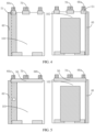
insulators 50 are integrally formed. That is, as shown inFIG. 5 , thefirst insulator 51, thesecond insulator 52, and thethird insulator 53 are integrally formed to increase a binding area of the insulator and the battery cell body. Therefore, there is no need to worry that when thefirst insulator 51 is entirely attached to thefirst connector 40, the first insulator tends to upwarp during top sealing ofbattery cell 1 while such upwarp will cause instability of thebattery cell 1. In this case, the first connector does not need to be narrowed, and the identification code can be etched on thefirst connector 40 without adding thesecond connector 80 separately. - In some embodiments, as shown in
FIG. 6 , in the width direction of the battery cell body, thefirst insulator 51 is entirely outside thefirst connector 40. For example, a gap is present between thefirst insulator 51 and thefirst connector 40. Specifically, thefirst connector 40 is provided with anotch 41 in the length direction of the battery cell body, and a portion of thefirst insulator 51 provided on the battery cell body is arranged in thenotch 41. - It should be noted that, when the tail end of the electrode assembly is provided on the side portion of the battery cell body and the cathode plate is on the outermost circle of the battery cell body, the notch needs to be big enough to allow the
first connector 40 to cover the entire anode plate in the length direction of the battery cell body, so that the first connector and the separator can together protect the anode plate, preventing burrs on the anode plate from damaging the battery cell. - In some embodiments, to ensure the bonding force of the
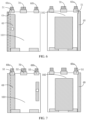
first insulator 51, both the front surface and back surface of thefirst connector 40 are provided with a binding layer, as shown inFIG. 7 . In this case, thefirst insulator 51 can be entirely attached to thefirst connector 40 without causing upwarp of thefirst insulator 51 during top sealing of thebattery cell 1. - It can be understood that, when both the front surface and back surface of the
first connector 41 are provided with a binding layer, thefirst insulator 51, thesecond insulator 52, and thethird insulator 53 can be formed individually, as shown inFIG. 7 . Alternatively, thefirst insulator 51, thesecond insulator 52, and thethird insulator 53 may be integrally formed, as shown inFIG. 9 . Alternatively, thefirst connector 40 may be provided with thenotch 41, as shown inFIG. 8 . The identification code may be set on the first connector or the second connector according to actual situations. - In some embodiments, the outermost circle of the battery cell body is the first electrode plate, the terminating
end 13 of the first electrode plate includes an uncoated foil zone with neither side coated with the firstactive substance layer 12, and the terminatingend 13 of the first electrode plate (the tail end of the electrode assembly) is provided on thefirst plane 101 or thesecond plane 102 of the battery cell body, as shown inFIG. 10 . In this embodiment, in the length direction of the battery cell body, thefirst connector 40 can cover only part of the first plane or the second plane, provided that a gap is present between the first connector and any one of the insulators in the length direction of the battery cell body. In this way, the first connector can be fully prevented from overlapping the insulator. In this case, the identification code may be etched on thefirst connector 40. - It can be understood that the foregoing embodiments are also applicable to a case that the outermost circle of the battery cell body is the
separator 30, and details are not described herein again. - An embodiment of this application further provides a battery, including the
battery cell 1. - An embodiment of this application further provides an electronic device, including the battery.
- The electronic device may be an electric vehicle, a sweeping robot, a mobile phone, a tablet computer, or the like.
- As compared with the prior art, in the battery cell, the battery, and the electronic device provided in the embodiments of this application, at least part of an insulator closer to the first connector in the at least two insulators are placed outside the first connector. This prevents the insulator from being entirely attached to the first connector, thereby increasing the bonding force of the insulator and improving the stability and energy density of the battery cell.
- Finally, it should be noted that the foregoing embodiments are merely intended to describe the technical solutions of this application, and are not intended to limit this application. Under the idea of this application, the foregoing embodiments or the technical features in different embodiments can also be combined, the steps can be implemented in any order, and there are many other changes in different aspects of this application as described above, which, for the sake of brevity, are not provided in detail. Although this application is described in detail with reference to the foregoing embodiments, persons of ordinary skill in the art should understand that modifications can be made to the technical solutions described in the foregoing embodiments, or equivalent substitutions can be made to some technical features therein, and these modifications or substitutions do not make the essence of the corresponding technical solutions depart from the scope of the technical solutions of the embodiments of this application.
Claims (20)
- A battery cell, comprising a battery cell body and at least two tabs provided on the battery cell body, wherein the battery cell body is formed by winding an electrode assembly formed by stacking a first electrode plate and a second electrode plate, a tail end of the electrode assembly is a free end, and a separator is provided between the first electrode plate and the second electrode plate, wherein the battery cell further comprises a first connector and at least two insulators, whereinthe first connector is provided in a length direction of the battery cell body and is configured to fasten the tail end of the electrode assembly to an outer surface of the battery cell body; andthe at least two tabs comprise a first tab and a second tab having opposite polarities, and the at least two insulators comprise a first insulator and a second insulator, wherein a first end of the first insulator is provided on the battery cell body, a second end of the first insulator covers part of the first tab, a first end of the second insulator is provided on the battery cell body, and a second end of the second insulator covers part of the second tab;wherein in a width direction of the battery cell body, the first insulator is provided close to the first connector, and at least part of the first insulator is located outside the first connector.
- The battery cell according to claim 1, wherein
a surface of the first connector in contact with the battery cell body is provided with a binding layer. - The battery cell according to claim 1, wherein
both a front surface and a back surface of the first connector are provided with a binding layer. - The battery cell according to claim 2 or 3, wherein in the width direction of the battery cell body, the first insulator partially overlaps the first connector.
- The battery cell according to claim 2 or 3, wherein
a gap is present between the first insulator and the first connector. - The battery cell according to claim 5, wherein
the first connector is provided with a notch in the length direction of the battery cell body, and a portion of the first insulator provided on the battery cell body is arranged in the notch. - The battery cell according to claim 1, wherein
the battery cell further comprises a third tab, wherein the third tab has a same polarity as the first tab, and the at least two insulators further comprise a third insulator, wherein a first end of the third insulator is provided on the battery cell body, a second end of the third insulator covers part of the third tab, and the second tab is provided between the first tab and the third tab in the width direction of the battery cell body. - The battery cell according to claim 7, wherein
the first insulator, the second insulator, and the third insulator are integrally formed. - The battery cell according to claim 7 or 8, wherein
the outer surface of the battery cell body comprises a first plane, a second plane, a first cambered surface, and a second cambered surface, wherein the first plane and the second plane are provided opposite each other in a thickness direction of the battery cell body, the first cambered surface and the second cambered surface are provided opposite each other in the width direction of the battery cell body, and the first cambered surface and the second cambered surface are connected between the first plane and the second plane. - The battery cell according to claim 9, wherein
the tail end of the electrode assembly is located on the first cambered surface, and the first connector extends from the first plane to the second plane through the first cambered surface. - The battery cell according to claim 9, wherein
the tail end of the electrode assembly is located on the first plane, and the first connector extends from the first plane to the second plane through the first cambered surface. - The battery cell according to claim 10, wherein
the tail end of the electrode assembly is the first electrode plate or the separator, and the first connector covers the entire second electrode plate in the length direction of the battery cell body. - The battery cell according to claim 11, whereinthe tail end of the electrode assembly is the first electrode plate, and a terminating end of the first electrode plate is provided with an uncoated foil zone; orthe tail end of the electrode assembly is the separator.
- The battery cell according to claim 13, wherein
in the length direction of the battery cell body, a gap is present between the first connector and any one of the insulators. - The battery cell according to claim 7 or 8, wherein
in the width direction of the battery cell body, a distance d1 between an edge of the battery cell body and the first insulator is greater than or equal to 0. - The battery cell according to claim 7 or 8, wherein
in the width direction of the battery cell body, a width d2 of each of the insulators is in a range of 7 mm≤d2≤15 mm. - The battery cell according to claim 4, wherein
in the width direction of the battery cell body, a width d3 of an overlapping region of the first connector and the first insulator is in a range of 2 mm≤d3≤8 mm. - The battery cell according to claim 4, wherein
in the width direction of the battery cell body, a width d4 of the first insulator provided outside the first connector satisfies d4≥3 mm. - A battery, comprising the battery cell according to any one of claims 1 to 18.
- An electronic device, comprising the battery according to claim 19, wherein the battery is configured to supply electric energy.
Applications Claiming Priority (2)
| Application Number | Priority Date | Filing Date | Title |
|---|---|---|---|
| CN202122651483.XU CN216213939U (en) | 2021-11-01 | 2021-11-01 | Battery cell, battery and electronic equipment |
| PCT/CN2022/125482 WO2023071835A1 (en) | 2021-11-01 | 2022-10-14 | Battery core, battery, and electronic device |
Publications (2)
| Publication Number | Publication Date |
|---|---|
| EP4395045A1 true EP4395045A1 (en) | 2024-07-03 |
| EP4395045A4 EP4395045A4 (en) | 2025-07-09 |
Family
ID=80898544
Family Applications (1)
| Application Number | Title | Priority Date | Filing Date |
|---|---|---|---|
| EP22885713.2A Pending EP4395045A4 (en) | 2021-11-01 | 2022-10-14 | BATTERY CORE, BATTERY AND ELECTRONIC DEVICE |
Country Status (4)
| Country | Link |
|---|---|
| US (2) | US12592458B2 (en) |
| EP (1) | EP4395045A4 (en) |
| CN (1) | CN216213939U (en) |
| WO (1) | WO2023071835A1 (en) |
Families Citing this family (5)
| Publication number | Priority date | Publication date | Assignee | Title |
|---|---|---|---|---|
| CN216213939U (en) * | 2021-11-01 | 2022-04-05 | 宁德新能源科技有限公司 | Battery cell, battery and electronic equipment |
| WO2024095902A1 (en) * | 2022-10-31 | 2024-05-10 | パナソニックIpマネジメント株式会社 | Power storage device |
| CN116365182A (en) * | 2023-05-31 | 2023-06-30 | 深圳海辰储能控制技术有限公司 | Energy storage device, battery pack and electrical equipment |
| CN116565340B (en) * | 2023-07-10 | 2024-03-12 | 宁德新能源科技有限公司 | Batteries and electrical equipment |
| CN223414126U (en) * | 2024-09-30 | 2025-10-03 | 惠州锂威新能源科技有限公司 | Cells, batteries and electronic devices |
Family Cites Families (18)
| Publication number | Priority date | Publication date | Assignee | Title |
|---|---|---|---|---|
| JP2002343419A (en) | 2001-05-18 | 2002-11-29 | Yuasa Corp | Sealed battery |
| KR100509606B1 (en) * | 2003-02-19 | 2005-08-22 | 삼성에스디아이 주식회사 | Jelly-roll type battery unit and winding method thereof and lithum secondary battery using the same |
| KR101118259B1 (en) | 2009-06-05 | 2012-03-20 | 삼성에스디아이 주식회사 | Electrode assembly and secondary battery using the same |
| KR101165507B1 (en) | 2009-11-27 | 2012-07-13 | 삼성에스디아이 주식회사 | Secondary battery |
| JP6173692B2 (en) * | 2010-12-28 | 2017-08-02 | 三洋電機株式会社 | Nonaqueous electrolyte secondary battery |
| WO2013176161A1 (en) | 2012-05-25 | 2013-11-28 | Necエナジーデバイス株式会社 | Positive electrode for nonaqueous electrolyte battery, and nonaqueous electrolyte battery |
| JP6202347B2 (en) | 2015-06-25 | 2017-09-27 | トヨタ自動車株式会社 | Non-aqueous electrolyte secondary battery |
| CN205543092U (en) * | 2016-01-29 | 2016-08-31 | 中山市众旺德新能源科技有限公司 | Lithium ion battery |
| CN113169290A (en) | 2018-12-27 | 2021-07-23 | 三洋电机株式会社 | Electrode plate and secondary battery using the same |
| CN111403789B (en) | 2019-01-02 | 2021-12-10 | 东莞新能源科技有限公司 | Electrode assembly and battery |
| CN110034268B (en) * | 2019-03-13 | 2021-10-08 | 中山普纳斯能源科技有限公司 | A kind of winding arc battery and its making method |
| CN210092210U (en) * | 2019-05-28 | 2020-02-18 | 东莞新能源科技有限公司 | Battery |
| CN115275365B (en) * | 2019-09-25 | 2025-08-19 | 荣耀终端股份有限公司 | Battery module supporting high-power quick charge, charging module and electronic equipment |
| CN112889181B (en) | 2020-01-20 | 2022-06-17 | 宁德新能源科技有限公司 | Electrode assembly and battery |
| EP3940855A4 (en) | 2020-05-20 | 2022-04-20 | Ningde Amperex Technology Ltd. | Electrode assembly and battery |
| CN213278324U (en) * | 2020-08-31 | 2021-05-25 | 浙江锂威能源科技有限公司 | A wound battery |
| CN113437443B (en) * | 2021-06-21 | 2023-06-20 | 东莞新能安科技有限公司 | Electrochemical devices and electronic devices |
| CN216213939U (en) * | 2021-11-01 | 2022-04-05 | 宁德新能源科技有限公司 | Battery cell, battery and electronic equipment |
-
2021
- 2021-11-01 CN CN202122651483.XU patent/CN216213939U/en active Active
-
2022
- 2022-10-14 WO PCT/CN2022/125482 patent/WO2023071835A1/en not_active Ceased
- 2022-10-14 EP EP22885713.2A patent/EP4395045A4/en active Pending
-
2024
- 2024-05-01 US US18/651,842 patent/US12592458B2/en active Active
- 2024-10-11 US US18/912,866 patent/US12548861B2/en active Active
Also Published As
| Publication number | Publication date |
|---|---|
| WO2023071835A1 (en) | 2023-05-04 |
| US12548861B2 (en) | 2026-02-10 |
| CN216213939U (en) | 2022-04-05 |
| US20250038367A1 (en) | 2025-01-30 |
| EP4395045A4 (en) | 2025-07-09 |
| US12592458B2 (en) | 2026-03-31 |
| US20240283101A1 (en) | 2024-08-22 |
Similar Documents
| Publication | Publication Date | Title |
|---|---|---|
| US12548861B2 (en) | Battery cell with overlap between insulator and connector, battery, and electronic device | |
| US12183931B2 (en) | Current collecting member, secondary battery, and method for manufacturing secondary battery | |
| EP4583182A1 (en) | Pole piece, electrochemical device, and electronic device | |
| US11271274B2 (en) | Secondary battery | |
| EP2958177B1 (en) | Electrode assembly having rounded corners | |
| US10651498B2 (en) | Secondary battery and vehicle | |
| US11380964B2 (en) | Wound electrode assembly | |
| US20240006585A1 (en) | Electrode plate and preparation method thereof, battery, and electronic apparatus | |
| US11245135B2 (en) | Secondary battery with insulating tapes | |
| US12315960B2 (en) | Current collecting member and manufacturing method thereof, secondary battery and manufacturing method thereof, battery module, and apparatus | |
| CN113557625B (en) | Battery cell, battery and electronic device | |
| US20240405255A1 (en) | Battery cell, battery, and electrical device | |
| EP3716387A1 (en) | Battery cell and battery using the same | |
| US20240030521A1 (en) | Battery and electric device | |
| CN218004916U (en) | Pole piece, cell structure and battery and electronic equipment with same | |
| EP4394967A2 (en) | Electrochemical apparatus and electronic device | |
| CN114976512A (en) | Pole piece, electric core structure, lithium battery and electronic equipment | |
| EP3678252A1 (en) | Winding battery | |
| WO2022196937A1 (en) | Cylindrical secondary battery | |
| US20250118864A1 (en) | Electrochemical device and electric device | |
| US20250023116A1 (en) | Electrochemical device and electric device | |
| US20260031511A1 (en) | Electrode assembly and electrochemical device | |
| US20240030433A1 (en) | Electrode assembly, battery, and electrical device | |
| US20240079737A1 (en) | Electrode assembly, electrochemical apparatus, and electric device | |
| US20260128383A1 (en) | Cell and electric device |
Legal Events
| Date | Code | Title | Description |
|---|---|---|---|
| STAA | Information on the status of an ep patent application or granted ep patent |
Free format text: STATUS: THE INTERNATIONAL PUBLICATION HAS BEEN MADE |
|
| PUAI | Public reference made under article 153(3) epc to a published international application that has entered the european phase |
Free format text: ORIGINAL CODE: 0009012 |
|
| STAA | Information on the status of an ep patent application or granted ep patent |
Free format text: STATUS: REQUEST FOR EXAMINATION WAS MADE |
|
| 17P | Request for examination filed |
Effective date: 20240329 |
|
| AK | Designated contracting states |
Kind code of ref document: A1 Designated state(s): AL AT BE BG CH CY CZ DE DK EE ES FI FR GB GR HR HU IE IS IT LI LT LU LV MC ME MK MT NL NO PL PT RO RS SE SI SK SM TR |
|
| DAV | Request for validation of the european patent (deleted) | ||
| DAX | Request for extension of the european patent (deleted) | ||
| A4 | Supplementary search report drawn up and despatched |
Effective date: 20250611 |
|
| RIC1 | Information provided on ipc code assigned before grant |
Ipc: H01M 50/503 20210101ALI20250604BHEP Ipc: H01M 50/528 20210101AFI20250604BHEP |
|
| STAA | Information on the status of an ep patent application or granted ep patent |
Free format text: STATUS: EXAMINATION IS IN PROGRESS |
|
| 17Q | First examination report despatched |
Effective date: 20260327 |