EP4395043A2 - Busbar assembly, battery module, and battery pack - Google Patents
Busbar assembly, battery module, and battery pack Download PDFInfo
- Publication number
- EP4395043A2 EP4395043A2 EP23217790.7A EP23217790A EP4395043A2 EP 4395043 A2 EP4395043 A2 EP 4395043A2 EP 23217790 A EP23217790 A EP 23217790A EP 4395043 A2 EP4395043 A2 EP 4395043A2
- Authority
- EP
- European Patent Office
- Prior art keywords
- support
- busbar
- cells
- busbars
- cell
- Prior art date
- Legal status (The legal status is an assumption and is not a legal conclusion. Google has not performed a legal analysis and makes no representation as to the accuracy of the status listed.)
- Granted
Links
Images

Classifications
-
- H—ELECTRICITY
- H01—ELECTRIC ELEMENTS
- H01M—PROCESSES OR MEANS, e.g. BATTERIES, FOR THE DIRECT CONVERSION OF CHEMICAL ENERGY INTO ELECTRICAL ENERGY
- H01M50/00—Constructional details or processes of manufacture of the non-active parts of electrochemical cells other than fuel cells, e.g. hybrid cells
- H01M50/50—Current conducting connections for cells or batteries
- H01M50/502—Interconnectors for connecting terminals of adjacent batteries; Interconnectors for connecting cells outside a battery casing
- H01M50/503—Interconnectors for connecting terminals of adjacent batteries; Interconnectors for connecting cells outside a battery casing characterised by the shape of the interconnectors
-
- H—ELECTRICITY
- H01—ELECTRIC ELEMENTS
- H01M—PROCESSES OR MEANS, e.g. BATTERIES, FOR THE DIRECT CONVERSION OF CHEMICAL ENERGY INTO ELECTRICAL ENERGY
- H01M50/00—Constructional details or processes of manufacture of the non-active parts of electrochemical cells other than fuel cells, e.g. hybrid cells
- H01M50/50—Current conducting connections for cells or batteries
- H01M50/502—Interconnectors for connecting terminals of adjacent batteries; Interconnectors for connecting cells outside a battery casing
- H01M50/507—Interconnectors for connecting terminals of adjacent batteries; Interconnectors for connecting cells outside a battery casing comprising an arrangement of two or more busbars within a container structure, e.g. busbar modules
-
- Y—GENERAL TAGGING OF NEW TECHNOLOGICAL DEVELOPMENTS; GENERAL TAGGING OF CROSS-SECTIONAL TECHNOLOGIES SPANNING OVER SEVERAL SECTIONS OF THE IPC; TECHNICAL SUBJECTS COVERED BY FORMER USPC CROSS-REFERENCE ART COLLECTIONS [XRACs] AND DIGESTS
- Y02—TECHNOLOGIES OR APPLICATIONS FOR MITIGATION OR ADAPTATION AGAINST CLIMATE CHANGE
- Y02E—REDUCTION OF GREENHOUSE GAS [GHG] EMISSIONS, RELATED TO ENERGY GENERATION, TRANSMISSION OR DISTRIBUTION
- Y02E60/00—Enabling technologies; Technologies with a potential or indirect contribution to GHG emissions mitigation
- Y02E60/10—Energy storage using batteries
Definitions
- a module design of the busbar assembly in embodiments of this application is optimized, and the hole bodies are reserved on the plastic support. Because the hole bodies respectively corresponding to the glue dispensing protrusions that are at the liquid injection holes of the plurality of cells are provided on the support of the busbar assembly, when the busbars are welded to the terminals of the cells, poor welding between the busbars and the terminals of the cells caused because the glue dispensing protrusions lift the support can be avoided. This ensures quality and safety of a battery film group formed by performing, on the cells, sealing performed through steel ball hitting and glue dispensing.
- the hole body is a circle or polygon; and/or two hole bodies corresponding to each cell are provided on the support, where a first end of the cell faces one side of the support, a second end of the cell faces the other side of the support, and one of the two hole bodies corresponds to the glue dispensing protrusion; or the first end of the cell faces the other side of the support, the second end of the cell faces the side of the support, and the other one of the two hole bodies corresponds to the glue dispensing protrusion.
- a shape of the hole body may be selected based on a requirement.
- the two hole bodies corresponding to each cell are provided on the support. No matter whether the first end of the cell corresponds to a first side of the support or the second end of the cell corresponds to the first side of the support, it can be ensured that the glue dispensing protrusion of the cell corresponds to the hole body.
- this application provides a battery module.
- the battery module includes a plurality of cells disposed in parallel, where each cell includes a shell, a steel ball, and a glue dispensing protrusion, a positive terminal, a negative terminal, and a liquid injection hole are provided on the shell, the steel ball is disposed at the liquid injection hole, and the glue dispensing protrusion seals a gap between the steel ball and the liquid injection hole; and the busbar assembly provided in the first aspect, covering the plurality of cells disposed in parallel, where each of a plurality of busbars of the busbar assembly is connected to at least one of the corresponding positive terminal and/or negative terminal.
- this application provides a battery pack.
- the battery pack includes at least one battery module provided in the second aspect.
Landscapes
- Chemical & Material Sciences (AREA)
- Chemical Kinetics & Catalysis (AREA)
- Electrochemistry (AREA)
- General Chemical & Material Sciences (AREA)
- Connection Of Batteries Or Terminals (AREA)
- Battery Mounting, Suspending (AREA)
Abstract
Description
- This application relates to the field of battery technologies, and in particular, to a busbar assembly, a battery module, and a battery pack.
- As a core component of a new energy storage system, a square hard-shell lithium-ion battery is more used. A battery module generally includes a plurality of cells and a busbar assembly. When the busbar assembly is welded to terminals of the plurality of cells, the terminals of the cells and the busbar assembly are prone to be poorly welded; consequently, a product quality problem is caused.
- This application provides a busbar assembly, a battery module, and a battery pack. Hole bodies respectively corresponding to glue dispensing protrusions that are at liquid injection holes of a plurality of cells are provided on a support of the busbar assembly. In this way, when busbars are welded to terminals of the cells, poor welding between the busbars and the terminals of the cells caused because the glue dispensing protrusions lift the support can be avoided, thereby improving product quality and use safety performance.
- According to a first aspect, this application provides a busbar assembly. The busbar assembly includes: a support, where a plurality of hollow-out structures are disposed on the support, and each hollow-out structure is configured to correspond to a terminal of at least one cell of a battery module; and a plurality of busbars, respectively mounted at the plurality of hollow-out structures, where each busbar is configured to connect to the terminal of the at least one cell; and a plurality of hole bodies are further provided on the support, and at least a part of the plurality of hole bodies are configured to respectively correspond to glue dispensing protrusions that are at liquid injection holes of a plurality of cells of the battery module.
- When sealing performed through steel ball hitting and glue dispensing is performed on a liquid injection hole of a square hard-shell cell, glue solidifies, a hard protrusion is formed, and a protrusion height cannot be controlled. In addition, it is inconvenient to check all cells. Because glue dispensing hard protrusions are distributed on the top of the cells, when the busbar assembly covers the cells, and the busbars are welded to terminals of the cells, the hard protrusions are prone to lift the plastic support of the busbar assembly, resulting in poor welding between the terminals of the cells and the busbar assembly and causing a serious product quality problem. For the problem of poor welding of the busbars caused because the plastic support is lifted by the glue dispensing protrusions, a module design of the busbar assembly in embodiments of this application is optimized, and the hole bodies are reserved on the plastic support. Because the hole bodies respectively corresponding to the glue dispensing protrusions that are at the liquid injection holes of the plurality of cells are provided on the support of the busbar assembly, when the busbars are welded to the terminals of the cells, poor welding between the busbars and the terminals of the cells caused because the glue dispensing protrusions lift the support can be avoided. This ensures quality and safety of a battery film group formed by performing, on the cells, sealing performed through steel ball hitting and glue dispensing.
- In a possible implementation, the hole body is a circle or polygon; and/or two hole bodies corresponding to each cell are provided on the support, where a first end of the cell faces one side of the support, a second end of the cell faces the other side of the support, and one of the two hole bodies corresponds to the glue dispensing protrusion; or the first end of the cell faces the other side of the support, the second end of the cell faces the side of the support, and the other one of the two hole bodies corresponds to the glue dispensing protrusion. In this way, a shape of the hole body may be selected based on a requirement. In addition, the two hole bodies corresponding to each cell are provided on the support. No matter whether the first end of the cell corresponds to a first side of the support or the second end of the cell corresponds to the first side of the support, it can be ensured that the glue dispensing protrusion of the cell corresponds to the hole body.
- In a possible implementation, the hollow-out structure includes an opening and a support platform, the busbar is supported and placed at the opening on the support platform, and the support platform includes: at least one boss, disposed in a circumferential direction of the opening; and/or a support rod, where two ends of the support rod are respectively connected to two opposite sides of the opening. In this way, a weight of the support can be reduced, and it is convenient for the busbar to be connected to the terminal of the cell when the busbar is mounted in the hollow-out structure.
- In a possible implementation, the support includes a plurality of first recess portions, the hollow-out structure is disposed at the first recess portion, at least one first limiting clip is disposed at the first recess portion, a gap is provided between the first limiting clip and the support platform in a direction perpendicular to a plane on which the support is located, the busbar is disposed at the gap, and the first limiting clip is configured to clamp and fasten the busbar. In this way, the hollow-out structure is disposed in a recess manner, so that the busbar is reliably connected to the terminal of the cell, and the first limiting clip may fasten a position of the busbar, so that the busbar is mounted more reliably and stably.
- In a possible implementation, the plurality of busbars include: a plurality of first busbars, where each first busbar is configured to connect terminals, of different polarities, of two cells that are adjacent in a first direction, so that the two cells that are adjacent in the first direction are connected in series; and two second busbars, where one of the two second busbars is configured to connect positive terminals of the plurality of cells connected in series, and the other is configured to connect negative terminals of the plurality of cells connected in series. In this way, the plurality of cells may be arranged along the first direction, and adjacent cells are connected in series through the first busbar.
- In a possible implementation, the plurality of busbars further include: a third busbar, configured to connect terminals, of different polarities, of two cells that are adjacent in a second direction, so that the two cells that are adjacent in the second direction are connected in series, where the first direction is perpendicular to the second direction. In this way, a plurality of columns of cells may be disposed along the second direction. Each column of cells may include a plurality of cells arranged along the first direction, each column of cells may be connected in series through the first busbars, and then adjacent columns of cells are connected in series through the third busbar.
- In a possible implementation, at least one via is provided on the busbar, and the busbar is welded to a positive terminal or a negative terminal of the cell at the at least one via. The via is provided, so that the busbar is welded to the terminal of the cell at the via.
- In a possible implementation, the support further includes: a plurality of second recess portions, where the plurality of hole bodies are provided at the plurality of second recess portions, and at least one hole body is provided at each second recess portion; and/or a plurality of third recess portions, where each third recess portion is configured to mount a cable, a second limiting clip is disposed on at least a part of the third recess portion, and the second limiting clip is used to clamp and fasten the cable. In this way, the hole body is provided at the second recess portion, which can better ensure that the hole body corresponds to the glue dispensing protrusion, and can further reduce the weight of the support. In addition, the third recess portion may be disposed on the support to mount the cable, and the second limiting clip may be disposed at the third recess portion to clamp and fasten the cable.
- According to a second aspect, this application provides a battery module. The battery module includes a plurality of cells disposed in parallel, where each cell includes a shell, a steel ball, and a glue dispensing protrusion, a positive terminal, a negative terminal, and a liquid injection hole are provided on the shell, the steel ball is disposed at the liquid injection hole, and the glue dispensing protrusion seals a gap between the steel ball and the liquid injection hole; and the busbar assembly provided in the first aspect, covering the plurality of cells disposed in parallel, where each of a plurality of busbars of the busbar assembly is connected to at least one of the corresponding positive terminal and/or negative terminal.
- According to a third aspect, this application provides a battery pack. The battery pack includes at least one battery module provided in the second aspect.
- Other features and advantages of this application are described in detail in the following specific embodiments.
- The following briefly describes the accompanying drawings that need to be used in the descriptions of embodiments or a conventional technology.
-
FIG. 1 is a schematic diagram of a structure of a busbar assembly according to an embodiment of this application; -
FIG. 2 is an example of a schematic diagram of a structure of a support of the busbar assembly shown inFIG. 1 ; and -
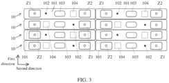
FIG. 3 is an example of a schematic diagram of a partial structure of a battery module according to an embodiment of this application. - The following describes technical solutions in embodiments of this application with reference to accompanying drawings in embodiments of this application.
- In descriptions of this application, locations or location relationships indicated by terms "center", "up", "down", "front", "behind", "left", "right", "vertical", "horizontal", "top", "bottom", "inside", "outside", and the like are based on locations or location relationships shown in the accompanying drawings, and are merely intended for ease of describing this application and simplifying descriptions, instead of indicating or implying that a mentioned apparatus or component needs to be provided on a specific location or constructed and operated on a specific location, and therefore shall not be understood as limitations on this application.
- In the descriptions of this application, it should be noted that, unless otherwise clearly specified and limited, terms "mount", "link", and "connect" should be understood in a broad sense, for example, may mean a fastened connection, may be a detachable connection, or may be a butt joint connection or an integrated connection. Persons of ordinary skill in the art can understand specific meanings of the foregoing terms in this application based on specific cases.
- In the descriptions of this specification, specific features, structures, materials, or characteristics may be combined in a proper manner in any one or more of embodiments.
- When a battery module is produced, liquid injection holes of cells need to be sealed first, and then a busbar assembly covers a plurality of cells, to facilitate welding between the busbar assembly and terminals of the cells. A sealing manner of a liquid injection hole of a square hard-shell lithium-ion battery is to use an automatic device to hit a spherical stainless steel ball into the liquid injection hole on the top of a cell, thereby achieving an effect of sealing the liquid injection hole. Considering that liquid leakage occurs on the top of the cell when the liquid injection hole is sealed by manually hitting the steel ball, a glue dispensing sealing technique may be added to an automatic steel ball hitting technique, to enhance safety and reliability of the cell. However, when the glue dispensing sealing technique is used, a hard protrusion is formed after glue solidifies. When the busbar assembly is welded to terminals of the plurality of cells, there is a risk that the busbar assembly is lifted by glue dispensing hard protrusions, and poor welding of busbars is prone to be caused; consequently, product quality is seriously affected.
- In view of this, embodiments of this application provide a busbar assembly, a battery module, and a battery pack. Hole bodies respectively corresponding to glue dispensing protrusions that are at liquid injection holes of a plurality of cells are provided on a support of the busbar assembly. In this way, when busbars are welded to terminals of the cells, poor welding between the busbars and the terminals of the cells caused because the glue dispensing protrusions lift the support can be avoided, thereby improving product quality and use safety performance. The battery pack may be used in a base station power backup scenario.
-
FIG. 1 is a schematic diagram of a structure of a busbar assembly according to an embodiment of this application.FIG. 2 is an example of a schematic diagram of a structure of a support of the busbar assembly shown inFIG. 1 . As shown inFIG. 1 and FIG. 2 , the busbar assembly includes a support 1 and a plurality ofbusbars 2. A plurality of hollow-outstructures 11 are disposed on the support 1, and each hollow-outstructure 11 is configured to correspond to a terminal of at least one cell of a battery module. The plurality ofbusbars 2 are respectively mounted at the plurality of hollow-outstructures 11, and each busbar is configured to connect to the terminal of the at least one cell. In addition, a plurality ofhole bodies 12 are further provided on the support 1, and at least a part of the plurality ofhole bodies 12 are configured to respectively correspond to glue dispensing protrusions that are at liquid injection holes of a plurality of cells of the battery module. The support may be made of a plastic material. - In the busbar assembly in embodiments of this application, for a problem of poor welding of the busbars caused because the plastic support is lifted by the glue dispensing protrusions, a module design is optimized, and the hole bodies are reserved on the plastic support. Because the hole bodies respectively corresponding to the glue dispensing protrusions that are at the liquid injection holes of the plurality of cells are provided on the support of the busbar assembly, when the busbars are welded to terminals of the cells, poor welding between the busbars and the terminals of the cells caused because the glue dispensing protrusions lift the support can be avoided. This ensures quality and safety of a battery film group formed by performing, on the cells, sealing performed through steel ball hitting and glue dispensing.
- Still refer to
FIG. 1 and FIG. 2 . Thehole body 12 may be a circle. In another example, thehole body 12 may be a polygon. In addition, twohole bodies 12 corresponding to each cell are provided on the support 1. A first end of the cell faces one side of the support 1, a second end of the cell faces the other side of the support 1, and one of the twohole bodies 12 corresponds to the glue dispensing protrusion; or the first end of the cell faces the other side of the support 1, the second end of the cell faces the side of the support 1, and the other one of the twohole bodies 12 corresponds to the glue dispensing protrusion. That is, in order to connect adjacent cells in series, a positive terminal of one of two adjacent cells may be disposed in parallel with a negative terminal of the other one of the two adjacent cells (as shown inFIG. 3 below, a positive terminal Z1 and a negative terminal Z2 ofadjacent cells 10 are disposed in parallel). In this case, positions of glue dispensing protrusions (for example,glue dispensing protrusions 102 inFIG. 3 ) at liquid injection holes of the two adjacent cells are different. To ensure that glue dispensing protrusions all correspond to holebodies 12 and facilitate processing and manufacturing, the twohole bodies 12 corresponding to each cell are provided on the support 1. - As shown in
FIG. 2 , the hollow-outstructure 11 may include anopening 111 and asupport platform 112, the busbar is supported and placed at theopening 111 on thesupport platform 112, and thesupport platform 112 may include at least one boss T1 and/or a support rod T2. The at least one boss T1 is disposed in a circumferential direction of theopening 111. Two ends of the support rod T2 are respectively connected to two opposite sides of theopening 111. InFIG. 2 , theopening 111 is a rectangle, bosses T1 are respectively disposed on two opposite sides of the rectangle, and the two ends of the support rod T2 are respectively connected to the other two opposite sides of the rectangle. In another example, theopening 111 may alternatively be in another shape. - In addition, the support 1 may include a plurality of first recess portions A1, the hollow-out
structure 11 is disposed at the first recess portion A1, at least one first limiting clip K1 is disposed at the first recess portion A1, a gap is provided between the first limiting clip K1 and thesupport platform 112 in a direction perpendicular to a plane on which the support 1 is located, thebusbar 2 is disposed at the gap, and the first limiting clip K1 is configured to clamp and fasten thebusbar 2. That is, the hollow-outstructure 11 is disposed in a recess manner, which facilitates welding between thebusbar 2 and the terminal of the cell, and facilitates arrangement of the first limiting clip K1 to fasten and clamp thebusbar 2. - In some examples, the first limiting clip K1 may be made of an elastic material, the support 1 may be made of an elastic material, and the support 1 and the first limiting clip K1 may be integrated or split.
- In addition, to facilitate welding between the
busbar 2 and the terminal of the cell, at least one via G may be provided on thebusbar 2, and thebusbar 2 is welded to a positive terminal or a negative terminal of the cell at the at least one via G. - As shown in
FIG. 1 , the plurality ofbusbars 2 may include a plurality offirst busbars 2a and twosecond busbars 2b. Eachfirst busbar 2a is configured to connect terminals, of different polarities, of two cells that are adjacent in a first direction, so that the two cells that are adjacent in the first direction are connected in series. One of the twosecond busbars 2b is configured to connect positive terminals of the plurality of cells connected in series, and the other is configured to connect negative terminals of the plurality of cells connected in series. - For example, two vias G may be provided on the
first busbar 2a, one of the two vias G is configured to be welded to a positive terminal of one of the two cells that are adjacent in the first direction, and the other one of the two vias G is configured to be welded to a negative terminal of the other one of the two cells that are adjacent in the first direction. In this way, the two cells that are adjacent in the first direction may be connected in series through thefirst busbar 2a. One via G may be provided on thesecond busbar 2b, one of the twosecond busbars 2b is welded, at the via G, to the positive terminals of the plurality of cells connected in series, and the other one of the twosecond busbars 2b is welded, at the via G, to the negative terminals of the plurality of cells connected in series. - In some examples, as shown in
FIG. 1 , the plurality ofbusbars 2 may further include athird busbar 2c. Thethird busbar 2c is configured to connect terminals, of different polarities, of two cells that are adjacent in a second direction, so that the two cells that are adjacent in the second direction are connected in series, where the first direction is perpendicular to the second direction. For example, two vias G may be provided on thethird busbar 2c, one of the two vias G is configured to be welded to a positive terminal of one of the two cells that are adjacent in the second direction, and the other one of the two vias G is configured to be welded to a negative terminal of the other one of the two cells that are adjacent in the second direction. In this way, the two cells that are adjacent in the second direction may be connected in series through thethird busbar 2c. - In addition, in some examples, the support 1 may further include a plurality of second recess portions A2. The plurality of
hole bodies 12 are respectively provided on the plurality of second recess portions A2, and at least onehole body 12 is provided at each second recess portion A2. Because thehole body 12 is provided at the second recess portion A2, and structural strength is relatively low, the support 1 further includes a reinforcing rib L, and the reinforcing rib L is disposed at the second recess portion A2, so as to improve the structural strength. - In some other examples, the support 1 may further include a plurality of third recess portions A3. Each third recess portion A3 is configured to mount a cable, a second limiting clip K2 is disposed on at least a part of the third recess portion A3, and the second limiting clip K2 is used to clamp and fasten the cable. In addition, the second limiting clip K2 may be made of an elastic material, the support 1 may be made of an elastic material, and the support 1 and the second limiting clip K2 may be integrated or split.
-
FIG. 3 is an example of a schematic diagram of a partial structure of a battery module according to an embodiment of this application. The battery module includes a plurality ofcells 10 disposed in parallel and the foregoing busbar assembly. InFIG. 3 , the busbar assembly of the battery module is removed, that is, only the plurality ofcells 10 are shown. As shown inFIG. 3 , two columns of cells are disposed along a second direction, and each column of cells includes fourcells 10 disposed along a first direction. The busbar assembly covers the plurality ofcells 10 disposed in parallel, and each of a plurality ofbusbars 2 of the busbar assembly is connected to at least one of a corresponding positive terminal Z1 and/or negative terminal Z2. - Each
cell 10 may include ashell 101, a steel ball, and aglue dispensing protrusion 102. The positive terminal Z1, the negative terminal Z2, and a liquid injection hole are provided on theshell 101. The steel ball is disposed at the liquid injection hole. Theglue dispensing protrusion 102 seals a gap between the steel ball and the liquid injection hole. - In addition, an explosion-
proof valve 103 and/or a two-dimensional code 104 may be further disposed on theshell 101. The explosion-proof valve 103 is configured to release pressure in theshell 101 when the pressure in theshell 101 is greater than a pressure threshold. The two-dimensional code 104 is used to store identity information of thecell 10, and two-dimensional codes 104 ondifferent cells 10 store different identity information, that is, the two-dimensional code 104 may be used to identify the identity information of thecell 10. - In addition, embodiments of this application further provide a battery pack. The battery pack includes at least one battery module mentioned above. In addition, when the battery pack includes at least two battery modules mentioned above, the at least two battery modules may be connected in series.
- In conclusion, for a problem of poor welding of the busbars caused because the plastic support is lifted by the glue dispensing protrusions, embodiments of this application provide a module design solution for performing, on cells, sealing performed through steel ball hitting and glue dispensing, which may be applied to all glue dispensing sealed cell group designs, so as to completely avoid a risk of poor welding of busbars of a battery module caused by glue dispensing hard protrusions of liquid injection holes of a lithium-ion battery. Specifically, when the battery module is formed by performing, on the cells, sealing performed through steel ball hitting and glue dispensing, hole bodies such as circular holes are designed in advance at a position corresponding to the glue dispensing protrusions of the plastic support, so as to reserve sufficient space for the glue dispensing protrusions, so that the glue dispensing protrusions are prevented from lifting the support, thereby avoiding a problem of poor welding of the busbars, and ensuring quality and safety of a design of performing, on a cell group, sealing performed through steel ball hitting and glue dispensing.
- It should be noted that the foregoing embodiments are merely intended for describing the technical solutions of this application, but not for limiting this application. Although this application is described in detail with reference to the foregoing embodiments, persons of ordinary skill in the art should understand that they may still make modifications to the technical solutions described in the foregoing embodiments or make equivalent replacements to some technical features thereof, without departing from the scope of the technical solutions of embodiments of this application.
Claims (15)
- A busbar assembly, comprising:a support (1), wherein a plurality of hollow-out structures (11) are disposed on the support (1), and each hollow-out structure (11) is configured to correspond to a terminal of at least one cell of a battery module; anda plurality of busbars (2), respectively mounted at the plurality of hollow-out structures (11), wherein each busbar is configured to connect to the terminal of the at least one cell; anda plurality of hole bodies (12) are further provided on the support (1), and at least a part of the plurality of hole bodies (12) are configured to respectively correspond to a glue dispensing protrusion that is at a liquid injection hole of the at least one cell of the battery module.
- The busbar assembly according to claim 1, whereinthe hole body (12) is a circle or polygon; and/ortwo hole bodies (12) corresponding to each cell are provided on the support (1), wherein a first end of the cell faces one side of the support (1), a second end of the cell faces the other side of the support (1), and one of the two hole bodies (12) corresponds to the glue dispensing protrusion; or the first end of the cell faces the other side of the support (1), the second end of the cell faces the side of the support (1), and the other one of the two hole bodies (12) corresponds to the glue dispensing protrusion.
- The busbar assembly according to claim 1 or 2, wherein the hollow-out structure (11) comprises an opening (111) and a support platform (112), the busbar is supported and placed at the opening (111) on the support platform (112), and the support platform (112) comprises:at least one boss (T1), disposed in a circumferential direction of the opening (111); and/ora support rod (T2), wherein two ends of the support rod (T2) are respectively connected to two opposite sides of the opening (111).
- The busbar assembly according to claim 3, wherein the support (1) comprises a plurality of first recess portions (A1), the hollow-out structure (11) is disposed at the first recess portion (A1), at least one first limiting clip (K1) is disposed at the first recess portion (A 1), a gap is provided between the first limiting clip (K1) and the support platform (112) in a direction perpendicular to a plane on which the support (1) is located, the busbar (2) is disposed at the gap, and the first limiting clip (K1) is configured to clamp and fasten the busbar (2).
- The busbar assembly according to any one of claims 1 to 4, wherein the plurality of busbars (2) comprise:a plurality of first busbars (2a), wherein each first busbar (2a) is configured to connect terminals, of different polarities, of two cells that are adjacent in a first direction, so that the two cells that are adjacent in the first direction are connected in series; andtwo second busbars (2b), wherein one of the two second busbars (2b) is configured to connect positive terminals of the plurality of cells connected in series, and the other is configured to connect negative terminals of the plurality of cells connected in series.
- The busbar assembly according to claim 5, wherein the plurality of busbars (2) further comprise:
a third busbar (2c), configured to connect terminals, of different polarities, of two cells that are adjacent in a second direction, so that the two cells that are adjacent in the second direction are connected in series, wherein the first direction is perpendicular to the second direction. - The busbar assembly according to claim 1 to 6, wherein at least one via (G) is provided on the busbar (2), and the busbar (2) is welded to a positive terminal or a negative terminal of the cell at the at least one via (G).
- The busbar assembly according to any one of claims 1 to 7, wherein the support (1) further comprises:a plurality of second recess portions (A2), wherein the plurality of hole bodies (12) are provided at the plurality of second recess portions (A2), and at least one hole body (12) is provided at each second recess portion (A2); and/ora plurality of third recess portions (A3), wherein each third recess portion (A3) is configured to mount a cable, a second limiting clip (K2) is disposed on at least a part of the third recess portion (A3), and the second limiting clip (K2) is used to clamp and fasten the cable.
- A battery module, comprising:a plurality of cells (10) disposed in parallel, wherein each cell (10) comprises a shell (101), a steel ball, and a glue dispensing protrusion (102), a positive terminal (Z1), a negative terminal (Z2), and a liquid injection hole are provided on the shell (101), the steel ball is disposed at the liquid injection hole, and the glue dispensing protrusion (102) seals a gap between the steel ball and the liquid injection hole; andthe busbar assembly according to any one of claims 1 to 8, covering the plurality of cells (10) disposed in parallel, wherein each of a plurality of busbars (2) of the busbar assembly is connected to at least one of the corresponding positive terminal (Z1) and/or negative terminal (Z2).
- The battery module according to claim 9, whereinthe hole body (12) is a circle or polygon; and/ortwo hole bodies (12) corresponding to each cell are provided on the support (1), wherein a first end of the cell faces one side of the support (1), a second end of the cell faces the other side of the support (1), and one of the two hole bodies (12) corresponds to the glue dispensing protrusion; or the first end of the cell faces the other side of the support (1), the second end of the cell faces the side of the support (1), and the other one of the two hole bodies (12) corresponds to the glue dispensing protrusion.
- The battery module according to claim 9 or 10, wherein the hollow-out structure (11) comprises an opening (111) and a support platform (112), the busbar is supported and placed at the opening (111) on the support platform (112), and the support platform (112) comprises:at least one boss (T1), disposed in a circumferential direction of the opening (111); and/ora support rod (T2), wherein two ends of the support rod (T2) are respectively connected to two opposite sides of the opening (111).
- The battery module according to claim 11, wherein the support (1) comprises a plurality of first recess portions (A1), the hollow-out structure (11) is disposed at the first recess portion (A1), at least one first limiting clip (K1) is disposed at the first recess portion (A1), a gap is provided between the first limiting clip (K1) and the support platform (112) in a direction perpendicular to a plane on which the support (1) is located, the busbar (2) is disposed at the gap, and the first limiting clip (K1) is configured to clamp and fasten the busbar (2).
- The battery module according to any one of claims 9 to 12, wherein the plurality of busbars (2) comprise:a plurality of first busbars (2a), wherein each first busbar (2a) is configured to connect terminals, of different polarities, of two cells that are adjacent in a first direction, so that the two cells that are adjacent in the first direction are connected in series; andtwo second busbars (2b), wherein one of the two second busbars (2b) is configured to connect positive terminals of the plurality of cells connected in series , and the other is configured to connect negative terminals of the plurality of cells connected in series.
- The battery module according to claim 13, wherein the plurality of busbars (2) further comprise:
a third busbar (2c), configured to connect terminals, of different polarities, of two cells that are adjacent in a second direction, so that the two cells that are adjacent in the second direction are connected in series, wherein the first direction is perpendicular to the second direction. - A battery pack, comprising at least one battery module according to claim 9.
Applications Claiming Priority (1)
| Application Number | Priority Date | Filing Date | Title |
|---|---|---|---|
| CN202223583815.6U CN219677498U (en) | 2022-12-30 | 2022-12-30 | Busbar assembly, battery module and battery pack |
Publications (3)
| Publication Number | Publication Date |
|---|---|
| EP4395043A2 true EP4395043A2 (en) | 2024-07-03 |
| EP4395043A3 EP4395043A3 (en) | 2024-07-24 |
| EP4395043B1 EP4395043B1 (en) | 2026-03-25 |
Family
ID=87924616
Family Applications (1)
| Application Number | Title | Priority Date | Filing Date |
|---|---|---|---|
| EP23217790.7A Active EP4395043B1 (en) | 2022-12-30 | 2023-12-18 | Busbar assembly, battery module, and battery pack |
Country Status (2)
| Country | Link |
|---|---|
| EP (1) | EP4395043B1 (en) |
| CN (1) | CN219677498U (en) |
Family Cites Families (3)
| Publication number | Priority date | Publication date | Assignee | Title |
|---|---|---|---|---|
| CN109273650B (en) * | 2017-07-18 | 2021-06-04 | 宁德时代新能源科技股份有限公司 | battery module |
| CN218731672U (en) * | 2022-10-31 | 2023-03-24 | 湖北亿纬动力有限公司 | Collection assembly and battery module |
| CN218414973U (en) * | 2022-10-31 | 2023-01-31 | 宁德时代新能源科技股份有限公司 | Isolation plate components, battery modules, battery packs, electrical devices |
-
2022
- 2022-12-30 CN CN202223583815.6U patent/CN219677498U/en active Active
-
2023
- 2023-12-18 EP EP23217790.7A patent/EP4395043B1/en active Active
Also Published As
| Publication number | Publication date |
|---|---|
| EP4395043B1 (en) | 2026-03-25 |
| EP4395043A3 (en) | 2024-07-24 |
| CN219677498U (en) | 2023-09-12 |
Similar Documents
| Publication | Publication Date | Title |
|---|---|---|
| US20230015012A1 (en) | Rechargeable battery | |
| US11811017B2 (en) | Battery unit and battery module | |
| KR102613201B1 (en) | Box body, battery pack and device | |
| KR102813438B1 (en) | Battery cells, battery modules, battery packs and devices using battery cells as power sources and methods for assembling battery cells | |
| US12206131B2 (en) | Battery module comprising bus bar plate, battery pack comprising same, and electronic device | |
| US12418071B2 (en) | Battery rack having fixing frame and energy storage system | |
| JP7764501B2 (en) | Batteries and electronic products | |
| CN201936935U (en) | Battery spacer, core protecting structure and power battery | |
| US20250309425A1 (en) | Terminal-post assembly, end cover assembly, battery, energy-storage apparatus, and electricity-consumption device | |
| US20240250397A1 (en) | Battery cover plate assembly, battery cell, battery, and power consuming device | |
| EP4395043A2 (en) | Busbar assembly, battery module, and battery pack | |
| CN105390741A (en) | Bracket assembly, lithium-ion battery and assembly method of lithium-ion battery | |
| CN120473620B (en) | A lower plastic, end cover assembly, energy storage device and electrical equipment | |
| KR102950758B1 (en) | Battery Rack Having Fixture Frame | |
| KR102858806B1 (en) | Battery Module | |
| CN217444508U (en) | Shell-cover integrated cylindrical battery | |
| KR102285773B1 (en) | A side terminal for a lead-acid battery including an electrolyte leakage path of a negative angle | |
| EP4510256A1 (en) | Battery cell, battery, and electrical apparatus | |
| CN217035903U (en) | Split adapter sheet for lithium battery and lithium battery | |
| CN210805849U (en) | Battery pack with efficient heat dissipation structure | |
| CN210489654U (en) | Battery cover plate assembly and battery pole | |
| CN220544057U (en) | Battery cover plate, battery and battery module | |
| CN221042450U (en) | Supporting bottom plate of generator equipment | |
| CN219811589U (en) | Battery pack with bottom double-sealing structure | |
| CN220963539U (en) | Battery cell cover plate and battery cell |
Legal Events
| Date | Code | Title | Description |
|---|---|---|---|
| PUAI | Public reference made under article 153(3) epc to a published international application that has entered the european phase |
Free format text: ORIGINAL CODE: 0009012 |
|
| STAA | Information on the status of an ep patent application or granted ep patent |
Free format text: STATUS: THE APPLICATION HAS BEEN PUBLISHED |
|
| PUAL | Search report despatched |
Free format text: ORIGINAL CODE: 0009013 |
|
| AK | Designated contracting states |
Kind code of ref document: A2 Designated state(s): AL AT BE BG CH CY CZ DE DK EE ES FI FR GB GR HR HU IE IS IT LI LT LU LV MC ME MK MT NL NO PL PT RO RS SE SI SK SM TR |
|
| AK | Designated contracting states |
Kind code of ref document: A3 Designated state(s): AL AT BE BG CH CY CZ DE DK EE ES FI FR GB GR HR HU IE IS IT LI LT LU LV MC ME MK MT NL NO PL PT RO RS SE SI SK SM TR |
|
| RIC1 | Information provided on ipc code assigned before grant |
Ipc: H01M 50/507 20210101ALI20240617BHEP Ipc: H01M 50/503 20210101AFI20240617BHEP |
|
| STAA | Information on the status of an ep patent application or granted ep patent |
Free format text: STATUS: REQUEST FOR EXAMINATION WAS MADE |
|
| 17P | Request for examination filed |
Effective date: 20250124 |
|
| GRAP | Despatch of communication of intention to grant a patent |
Free format text: ORIGINAL CODE: EPIDOSNIGR1 |
|
| STAA | Information on the status of an ep patent application or granted ep patent |
Free format text: STATUS: GRANT OF PATENT IS INTENDED |
|
| RIC1 | Information provided on ipc code assigned before grant |
Ipc: H01M 50/503 20210101AFI20251016BHEP Ipc: H01M 50/507 20210101ALI20251016BHEP |
|
| INTG | Intention to grant announced |
Effective date: 20251106 |
|
| RIN1 | Information on inventor provided before grant (corrected) |
Inventor name: LIANG, JUNWEI Inventor name: WANG, JINPENG |
|
| GRAS | Grant fee paid |
Free format text: ORIGINAL CODE: EPIDOSNIGR3 |
|
| GRAA | (expected) grant |
Free format text: ORIGINAL CODE: 0009210 |
|
| STAA | Information on the status of an ep patent application or granted ep patent |
Free format text: STATUS: THE PATENT HAS BEEN GRANTED |
|
| AK | Designated contracting states |
Kind code of ref document: B1 Designated state(s): AL AT BE BG CH CY CZ DE DK EE ES FI FR GB GR HR HU IE IS IT LI LT LU LV MC ME MK MT NL NO PL PT RO RS SE SI SK SM TR |
|
| REG | Reference to a national code |
Ref country code: CH Ref legal event code: F10 Free format text: ST27 STATUS EVENT CODE: U-0-0-F10-F00 (AS PROVIDED BY THE NATIONAL OFFICE) Effective date: 20260325 Ref country code: GB Ref legal event code: FG4D |
|
| REG | Reference to a national code |
Ref country code: DE Ref legal event code: R096 Ref document number: 602023014035 Country of ref document: DE |
|
| REG | Reference to a national code |
Ref country code: IE Ref legal event code: FG4D |