EP4395035A1 - Battery box and battery pack - Google Patents
Battery box and battery pack Download PDFInfo
- Publication number
- EP4395035A1 EP4395035A1 EP22926650.7A EP22926650A EP4395035A1 EP 4395035 A1 EP4395035 A1 EP 4395035A1 EP 22926650 A EP22926650 A EP 22926650A EP 4395035 A1 EP4395035 A1 EP 4395035A1
- Authority
- EP
- European Patent Office
- Prior art keywords
- harness
- slot
- mounting slot
- case
- wall
- Prior art date
- Legal status (The legal status is an assumption and is not a legal conclusion. Google has not performed a legal analysis and makes no representation as to the accuracy of the status listed.)
- Pending
Links
Images



Classifications
-
- H—ELECTRICITY
- H01—ELECTRIC ELEMENTS
- H01M—PROCESSES OR MEANS, e.g. BATTERIES, FOR THE DIRECT CONVERSION OF CHEMICAL ENERGY INTO ELECTRICAL ENERGY
- H01M10/00—Secondary cells; Manufacture thereof
- H01M10/42—Methods or arrangements for servicing or maintenance of secondary cells or secondary half-cells
- H01M10/425—Structural combination with electronic components, e.g. electronic circuits integrated to the outside of the casing
-
- H—ELECTRICITY
- H01—ELECTRIC ELEMENTS
- H01M—PROCESSES OR MEANS, e.g. BATTERIES, FOR THE DIRECT CONVERSION OF CHEMICAL ENERGY INTO ELECTRICAL ENERGY
- H01M50/00—Constructional details or processes of manufacture of the non-active parts of electrochemical cells other than fuel cells, e.g. hybrid cells
- H01M50/10—Primary casings; Jackets or wrappings
- H01M50/102—Primary casings; Jackets or wrappings characterised by their shape or physical structure
- H01M50/103—Primary casings; Jackets or wrappings characterised by their shape or physical structure prismatic or rectangular
-
- H—ELECTRICITY
- H01—ELECTRIC ELEMENTS
- H01M—PROCESSES OR MEANS, e.g. BATTERIES, FOR THE DIRECT CONVERSION OF CHEMICAL ENERGY INTO ELECTRICAL ENERGY
- H01M50/00—Constructional details or processes of manufacture of the non-active parts of electrochemical cells other than fuel cells, e.g. hybrid cells
- H01M50/20—Mountings; Secondary casings or frames; Racks, modules or packs; Suspension devices; Shock absorbers; Transport or carrying devices; Holders
- H01M50/244—Secondary casings; Racks; Suspension devices; Carrying devices; Holders characterised by their mounting method
-
- H—ELECTRICITY
- H01—ELECTRIC ELEMENTS
- H01M—PROCESSES OR MEANS, e.g. BATTERIES, FOR THE DIRECT CONVERSION OF CHEMICAL ENERGY INTO ELECTRICAL ENERGY
- H01M50/00—Constructional details or processes of manufacture of the non-active parts of electrochemical cells other than fuel cells, e.g. hybrid cells
- H01M50/20—Mountings; Secondary casings or frames; Racks, modules or packs; Suspension devices; Shock absorbers; Transport or carrying devices; Holders
- H01M50/249—Mountings; Secondary casings or frames; Racks, modules or packs; Suspension devices; Shock absorbers; Transport or carrying devices; Holders specially adapted for aircraft or vehicles, e.g. cars or trains
-
- H—ELECTRICITY
- H01—ELECTRIC ELEMENTS
- H01M—PROCESSES OR MEANS, e.g. BATTERIES, FOR THE DIRECT CONVERSION OF CHEMICAL ENERGY INTO ELECTRICAL ENERGY
- H01M50/00—Constructional details or processes of manufacture of the non-active parts of electrochemical cells other than fuel cells, e.g. hybrid cells
- H01M50/20—Mountings; Secondary casings or frames; Racks, modules or packs; Suspension devices; Shock absorbers; Transport or carrying devices; Holders
- H01M50/262—Mountings; Secondary casings or frames; Racks, modules or packs; Suspension devices; Shock absorbers; Transport or carrying devices; Holders with fastening means, e.g. locks
-
- H—ELECTRICITY
- H01—ELECTRIC ELEMENTS
- H01M—PROCESSES OR MEANS, e.g. BATTERIES, FOR THE DIRECT CONVERSION OF CHEMICAL ENERGY INTO ELECTRICAL ENERGY
- H01M50/00—Constructional details or processes of manufacture of the non-active parts of electrochemical cells other than fuel cells, e.g. hybrid cells
- H01M50/20—Mountings; Secondary casings or frames; Racks, modules or packs; Suspension devices; Shock absorbers; Transport or carrying devices; Holders
- H01M50/271—Lids or covers for the racks or secondary casings
-
- H—ELECTRICITY
- H01—ELECTRIC ELEMENTS
- H01M—PROCESSES OR MEANS, e.g. BATTERIES, FOR THE DIRECT CONVERSION OF CHEMICAL ENERGY INTO ELECTRICAL ENERGY
- H01M50/00—Constructional details or processes of manufacture of the non-active parts of electrochemical cells other than fuel cells, e.g. hybrid cells
- H01M50/20—Mountings; Secondary casings or frames; Racks, modules or packs; Suspension devices; Shock absorbers; Transport or carrying devices; Holders
- H01M50/298—Mountings; Secondary casings or frames; Racks, modules or packs; Suspension devices; Shock absorbers; Transport or carrying devices; Holders characterised by the wiring of battery packs
-
- H—ELECTRICITY
- H01—ELECTRIC ELEMENTS
- H01M—PROCESSES OR MEANS, e.g. BATTERIES, FOR THE DIRECT CONVERSION OF CHEMICAL ENERGY INTO ELECTRICAL ENERGY
- H01M50/00—Constructional details or processes of manufacture of the non-active parts of electrochemical cells other than fuel cells, e.g. hybrid cells
- H01M50/50—Current conducting connections for cells or batteries
- H01M50/572—Means for preventing undesired use or discharge
- H01M50/584—Means for preventing undesired use or discharge for preventing incorrect connections inside or outside the batteries
- H01M50/59—Means for preventing undesired use or discharge for preventing incorrect connections inside or outside the batteries characterised by the protection means
- H01M50/591—Covers
-
- H—ELECTRICITY
- H01—ELECTRIC ELEMENTS
- H01M—PROCESSES OR MEANS, e.g. BATTERIES, FOR THE DIRECT CONVERSION OF CHEMICAL ENERGY INTO ELECTRICAL ENERGY
- H01M10/00—Secondary cells; Manufacture thereof
- H01M10/42—Methods or arrangements for servicing or maintenance of secondary cells or secondary half-cells
- H01M10/425—Structural combination with electronic components, e.g. electronic circuits integrated to the outside of the casing
- H01M2010/4271—Battery management systems including electronic circuits, e.g. control of current or voltage to keep battery in healthy state, cell balancing
-
- H—ELECTRICITY
- H01—ELECTRIC ELEMENTS
- H01M—PROCESSES OR MEANS, e.g. BATTERIES, FOR THE DIRECT CONVERSION OF CHEMICAL ENERGY INTO ELECTRICAL ENERGY
- H01M2220/00—Batteries for particular applications
- H01M2220/20—Batteries in motive systems, e.g. vehicle, ship, plane
-
- Y—GENERAL TAGGING OF NEW TECHNOLOGICAL DEVELOPMENTS; GENERAL TAGGING OF CROSS-SECTIONAL TECHNOLOGIES SPANNING OVER SEVERAL SECTIONS OF THE IPC; TECHNICAL SUBJECTS COVERED BY FORMER USPC CROSS-REFERENCE ART COLLECTIONS [XRACs] AND DIGESTS
- Y02—TECHNOLOGIES OR APPLICATIONS FOR MITIGATION OR ADAPTATION AGAINST CLIMATE CHANGE
- Y02E—REDUCTION OF GREENHOUSE GAS [GHG] EMISSIONS, RELATED TO ENERGY GENERATION, TRANSMISSION OR DISTRIBUTION
- Y02E60/00—Enabling technologies; Technologies with a potential or indirect contribution to GHG emissions mitigation
- Y02E60/10—Energy storage using batteries
Definitions
- the present disclosure relates to the field of batteries, and in particular to a battery case and a battery pack.
- a battery management system is the core for managing a power battery and overall communication of the vehicle.
- a working condition of the BMS directly affects performance and safety of electric vehicle.
- the BMS may be seriously influenced by a harsh environment inside the power battery, electromagnetic interference, temperature and humidity and other factors. Therefore, a material of a case body of the BMS, an outer shape and other configurations are quite important.
- an output signal connector of the battery case is connected to an upper cover of the battery case in following two manners.
- the connector is directly inserted into the BMS to be fixed with the BMS.
- the connection is also directly inserted into the upper cover.
- An accumulative tolerance is present inside the battery pack during assembling, and the upper cover of the battery case has a processing tolerance. Therefore, the direct insertion may lead to assembling difficulties and poor fit precision. A stress may be caused after the BMS is assembled, and the system may have poor airtightness.
- BMS signals are output to the upper cover of the battery case by a harness connector.
- a harness connector In this case, a technical risk is reduced, however, the assembling may be difficult.
- a harness is firstly connected to the upper cover, and subsequently, the BMS is plugged blindly.
- glue has been coated to the battery case. Therefore, in the above assembling process, the glue may be contacted.
- a certain length of the harness needs to be reserved to leave a space for manual operation.
- the harness in the battery pack is not fixed and may be shaking, rubbed, generate noise and cause other risks.
- the present disclosure provides following technical solutions.
- a battery pack in a second aspect, includes the battery case as described in the above.
- the present disclosure provides a battery case including a case portion and a blocking cover 22.
- the case portion defines a cavity 11 therein.
- a BMS assembly 4 is received in the cavity 11.
- An outer wall of the case portion is recessed to define a mounting slot 211.
- a wall of the mounting slot 211 defines a harness opening 212 which allows the connection harness 3 to pass through and is communicated with the cavity 11.
- the case portion further defines a plug docking hole 213 communicated with the mounting slot 211.
- a harness plug 31 is received in the plug docking hole 213.
- the harness plug 31 is connected to the BMS assembly 4 via the connection harness 3.
- An end of the connection harness 3 is connected to the BMS assembly 4, and the other end of the connection harness 3 is arranged with the harness plug 31.
- connection harness 3 may be collected inside the mounting slot 211, such that the connection harness 3 is prevented from binding with other structures of the battery case.
- the blocking cover 22 may block the mounting slot 211, such that the mounting slot 211 and the cavity 11 are isolated from the external environment, airtightness of the battery case is ensured.
- a side of the cover body 21 is recessed to define a notch 218.
- the mounting slot 211 is located adjacent to the notch 218.
- a plug docking block 219 is protruding from an inner wall of the notch 218.
- the plug docking hole 213 extends through the plug docking block 219.
- the plug docking hole 213 needs to have a certain depth to secure the harness plug 31.
- the harness plug 31 is further configured to connect to an external device. Therefore, a certain connection space is to be defined at a peripheral portion of the harness plug 31. By defining the notch 218, a connection space that allows the harness plug 31 to be connected to the external device is provided.
- a fastening member 5 is received in the mounting slot 211.
- the fastening member 5 is configured to secure the connection harness 3.
- the connection harness 3 is collected in the mounting slot 211.
- the fastening member 5 includes a fastening body 51 and a connection portion 52 connected to the fastening body 51.
- the fastening body 51 defines a harness groove (not shown in the drawings).
- the connection harness 3 in the mounting slot 211 may be secured by the harness groove and the fastening body 51.
- the connection harness 3 may be secured to the mounting slot.
- the fastening member 5 and the cover body 21 are detachably connected to each other. As shown in FIG. 5 , for example, a connection hole 217 is defined in a wall of the mounting slot 211, and the connection portion 52 is inserted in the connection hole 217.
- connection portion 52 has a simple structure, and the fastening body 51 is fixed in the connection hole 217 by the connection portion 52. In this way, difficulty of assembling the fastening member 5 with the cover body 21 may be reduced, and a manufacturing cost of the fastening member 5 may be reduced, and therefore, a cost of the battery case may be reduced.
- the connection portion 52 is arranged with a disk-shaped member.
- connection hole 217 is defined in the slot bottom of the mounting slot 211.
- the fastening member 5 is fastened at the slot bottom of the mounting slot 211.
- the fastening member 5 may be mounted on the slot wall or the slot bottom of the mounting slot 211 by screws. Connection between the fastening member 5 and the cover body 21 may be determined according to demands in practice.
- the case body 1 and the case cover 2 are fixed to each other by an adhesive.
- the case body 1 defines an adhesive slot 12 at a periphery of the case body 1.
- the case cover 2 is inserted into the adhesive slot 12 to be fixed with the case body 1 by the adhesive.
- the present embodiment further provides a battery pack including the battery case as described above. Due to the good quality of the battery case provided in the present embodiment, the battery case of the present embodiment may operate in a safe environment. The battery case may be facilitated to control and manage a battery module arranged in the battery pack, and safety performance of the battery pack may be improved.
Landscapes
- Chemical & Material Sciences (AREA)
- Chemical Kinetics & Catalysis (AREA)
- Electrochemistry (AREA)
- General Chemical & Material Sciences (AREA)
- Engineering & Computer Science (AREA)
- Aviation & Aerospace Engineering (AREA)
- Microelectronics & Electronic Packaging (AREA)
- Manufacturing & Machinery (AREA)
- Battery Mounting, Suspending (AREA)
Abstract
Description
- The present application claims priority to the
Chinese Patent Application No. 202220344617.5, which was filed on February 21, 2022 - The present disclosure relates to the field of batteries, and in particular to a battery case and a battery pack.
- As the international environment and technologies related to energies are innovated, development of new energy vehicles is unstoppable. Especially, electric vehicles are developed rapidly. A battery management system (BMS) is the core for managing a power battery and overall communication of the vehicle. A working condition of the BMS directly affects performance and safety of electric vehicle. The BMS may be seriously influenced by a harsh environment inside the power battery, electromagnetic interference, temperature and humidity and other factors. Therefore, a material of a case body of the BMS, an outer shape and other configurations are quite important.
- In the art, in a 12V battery system, an output signal connector of the battery case is connected to an upper cover of the battery case in following two manners.
- In a first manner, the connector is directly inserted into the BMS to be fixed with the BMS. The connection is also directly inserted into the upper cover. An accumulative tolerance is present inside the battery pack during assembling, and the upper cover of the battery case has a processing tolerance. Therefore, the direct insertion may lead to assembling difficulties and poor fit precision. A stress may be caused after the BMS is assembled, and the system may have poor airtightness.
- In a second manner, BMS signals are output to the upper cover of the battery case by a harness connector. In this case, a technical risk is reduced, however, the assembling may be difficult. During assembling, a harness is firstly connected to the upper cover, and subsequently, the BMS is plugged blindly. At this moment, glue has been coated to the battery case. Therefore, in the above assembling process, the glue may be contacted. In addition, in this manner, a certain length of the harness needs to be reserved to leave a space for manual operation. The harness in the battery pack is not fixed and may be shaking, rubbed, generate noise and cause other risks.
- The present disclosure provides a battery case, having a reduced assembling difficulty and an improved assembling quality.
- The present disclosure provides a battery pack having improved safety.
- The present disclosure provides following technical solutions.
- In a first aspect, a battery case is provided and includes a case portion. The case portion defines a cavity; a battery management system assembly, BMS assembly, is received in the cavity; the battery case further comprises a blocking cover; an outer wall of the case portion is recessed to define a mounting slot; the case portion further defines a plug docking hole communicated with the mounting slot; a harness plug is received in the plug docking hole; the harness plug is connected to the BMS assembly via the connection harness; a wall of the mounting slot defines a harness opening which allows the connection harness to pass through and is communicated with the cavity; the blocking cover blocks an opening of the mounting slot.
- In a second aspect, a battery pack is provided and includes the battery case as described in the above.
- The present disclosure will be further described in detail based on the following accompanying drawings and embodiments.
-
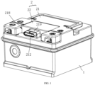
FIG. 1 is a schematic view of a battery case according to an embodiment of the present disclosure. -
FIG. 2 is a schematic view of the battery case (where blocking cover is omitted) according to an embodiment of the present disclosure. -
FIG. 3 is a cross-sectional view of the battery case according to an embodiment of the present disclosure. -
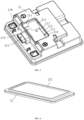
FIG. 4 is a schematic view of a case body and a case cover that are separated from each other according to an embodiment of the present disclosure. -
FIG. 5 is a schematic view of the case cover according to an embodiment of the present disclosure. -
FIG. 6 is a schematic view of the blocking cover according to an embodiment of the present disclosure. -
FIG. 7 is a schematic view of a fastening member according to an embodiment of the present disclosure. - 1, case body; 11, cavity; 12, adhesive slot; 2, case cover; 21, cover body; 211, mounting slot; 212, harness opening; 213, plug docking hole; 214, first slot wall; 215, second slot wall; 216, slot; 217, connection hole; 218, notch; 219, plug docking block; 22, blocking cover; 221, rib; 3, connection harness; 31, harness plug; 4, BMS assembly; 5, fastening member; 51, fastening body; 52, connection portion.
- Technical solutions of the embodiments of the present disclosure will be described in further detail in the following by referring to the accompanying drawings. Obviously, the described embodiments are only a part of but not all of the embodiments of the present disclosure. All other embodiments, which are obtained by any ordinary skilled person in the art based on the embodiments in the present disclosure without any creative work, shall fall within the scope of the present disclosure.
- In the description of the present disclosure, unless otherwise expressly specified and limited, the terms "interconnected", "connected", and "fixed" shall be understood in a broad sense. For example, connection may be fixed connection, detachable connection or connection into a one-piece structure; or may be mechanical connection or electrical connection; or may be direct connection or indirect connection through an intermediate medium; or may be internal communication between two elements or interaction between two elements. Any ordinary skilled person in the art shall understand specific meanings of the above terms in the present disclosure case by case.
- As shown in
FIG. 1 to FIG. 4 , the present disclosure provides a battery case including a case portion and ablocking cover 22. The case portion defines acavity 11 therein. ABMS assembly 4 is received in thecavity 11. An outer wall of the case portion is recessed to define amounting slot 211. A wall of themounting slot 211 defines aharness opening 212 which allows theconnection harness 3 to pass through and is communicated with thecavity 11. The case portion further defines aplug docking hole 213 communicated with themounting slot 211. Aharness plug 31 is received in theplug docking hole 213. Theharness plug 31 is connected to theBMS assembly 4 via theconnection harness 3. An end of theconnection harness 3 is connected to theBMS assembly 4, and the other end of theconnection harness 3 is arranged with theharness plug 31. Theharness plug 31 extends through the harness opening 212 to be inserted into theplug docking hole 213. The blockingcover 22 blocks an opening of themounting slot 211. By defining themounting slot 211 and the harness opening 212 in the case portion, theconnection harness 3 and theBMS assembly 4 may be connected to each other firstly, and subsequently, theharness plug 31 of theconnection harness 3 extends through the harness opening 212 to be inserted into theplug docking hole 213. In this way, when the battery case is being assembled, blind insertion may be avoided. Difficulty of assembling the battery case may be reduced. A hand of an operator may be prevented from touching glue by mistake. Assembling quality of the battery case may be improved. Theconnection harness 3 may be collected inside themounting slot 211, such that theconnection harness 3 is prevented from binding with other structures of the battery case. By arranging the blockingcover 22, the blockingcover 22 may block the mountingslot 211, such that the mountingslot 211 and thecavity 11 are isolated from the external environment, airtightness of the battery case is ensured. - For example, the case portion includes a
case body 1 and acover body 21. Thecavity 11 is defined in thecase body 1. Thecover body 21 is connected to thecase body 1 and to seal thecavity 11. The mountingslot 211 and theplug docking hole 213 are both defined in thecover body 21. In the present embodiment, thecover body 21 and the blockingcover 22 are connected to each other to form thecase cover 2. By arranging thecase body 1 and thecover body 21, the case portion is formed by combining thecase body 1 with thecover body 21, such that theBMS assembly 4 may be mounted easily, and the difficulty of assembling the battery case may be reduced. - As shown in
FIG. 2 , for example, the mountingslot 211 has afirst slot wall 214. Theharness opening 212 is defined in a slot bottom of the mountingslot 211 and extends from the slot bottom to thefirst slot wall 214. By defining the harness opening 212 to extend from the slot bottom of the mountingslot 211 to thefirst slot wall 214, a size of theharness opening 212 may be increased by using a space in a vertical direction, such that theharness plug 31 is facilitated to pass through theharness opening 212, and the battery case is assembled easily. - For example, the mounting
slot 211 further includes asecond slot wall 215. Thesecond slot wall 215 is connected to thefirst slot wall 214. Theharness opening 212 extends to thesecond slot wall 215. That is, in the present embodiment, theharness opening 212 is defined in a position where thefirst slot wall 214, thesecond slot wall 215, and the slot bottom of the mountingslot 211 are connected to each other and extends to reach thefirst slot wall 214, thesecond slot wall 215, and the slot bottom of the mountingslot 211. In this way, the space in the vertical direction is used optimally to increase the size of theharness opening 212, and the difficulty of assembling the BMS is reduced. In the present embodiment, a size of the mountingslot 211 is 88mm*48mm*21.5mm, and the size of theharness opening 212 is 35 mm. - For example, a side of the
cover body 21 is recessed to define anotch 218. The mountingslot 211 is located adjacent to thenotch 218. Aplug docking block 219 is protruding from an inner wall of thenotch 218. Theplug docking hole 213 extends through theplug docking block 219. In order to ensure connection stability of theharness plug 31, theplug docking hole 213 needs to have a certain depth to secure theharness plug 31. The harness plug 31 is further configured to connect to an external device. Therefore, a certain connection space is to be defined at a peripheral portion of theharness plug 31. By defining thenotch 218, a connection space that allows theharness plug 31 to be connected to the external device is provided. In addition, theplug docking block 219 may be received in thenotch 218, such that theplug docking block 219 is prevented from protruding out of the side of thecase cover 2. In this way, a probability that theplug docking block 219 is collided with any external element is reduced, and theharness plug 31 may be less likely to be damaged due to collision. - For example, a
fastening member 5 is received in the mountingslot 211. Thefastening member 5 is configured to secure theconnection harness 3. In the present embodiment, theconnection harness 3 is collected in the mountingslot 211. By arranging thefastening member 5 inside the mountingslot 211, thefastening member 5 may secure theconnection harness 3 inside the mountingslot 211, and theconnection harness 3 is prevented from shaking and generating noise. - As shown in
FIG. 7 , thefastening member 5 includes afastening body 51 and aconnection portion 52 connected to thefastening body 51. Thefastening body 51 defines a harness groove (not shown in the drawings). Theconnection harness 3 in the mountingslot 211 may be secured by the harness groove and thefastening body 51. When thefastening member 5 is connected to the wall of the mountingslot 211, theconnection harness 3 may be secured to the mounting slot. In the present embodiment, thefastening member 5 and thecover body 21 are detachably connected to each other. As shown inFIG. 5 , for example, aconnection hole 217 is defined in a wall of the mountingslot 211, and theconnection portion 52 is inserted in theconnection hole 217. Since thefastening member 5 and thecover body 21 are detachably connected to each other, a position at which thefastening member 5 is arranged and the number offastening members 5 may be adjusted according to demands, such that theconnection harness 3 may be secured easily. Theconnection portion 52 has a simple structure, and thefastening body 51 is fixed in theconnection hole 217 by theconnection portion 52. In this way, difficulty of assembling thefastening member 5 with thecover body 21 may be reduced, and a manufacturing cost of thefastening member 5 may be reduced, and therefore, a cost of the battery case may be reduced. In the present embodiment, theconnection portion 52 is arranged with a disk-shaped member. When theconnection portion 52 is inserted into theconnection hole 217, the disk-shaped member tightly abuts against a surface of thecover body 21 to prevent thefastening member 5 from falling off from thecover body 21. In the present embodiment, theconnection hole 217 is defined in the slot bottom of the mountingslot 211. In this case, thefastening member 5 is fastened at the slot bottom of the mountingslot 211. In other embodiments, thefastening member 5 may be mounted on the slot wall or the slot bottom of the mountingslot 211 by screws. Connection between the fasteningmember 5 and thecover body 21 may be determined according to demands in practice. - In the present embodiment, the blocking
cover 22 and thecover body 21 are fixed to each other by laser welding. A size of the blockingcover 22 is larger than a size of the opening of the mountingslot 211. The welding is performed along a circumference of the blockingcover 22. A gap between the blockingcover 22 and thecover body 21 is sealed. In this way, the airtightness of the battery case is ensured. - As shown in
FIG. 6 , for example, the blockingcover 22 is arranged with arib 221. By arranging therib 221, strength of the blockingcover 22 may be increased, and the blockingcover 22 may be prevented from being deformed. - For example, the
rib 221 is disposed on a side of the blockingcover 22 near thecover body 21 and arranged to form a loop. As shown inFIG. 2 , thecover body 21 defines one loop ofslot 216 around the mountingslot 211. Therib 221 is inserted into theslot 216. By arranging one loop of therib 221 on the blockingcover 22, i.e., arranging therib 221 at the welding position of the blockingcover 22, deformation of the blockingcover 22 caused by welding may be reduced. By defining theslot 216, a space for receiving therib 221 is provided, such that an upper surface of the blockingcover 22 may be aligned with an upper surface of thecover body 21, and an outer appearance of the battery case may be improved. In the present embodiment, theslot 216 is a welding slot and is further configured to be sealed to and welded with the blockingcover 22. - In the present embodiment, the
case body 1 and thecase cover 2 are fixed to each other by an adhesive. As shown inFIGS. 3 and 4 , thecase body 1 defines anadhesive slot 12 at a periphery of thecase body 1. Thecase cover 2 is inserted into theadhesive slot 12 to be fixed with thecase body 1 by the adhesive. - The present embodiment further provides a battery pack including the battery case as described above. Due to the good quality of the battery case provided in the present embodiment, the battery case of the present embodiment may operate in a safe environment. The battery case may be facilitated to control and manage a battery module arranged in the battery pack, and safety performance of the battery pack may be improved.
- In the description herein, it is to be understood that the terms "up", "down", "left", "right", and other orientation or positional relationships are based on orientation or positional relationships shown in the accompanying drawings. The terms are used for ease of description and to simplicity operations, but shall not be interpreted as indicating or implying that the device or the element referred to must be constructed and operated in the described orientation. Therefore, the terms shall not be interpreted as limitations of the present disclosure. In addition, the terms "first" and "second" are used only to descriptively distinguish features and have no special meaning.
- In the description of the present disclosure, the terms "an embodiment", "example", and so on are intended to mean that a specific feature, structure, material, or property described in an embodiment or example is included in at least one embodiments or examples of the present disclosure. In the present specification, schematic representations of the above terms do not necessarily refer to a same one embodiment or example.
- In addition, it should be understood that, although the present disclosure is described in accordance with embodiments, each embodiment may not include only one independent technical solution. The specification is recited in such a manner merely for clarity. Any ordinary skilled person in the art shall take the specification as a whole, and technical solutions in various embodiments may be appropriately combined with each other to form other embodiments that can be understood by any ordinary skilled person in the art.
Claims (20)
- A battery case, comprising a case portion,
wherein, the case portion defines a cavity; a battery management system assembly, BMS assembly, is received in the cavity; the battery case further comprises a blocking cover; an outer wall of the case portion is recessed to define a mounting slot; the case portion further defines a plug docking hole communicated with the mounting slot; a harness plug is received in the plug docking hole; the harness plug is connected to the BMS assembly via the connection harness; a wall of the mounting slot defines a harness opening which allows the connection harness to pass through and is communicated with the cavity; the blocking cover blocks an opening of the mounting slot. - The battery case according to claim 1, wherein, the case portion comprises a case body and a cover body; the cavity is defined in the case body; the cover body is connected to the case body and to seal the cavity; the mounting slot and the plug docking hole are both defined in the cover body.
- The battery case according to claim 1, wherein, the mounting slot has a first slot wall; the harness opening is defined in a slot bottom of the mounting slot and extends from the slot bottom to the first slot wall.
- The battery case according to claim 3, wherein, the mounting slot further has a second slot wall; the second slot wall is connected to the first slot wall; the harness opening further extends to reach the second slot wall.
- The battery case according to claim 2, wherein, a side of the cover body is recessed to define a notch; the mounting slot is located adjacent to the notch; a plug docking block is protruding from an inner wall of the notch; the plug docking hole extends through the plug docking block.
- The battery case according to claim 1, wherein a fastening member is received in the mounting slot; the fastening member is configured to secure the connection harness.
- The battery case according to claim 6, wherein the fastening member and the cover body are detachably connected to each other.
- The battery case according to claim 7, wherein a connection hole is defined in a wall of the mounting slot; the fastening member comprises a fastening body and a connection portion connected to the fastening body; the fastening body defines a harness groove, the connection harness is snapped in the harness groove, the connection portion is inserted in connection hole.
- The battery case according to claim 1, wherein the blocking cover is arranged with a rib.
- The battery case according to claim 9, wherein the rib is disposed on a side of the blocking cover near the cover body, the cover body defines one loop of slot around the mounting slot, and the rib is inserted into the slot.
- The battery case according to claim 1, wherein the blocking cover is welded to the case portion.
- A battery pack, comprising a battery case, wherein, the battery case comprises a case portion, the case portion defines a cavity, a battery management system assembly, BMS assembly, is received in the cavity; and
the battery case further comprises a blocking cover; an outer wall of the case portion is recessed to define a mounting slot; the case portion further defines a plug docking hole communicated with the mounting slot; a harness plug is received in the plug docking hole; the harness plug is connected to the BMS assembly via the connection harness; a wall of the mounting slot defines a harness opening which allows the connection harness to pass through and is communicated with the cavity; the blocking cover blocks an opening of the mounting slot. - The battery pack according to claim 12, wherein, the case portion comprises a case body and a cover body; the cavity is defined in the case body; the cover body is connected to the case body and to seal the cavity; the mounting slot and the plug docking hole are both defined in the cover body.
- The battery pack according to claim 12, wherein, the mounting slot has a first slot wall; the harness opening is defined in a slot bottom of the mounting slot and extends from the slot bottom to the first slot wall.
- The battery pack according to claim 14, wherein, the mounting slot further has a second slot wall; the second slot wall is connected to the first slot wall; the harness opening further extends to reach the second slot wall.
- The battery pack according to claim 13, wherein, a side of the cover body is recessed to define a notch; the mounting slot is located adjacent to the notch; a plug docking block is protruding from an inner wall of the notch; the plug docking hole extends through the plug docking block.
- The battery pack according to claim 12, wherein, a fastening member is received in the mounting slot; the fastening member is configured to secure the connection harness.
- The battery pack according to claim 17, wherein, the fastening member and the cover body are detachably connected to each other.
- The battery pack according to claim 18, wherein, a connection hole is defined in a wall of the mounting slot; the fastening member comprises a fastening body and a connection portion connected to the fastening body; the fastening body defines a harness groove, the connection harness is snapped in the harness groove, the connection portion is inserted in connection hole.
- The battery pack according to claim 12, wherein, the blocking cover is arranged with a rib.
Applications Claiming Priority (2)
| Application Number | Priority Date | Filing Date | Title |
|---|---|---|---|
| CN202220344617.5U CN216928817U (en) | 2022-02-21 | 2022-02-21 | Battery boxes and packs |
| PCT/CN2022/098302 WO2023155340A1 (en) | 2022-02-21 | 2022-06-13 | Battery box and battery pack |
Publications (2)
| Publication Number | Publication Date |
|---|---|
| EP4395035A1 true EP4395035A1 (en) | 2024-07-03 |
| EP4395035A4 EP4395035A4 (en) | 2025-08-13 |
Family
ID=82267014
Family Applications (1)
| Application Number | Title | Priority Date | Filing Date |
|---|---|---|---|
| EP22926650.7A Pending EP4395035A4 (en) | 2022-02-21 | 2022-06-13 | BATTERY BOX AND BATTERY PACK |
Country Status (3)
| Country | Link |
|---|---|
| EP (1) | EP4395035A4 (en) |
| CN (1) | CN216928817U (en) |
| WO (1) | WO2023155340A1 (en) |
Family Cites Families (7)
| Publication number | Priority date | Publication date | Assignee | Title |
|---|---|---|---|---|
| JP6113218B2 (en) * | 2015-04-16 | 2017-04-12 | ヤマハ発動機株式会社 | Battery, battery case and electric vehicle |
| CN205086821U (en) * | 2015-09-23 | 2016-03-16 | 北汽福田汽车股份有限公司 | Pencil fixing device , power battery package and electric vehicle |
| KR102362882B1 (en) * | 2018-02-14 | 2022-02-11 | 주식회사 엘지에너지솔루션 | Battery pack connector |
| KR102367375B1 (en) * | 2018-11-14 | 2022-02-23 | 주식회사 엘지에너지솔루션 | Battery pack |
| CN210743999U (en) * | 2019-07-23 | 2020-06-12 | 广州小鹏汽车科技有限公司 | Connecting row fixing support of battery pack, battery pack and vehicle |
| DE102019124874A1 (en) * | 2019-09-16 | 2021-03-18 | Jungheinrich Aktiengesellschaft | Cover module for a battery housing |
| CN215731862U (en) * | 2021-08-30 | 2022-02-01 | 湖北亿纬动力有限公司 | Lithium ion battery module of integrated BMS and battery pack thereof |
-
2022
- 2022-02-21 CN CN202220344617.5U patent/CN216928817U/en active Active
- 2022-06-13 EP EP22926650.7A patent/EP4395035A4/en active Pending
- 2022-06-13 WO PCT/CN2022/098302 patent/WO2023155340A1/en not_active Ceased
Also Published As
| Publication number | Publication date |
|---|---|
| CN216928817U (en) | 2022-07-08 |
| WO2023155340A1 (en) | 2023-08-24 |
| EP4395035A4 (en) | 2025-08-13 |
Similar Documents
| Publication | Publication Date | Title |
|---|---|---|
| EP3836297B1 (en) | Secondary battery, battery module, battery pack, device and manufacturing method | |
| EP4601087A1 (en) | Top cover assembly, battery cell, assembling method for battery cell, and electrical device | |
| EP4383473A1 (en) | Female connector, male connector, connector assembly and vehicle-mounted apparatus | |
| CN218215411U (en) | Battery cells, batteries and electrical equipment | |
| EP4343939A1 (en) | Battery and electrical apparatus | |
| EP4395035A1 (en) | Battery box and battery pack | |
| CN220421141U (en) | High-voltage power distribution box, battery and electrical device | |
| EP4723338A1 (en) | Electrical connection assembly, battery pack, and electric apparatus | |
| CN215221956U (en) | Connection structure of motor electric connector and window motor | |
| CN214477692U (en) | Battery pack and power consumption device | |
| EP4181307B1 (en) | Battery cell, battery, electric device, and method for manufacturing battery cell | |
| CN222463110U (en) | Battery case and battery and electric equipment with battery case | |
| CN212033100U (en) | Battery packs and vehicles | |
| CN210707915U (en) | Unmanned aerial vehicle's casing and unmanned aerial vehicle | |
| JP2014044879A (en) | Female connector and card edge connector | |
| CN211980701U (en) | Circuit board, battery, power module and aircraft | |
| CN119133767B (en) | Battery box and battery pack | |
| CN219959283U (en) | Box structure and battery pack | |
| CN119542775B (en) | Battery device and electricity utilization device | |
| CN222532014U (en) | BMS shell and PCBA fixed knot construct | |
| CN113479021A (en) | Lightweight tire pressure monitoring sensor | |
| CN217426967U (en) | BMS casing and battery package | |
| CN222300705U (en) | Battery, battery management system and electric equipment | |
| CN222887901U (en) | Battery and electricity utilization device | |
| CN119419439B (en) | Battery cell support and battery pack |
Legal Events
| Date | Code | Title | Description |
|---|---|---|---|
| STAA | Information on the status of an ep patent application or granted ep patent |
Free format text: STATUS: THE INTERNATIONAL PUBLICATION HAS BEEN MADE |
|
| PUAI | Public reference made under article 153(3) epc to a published international application that has entered the european phase |
Free format text: ORIGINAL CODE: 0009012 |
|
| STAA | Information on the status of an ep patent application or granted ep patent |
Free format text: STATUS: REQUEST FOR EXAMINATION WAS MADE |
|
| 17P | Request for examination filed |
Effective date: 20240327 |
|
| AK | Designated contracting states |
Kind code of ref document: A1 Designated state(s): AL AT BE BG CH CY CZ DE DK EE ES FI FR GB GR HR HU IE IS IT LI LT LU LV MC MK MT NL NO PL PT RO RS SE SI SK SM TR |
|
| DAV | Request for validation of the european patent (deleted) | ||
| DAX | Request for extension of the european patent (deleted) | ||
| A4 | Supplementary search report drawn up and despatched |
Effective date: 20250710 |
|
| RIC1 | Information provided on ipc code assigned before grant |
Ipc: H01M 50/244 20210101ALI20250704BHEP Ipc: H01M 50/298 20210101AFI20250704BHEP Ipc: H01M 50/296 20210101ALI20250704BHEP Ipc: H01M 50/10 20210101ALI20250704BHEP Ipc: H01M 50/20 20210101ALI20250704BHEP Ipc: H01M 50/249 20210101ALI20250704BHEP Ipc: H01R 13/00 20060101ALI20250704BHEP Ipc: H01M 10/42 20060101ALI20250704BHEP Ipc: H01M 50/103 20210101ALI20250704BHEP Ipc: H01M 50/262 20210101ALI20250704BHEP Ipc: H01M 50/271 20210101ALI20250704BHEP Ipc: H01M 50/591 20210101ALI20250704BHEP |