EP4395032A1 - Swappable battery module - Google Patents
Swappable battery module Download PDFInfo
- Publication number
- EP4395032A1 EP4395032A1 EP23796706.2A EP23796706A EP4395032A1 EP 4395032 A1 EP4395032 A1 EP 4395032A1 EP 23796706 A EP23796706 A EP 23796706A EP 4395032 A1 EP4395032 A1 EP 4395032A1
- Authority
- EP
- European Patent Office
- Prior art keywords
- battery pack
- locking member
- battery module
- groove
- module according
- Prior art date
- Legal status (The legal status is an assumption and is not a legal conclusion. Google has not performed a legal analysis and makes no representation as to the accuracy of the status listed.)
- Pending
Links
Images


Classifications
-
- B—PERFORMING OPERATIONS; TRANSPORTING
- B60—VEHICLES IN GENERAL
- B60L—PROPULSION OF ELECTRICALLY-PROPELLED VEHICLES; SUPPLYING ELECTRIC POWER FOR AUXILIARY EQUIPMENT OF ELECTRICALLY-PROPELLED VEHICLES; ELECTRODYNAMIC BRAKE SYSTEMS FOR VEHICLES IN GENERAL; MAGNETIC SUSPENSION OR LEVITATION FOR VEHICLES; MONITORING OPERATING VARIABLES OF ELECTRICALLY-PROPELLED VEHICLES; ELECTRIC SAFETY DEVICES FOR ELECTRICALLY-PROPELLED VEHICLES
- B60L53/00—Methods of charging batteries, specially adapted for electric vehicles; Charging stations or on-board charging equipment therefor; Exchange of energy storage elements in electric vehicles
- B60L53/80—Exchanging energy storage elements, e.g. removable batteries
-
- B—PERFORMING OPERATIONS; TRANSPORTING
- B60—VEHICLES IN GENERAL
- B60K—ARRANGEMENT OR MOUNTING OF PROPULSION UNITS OR OF TRANSMISSIONS IN VEHICLES; ARRANGEMENT OR MOUNTING OF PLURAL DIVERSE PRIME-MOVERS IN VEHICLES; AUXILIARY DRIVES FOR VEHICLES; INSTRUMENTATION OR DASHBOARDS FOR VEHICLES; ARRANGEMENTS IN CONNECTION WITH COOLING, AIR INTAKE, GAS EXHAUST OR FUEL SUPPLY OF PROPULSION UNITS IN VEHICLES
- B60K1/00—Arrangement or mounting of electrical propulsion units
- B60K1/04—Arrangement or mounting of electrical propulsion units of the electric storage means for propulsion
-
- B—PERFORMING OPERATIONS; TRANSPORTING
- B60—VEHICLES IN GENERAL
- B60L—PROPULSION OF ELECTRICALLY-PROPELLED VEHICLES; SUPPLYING ELECTRIC POWER FOR AUXILIARY EQUIPMENT OF ELECTRICALLY-PROPELLED VEHICLES; ELECTRODYNAMIC BRAKE SYSTEMS FOR VEHICLES IN GENERAL; MAGNETIC SUSPENSION OR LEVITATION FOR VEHICLES; MONITORING OPERATING VARIABLES OF ELECTRICALLY-PROPELLED VEHICLES; ELECTRIC SAFETY DEVICES FOR ELECTRICALLY-PROPELLED VEHICLES
- B60L50/00—Electric propulsion with power supplied within the vehicle
- B60L50/50—Electric propulsion with power supplied within the vehicle using propulsion power supplied by batteries or fuel cells
- B60L50/60—Electric propulsion with power supplied within the vehicle using propulsion power supplied by batteries or fuel cells using power supplied by batteries
- B60L50/64—Constructional details of batteries specially adapted for electric vehicles
-
- H—ELECTRICITY
- H01—ELECTRIC ELEMENTS
- H01M—PROCESSES OR MEANS, e.g. BATTERIES, FOR THE DIRECT CONVERSION OF CHEMICAL ENERGY INTO ELECTRICAL ENERGY
- H01M50/00—Constructional details or processes of manufacture of the non-active parts of electrochemical cells other than fuel cells, e.g. hybrid cells
- H01M50/20—Mountings; Secondary casings or frames; Racks, modules or packs; Suspension devices; Shock absorbers; Transport or carrying devices; Holders
- H01M50/204—Racks, modules or packs for multiple batteries or multiple cells
-
- H—ELECTRICITY
- H01—ELECTRIC ELEMENTS
- H01M—PROCESSES OR MEANS, e.g. BATTERIES, FOR THE DIRECT CONVERSION OF CHEMICAL ENERGY INTO ELECTRICAL ENERGY
- H01M50/00—Constructional details or processes of manufacture of the non-active parts of electrochemical cells other than fuel cells, e.g. hybrid cells
- H01M50/20—Mountings; Secondary casings or frames; Racks, modules or packs; Suspension devices; Shock absorbers; Transport or carrying devices; Holders
- H01M50/244—Secondary casings; Racks; Suspension devices; Carrying devices; Holders characterised by their mounting method
-
- H—ELECTRICITY
- H01—ELECTRIC ELEMENTS
- H01M—PROCESSES OR MEANS, e.g. BATTERIES, FOR THE DIRECT CONVERSION OF CHEMICAL ENERGY INTO ELECTRICAL ENERGY
- H01M50/00—Constructional details or processes of manufacture of the non-active parts of electrochemical cells other than fuel cells, e.g. hybrid cells
- H01M50/20—Mountings; Secondary casings or frames; Racks, modules or packs; Suspension devices; Shock absorbers; Transport or carrying devices; Holders
- H01M50/249—Mountings; Secondary casings or frames; Racks, modules or packs; Suspension devices; Shock absorbers; Transport or carrying devices; Holders specially adapted for aircraft or vehicles, e.g. cars or trains
-
- H—ELECTRICITY
- H01—ELECTRIC ELEMENTS
- H01M—PROCESSES OR MEANS, e.g. BATTERIES, FOR THE DIRECT CONVERSION OF CHEMICAL ENERGY INTO ELECTRICAL ENERGY
- H01M50/00—Constructional details or processes of manufacture of the non-active parts of electrochemical cells other than fuel cells, e.g. hybrid cells
- H01M50/20—Mountings; Secondary casings or frames; Racks, modules or packs; Suspension devices; Shock absorbers; Transport or carrying devices; Holders
- H01M50/262—Mountings; Secondary casings or frames; Racks, modules or packs; Suspension devices; Shock absorbers; Transport or carrying devices; Holders with fastening means, e.g. locks
- H01M50/264—Mountings; Secondary casings or frames; Racks, modules or packs; Suspension devices; Shock absorbers; Transport or carrying devices; Holders with fastening means, e.g. locks for cells or batteries, e.g. straps, tie rods or peripheral frames
-
- B—PERFORMING OPERATIONS; TRANSPORTING
- B60—VEHICLES IN GENERAL
- B60K—ARRANGEMENT OR MOUNTING OF PROPULSION UNITS OR OF TRANSMISSIONS IN VEHICLES; ARRANGEMENT OR MOUNTING OF PLURAL DIVERSE PRIME-MOVERS IN VEHICLES; AUXILIARY DRIVES FOR VEHICLES; INSTRUMENTATION OR DASHBOARDS FOR VEHICLES; ARRANGEMENTS IN CONNECTION WITH COOLING, AIR INTAKE, GAS EXHAUST OR FUEL SUPPLY OF PROPULSION UNITS IN VEHICLES
- B60K1/00—Arrangement or mounting of electrical propulsion units
- B60K1/04—Arrangement or mounting of electrical propulsion units of the electric storage means for propulsion
- B60K2001/0455—Removal or replacement of the energy storages
- B60K2001/0477—Removal or replacement of the energy storages from the back
-
- B—PERFORMING OPERATIONS; TRANSPORTING
- B60—VEHICLES IN GENERAL
- B60Y—INDEXING SCHEME RELATING TO ASPECTS CROSS-CUTTING VEHICLE TECHNOLOGY
- B60Y2200/00—Type of vehicle
- B60Y2200/90—Vehicles comprising electric prime movers
- B60Y2200/91—Electric vehicles
-
- H—ELECTRICITY
- H01—ELECTRIC ELEMENTS
- H01M—PROCESSES OR MEANS, e.g. BATTERIES, FOR THE DIRECT CONVERSION OF CHEMICAL ENERGY INTO ELECTRICAL ENERGY
- H01M2220/00—Batteries for particular applications
- H01M2220/20—Batteries in motive systems, e.g. vehicle, ship, plane
Definitions
- a battery swap station comprising the replaceable battery module is provided.
- the present invention relates to a replaceable battery module.
- the electric vehicle according to one example of the present invention comprises the replaceable battery module.
- the battery swap station according to one example of the present invention comprises the replaceable battery module.
- the replaceable battery module may be applied to a light electronic vehicle (LEV) or a battery swap station (also referred to as a 'battery charging station').
- LEV light electronic vehicle
- a battery swap station also referred to as a 'battery charging station'.
- the battery pack (100) may comprise a case (101) and a plurality of secondary battery cells (E) accommodated inside the case (101).
- the outer circumferential surface of the battery pack (100) means the outer circumferential surface (102) of the case (101).
- the battery pack (100) has the width (W1) of the front end (100a) relatively narrower than the width (W2) of the rear end (100b) so as to facilitate entry into the mounting space (210).
- the battery pack (100) may be provided with a handle (130) at the rear end (100b) side.
- the battery pack mounting part (200) comprises a mounting space (210) in which the battery pack (100) is detachably mounted, and a locking jaw (220) locked and fixed to the locking member (220) so that the position of the battery pack (100) mounted in the mounting space (210) is fixed.
- the locking member (120) may pass from one end (220a) of the locking jaw (220) to the other end (220b), and when the passage is completed, it may be locked and fixed to the other end (220b) of the locking jaw (220).
- the locking member (120) may be in contact with at least a portion of the other end (220b) of the locking jaw (220).
- One end (220a) of the locking jaw (220) is positioned adjacent to an entrance through which the battery pack (100) enters the mounting space.
- the locking jaw (220) may be provided such that a thickness (t) of one end (220a) increases along the mounting direction (M) of the battery pack. At this time, the locking member (120) may pass through one end (220a) while sliding in contact with one end (220a) of the locking jaw (220) along the mounting direction (M) of the battery pack.
- the locking member (120) passes from one end (220a) of the locking jaw (220) to the other end (220b), it may be pressed from the locking jaw (220) to move toward the bottom surface (111) of the groove.
- the locking member (120) when the battery pack (100) enters the mounting space (210) along the mounting direction (M), the locking member (120) may be moved in the first direction (h1) by the locking jaw (220), and the locking member (120) may be gradually moved in a direction closer to the bottom surface (111) of the groove (110) by the thickness (t) of the locking jaw (220).
- the locking member (120) may be elastically returned to its original position as the force pressed from the locking jaw (220) is released. As the locking member (120) is elastically returned to its original position, at least a portion may be in contact with the other end (220b) of the locking jaw (220). The contacted portion performs a locking and fixing role.
- one end (220a) of the locking jaw (220) may have an inclined surface, and the locking member (120) may pass through the locking jaw (220) while sliding along the slope of the inclined surface.
- a portion of the locking member (120) in contact with the inclined surface may be rounded.
- the locking member (120) may comprise a head part (121) exposed to the outside of the battery pack (100) to be capable of being locked and fixed with the locking jaw (220), a body part (122) connecting the head part (121) and the bottom surface (111) of the groove (110), and a spring member (123) mounted to the body part (122).
- the spring member (123) may be provided to be compressed when the head part (121) moves toward the bottom surface (111) of the groove (110). That is, when the head part (121) moves in the first direction (h1) by an external force, the spring member (123) is compressed. Conversely, when the external force is released, the head part (121) moves in the second direction (h2) while the spring member (123) is elastically restored.
- the head part (121) may have an approximately rectangular parallelepiped shape, and may be formed so that the corners are rounded.
- the head part (121) is substantially slid along the inclined surface of one end (220a) of the locking jaw (220), which is a portion locked and fixed with the other end (220b) of the locking jaw (220).
- the body part (122) may have a bar shape and may be connected to the center of the head part (121).
- the spring member (123) may be provided to surround the body part (122) so that the body part (122) penetrates the inside.
- the spring member (123) may provide a restoring force that elastically returns to the original position after the head part (121) is pressed and moved.
- the spring member (123) may be a coil spring.
- the groove (110) may also be provided with a rail part guiding the movement of the head part (121).
- the bottom surface (111) of the groove (110) may have a through hole (112) through which the body part (122) passes.
- the through hole (112) may be located at the center of the bottom surface (111) of the groove (110).
- the separation preventing member (400) may be a clip member, for example, a C-clip.
- the body part (122) penetrating the through hole (112) may have a clip groove (124) for which the clip member is inserted.
- the through hole (112) penetrates the outer circumferential surface (102) and the inner circumferential surface (103) of the case (101), and the separation preventing member (400) is disposed on the inner circumferential surface (103).
- the inner circumferential surface (103) of the case (101) surrounds the mounting space (210).
- the coupling release part (230) comprises a push button (231) positioned on an outer circumferential surface (201) of the battery pack mounting part (200), and a rod (232) connected to the push button (231) and having one end which penetrates the outer circumferential surface (201) to be exposed to the mounting space (210).
- a depressed part (202) is formed, where the push button (231) may be disposed within the depressed part (202).
- the rod (232) penetrates the depressed part (202) to extend into the mounting space (210).
- one end of the rod (232) moves the locking member (120) toward the bottom surface (111) of the groove (110). Also, after the locking member (120) is moved toward the bottom surface (111) of the groove (110) by the rod (232), the locking member (120) enables to pass to one end (220a) of the locking jaw (220) from the other end (220b).
- the coupling release part (230) may comprise a spring member (233) mounted on the rod (232).
- the spring member (233) may be mounted in a state surrounding the rod (232) so that the rod (232) penetrates the inside.
- the spring member (233) may provide a restoring force that elastically returns to the original position after the push button (231) is pressed.
- the spring member (233) when the push button (231) is pressed by an external force and the rod (122) moves in the first direction (h1), the spring member (233) is compressed. Conversely, when the external force applied to the push button is released, the rod (122) moves in the second direction (h2) while the spring member (233) is elastically restored.
- the direction (P) in which the push button (231) is pressed may be the same direction as the first direction (h1).
- Figure 8 is a configuration diagram schematically showing an electric vehicle (500) related to one example of the present invention
- Figure 9 is a configuration diagram schematically showing a battery swap station (600) related to one example of the present invention.
- the present invention may be an electric vehicle (500) comprising the above-described replaceable battery module.
- the electric vehicle (500) comprises a battery pack mounting part (200), where a battery pack may be detachably mounted on the battery pack mounting part (200).
- the type of the electric vehicle (500) is not particularly limited if the replaceable battery module may be mounted, which may be a small, medium, or large electric vehicle, and preferably may be a small electric vehicle.
- the small electric vehicle may be exemplified by, for example, an electric scooter, an electric bicycle, or a quick board, and the like.
- the electric vehicle comprising the above-described replaceable battery module has an advantage of shortening a replacement time when replacing an old battery pack with a new battery pack.
- the present invention relates to a battery swap station (600) comprising the above-described replaceable battery module.
- the battery swap station (600) may supply power to the battery pack through the battery pack mounting part (200) to charge the battery pack.
- the battery swap station comprising the above-described replaceable battery module has an advantage that the replacement time consumed when mounting an old battery pack or separating a fully charged battery pack is reduced.
Landscapes
- Engineering & Computer Science (AREA)
- Chemical & Material Sciences (AREA)
- Chemical Kinetics & Catalysis (AREA)
- General Chemical & Material Sciences (AREA)
- Electrochemistry (AREA)
- Transportation (AREA)
- Mechanical Engineering (AREA)
- Power Engineering (AREA)
- Aviation & Aerospace Engineering (AREA)
- Combustion & Propulsion (AREA)
- Life Sciences & Earth Sciences (AREA)
- Sustainable Development (AREA)
- Sustainable Energy (AREA)
- Battery Mounting, Suspending (AREA)
- Arrangement Or Mounting Of Propulsion Units For Vehicles (AREA)
Abstract
Description
- The present invention relates to a replaceable battery module, and an electric vehicle and a battery swap station comprising the same.
- The present application claims the benefit of priority based on
Korean Patent Application No. 10-2022-0050507 dated April 25, 2022 - Light electric vehicle (LEV) markets are proposed as a solution to the problem of traffic congestion and parking shortage in large cities, and their use expands to various fields such as tourist destinations, golf carts, and distribution warehouses.
- A small electric vehicle equipped with a battery pack requires battery charging for driving, but has a disadvantage that it takes a long time to charge the battery.
- Recently, in order to shorten the battery charging time, a battery swap method has been considered. The battery swap method means a method of replacing a used battery with a fully charged battery, and the battery swap method can provide convenience to an electric vehicle driver because the battery can be replaced within a short time.
- It is a problem to be solved by the present invention to provide a replaceable battery module capable of quickly replacing a battery pack through a simple coupling structure, and an electric vehicle and a battery swap station comprising the same.
- In order to solve the above problem, a replaceable battery module related to one example of the present invention comprises a battery pack including a groove formed on an outer circumferential surface and a locking member elastically connected to the bottom surface of the groove, and a battery pack mounting part provided with a mounting space, in which the battery pack is detachably mounted, and a locking jaw which is locked and fixed with the locking member so that the position of the battery pack mounted in the mounting space is fixed.
- Also, when the battery pack is mounted in the mounting space, the locking member may pass from one end of the locking jaw to the other end, and be locked and fixed to the other end of the locking jaw after passing through the locking jaw.
- In addition, the locking member is pressed from the locking jaw upon passing from one end of the locking jaw to the other end, and moved toward the bottom surface of the groove.
- Furthermore, the locking member passes through the locking jaw, and then moves in a direction away from the bottom surface of the groove as the force pressed from the locking jaw is released.
- Also, the locking jaw may be provided such that one end has a thickness increasing along the mounting direction of the battery pack, and the locking member may be provided to pass through one end of the locking jaw while sliding in a state of being in contact with one end.
- In addition, the locking member may comprise a head part exposed to the outside of the battery pack, a body part connecting the head part and the bottom surface of the groove, and a spring member mounted on the body part.
- Furthermore, the bottom surface of the groove has a through hole through which the body part passes.
- Also, the spring member may be provided to be compressed when the head part moves toward the bottom surface of the groove.
- In addition, the locking member may comprise a separation preventing member that is coupled to a portion of the body part penetrating the through hole to prevent separation of the locking member from the groove.
- Furthermore, the battery pack mounting part may comprise a coupling release part for releasing the locking coupling of the locking member when the battery pack is separated from the mounting space.
- The coupling release part may comprise a push button positioned on an outer circumferential surface of the battery pack mounting part, and a rod connected to the push button and having one end which penetrates the outer circumferential surface to be exposed to the mounting space.
- Also, when the push button is pressed in a mounting state of the battery pack, one end of the rod may move the locking member toward the bottom surface of the groove.
- In addition, after the locking member is moved toward the bottom surface of the groove by the rod, the locking member is in a state capable of passing to one end of the locking jaw from the other end. At this time, when a user applies an external force in a direction opposite to the mounting direction of the battery pack, the battery pack may be separated from the battery pack mounting part.
- Furthermore, according to another aspect of the present invention, an electric vehicle comprising the replaceable battery module is provided.
- In addition, according to another aspect of the present invention, a battery swap station comprising the replaceable battery module is provided.
- As described above, according to the replaceable battery module related to at least one example of the present invention, and the electric vehicle and the battery swap station comprising the same, the battery pack can be quickly replaced through a simple coupling structure.
-
-
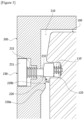
Figure 1 is a cross-sectional diagram of a replaceable battery module according to one example of the present invention. -
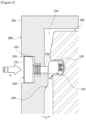
Figures 2 to 4 are operating state diagrams for explaining a process of mounting and separating a battery pack in the replaceable battery module shown inFigure 1 . -
Figures 5 to 7 are diagrams showing the locking member in detail. -
Figure 8 is a configuration diagram schematically showing an electric vehicle related to one example of the present invention. -
Figure 9 is a configuration diagram schematically showing a battery swap station related to one example of the present invention. - Hereinafter, a replaceable battery module according to one example of the present invention, and an electric vehicle and a battery swap station comprising the same will be described in detail with reference to the drawings.
- In addition, regardless of the reference numerals, the same or corresponding components are given by the same or similar reference numerals, duplicate descriptions thereof will be omitted, and for convenience of explanation, the size and shape of each component member as shown can be exaggerated or reduced.
-
Figure 1 is a cross-sectional diagram of a replaceable battery module according to one example of the present invention, andFigures 2 to 4 are operating state diagrams for explaining a process of mounting and separating a battery pack in the replaceable battery module shown inFigure 1 . - Specifically,
Figure 2 is an operating state diagram for explaining a process of mounting a battery pack,Figure 3 is an operating state diagram for explaining a mounting completion state of a battery pack, andFigure 4 is an operating state diagram for explaining a process of separating a battery pack. - The present invention relates to a replaceable battery module. Also, the electric vehicle according to one example of the present invention comprises the replaceable battery module. In addition, the battery swap station according to one example of the present invention comprises the replaceable battery module. In detail, the replaceable battery module may be applied to a light electronic vehicle (LEV) or a battery swap station (also referred to as a 'battery charging station').
- Referring to
Figure 1 , the replaceable battery module related to one example of the present invention comprises a battery pack (100) and a battery pack mounting part (200). The battery pack mounting part (200) may be provided in an electric vehicle, or may be provided in a battery charging station. - The replaceable battery module comprises a battery pack (100) including a groove (110) formed on an outer circumferential surface (102) and a locking member (120) elastically connected to the bottom surface (111) of the groove (110), and a battery pack mounting part (200) provided with a mounting space (210) in which the battery pack (100) is detachably mounted, and a locking jaw (220) which is locked and fixed with the locking member (120) so that the position of the battery pack (100) mounted in the mounting space (210) is fixed.
- The battery pack (100) may comprise a case (101) and a plurality of secondary battery cells (E) accommodated inside the case (101). The outer circumferential surface of the battery pack (100) means the outer circumferential surface (102) of the case (101).
- Also, the battery pack (100) may be electrically connected to the battery pack mounting part (200) in a state of being mounted in the mounting space (210) within the battery pack mounting part (200). As the battery pack (100) and the battery pack mounting part (200) are electrically connected to each other, power is supplied from a battery charging station to the battery pack (100), so that the battery pack may be charged. In addition, the power may be supplied from the battery pack (100) to an electric motor, which is a driving source of an electric vehicle.
- Specifically, the battery pack (100) comprises a groove (110) formed on an outer circumferential surface (102) and a locking member (120) elastically connected to the bottom surface (111) of the groove (110). As the locking member (120) is elastically connected to the bottom surface (111) of the groove (110), it is provided to enable pressing movement toward the bottom surface (111) of the groove (110) and return to its original position.
- The locking member (120) is pressed and moved toward the bottom surface (111) of the groove by an external force, and moved in a direction away from the bottom surface (111) of the groove, when the external force is released, to return to its original position. The external force may be generated by contact with the locking jaw (220) to be described below. At this time, the direction in which the locking member (120) moves toward the bottom surface (111) of the groove (110) is referred to as a first direction (h1), and the direction in which the locking member (120) moves away from the bottom surface (111) of the groove (110) is referred to as a second direction (h2). At this time, the first direction (h1) and the second direction (h2) are directions opposite to each other.
- Also, in the battery pack (100), the width (W1) of the front end (100a) and the width (W2) of the rear end (100b) may be different from each other. The front end (100a) of the battery pack (100) is a part that first enters the mounting space (210) when inserted into the mounting space, and the region in the opposite direction of the front end (100a) is referred to as the rear end (100b).
- Referring to
Figure 1 , the battery pack (100) has the width (W1) of the front end (100a) relatively narrower than the width (W2) of the rear end (100b) so as to facilitate entry into the mounting space (210). In addition, the battery pack (100) may be provided with a handle (130) at the rear end (100b) side. - The battery pack mounting part (200) comprises a mounting space (210) in which the battery pack (100) is detachably mounted, and a locking jaw (220) locked and fixed to the locking member (220) so that the position of the battery pack (100) mounted in the mounting space (210) is fixed.
- Referring to
Figure 2 , when the battery pack (100) is mounted, the locking member (120) may passe from one end (220a) of the locking jaw (220) to the other end (220b), and when the passage is completed, it may be locked and fixed to the other end (220b) of the locking jaw (220). - In a state of being locked and fixed, the locking member (120) may be in contact with at least a portion of the other end (220b) of the locking jaw (220). One end (220a) of the locking jaw (220) is positioned adjacent to an entrance through which the battery pack (100) enters the mounting space.
- The locking jaw (220) may be provided such that a thickness (t) of one end (220a) increases along the mounting direction (M) of the battery pack. At this time, the locking member (120) may pass through one end (220a) while sliding in contact with one end (220a) of the locking jaw (220) along the mounting direction (M) of the battery pack.
- In addition, when the locking member (120) passes from one end (220a) of the locking jaw (220) to the other end (220b), it may be pressed from the locking jaw (220) to move toward the bottom surface (111) of the groove.
- That is, when the battery pack (100) enters the mounting space (210) along the mounting direction (M), the locking member (120) may be moved in the first direction (h1) by the locking jaw (220), and the locking member (120) may be gradually moved in a direction closer to the bottom surface (111) of the groove (110) by the thickness (t) of the locking jaw (220).
- Also, when the passage from one end (220a) of the locking jaw (220) to the other end (220b) is completed, the locking member (120) may be elastically returned to its original position as the force pressed from the locking jaw (220) is released. As the locking member (120) is elastically returned to its original position, at least a portion may be in contact with the other end (220b) of the locking jaw (220). The contacted portion performs a locking and fixing role.
- In addition, one end (220a) of the locking jaw (220) may have an inclined surface, and the locking member (120) may pass through the locking jaw (220) while sliding along the slope of the inclined surface. In order to minimize friction with the inclined surface, a portion of the locking member (120) in contact with the inclined surface may be rounded.
-
Figures 5 to 7 are diagrams showing the locking member (120) in detail. - The locking member (120) may comprise a head part (121) exposed to the outside of the battery pack (100) to be capable of being locked and fixed with the locking jaw (220), a body part (122) connecting the head part (121) and the bottom surface (111) of the groove (110), and a spring member (123) mounted to the body part (122). At this time, the spring member (123) may be provided to be compressed when the head part (121) moves toward the bottom surface (111) of the groove (110). That is, when the head part (121) moves in the first direction (h1) by an external force, the spring member (123) is compressed. Conversely, when the external force is released, the head part (121) moves in the second direction (h2) while the spring member (123) is elastically restored.
- The head part (121) may have an approximately rectangular parallelepiped shape, and may be formed so that the corners are rounded. The head part (121) is substantially slid along the inclined surface of one end (220a) of the locking jaw (220), which is a portion locked and fixed with the other end (220b) of the locking jaw (220).
- In addition, the body part (122) may have a bar shape and may be connected to the center of the head part (121). The spring member (123) may be provided to surround the body part (122) so that the body part (122) penetrates the inside. The spring member (123) may provide a restoring force that elastically returns to the original position after the head part (121) is pressed and moved. As one example, the spring member (123) may be a coil spring. Furthermore, the groove (110) may also be provided with a rail part guiding the movement of the head part (121).
- Referring to
Figures 5 to 7 , the bottom surface (111) of the groove (110) may have a through hole (112) through which the body part (122) passes. The through hole (112) may be located at the center of the bottom surface (111) of the groove (110). - In addition, the locking member (120) may comprise a separation preventing member (400) that is coupled to a portion of the body part (122) penetrating the through hole (112) to prevent separation of the locking member (120) from the groove (110).
- The separation preventing member (400) may be a clip member, for example, a C-clip. The body part (122) penetrating the through hole (112) may have a clip groove (124) for which the clip member is inserted.
- The through hole (112) penetrates the outer circumferential surface (102) and the inner circumferential surface (103) of the case (101), and the separation preventing member (400) is disposed on the inner circumferential surface (103). The inner circumferential surface (103) of the case (101) surrounds the mounting space (210).
- In addition, the battery pack mounting part (200) may comprise a coupling release part (230) for releasing the locking coupling of the locking member (120) when the battery pack (100) is separated from the mounting space.
- Referring to
Figures 2 to 4 , the coupling release part (230) comprises a push button (231) positioned on an outer circumferential surface (201) of the battery pack mounting part (200), and a rod (232) connected to the push button (231) and having one end which penetrates the outer circumferential surface (201) to be exposed to the mounting space (210). On the outer circumferential surface (201) of the battery pack mounting part (200), a depressed part (202) is formed, where the push button (231) may be disposed within the depressed part (202). In addition, the rod (232) penetrates the depressed part (202) to extend into the mounting space (210). - Referring to
Figure 4 , in a state where the battery pack (100) is mounted in the mounting space (210), when the push button (231) is pressed from the outside of the battery pack mounting part (200), one end of the rod (232) moves the locking member (120) toward the bottom surface (111) of the groove (110). As the locking member (120) is moved in the first direction (h1), the locking coupling between the locking member (120) and the locking jaw (220) may be released. - When the push button (231) is pressed in a state of mounting the battery pack (100), one end of the rod (232) moves the locking member (120) toward the bottom surface (111) of the groove (110). Also, after the locking member (120) is moved toward the bottom surface (111) of the groove (110) by the rod (232), the locking member (120) enables to pass to one end (220a) of the locking jaw (220) from the other end (220b).
- In addition, the coupling release part (230) may comprise a spring member (233) mounted on the rod (232). The spring member (233) may be mounted in a state surrounding the rod (232) so that the rod (232) penetrates the inside. The spring member (233) may provide a restoring force that elastically returns to the original position after the push button (231) is pressed.
- Referring to
Figures 3 and4 , when the push button (231) is pressed by an external force and the rod (122) moves in the first direction (h1), the spring member (233) is compressed. Conversely, when the external force applied to the push button is released, the rod (122) moves in the second direction (h2) while the spring member (233) is elastically restored. As one example, the direction (P) in which the push button (231) is pressed may be the same direction as the first direction (h1). - The replaceable battery module according to the present invention may further comprise a cover (not shown) coupled to the battery pack mounting part. The cover is coupled to the battery pack mounting part (200) so that the mounting space (210) of the battery pack mounting part (200) is sealed. The cover prevents the mounted battery pack (100) from being separated, and serves to protect the battery pack (100) from being damaged by external impacts.
-
Figure 8 is a configuration diagram schematically showing an electric vehicle (500) related to one example of the present invention, andFigure 9 is a configuration diagram schematically showing a battery swap station (600) related to one example of the present invention. - Referring to
Figure 8 , the present invention may be an electric vehicle (500) comprising the above-described replaceable battery module. The electric vehicle (500) comprises a battery pack mounting part (200), where a battery pack may be detachably mounted on the battery pack mounting part (200). The type of the electric vehicle (500) is not particularly limited if the replaceable battery module may be mounted, which may be a small, medium, or large electric vehicle, and preferably may be a small electric vehicle. The small electric vehicle may be exemplified by, for example, an electric scooter, an electric bicycle, or a quick board, and the like. The electric vehicle comprising the above-described replaceable battery module has an advantage of shortening a replacement time when replacing an old battery pack with a new battery pack. - Referring to
Figure 9 , the present invention relates to a battery swap station (600) comprising the above-described replaceable battery module. The battery swap station (600) may supply power to the battery pack through the battery pack mounting part (200) to charge the battery pack. The battery swap station comprising the above-described replaceable battery module has an advantage that the replacement time consumed when mounting an old battery pack or separating a fully charged battery pack is reduced. - The preferred examples of the present invention as described above have been disclosed for illustrative purposes, and those skilled in the art having ordinary knowledge of the present invention will be able to make various modifications, changes, and additions within the spirit and scope of the present invention, and such modifications, changes, and additions should be regarded as falling within the scope of the following claims.
- According to the replaceable battery module related to one example of the present invention, and the electric vehicle and the battery swap station comprising the same, replacement of a battery pack can be quickly performed through a simple coupling structure.
Claims (14)
- A replaceable battery module comprising:a battery pack including a groove formed on an outer circumferential surface and a locking member elastically connected to the bottom surface of the groove; anda battery pack mounting part provided with a mounting space, in which the battery pack is detachably mounted, and a locking jaw which is locked and fixed with the locking member so that the position of the battery pack mounted in the mounting space is fixed.
- The replaceable battery module according to claim 1, wherein when the battery pack is mounted in the mounting space,
the locking member passes from one end of the locking jaw to the other end, and is locked and fixed to the other end of the locking jaw after passing through the locking jaw. - The replaceable battery module according to claim 2, wherein
the locking member is pressed from the locking jaw upon passing from one end of the locking jaw to the other end, and moved toward the bottom surface of the groove. - The replaceable battery module according to claim 3, wherein
the locking member passes through the locking jaw, and then moves in a direction away from the bottom surface of the groove as the force pressed from the locking jaw is released. - The replaceable battery module according to claim 1, whereinthe locking jaw is provided such that one end has a thickness increasing along the mounting direction of the battery pack, andthe locking member passes through one end of the locking jaw while sliding in a state of being in contact with one end.
- The replaceable battery module according to claim 1, whereinthe locking member comprises: a head part exposed to the outside of the battery pack;a body part connecting the head part and the bottom surface of the groove; anda spring member mounted on the body part.
- The replaceable battery module according to claim 6, wherein
the bottom surface of the groove has a through hole through which the body part passes. - The replaceable battery module according to claim 6, wherein
the spring member is provided to be compressed when the head part moves toward the bottom surface of the groove. - The replaceable battery module according to claim 7, wherein
the locking member comprises a separation preventing member that is coupled to a portion of the body part penetrating the through hole to prevent separation of the locking member from the groove. - The replaceable battery module according to claim 1, wherein
the battery pack mounting part comprises a coupling release part for releasing the locking coupling of the locking member when the battery pack is separated from the mounting space. - The replaceable battery module according to claim 10, wherein the coupling release part comprises:a push button positioned on an outer circumferential surface of the battery pack mounting part; anda rod connected to the push button and having one end which penetrates the outer circumferential surface to be exposed to the mounting space, andwhen the push button is pressed in a mounting state of the battery pack, one end of the rod moves the locking member toward the bottom surface of the groove.
- The replaceable battery module according to claim 11, wherein
after the locking member is moved toward the bottom surface of the groove by the rod, the locking member is capable of passing to one end of the locking jaw from the other end. - An electric vehicle comprising the replaceable battery module according to claim 1.
- A battery swap station comprising the replaceable battery module according to claim 1.
Applications Claiming Priority (2)
| Application Number | Priority Date | Filing Date | Title |
|---|---|---|---|
| KR1020220050507A KR20230151169A (en) | 2022-04-25 | 2022-04-25 | Replaceable battery module |
| PCT/KR2023/005421 WO2023211059A1 (en) | 2022-04-25 | 2023-04-21 | Swappable battery module |
Publications (2)
| Publication Number | Publication Date |
|---|---|
| EP4395032A1 true EP4395032A1 (en) | 2024-07-03 |
| EP4395032A4 EP4395032A4 (en) | 2025-04-02 |
Family
ID=88519330
Family Applications (1)
| Application Number | Title | Priority Date | Filing Date |
|---|---|---|---|
| EP23796706.2A Pending EP4395032A4 (en) | 2022-04-25 | 2023-04-21 | Swappable battery module |
Country Status (6)
| Country | Link |
|---|---|
| US (1) | US20240408999A1 (en) |
| EP (1) | EP4395032A4 (en) |
| JP (1) | JP2024536471A (en) |
| KR (1) | KR20230151169A (en) |
| CN (1) | CN221928443U (en) |
| WO (1) | WO2023211059A1 (en) |
Family Cites Families (11)
| Publication number | Priority date | Publication date | Assignee | Title |
|---|---|---|---|---|
| TWI252015B (en) * | 2004-07-16 | 2006-03-21 | Benq Corp | Mobile phone and battery-fixing device |
| JP5593894B2 (en) * | 2009-07-30 | 2014-09-24 | スズキ株式会社 | A battery pack to be attached to and detached from an electric vehicle and an electric vehicle including the battery pack |
| EP2626233B1 (en) * | 2012-02-09 | 2018-05-23 | Honda Motor Co., Ltd. | Terminal base of power supply device for electric vehicle |
| JP5794636B2 (en) * | 2012-02-20 | 2015-10-14 | 本田技研工業株式会社 | Electric vehicle power supply terminal block |
| JP5999914B2 (en) * | 2012-02-09 | 2016-09-28 | 本田技研工業株式会社 | Electric vehicle power supply |
| KR20170111975A (en) * | 2016-03-30 | 2017-10-12 | 엘지전자 주식회사 | Mobile terminal |
| JP6741323B1 (en) * | 2019-11-11 | 2020-08-19 | 祐次 廣田 | Automatic exchange system for EV storage batteries |
| JP7419130B2 (en) * | 2020-03-24 | 2024-01-22 | 株式会社クボタ | electric work vehicle |
| KR102375654B1 (en) * | 2020-04-03 | 2022-03-16 | 숙명여자대학교 산학협력단 | Battery exchanging system and method for electric vehicle |
| KR102332609B1 (en) * | 2020-07-20 | 2021-12-01 | 박경식 | Electric vehicle battery replacement system and method |
| KR102408981B1 (en) | 2020-10-16 | 2022-06-14 | (주)컨트롤웍스 | Method for Creating ND Map and Updating map Using it |
-
2022
- 2022-04-25 KR KR1020220050507A patent/KR20230151169A/en active Pending
-
2023
- 2023-04-21 CN CN202390000132.7U patent/CN221928443U/en active Active
- 2023-04-21 JP JP2024521864A patent/JP2024536471A/en active Pending
- 2023-04-21 EP EP23796706.2A patent/EP4395032A4/en active Pending
- 2023-04-21 US US18/702,946 patent/US20240408999A1/en active Pending
- 2023-04-21 WO PCT/KR2023/005421 patent/WO2023211059A1/en not_active Ceased
Also Published As
| Publication number | Publication date |
|---|---|
| US20240408999A1 (en) | 2024-12-12 |
| KR20230151169A (en) | 2023-11-01 |
| JP2024536471A (en) | 2024-10-04 |
| CN221928443U (en) | 2024-10-29 |
| EP4395032A4 (en) | 2025-04-02 |
| WO2023211059A1 (en) | 2023-11-02 |
Similar Documents
| Publication | Publication Date | Title |
|---|---|---|
| EP2069111B1 (en) | Adapter for a power tool battery pack | |
| US7858219B2 (en) | Locking mechanism of battery pack | |
| EP1726410B1 (en) | Power tool | |
| CN103081283B (en) | Foreign material removing structure for charger | |
| KR101552435B1 (en) | Non-stop battery changing system | |
| JP5523905B2 (en) | Terminal connection structure | |
| CN108963123B (en) | Battery cell securing assembly and method | |
| EP0572189A1 (en) | Battery charging equipment for a cordless telephone | |
| JP2001351592A (en) | Rechargeable power tool | |
| JP5858526B2 (en) | Power tool battery mounting adapter and power tool | |
| US20200295327A1 (en) | Battery mounting unit, electric device, and power supply unit | |
| CN118159487A (en) | Battery holding block for a battery receiving space of a materials handling vehicle and a materials handling vehicle including the battery holding block | |
| US8174236B2 (en) | Battery charging device and battery with the same | |
| EP4395032A1 (en) | Swappable battery module | |
| CN118829554A (en) | Battery guide block for a battery receiving space of a material handling vehicle and a material handling vehicle including the battery guide block | |
| JP2013242992A (en) | Battery pack, and rechargeable electrical equipment system | |
| JP3843369B2 (en) | Robot system | |
| KR200479927Y1 (en) | Handheld device of supporting parts with combine charging | |
| CN1989635A (en) | Battery pack and electric hand machine tool | |
| EP4395031B1 (en) | Replaceable battery module | |
| CN118765257A (en) | Battery display, battery connector, and material handling vehicle including the battery display and battery connector | |
| JP2001229895A (en) | Battery pack and motor tool | |
| EP4318696B1 (en) | Gripper and secondary battery transfer device including the same | |
| KR20230095201A (en) | Replaceable battery module | |
| JP2003175487A5 (en) |
Legal Events
| Date | Code | Title | Description |
|---|---|---|---|
| STAA | Information on the status of an ep patent application or granted ep patent |
Free format text: STATUS: THE INTERNATIONAL PUBLICATION HAS BEEN MADE |
|
| PUAI | Public reference made under article 153(3) epc to a published international application that has entered the european phase |
Free format text: ORIGINAL CODE: 0009012 |
|
| STAA | Information on the status of an ep patent application or granted ep patent |
Free format text: STATUS: REQUEST FOR EXAMINATION WAS MADE |
|
| 17P | Request for examination filed |
Effective date: 20240328 |
|
| AK | Designated contracting states |
Kind code of ref document: A1 Designated state(s): AL AT BE BG CH CY CZ DE DK EE ES FI FR GB GR HR HU IE IS IT LI LT LU LV MC ME MK MT NL NO PL PT RO RS SE SI SK SM TR |
|
| REG | Reference to a national code |
Ref country code: DE Ref legal event code: R079 Free format text: PREVIOUS MAIN CLASS: H01M0050262000 Ipc: B60K0001040000 |
|
| A4 | Supplementary search report drawn up and despatched |
Effective date: 20250304 |
|
| RIC1 | Information provided on ipc code assigned before grant |
Ipc: H01M 50/264 20210101ALN20250226BHEP Ipc: H01M 50/244 20210101ALN20250226BHEP Ipc: H01M 50/204 20210101ALN20250226BHEP Ipc: B60L 50/64 20190101ALN20250226BHEP Ipc: B60L 53/80 20190101ALI20250226BHEP Ipc: H01M 50/249 20210101ALI20250226BHEP Ipc: H01M 50/262 20210101ALI20250226BHEP Ipc: B60K 1/04 20190101AFI20250226BHEP |
|
| DAV | Request for validation of the european patent (deleted) | ||
| DAX | Request for extension of the european patent (deleted) | ||
| STAA | Information on the status of an ep patent application or granted ep patent |
Free format text: STATUS: EXAMINATION IS IN PROGRESS |
|
| 17Q | First examination report despatched |
Effective date: 20251030 |
|
| GRAP | Despatch of communication of intention to grant a patent |
Free format text: ORIGINAL CODE: EPIDOSNIGR1 |
|
| STAA | Information on the status of an ep patent application or granted ep patent |
Free format text: STATUS: GRANT OF PATENT IS INTENDED |
|
| RIC1 | Information provided on ipc code assigned before grant |
Ipc: B60K 1/04 20190101AFI20260129BHEP Ipc: H01M 50/262 20210101ALI20260129BHEP Ipc: H01M 50/249 20210101ALI20260129BHEP Ipc: B60L 53/80 20190101ALI20260129BHEP Ipc: B60L 50/64 20190101ALN20260129BHEP Ipc: H01M 50/204 20210101ALN20260129BHEP Ipc: H01M 50/244 20210101ALN20260129BHEP Ipc: H01M 50/264 20210101ALN20260129BHEP |
|
| INTG | Intention to grant announced |
Effective date: 20260206 |
|
| P01 | Opt-out of the competence of the unified patent court (upc) registered |
Free format text: CASE NUMBER: UPC_APP_0009399_4395032/2026 Effective date: 20260311 |