EP4395029A1 - Cell module, power battery, and electric vehicle - Google Patents
Cell module, power battery, and electric vehicle Download PDFInfo
- Publication number
- EP4395029A1 EP4395029A1 EP22925660.7A EP22925660A EP4395029A1 EP 4395029 A1 EP4395029 A1 EP 4395029A1 EP 22925660 A EP22925660 A EP 22925660A EP 4395029 A1 EP4395029 A1 EP 4395029A1
- Authority
- EP
- European Patent Office
- Prior art keywords
- cylindrical cells
- cell
- adjacent
- tray
- cell pack
- Prior art date
- Legal status (The legal status is an assumption and is not a legal conclusion. Google has not performed a legal analysis and makes no representation as to the accuracy of the status listed.)
- Pending
Links
Images


Classifications
-
- H—ELECTRICITY
- H01—ELECTRIC ELEMENTS
- H01M—PROCESSES OR MEANS, e.g. BATTERIES, FOR THE DIRECT CONVERSION OF CHEMICAL ENERGY INTO ELECTRICAL ENERGY
- H01M50/00—Constructional details or processes of manufacture of the non-active parts of electrochemical cells other than fuel cells, e.g. hybrid cells
- H01M50/20—Mountings; Secondary casings or frames; Racks, modules or packs; Suspension devices; Shock absorbers; Transport or carrying devices; Holders
- H01M50/204—Racks, modules or packs for multiple batteries or multiple cells
- H01M50/207—Racks, modules or packs for multiple batteries or multiple cells characterised by their shape
- H01M50/213—Racks, modules or packs for multiple batteries or multiple cells characterised by their shape adapted for cells having curved cross-section, e.g. round or elliptic
-
- H—ELECTRICITY
- H01—ELECTRIC ELEMENTS
- H01M—PROCESSES OR MEANS, e.g. BATTERIES, FOR THE DIRECT CONVERSION OF CHEMICAL ENERGY INTO ELECTRICAL ENERGY
- H01M10/00—Secondary cells; Manufacture thereof
- H01M10/60—Heating or cooling; Temperature control
- H01M10/61—Types of temperature control
- H01M10/613—Cooling or keeping cold
-
- H—ELECTRICITY
- H01—ELECTRIC ELEMENTS
- H01M—PROCESSES OR MEANS, e.g. BATTERIES, FOR THE DIRECT CONVERSION OF CHEMICAL ENERGY INTO ELECTRICAL ENERGY
- H01M10/00—Secondary cells; Manufacture thereof
- H01M10/60—Heating or cooling; Temperature control
- H01M10/64—Heating or cooling; Temperature control characterised by the shape of the cells
- H01M10/643—Cylindrical cells
-
- H—ELECTRICITY
- H01—ELECTRIC ELEMENTS
- H01M—PROCESSES OR MEANS, e.g. BATTERIES, FOR THE DIRECT CONVERSION OF CHEMICAL ENERGY INTO ELECTRICAL ENERGY
- H01M50/00—Constructional details or processes of manufacture of the non-active parts of electrochemical cells other than fuel cells, e.g. hybrid cells
- H01M50/20—Mountings; Secondary casings or frames; Racks, modules or packs; Suspension devices; Shock absorbers; Transport or carrying devices; Holders
- H01M50/233—Mountings; Secondary casings or frames; Racks, modules or packs; Suspension devices; Shock absorbers; Transport or carrying devices; Holders characterised by physical properties of casings or racks, e.g. dimensions
-
- H—ELECTRICITY
- H01—ELECTRIC ELEMENTS
- H01M—PROCESSES OR MEANS, e.g. BATTERIES, FOR THE DIRECT CONVERSION OF CHEMICAL ENERGY INTO ELECTRICAL ENERGY
- H01M50/00—Constructional details or processes of manufacture of the non-active parts of electrochemical cells other than fuel cells, e.g. hybrid cells
- H01M50/20—Mountings; Secondary casings or frames; Racks, modules or packs; Suspension devices; Shock absorbers; Transport or carrying devices; Holders
- H01M50/244—Secondary casings; Racks; Suspension devices; Carrying devices; Holders characterised by their mounting method
-
- H—ELECTRICITY
- H01—ELECTRIC ELEMENTS
- H01M—PROCESSES OR MEANS, e.g. BATTERIES, FOR THE DIRECT CONVERSION OF CHEMICAL ENERGY INTO ELECTRICAL ENERGY
- H01M50/00—Constructional details or processes of manufacture of the non-active parts of electrochemical cells other than fuel cells, e.g. hybrid cells
- H01M50/20—Mountings; Secondary casings or frames; Racks, modules or packs; Suspension devices; Shock absorbers; Transport or carrying devices; Holders
- H01M50/249—Mountings; Secondary casings or frames; Racks, modules or packs; Suspension devices; Shock absorbers; Transport or carrying devices; Holders specially adapted for aircraft or vehicles, e.g. cars or trains
-
- H—ELECTRICITY
- H01—ELECTRIC ELEMENTS
- H01M—PROCESSES OR MEANS, e.g. BATTERIES, FOR THE DIRECT CONVERSION OF CHEMICAL ENERGY INTO ELECTRICAL ENERGY
- H01M50/00—Constructional details or processes of manufacture of the non-active parts of electrochemical cells other than fuel cells, e.g. hybrid cells
- H01M50/30—Arrangements for facilitating escape of gases
- H01M50/35—Gas exhaust passages comprising elongated, tortuous or labyrinth-shaped exhaust passages
-
- H—ELECTRICITY
- H01—ELECTRIC ELEMENTS
- H01M—PROCESSES OR MEANS, e.g. BATTERIES, FOR THE DIRECT CONVERSION OF CHEMICAL ENERGY INTO ELECTRICAL ENERGY
- H01M50/00—Constructional details or processes of manufacture of the non-active parts of electrochemical cells other than fuel cells, e.g. hybrid cells
- H01M50/30—Arrangements for facilitating escape of gases
- H01M50/35—Gas exhaust passages comprising elongated, tortuous or labyrinth-shaped exhaust passages
- H01M50/358—External gas exhaust passages located on the battery cover or case
-
- H—ELECTRICITY
- H01—ELECTRIC ELEMENTS
- H01M—PROCESSES OR MEANS, e.g. BATTERIES, FOR THE DIRECT CONVERSION OF CHEMICAL ENERGY INTO ELECTRICAL ENERGY
- H01M10/00—Secondary cells; Manufacture thereof
- H01M10/60—Heating or cooling; Temperature control
- H01M10/65—Means for temperature control structurally associated with the cells
- H01M10/655—Solid structures for heat exchange or heat conduction
- H01M10/6556—Solid parts with flow channel passages or pipes for heat exchange
- H01M10/6557—Solid parts with flow channel passages or pipes for heat exchange arranged between the cells
-
- H—ELECTRICITY
- H01—ELECTRIC ELEMENTS
- H01M—PROCESSES OR MEANS, e.g. BATTERIES, FOR THE DIRECT CONVERSION OF CHEMICAL ENERGY INTO ELECTRICAL ENERGY
- H01M10/00—Secondary cells; Manufacture thereof
- H01M10/60—Heating or cooling; Temperature control
- H01M10/65—Means for temperature control structurally associated with the cells
- H01M10/656—Means for temperature control structurally associated with the cells characterised by the type of heat-exchange fluid
- H01M10/6567—Liquids
-
- H—ELECTRICITY
- H01—ELECTRIC ELEMENTS
- H01M—PROCESSES OR MEANS, e.g. BATTERIES, FOR THE DIRECT CONVERSION OF CHEMICAL ENERGY INTO ELECTRICAL ENERGY
- H01M2220/00—Batteries for particular applications
- H01M2220/20—Batteries in motive systems, e.g. vehicle, ship, plane
-
- Y—GENERAL TAGGING OF NEW TECHNOLOGICAL DEVELOPMENTS; GENERAL TAGGING OF CROSS-SECTIONAL TECHNOLOGIES SPANNING OVER SEVERAL SECTIONS OF THE IPC; TECHNICAL SUBJECTS COVERED BY FORMER USPC CROSS-REFERENCE ART COLLECTIONS [XRACs] AND DIGESTS
- Y02—TECHNOLOGIES OR APPLICATIONS FOR MITIGATION OR ADAPTATION AGAINST CLIMATE CHANGE
- Y02E—REDUCTION OF GREENHOUSE GAS [GHG] EMISSIONS, RELATED TO ENERGY GENERATION, TRANSMISSION OR DISTRIBUTION
- Y02E60/00—Enabling technologies; Technologies with a potential or indirect contribution to GHG emissions mitigation
- Y02E60/10—Energy storage using batteries
-
- Y—GENERAL TAGGING OF NEW TECHNOLOGICAL DEVELOPMENTS; GENERAL TAGGING OF CROSS-SECTIONAL TECHNOLOGIES SPANNING OVER SEVERAL SECTIONS OF THE IPC; TECHNICAL SUBJECTS COVERED BY FORMER USPC CROSS-REFERENCE ART COLLECTIONS [XRACs] AND DIGESTS
- Y02—TECHNOLOGIES OR APPLICATIONS FOR MITIGATION OR ADAPTATION AGAINST CLIMATE CHANGE
- Y02T—CLIMATE CHANGE MITIGATION TECHNOLOGIES RELATED TO TRANSPORTATION
- Y02T10/00—Road transport of goods or passengers
- Y02T10/60—Other road transportation technologies with climate change mitigation effect
- Y02T10/70—Energy storage systems for electromobility, e.g. batteries
Definitions
- a size to energy storage volume ratio is an important performance parameter of the power battery.
- the size to energy storage volume ratio is a ratio of the energy storage volume of the battery to the size of the battery.
- the power battery has a poor space utilization rate, resulting in a low size to energy storage volume ratio, which cannot meet a user's demand for an endurance life of an electric vehicle.
- the present disclosure provides a cell pack, which may improve a space utilization rate of the cylindrical cell, to increase the size to energy storage volume ratio of the cell pack to increase an endurance life of a power battery.
- the present disclosure provides a cell pack including a tray and a plurality of cylindrical cells.
- the plurality of cylindrical cells are disposed on the tray.
- the plurality of cylindrical cells are projected onto the tray along a height direction of the cylindrical cells to generate a plurality of projections, and a sum of areas of the plurality of projections is S.
- An area of a projection of the tray along the height direction of the cylindrical cells is A, where S/A 0.67.
- the present disclosure further provides a power battery including a case and the cell pack as described in the above.
- the cell pack is arranged inside the case.
- the present disclosure further provides an electric vehicle including the power battery.
- a first feature being “above” or “under” a second feature may include the first feature directly contacting the second feature; or include the first feature indirectly contacting the second feature through another feature disposed therebetween.
- the first feature being “above”, “on” and “on top of” the second feature may include the first feature being directly above and diagonally above the second feature, or may simply indicate that the first feature is horizontally higher than the second feature.
- the first feature being “below”, “under” and “beneath” the second feature may include the first feature being directly below and diagonally below the second feature, or may simply indicate that the first feature is horizontally lower than the second feature.
- the cell pack 200 further includes a liquid cooling plate 23.
- the liquid cooling plate 23 contacts the cylindrical cells 22.
- the liquid cooling plate 23 may control temperatures of the cylindrical cells 22 by heat exchange to prevent the temperatures of the cylindrical cells 22 from being abnormal.
- each cell pack 200 has N cylindrical cells 22 and each cylindrical cell 22 has a radius of r
- the tray 21 is rectangular, a length of the rectangular tray 21 is C, and a width of the rectangular tray 21 is K.
- the ratio of the S to the A may be 0.7, 0.8, or 0.9.
- cylindrical cells 22 in one row of the two adjacent rows of cell groups 220 are misaligned to cylindrical cells 22 in the other one row of the two adjacent rows of cell groups 220.
- a size of the plurality of rows of cell groups 220 along the second direction Y may be reduced when the cylindrical cells 22 in the two adjacent rows of cell groups 220 are misaligned to each other. In this way, the plurality of cylindrical cells 22 may be arranged more compactly, and therefore, the capacity of the tray 21 for receiving the cylindrical cells 22 may be increased.
- the cylindrical cells 22 adjacent to the first limiting slot wall 2111 are cylindrical cells 22 disposed closest to the first limiting slot wall 2111.
- the tray has two first limiting slot walls 2111.
- the cylindrical cells 22 adjacent to the two first limiting slot walls 2111 are cylindrical cells 22 in the first row of cell groups arranged along the second direction Y and cylindrical cells 22 in the last row of cell groups arranged along the second direction Y.
- a distance L 6 between the second limiting slot wall 2112 and cylindrical cells 22 adjacent to the second limiting slot wall 2112 is not less than 22 mm.
- the distance L 6 between the second limiting slot wall 2112 and the adjacent cylindrical cells 22 is mainly determined based on a size of the pipe joint arranged at an end of the liquid cooling plate 23. It is to be ensured that a space between the cylindrical cells 22 and the second limiting slot wall 2112 is sufficient to receive the pipe joint. It is to be understood that the distance L 6 between the second limiting slot wall 2112 and the adjacent cylindrical cells 22 may be adjusted based on the size of the pipe joint that is used in practice.
- the cylindrical cells 22 adjacent to the second limiting slot wall 2112 are the cylindrical cells 22 disposed closest to the second limiting slot wall 2112.
- the tray 21 has two second limiting slot walls 2112.
- the plurality of rows of cell groups 220 arranged along the second direction Y may be denoted as a first row of cell groups, a second row of cell groups, a third row of cell groups, ... till a twelfth row of cell groups.
- the two second limiting slot wall 2112 are a right second limiting slot wall 2112 and a left second limiting slot wall 2112 arranged along the first direction X.
- the case 100 defines a positioning slot 13, and the tray 21 is received in the positioning slot 13, such that positioning accuracy of the tray 21 may be improved.
- the tray 21 includes a tray body and a fixation flange surrounding a circumference of the tray body.
- the positioning slot 13 is a stepped slot, including an upper slot and a lower slot. A size of the upper slot is larger than a size of the lower slot.
- a tab is arranged on a side wall of the case 100.
- a cross beam 12 and a longitudinal beam 11 are arranged inside the case 100. The cross beam 12 and the longitudinal beam 11 are provided to cross with each other, such that the cross beam 12, the longitudinal beam 11, and the tab cooperatively define the lower slot.
- the cylindrical cells 22 adjacent to the first positioning slot wall 131 are cylindrical cells 22 in the first row of cell groups arranged along the second direction Y and cylindrical cells 22 in the last row of cell groups arranged along the second direction Y.
- a distance L 8 between the second positioning slot wall 132 and cylindrical cells 22 adjacent to the second positioning slot wall 132 is not less than 84.5 mm, so as to reduce difficulty of assembling the case 100 with the tray 21.
- the cylindrical cells 22 adjacent to the second positioning slot wall 132 are cylindrical cells 22 that are disposed closest to the second positioning slot wall 132.
- the plurality of rows of cell groups 220 in the cell pack 200 are denoted as the first row of cell groups, the second row of cell groups, ..., and till the twelfth row of cell groups arranged in the second direction Y.
- the positioning slot has two second positioning slot walls 132, which are a right second positioning slot wall 132 and a left second positioning slot wall 132 along the first direction X.
- the cylindrical cells 22 adjacent to the right second positioning slot wall 132 are first cylindrical cells 22 in even numbered rows of cell groups arranged along the first direction X.
- the cylindrical cells 22 adjacent to the left second positioning slot wall 132 are last cylindrical cells 22 in odd numbered rows of cell groups arranged along the first direction X.
- the distance L 7 between the first positioning slot wall 131 and the adjacent cylindrical cells 22 and the distance L 8 between the second positioning slot wall 132 and the adjacent cylindrical cells 22 may be determined according to demands in practice, such that the structure may be compatible with various models of power batteries.
- the case 100 defines a plurality of positioning slots 13. Each positioning slot 13 receives one cell pack 200.
- the cylindrical cells 22 in the power battery may form a packed structure, such that the number of cell packs 200 may be determined easily based on a model of the power battery, and the power battery may be assembled more flexibly.
- the case 100 defines four positioning slots 13. The four positioning slots 13 are arranged in two rows and two columns. In other embodiments, the number of positioning slots 13 may be determined according to demands in practice.
- a center distance L 9 between two cylindrical cells 22, which are located in two adjacent positioning slots 13 along the first direction X and are arranged directly opposite to each other is not less than 188 mm.
- the value range of the L 9 enables, for the two positioning slots 13 arranged along the first direction X, the tray 21 to have a sufficiently wide edge dimension to allow the tray 21 to be fixed to the case 100 easily.
- the tray 21 includes the fixation flange disposed surrounding the circumference of limiting slot 211. The fixation flange laps over the case 100 and is fixed to the case 100. Since the L 9 is not less than 188 mm, the size of the fixation flange of each of two adjacent trays 21 along the first direction X can be ensured, such that the fixation effect of the tray 21 to the case 100 is improved.
- a center distance L 10 between two adjacent cylindrical cells 22, which are located in two adjacent positioning slots 13 arranged along the second direction Y, is not less than 132 mm. Since the center distance L 10 is not less than 132 mm, the size of the fixation flange of two adjacent trays 21 along the second direction Y can be ensured, such that the fixation effect of the tray 21 to the case 100 is improved.
- a distance between two adjacent cell packs 200 is not less than 5 mm. That is, a distance between two adjacent trays 21 is not less than 5 mm. In this way, mutual interference between the two adjacent trays 21, which may affect fixation of the cell pack 200, may be prevented.
- each of a distance between the cell pack 200 and the positioning slot 13 along the first direction and a distance between the cell pack 200 and the positioning slot 13 along the second direction is not less than 5 mm. That is, a distance between the first side wall 213 of the tray 21 and the first positioning slot wall 131 of the positioning slot 13 is not less than 5 mm; and a distance between the second side wall 214 of the tray 21 and the second positioning slot wall 132 of the positioning slot 13 is not less than 5 mm. In this way, it is ensured that the tray 21 can be smoothly mounted into the positioning slot 13, and assembling difficulty may be reduced.
- the case 100 defines a cell mounting cavity b and an element mounting cavity a.
- the cell pack 200 is received in the cell mounting cavity b.
- the element mounting cavity a is configured to receive other electrical parts of the power battery.
- the cell mounting cavity b and the element mounting cavity a are arranged along the first direction X.
- the tray 21 is spaced apart from a bottom surface of the case 100 to form a pressure relief cavity 14.
- the case 100 further defines an air vent communicated with the pressure relief cavity 14.
- the tray 21 defines with a through hole 212 that is directly facing an end of the cylindrical cell 22 and is communicating with the pressure relief cavity 14.
- an explosion-proof valve at a bottom of the cylindrical cell 22 opens, gases and ejections generated in the cylindrical cell 22 enter the pressure relief cavity 14 through the through hole 212 and are further discharged from the air vent. In this way, the cylindrical cell 22 is prevented from combustion or explosion.
- a certain height is to be defined between the bottom of the cylindrical cell 22 and the bottom surface of the pressure relief cavity 14 to reduce a gas releasing pressure and to improve a gas releasing speed.
- a sum of a depth H 1 of the through hole 212 and a height H 2 of the pressure relief cavity 14 is not less than 6 mm to ensure a gas releasing effect of the power battery, such that the gases generated by the thermal-runaway cylindrical cell 22 may be discharged rapidly, and safety of the power battery may be improved.
- the depth H 1 of the through hole 212 is in a range of 2mm-10mm, such as 3mm, 4mm, 5mm, 6mm, 7mm, 8mm or 9mm.
- the height H 2 of the pressure relief cavity 14 is in a range from 2mm-10mm, such as 3mm, 4mm, 5mm, 6mm, 7mm, 8mm or 9mm.
- the height of the cell pack 200 is in a range from 90mm- 130mm, such as 95mm, 100mm, 115mm, 120mm, or 125mm. This height range satisfies heights of various conventional cylindrical cells 22 available in the art.
- the height of the power battery is in a range from 100mm-150mm, such as 105mm, 110mm, 115mm, 120mm, 125mm, 130mm, 135mm, 140mm or 145mm.
- a length of the cell pack 200 is in a range from 500mm-1000mm, such as 600mm, 700mm, 800mm, 900mm or 950mm.
- a length of the power battery is in a range from 1300mm-2300mm, such as 1400mm, 1500mm, 1600mm, 1700mm, 1800mm, 1900mm, 2000mm, 2100mm or 2200mm.
- a width of the cell pack 200 is in a range from 500mm- 1000mm, such as 600mm, 700mm, 800mm, 900mm or 950mm.
- a width of the power battery is in a range from 1300mm-2300mm, such as 1400mm, 1500mm, 1600mm, 1700mm, 1800mm, 1900mm, 2000mm , 2100mm or 2200mm.
- the present embodiment further provides an electric vehicle including the cell pack described above.
- the electric vehicle is arranged with the above-described cell pack. Therefore, when a certain one cylindrical cell 22 is having the thermal runaway, the thermal runaway is prevented from spreading to other cylindrical cells 22, and thermal runaway of the entire cell pack can be prevented.
- the electric vehicle is arranged with the above-described cell pack, the endurance life of the electric vehicle is improved, the user's demands can be satisfied, and the user's satisfaction can be improved.
Landscapes
- Chemical & Material Sciences (AREA)
- Chemical Kinetics & Catalysis (AREA)
- Electrochemistry (AREA)
- General Chemical & Material Sciences (AREA)
- Engineering & Computer Science (AREA)
- Aviation & Aerospace Engineering (AREA)
- Manufacturing & Machinery (AREA)
- Battery Mounting, Suspending (AREA)
Abstract
Description
- The present application claims priority of the
Chinese patent application No. 202220281117.1, filed on February 11, 2022 - The present disclosure relates to the field of power batteries, and in particular to a cell pack , a power battery, and an electric vehicle.
- In recent years, new energy vehicles are developing dramatically, especially those are powered by lithium batteries. In the lithium batteries, cylindrical cells are widely used in power systems. Since each cylindrical cell has a small power capacity, one series of cells may have a large number of cells.
- A size to energy storage volume ratio is an important performance parameter of the power battery. The size to energy storage volume ratio is a ratio of the energy storage volume of the battery to the size of the battery. In the art, the power battery has a poor space utilization rate, resulting in a low size to energy storage volume ratio, which cannot meet a user's demand for an endurance life of an electric vehicle.
- The present disclosure provides a cell pack, which may improve a space utilization rate of the cylindrical cell, to increase the size to energy storage volume ratio of the cell pack to increase an endurance life of a power battery.
- The present disclosure provides a cell pack including a tray and a plurality of cylindrical cells. The plurality of cylindrical cells are disposed on the tray. The plurality of cylindrical cells are projected onto the tray along a height direction of the cylindrical cells to generate a plurality of projections, and a sum of areas of the plurality of projections is S. An area of a projection of the tray along the height direction of the cylindrical cells is A, where S/A 0.67.
- The present disclosure further provides a power battery including a case and the cell pack as described in the above. The cell pack is arranged inside the case.
- The present disclosure further provides an electric vehicle including the power battery.
-
-
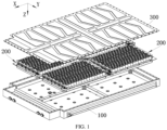
FIG. 1 is an explosive view of a power battery according to an embodiment of the present disclosure. -
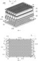
FIG. 2 is an explosive view of a cell pack according to an embodiment of the present disclosure. -
FIG. 3 is a top view of a tray assembled with the cell according to an embodiment of the present disclosure. -
FIG. 4 is a top view of a case according to an embodiment of the present disclosure. -
FIG. 5 is a top view of a partial structure of the power battery according to an embodiment of the present disclosure. -
FIG. 6 is a cross-sectional view of a partial structure of the power battery according to an embodiment of the present disclosure. - 100, case; 11, longitudinal beam; 12, cross beam; 13, positioning slot; 131, first positioning slot wall; 132, second positioning slot wall; 14, pressure relief cavity; 200, cell pack; 21, tray; 211, limiting slot; 2111, first limiting slot wall; 2112, second limiting slot wall; 212, through hole; 213, first side wall; 214, second side wall; 220, cell group; 22, cylindrical cell; 23, liquid cooling plate; 24, integration assembly; 25, polyurethane foam layer; 26, structural adhesive layer; 300, upper cover;
a, element mounting cavity; b, cell mounting cavity; X, first direction; Y, second direction. - The present disclosure is described below by referring to the accompanying drawings and embodiments. It will be understood that the specific embodiments described herein are for the purpose of explaining the present disclosure only. To be noted that, for ease of description, only portions relevant to the present disclosure, instead of all structures, are shown in the accompanying drawings.
- In the description of the present disclosure, unless otherwise expressly specified, the terms "inter-connected", "connected", and "fixed" shall be understood broadly. For example, connection may be fixed connection, detachable connection, integration into a one-piece structure; or may be mechanical connection or electrical connection; or may be direct connection or indirect connection through an intermediate medium; or may be internally connection between two elements or interaction between two elements. Any ordinary skilled person in the art shall understand specific meanings of the above terms in the present disclosure case by case.
- In the description of the present disclosure, unless otherwise expressly specified, a first feature being "above" or "under" a second feature may include the first feature directly contacting the second feature; or include the first feature indirectly contacting the second feature through another feature disposed therebetween. In addition, the first feature being "above", "on" and "on top of" the second feature may include the first feature being directly above and diagonally above the second feature, or may simply indicate that the first feature is horizontally higher than the second feature. The first feature being "below", "under" and "beneath" the second feature may include the first feature being directly below and diagonally below the second feature, or may simply indicate that the first feature is horizontally lower than the second feature.
- In the description of the present disclosure, the terms "up", "down", "right", and other orientations or positional relationships refer to orientations or positional relationships shown in the accompanying drawings. The orientations or positional relationships are used only to facilitate description and to simplify operations, but do not indicate or imply that a device or an element referred to must be oriented, arranged and operated in a particular orientation. Furthermore, the terms "first" and "second" are used to distinguish various features descriptively but do not have special meanings.
- As shown in
FIG. 1 , the present embodiment provides a power battery including acase 100, acell pack 200, and anupper cover 300. A top of thecase 100 has an opening. Theupper cover 300 is fixed to thecase 100 to cooperatively define an inner cavity to receive thecell pack 200. As shown inFIG. 2 , thecell pack 200 includes atray 21 and a plurality of rows ofcell groups 220. Thecell groups 220 are disposed on thetray 21. Each row of thecell groups 220 includes a plurality ofcylindrical cells 22. In the present embodiment, eachcylindrical cell 22 is cylindrical. Thecylindrical cell 22 is vertically disposed on thetray 21 to improve stability of thecylindrical cells 22 when being disposed on thetray 21. - The
cell pack 200 further includes anintegration assembly 24, arranged above thecylindrical cells 22 to enable the plurality ofcylindrical cells 22 to be connected to each other in parallel and in series. - In an embodiment, the
cell pack 200 further includes aliquid cooling plate 23. Theliquid cooling plate 23 contacts thecylindrical cells 22. Theliquid cooling plate 23 may control temperatures of thecylindrical cells 22 by heat exchange to prevent the temperatures of thecylindrical cells 22 from being abnormal. - In order to reduce the number of
liquid cooling plates 23, every two adjacent rows of the plurality of rows ofcell groups 220 form one set. For each set, oneliquid cooling plate 23 is disposed between the two adjacent rows ofcell groups 220. - In some embodiments, a plurality of
liquid cooling plates 23 are connected to each other by pipe joints, such that heat exchanging medium may be injected into the plurality ofliquid cooling plates 23, and a piping structure is simplified. - In some embodiments, the
cell pack 200 further includes apolyurethane foam layer 25 and a structuraladhesive layer 26. Each of thepolyurethane foam layer 25 and the structuraladhesive layer 26 sleeves an outside of eachcylindrical cell 22 to fill a gap between every two adjacentcylindrical cells 22 and to provide a cushioning effect to thecell pack 200. - In some embodiments, a portion of each
liquid cooling plate 23 is embedded in thepolyurethane foam layer 25 to improve a fixing effect of theliquid cooling plate 23. - In order to improve an endurance life of the power battery, the plurality of
cylindrical cells 22 are projected onto thetray 21 along a height direction of thecylindrical cells 22 to generate a plurality of projections, a sum of areas of the plurality of projections is S; and an area of a projection of thetray 21 along the height direction of thecylindrical cells 22 is A, where S/A≥ 0.67. By controlling the ratio of the sum of the areas of the plurality of projections of the plurality ofcylindrical cells 22 to the area of the projection of thetray 21 along the height direction of thecylindrical cells 22, space occupation of thecylindrical cells 22 in thecell pack 200 may be increased without changing a height of thecylindrical cell 22. In this way, the size to energy storage volume ratio of thecylindrical cell 22 may be ensured, and the endurance life of the power battery may be ensured. - It is understood that, in a case that each
cell pack 200 has Ncylindrical cells 22 and eachcylindrical cell 22 has a radius of r, the sum S of the areas of the projections of the plurality ofcylindrical cells 22 onto thetray 21 satisfies: S=Nπr2. Thetray 21 is rectangular, a length of therectangular tray 21 is C, and a width of therectangular tray 21 is K. In this case, the area A of the projection of thetray 21 along the height direction of thecylindrical cells 22 satisfies: S/A= Nπr2/CK. - In the present embodiment, the radius r of the
cylindrical cell 22 is 23 mm, the number N of thecylindrical cells 22 in eachcell pack 200 is 180, the length C of thetray 21 is 786 mm, and the width of thetray 21 is 504 mm. In this case, the ratio of the S to the A is 0.75. - Exemplarily, the ratio of the S to the A may be 0.7, 0.8, or 0.9.
- In an embodiment, a sum of volumes of the plurality of
cylindrical cells 22 is V1, and a product of the area of the projection of thetray 21 along the height direction of thecylindrical cells 22 multiplied by the height of thecell pack 200 is V2. In this case, V1/V2=0.6 to 0.75. Within the volume ratio range, the space occupation ofcylindrical cells 22 in thecell pack 200 is ensured. In this way, the size to energy storage volume ratio of thecell pack 200 is ensured, and the endurance life of the power battery may be ensured. Exemplarily, the ratio of V1 to V2 may be 0.64, 0.65, 0.67, 0.7, or 0.72. - In the present embodiment, the height H3 of the
cell pack 200 is 104 mm, and the height H4 of thecylindrical cell 22 is 96.63 mm. Since V1= Nar2H3 and V2= CKH4, the ratio of V1 to V2 is 0.7. - In some embodiments, the ratio of V1 to V2 is 0.64. With the ratio of 0.64, the space within the
cell pack 200 can be optimally utilized, and a waste of space can be avoided. - In addition, by controlling the ratio of S to A and the ratio of V1 to V2, a side of each
cylindrical cell 22 has a larger surface area, facilitating heat dissipation from eachcylindrical cell 22, preventing theoverall cell pack 200 from having an excessively high temperature. - As shown in
FIG. 3 , thetray 21 is rectangular. Therectangular tray 21 includes afirst side wall 213 and asecond side wall 214 adjacent to thefirst side wall 213. Thefirst side wall 213 extends along a first direction X, and thesecond side wall 214 extends along a second direction Y. The first direction X is perpendicular to the second direction Y. A distance L1 between thefirst side wall 213 andcylindrical cells 22 adjacent to thefirst side wall 213 is not less than 60 mm, such as 65 mm, 70 mm, or 75 mm. A distance L2 between thesecond side wall 214 and thecylindrical cells 22 adjacent to thesecond side wall 214 is not less than 80 mm, such as 85 mm, 90 mm, or 95 mm. When the distance L1 between thefirst side wall 213 and the adjacentcylindrical cells 22 and the distance L2 between thesecond side wall 214 and the adjacentcylindrical cells 22 satisfy the above distance ranges, thetray 21 may be fixedly arranged in thecase 100 easily, and thetray 21 may be assembled with thecase 100 in a power battery having a common specification. - To be noted that, the
cylindrical cells 22 adjacent to thefirst side wall 213 are thecylindrical cells 22 disposed closest to thefirst side wall 213. As shown inFIG. 3 , thetray 21 includes twofirst side walls 213, and thecylindrical cells 22 adjacent to the twofirst side walls 213 are the first row ofcylindrical cells 22 arranged in the second direction Y and the last row ofcylindrical cells 22 arranged in the second direction Y. - The
cylindrical cells 22 adjacent to thesecond side wall 214 are thecylindrical cells 22 disposed closest to thesecond side wall 214. As shown inFIG. 3 , thetray 21 includes twosecond side walls 214, and thecylindrical cells 22 adjacent to the twosecond side walls 214 are the first row ofcylindrical cells 22 arranged in the first direction X and the last row ofcylindrical cells 22 arranged in the first direction X. - In the present embodiment, the plurality of
cylindrical cells 22 in each row ofcell group 220 are arranged along the first direction X. The plurality of rows ofcell groups 220 are arranged along the second direction Y. In each row ofcell groups 220, a distance L3 between two adjacentcylindrical cells 22 is not less than 1 mm, such that the adjacentcylindrical cells 22 satisfy a minimum insulation requirement. Moreover, the distance L3 between the two adjacentcylindrical cells 22 may be adjusted based on a size of thetray 21 along the first direction X and the number ofcylindrical cells 22 to be received in thetray 21. In this way, the structure may be compatible with various models of power batteries. - A distance L4 between the two adjacent
cylindrical cells 22 from two adjacent rows ofcell groups 220 is not less than 3 mm, such that a sufficient space is defined between the two adjacent rows ofcell groups 220 to receive theliquid cooling plate 23. It is understood that, when the distance L4 between the two adjacentcylindrical cells 22 is less than 3 mm, the correspondingliquid cooling plate 23 is thin, and a channel that is inside theliquid cooling plate 23 and receives the heat exchange medium has a small size. In this case, flowing of the heat exchange medium may be affected, and the heat exchange effect the heat exchange medium. - In some embodiments, a distance between two adjacent
cylindrical cells 22 is equal to a thickness of theliquid cooling plate 23, so as to ensure theliquid cooling plate 23 to contact thecylindrical cells 22 disposed at two sides of theliquid cooling plate 23. - In the present embodiment,
cylindrical cells 22 in one row of the two adjacent rows ofcell groups 220 are misaligned tocylindrical cells 22 in the other one row of the two adjacent rows ofcell groups 220. In a case where the number of rows ofcell groups 220 remains unchanged and the size of eachcylindrical cell 22 remains unchanged, a size of the plurality of rows ofcell groups 220 along the second direction Y may be reduced when thecylindrical cells 22 in the two adjacent rows ofcell groups 220 are misaligned to each other. In this way, the plurality ofcylindrical cells 22 may be arranged more compactly, and therefore, the capacity of thetray 21 for receiving thecylindrical cells 22 may be increased. - In an embodiment, the distance L3 between two adjacent
cylindrical cells 22 in each row ofcell groups 220 is equal to the distance L4 between two adjacentcylindrical cells 22 in two adjacent rows ofcell groups 220. That is, any two adjacentcylindrical cells 22 has an equal interval distance. In this way, centers of any three adjacentcylindrical cells 22 may be connected to each other to form an equilateral triangle. In this case, thermal management for thecylindrical cells 22 may be optimal, and thermal resistance of liquid flow in eachliquid cooling plate 23 may be optimal, such that safety of the power battery may be improved. - As shown in
FIGS. 2 and 3 , thetray 21 defines a limitingslot 211. Thecylindrical cells 22 are received in the limitingslot 211. Thepolyurethane foam layer 25 and thestructural adhesive layer 26 are disposed in the limitingslot 211. The limitingslot 211 may limit positions of thepolyurethane foam layer 25 and thestructural adhesive layer 26, such that positional accuracy of thecylindrical cells 22 may be improved. - As shown in
FIG. 3 , the limitingslot 211 has a first limitingslot wall 2111 extending along the first direction X and a second limitingslot wall 2112 extending along the second direction Y. A distance L5 between the first limitingslot wall 2111 and thecylindrical cells 22 adjacent to the first limitingslot wall 2111 is not less than 2 mm, ensuring that thecylindrical cells 22 are spaced apart from the first limitingslot wall 2111, such that a portion of thepolyurethane foam layer 25 and thestructural rubber layer 26 may be disposed between thecylindrical cells 22 and the first limitingslot wall 2111 to provide a cushioning effect on thecylindrical cells 22 and to fix thecylindrical cells 22. It is understood that, the distance L5 between the first limitingslot wall 2111 and the adjacentcylindrical cells 22 may be adjusted based on fixation requirements about thetray 21 in thecase 100. - In the present embodiment, the
cylindrical cells 22 adjacent to the first limitingslot wall 2111 arecylindrical cells 22 disposed closest to the first limitingslot wall 2111. As shown inFIG. 3 , the tray has two first limitingslot walls 2111. thecylindrical cells 22 adjacent to the two first limitingslot walls 2111 arecylindrical cells 22 in the first row of cell groups arranged along the second direction Y andcylindrical cells 22 in the last row of cell groups arranged along the second direction Y. - In an embodiment, a distance L6 between the second limiting
slot wall 2112 andcylindrical cells 22 adjacent to the second limitingslot wall 2112 is not less than 22 mm. The distance L6 between the second limitingslot wall 2112 and the adjacentcylindrical cells 22 is mainly determined based on a size of the pipe joint arranged at an end of theliquid cooling plate 23. It is to be ensured that a space between thecylindrical cells 22 and the second limitingslot wall 2112 is sufficient to receive the pipe joint. It is to be understood that the distance L6 between the second limitingslot wall 2112 and the adjacentcylindrical cells 22 may be adjusted based on the size of the pipe joint that is used in practice. - In the present embodiment, the
cylindrical cells 22 adjacent to the second limitingslot wall 2112 are thecylindrical cells 22 disposed closest to the second limitingslot wall 2112. As shown inFIG. 3 , thetray 21 has two second limitingslot walls 2112. The plurality of rows ofcell groups 220 arranged along the second direction Y may be denoted as a first row of cell groups, a second row of cell groups, a third row of cell groups, ... till a twelfth row of cell groups. The two second limitingslot wall 2112 are a right second limitingslot wall 2112 and a left second limitingslot wall 2112 arranged along the first direction X. Thecylindrical cells 22 adjacent to the right second limitingslot wall 2112 are firstcylindrical cells 22 in even numbered rows of cell groups arranged along the first direction X. Thecylindrical cells 22 adjacent to the left second limitingslot wall 2112 are lastcylindrical cells 22 in odd numbered rows of cell groups arranged along the first direction X. - As shown in
FIGS. 4 and 5 , in the present embodiment, thecase 100 defines apositioning slot 13, and thetray 21 is received in thepositioning slot 13, such that positioning accuracy of thetray 21 may be improved. In the present embodiment, thetray 21 includes a tray body and a fixation flange surrounding a circumference of the tray body. Thepositioning slot 13 is a stepped slot, including an upper slot and a lower slot. A size of the upper slot is larger than a size of the lower slot. A tab is arranged on a side wall of thecase 100. Across beam 12 and alongitudinal beam 11 are arranged inside thecase 100. Thecross beam 12 and thelongitudinal beam 11 are provided to cross with each other, such that thecross beam 12, thelongitudinal beam 11, and the tab cooperatively define the lower slot. When thetray 21 is assembled with thecase 100, a tray body is received in the lower slot, and the fixation flange is received in the upper slot and laps over the tab, thecross beam 12 and thelongitudinal beam 11. - In an embodiment, the upper slot of the
positioning slot 13 has a firstpositioning slot wall 131 extending in the first direction and a secondpositioning slot wall 132 extending in the second direction. A distance L7 between the firstpositioning slot wall 131 andcylindrical cells 22 adjacent to the firstpositioning slot wall 131 is not less than 69 mm. This dimension is determined by considering the size of thecase 100 and difficulty of processing. When the distance L7 between the firstpositioning slot wall 131 and the adjacentcylindrical cells 22 is less than 69 mm, the size of thefirst side wall 213 of thetray 21 and the adjacentcylindrical cells 22 may be reduced, and that is, a width of the fixation flange may be reduced, and in this case, it may be difficult to fix thetray 21 to thecase 100, and the processing difficulty is improved. - In the present embodiment, the
cylindrical cells 22 adjacent to the firstpositioning slot wall 131 arecylindrical cells 22 in the first row of cell groups arranged along the second direction Y andcylindrical cells 22 in the last row of cell groups arranged along the second direction Y. - Similarly, a distance L8 between the second
positioning slot wall 132 andcylindrical cells 22 adjacent to the secondpositioning slot wall 132 is not less than 84.5 mm, so as to reduce difficulty of assembling thecase 100 with thetray 21. - In the present embodiment, the
cylindrical cells 22 adjacent to the secondpositioning slot wall 132 arecylindrical cells 22 that are disposed closest to the secondpositioning slot wall 132. - As shown in
FIG. 5 , the plurality of rows ofcell groups 220 in thecell pack 200 are denoted as the first row of cell groups, the second row of cell groups, ..., and till the twelfth row of cell groups arranged in the second direction Y. The positioning slot has two secondpositioning slot walls 132, which are a right secondpositioning slot wall 132 and a left secondpositioning slot wall 132 along the first direction X. Thecylindrical cells 22 adjacent to the right secondpositioning slot wall 132 are firstcylindrical cells 22 in even numbered rows of cell groups arranged along the first direction X. Thecylindrical cells 22 adjacent to the left secondpositioning slot wall 132 are lastcylindrical cells 22 in odd numbered rows of cell groups arranged along the first direction X. - It is to be understood that the distance L7 between the first
positioning slot wall 131 and the adjacentcylindrical cells 22 and the distance L8 between the secondpositioning slot wall 132 and the adjacentcylindrical cells 22 may be determined according to demands in practice, such that the structure may be compatible with various models of power batteries. - In the present embodiment, the
case 100 defines a plurality ofpositioning slots 13. Eachpositioning slot 13 receives onecell pack 200. In this way, thecylindrical cells 22 in the power battery may form a packed structure, such that the number of cell packs 200 may be determined easily based on a model of the power battery, and the power battery may be assembled more flexibly. In an embodiment, thecase 100 defines fourpositioning slots 13. The fourpositioning slots 13 are arranged in two rows and two columns. In other embodiments, the number ofpositioning slots 13 may be determined according to demands in practice. - In an embodiment, a center distance L9 between two
cylindrical cells 22, which are located in twoadjacent positioning slots 13 along the first direction X and are arranged directly opposite to each other, is not less than 188 mm. The value range of the L9 enables, for the twopositioning slots 13 arranged along the first direction X, thetray 21 to have a sufficiently wide edge dimension to allow thetray 21 to be fixed to thecase 100 easily. In some embodiments, thetray 21 includes the fixation flange disposed surrounding the circumference of limitingslot 211. The fixation flange laps over thecase 100 and is fixed to thecase 100. Since the L9 is not less than 188 mm, the size of the fixation flange of each of twoadjacent trays 21 along the first direction X can be ensured, such that the fixation effect of thetray 21 to thecase 100 is improved. - Similarly, a center distance L10 between two adjacent
cylindrical cells 22, which are located in twoadjacent positioning slots 13 arranged along the second direction Y, is not less than 132 mm. Since the center distance L10 is not less than 132 mm, the size of the fixation flange of twoadjacent trays 21 along the second direction Y can be ensured, such that the fixation effect of thetray 21 to thecase 100 is improved. - In an embodiment, a distance between two adjacent cell packs 200 is not less than 5 mm. That is, a distance between two
adjacent trays 21 is not less than 5 mm. In this way, mutual interference between the twoadjacent trays 21, which may affect fixation of thecell pack 200, may be prevented. - Similarly, each of a distance between the
cell pack 200 and thepositioning slot 13 along the first direction and a distance between thecell pack 200 and thepositioning slot 13 along the second direction is not less than 5 mm. That is, a distance between thefirst side wall 213 of thetray 21 and the firstpositioning slot wall 131 of thepositioning slot 13 is not less than 5 mm; and a distance between thesecond side wall 214 of thetray 21 and the secondpositioning slot wall 132 of thepositioning slot 13 is not less than 5 mm. In this way, it is ensured that thetray 21 can be smoothly mounted into thepositioning slot 13, and assembling difficulty may be reduced. - As shown in
FIG. 4 , thecase 100 defines a cell mounting cavity b and an element mounting cavity a. Thecell pack 200 is received in the cell mounting cavity b. The element mounting cavity a is configured to receive other electrical parts of the power battery. In some embodiments, the cell mounting cavity b and the element mounting cavity a are arranged along the first direction X. - In the present embodiment, a distance L11 from a side wall of the element mounting cavity a away from the cell mounting cavity b to a center of a
cylindrical cell 22 adjacent to the side wall is not less than 280 mm. In this way, the element mounting cavity a can be compatible to receive various Battery Disconnect Units (BDUs) and various battery management systems (BMS). - In an embodiment, as shown in
FIG. 6 , thetray 21 is spaced apart from a bottom surface of thecase 100 to form apressure relief cavity 14. Thecase 100 further defines an air vent communicated with thepressure relief cavity 14. Thetray 21 defines with a throughhole 212 that is directly facing an end of thecylindrical cell 22 and is communicating with thepressure relief cavity 14. When thecylindrical cell 22 is having thermal runaway, an explosion-proof valve at a bottom of thecylindrical cell 22 opens, gases and ejections generated in thecylindrical cell 22 enter thepressure relief cavity 14 through the throughhole 212 and are further discharged from the air vent. In this way, thecylindrical cell 22 is prevented from combustion or explosion. - In order to ensure the gas to be smoothly discharged, a certain height is to be defined between the bottom of the
cylindrical cell 22 and the bottom surface of thepressure relief cavity 14 to reduce a gas releasing pressure and to improve a gas releasing speed. In some embodiments, a sum of a depth H1 of the throughhole 212 and a height H2 of thepressure relief cavity 14 is not less than 6 mm to ensure a gas releasing effect of the power battery, such that the gases generated by the thermal-runawaycylindrical cell 22 may be discharged rapidly, and safety of the power battery may be improved. - In some embodiments, the depth H1 of the through
hole 212 is in a range of 2mm-10mm, such as 3mm, 4mm, 5mm, 6mm, 7mm, 8mm or 9mm. - In some embodiments, the height H2 of the
pressure relief cavity 14 is in a range from 2mm-10mm, such as 3mm, 4mm, 5mm, 6mm, 7mm, 8mm or 9mm. - In the present embodiment, the height of the
cell pack 200 is in a range from 90mm- 130mm, such as 95mm, 100mm, 115mm, 120mm, or 125mm. This height range satisfies heights of various conventionalcylindrical cells 22 available in the art. Correspondingly, the height of the power battery is in a range from 100mm-150mm, such as 105mm, 110mm, 115mm, 120mm, 125mm, 130mm, 135mm, 140mm or 145mm. - In some embodiments, a length of the
cell pack 200 is in a range from 500mm-1000mm, such as 600mm, 700mm, 800mm, 900mm or 950mm. Correspondingly, a length of the power battery is in a range from 1300mm-2300mm, such as 1400mm, 1500mm, 1600mm, 1700mm, 1800mm, 1900mm, 2000mm, 2100mm or 2200mm. - A width of the
cell pack 200 is in a range from 500mm- 1000mm, such as 600mm, 700mm, 800mm, 900mm or 950mm. Correspondingly, a width of the power battery is in a range from 1300mm-2300mm, such as 1400mm, 1500mm, 1600mm, 1700mm, 1800mm, 1900mm, 2000mm , 2100mm or 2200mm. - The present embodiment further provides an electric vehicle including the cell pack described above. The electric vehicle is arranged with the above-described cell pack. Therefore, when a certain one
cylindrical cell 22 is having the thermal runaway, the thermal runaway is prevented from spreading to othercylindrical cells 22, and thermal runaway of the entire cell pack can be prevented. In addition, when the electric vehicle is arranged with the above-described cell pack, the endurance life of the electric vehicle is improved, the user's demands can be satisfied, and the user's satisfaction can be improved.
Claims (20)
- A cell pack, comprising a tray (21) and a plurality of cylindrical cells (22), wherein,
the plurality of cylindrical cells (22) are arranged on the tray (21); the plurality of cylindrical cells (22) are projected onto the tray (21) along a height direction of the cylindrical cells (22) to generate a plurality of projections, a sum of areas of the plurality of projections is S; an area of a projection of the tray (21) along the height direction of the cylindrical cells (22) is A; and S/A≥ 0.67. - The cell pack according to claim 1, wherein, a sum of volumes of the plurality of cylindrical cells (22) is V1, and a product of the area of the projection of the tray (21) along the height direction of the cylindrical cells (22) multiplied by a height of the cell pack (200) is V2, and V1/V2=0.6 to 0.75.
- The cell pack according to claim 2, wherein V1/V2=0.64.
- The cell pack according to any one of claims 1 to 3, wherein,a height of the cell pack (200) is in a range from 90mm-130mm; and/ora length of the cell pack (200) is in a range from 500mm-1000mm; and/ora width of the cell pack (200) is in a range from 500mm-1000mm.
- The cell pack according to any one of claims 1 to 3, wherein, the tray (21) is rectangular, the tray (21) comprises a first side wall (213) and a second side wall (214) adjacent to the first side wall (213); and
a distance L1 between the first side wall (213) and some cylindrical cells (22) of the plurality of cylindrical cells (22) adjacent to the first side wall (213) is not less than 60 mm, a distance L2 between the second side wall (213) and some cylindrical cells (22) of the plurality of cylindrical cells (22) adjacent to the second side wall (214) is not less than 80 mm. - The cell pack according to any one of claims 1 to 3, wherein, the cell pack comprises a plurality of rows of cell groups (220), each row of cell groups 220 comprises a plurality of cylindrical cells (22);in each row of cell groups 220, a distance L3 between two adjacent cylindrical cells (22) is not less than 1 mm; andin two adjacent rows of the plurality of rows of cell groups (220), a distance L4 between one cylindrical cell (22) located in one row of the two adjacent rows and another cylindrical cell (22), which is located in the other one row of the two adjacent rows and is adjacent to the one cylindrical cell (22), is not less than 3 mm.
- The cell pack according to claim 1, wherein, cylindrical cells (22) in one row of the two adjacent rows of cell groups (220) are misaligned to cylindrical cells (22) in the other one row of the two adjacent rows of cell groups (220).
- The cell pack according to claim 6, wherein any two adjacent cylindrical cells (22) of the plurality of cylindrical cells (22) has an equal interval distance.
- The cell pack according to any one of claims 1 to 3, wherein, the tray (21) defines a limiting slot (211), the limiting slot (211) has a first limiting slot wall (2111) extending along a first direction and a second limiting slot wall (2112) extending along a second direction, the first direction and the second direction has an intersection angle;a distance L5 between the first limiting slot wall (2111) and some cylindrical cells (22) of the plurality of cylindrical cells (22) adjacent to the first limiting slot wall (2111) is not less than 2 mm; anda distance L6 between the second limiting slot wall (2112) and some cylindrical cells (22) of the plurality of cylindrical cells (22) adjacent to the second limiting slot wall (2112) is not less than 22 mm.
- A power battery, comprising: a case (100) and the cell pack (200) according to any one of claims 1-9, wherein the cell pack (200) is arranged inside the case (100).
- The power battery according to claim 10, wherein the tray (21) is spaced apart from a bottom surface of the case (100) to form a pressure relief cavity (14), the case (100) further defines an air vent communicated with the pressure relief cavity (14), the tray (21) defines with a through hole (212) that is directly facing an end of the cylindrical cells (22) and is communicating with the pressure relief cavity (14).
- The power battery according to claim 11, wherein a depth H1 of the through hole (212) is in a range of 2mm-10mm; and/or
a height H2 of the pressure relief cavity (14) is in a range from 2mm-10mm. - The power battery according to claim 11, wherein a sum of a depth H1 of the through hole (212) and a height H2 of the pressure relief cavity (14) is not less than 6 mm.
- The power battery according to any one of claims 10 to 13, wherein, the case (100) defines a positioning slot (13) to receive the tray (21); the positioning slot (13) has a first positioning slot wall (131) extending in a first direction and a second positioning slot wall (132) extending in a second direction; the first direction and the second direction has an intersection angle;a distance L7 between the first positioning slot wall (131) and some cylindrical cells (22) of the plurality of cylindrical cells (22) adjacent to the first positioning slot wall (131) is not less than 69 mm; anda distance L8 between the second positioning slot wall (132) and some cylindrical cells (22) of the plurality of cylindrical cells (22) adjacent to the second positioning slot wall (132) is not less than 84.5 mm.
- The power battery according to claim 14, wherein, each cell pack comprises a plurality of rows of cell groups (220), each row of cell groups (220) comprises a plurality of cylindrical cells (22);the case (100) defines a plurality of positioning slots (13);a center distance L9 between two cylindrical cells (13), which are located in two adjacent positioning slots (13) of the plurality of positioning slots (13) along the first direction and are facing directly towards each other, is not less than 188 mm; andin two adjacent positioning slots (13) of the plurality of positioning slots (13) along the second direction, a center distance L10 between two rows of cells groups (22) that are facing directly towards each other is not less than 132 mm.
- The power battery according to claim 15, wherein, a distance between the cell pack (200) and another cell pack (200) adjacent thereto is not less than 5 mm.
- The power battery according to claim 14, wherein a distance between the first positioning slot wall (131) and the cell pack (200) is not less than 5 mm; and/or
a distance between the second positioning slot wall (132) and the cell pack (200) is not less than 5 mm. - The power battery according to claim 14, wherein the case (100) defines a cell mounting cavity (b) and an element mounting cavity (a), the cell pack (200) is received in the cell mounting cavity (b); and
a distance L11 from a side wall of the element mounting cavity (a) away from the cell mounting cavity (b) to a center of one cylindrical cell (22) of the plurality of cylindrical cells (22) adjacent to the side wall is not less than 280 mm. - The power battery according to claim 10, wherein a height of the power battery is in a range from 100mm-50mm; and/ora length of the power battery is in a range from 1300mm-2300mm; and/ora width of the power battery is in a range from 1300mm-2300mm.
- An electric vehicle, comprising the power battery according to any one of claims 10-19.
Applications Claiming Priority (2)
| Application Number | Priority Date | Filing Date | Title |
|---|---|---|---|
| CN202220281117.1U CN217158423U (en) | 2022-02-11 | 2022-02-11 | Battery cell module, power battery and electric vehicle |
| PCT/CN2022/125952 WO2023151305A1 (en) | 2022-02-11 | 2022-10-18 | Cell module, power battery, and electric vehicle |
Publications (2)
| Publication Number | Publication Date |
|---|---|
| EP4395029A1 true EP4395029A1 (en) | 2024-07-03 |
| EP4395029A4 EP4395029A4 (en) | 2025-08-06 |
Family
ID=82690562
Family Applications (1)
| Application Number | Title | Priority Date | Filing Date |
|---|---|---|---|
| EP22925660.7A Pending EP4395029A4 (en) | 2022-02-11 | 2022-10-18 | Cell module, power battery, and electric vehicle |
Country Status (4)
| Country | Link |
|---|---|
| US (1) | US20240283071A1 (en) |
| EP (1) | EP4395029A4 (en) |
| CN (1) | CN217158423U (en) |
| WO (1) | WO2023151305A1 (en) |
Families Citing this family (4)
| Publication number | Priority date | Publication date | Assignee | Title |
|---|---|---|---|---|
| CN217158423U (en) * | 2022-02-11 | 2022-08-09 | 湖北亿纬动力有限公司 | Battery cell module, power battery and electric vehicle |
| US12525671B2 (en) | 2023-06-30 | 2026-01-13 | Rivian Ip Holdings, Llc | Battery welds |
| US12542330B2 (en) * | 2023-06-30 | 2026-02-03 | Rivian Ip Holdings, Llc | Battery subassembly with potting material |
| WO2025067104A1 (en) * | 2023-09-25 | 2025-04-03 | 比亚迪股份有限公司 | Tray assembly, battery pack, electric device, and vehicle |
Family Cites Families (7)
| Publication number | Priority date | Publication date | Assignee | Title |
|---|---|---|---|---|
| WO2008074034A1 (en) * | 2006-12-14 | 2008-06-19 | Johnson Controls - Saft Advanced Power Solutions Llc | Battery module |
| KR102353917B1 (en) * | 2018-01-04 | 2022-01-19 | 주식회사 엘지에너지솔루션 | Battery Module Having Heat Conduction Pad |
| US12230820B2 (en) * | 2019-01-09 | 2025-02-18 | Byd Company Limited | Power battery pack and electric vehicle |
| CN215008406U (en) * | 2021-06-29 | 2021-12-03 | 合肥国轩高科动力能源有限公司 | Cylinder power battery module and battery system |
| CN113394483A (en) * | 2021-07-15 | 2021-09-14 | 湖北亿纬动力有限公司 | Battery pack, power battery system and electric vehicle |
| CN113540651B (en) * | 2021-08-25 | 2024-12-13 | 湖北亿纬动力有限公司 | Power battery modules and vehicles |
| CN217158423U (en) * | 2022-02-11 | 2022-08-09 | 湖北亿纬动力有限公司 | Battery cell module, power battery and electric vehicle |
-
2022
- 2022-02-11 CN CN202220281117.1U patent/CN217158423U/en active Active
- 2022-10-18 WO PCT/CN2022/125952 patent/WO2023151305A1/en not_active Ceased
- 2022-10-18 EP EP22925660.7A patent/EP4395029A4/en active Pending
-
2024
- 2024-05-03 US US18/653,998 patent/US20240283071A1/en active Pending
Also Published As
| Publication number | Publication date |
|---|---|
| US20240283071A1 (en) | 2024-08-22 |
| CN217158423U (en) | 2022-08-09 |
| WO2023151305A1 (en) | 2023-08-17 |
| EP4395029A4 (en) | 2025-08-06 |
Similar Documents
| Publication | Publication Date | Title |
|---|---|---|
| EP4395029A1 (en) | Cell module, power battery, and electric vehicle | |
| EP4243173B1 (en) | Battery cell module and battery system | |
| EP4276983B1 (en) | Battery pack including pack case fitted with cooling fins | |
| KR102082385B1 (en) | Cooling Member for Battery Module Comprising Member for Providing Coolant Flow Channels | |
| US7504799B2 (en) | Battery pack | |
| WO2025166903A1 (en) | Battery and electrical device | |
| JP2025504551A (en) | Batteries and power consuming devices | |
| KR20230003450A (en) | Battery pack and vehicle | |
| EP4254629A1 (en) | Battery module and electric vehicle | |
| JP2024529370A (en) | Batteries and electrical equipment | |
| EP4254633B1 (en) | Battery module and electric vehicle | |
| US20250167346A1 (en) | Heat management component, case assembly, battery, and electric device | |
| CN220138413U (en) | Battery pack | |
| CN113540674A (en) | Storage battery | |
| JP2025517729A (en) | Battery box, battery and electrical device | |
| KR20260042102A (en) | Battery pack and vehicle comprising the battery pack | |
| WO2025251407A1 (en) | Battery, electric device, and vehicle | |
| CN223273415U (en) | Battery box and battery pack | |
| JP7826564B2 (en) | Double-sided cooling battery module and heat sink included therein | |
| CN224020961U (en) | Battery packs and electrical devices | |
| CN223552595U (en) | Battery pack and vehicle | |
| US12620672B2 (en) | Battery module and electric vehicle | |
| JP7636514B2 (en) | Battery, manufacturing method and manufacturing system thereof, and power consumption device | |
| KR102837599B1 (en) | Cooling member for battery module and battery pack including the same | |
| CN121906030A (en) | Energy storage devices and energy storage systems |
Legal Events
| Date | Code | Title | Description |
|---|---|---|---|
| STAA | Information on the status of an ep patent application or granted ep patent |
Free format text: STATUS: THE INTERNATIONAL PUBLICATION HAS BEEN MADE |
|
| PUAI | Public reference made under article 153(3) epc to a published international application that has entered the european phase |
Free format text: ORIGINAL CODE: 0009012 |
|
| STAA | Information on the status of an ep patent application or granted ep patent |
Free format text: STATUS: REQUEST FOR EXAMINATION WAS MADE |
|
| 17P | Request for examination filed |
Effective date: 20240327 |
|
| AK | Designated contracting states |
Kind code of ref document: A1 Designated state(s): AL AT BE BG CH CY CZ DE DK EE ES FI FR GB GR HR HU IE IS IT LI LT LU LV MC ME MK MT NL NO PL PT RO RS SE SI SK SM TR |
|
| DAV | Request for validation of the european patent (deleted) | ||
| DAX | Request for extension of the european patent (deleted) | ||
| A4 | Supplementary search report drawn up and despatched |
Effective date: 20250709 |
|
| RIC1 | Information provided on ipc code assigned before grant |
Ipc: H01M 50/213 20210101AFI20250703BHEP Ipc: H01M 50/249 20210101ALI20250703BHEP Ipc: H01M 50/258 20210101ALI20250703BHEP Ipc: H01M 50/233 20210101ALI20250703BHEP Ipc: H01M 50/244 20210101ALI20250703BHEP Ipc: H01M 50/35 20210101ALI20250703BHEP |