EP4395027A1 - Battery module and method for assembling such a battery module - Google Patents
Battery module and method for assembling such a battery module Download PDFInfo
- Publication number
- EP4395027A1 EP4395027A1 EP22307067.3A EP22307067A EP4395027A1 EP 4395027 A1 EP4395027 A1 EP 4395027A1 EP 22307067 A EP22307067 A EP 22307067A EP 4395027 A1 EP4395027 A1 EP 4395027A1
- Authority
- EP
- European Patent Office
- Prior art keywords
- battery
- battery cell
- thermal insulation
- battery module
- longitudinal direction
- Prior art date
- Legal status (The legal status is an assumption and is not a legal conclusion. Google has not performed a legal analysis and makes no representation as to the accuracy of the status listed.)
- Pending
Links
- 238000000034 method Methods 0.000 title claims description 12
- 230000008961 swelling Effects 0.000 claims abstract description 14
- 238000009413 insulation Methods 0.000 claims description 58
- 238000010292 electrical insulation Methods 0.000 claims description 22
- 230000006835 compression Effects 0.000 claims description 13
- 238000007906 compression Methods 0.000 claims description 13
- 239000000463 material Substances 0.000 claims description 5
- 238000010521 absorption reaction Methods 0.000 description 2
- 230000004308 accommodation Effects 0.000 description 2
- 230000007797 corrosion Effects 0.000 description 2
- 238000005260 corrosion Methods 0.000 description 2
- 230000002265 prevention Effects 0.000 description 2
- 230000003014 reinforcing effect Effects 0.000 description 2
- 230000035939 shock Effects 0.000 description 2
- 238000003466 welding Methods 0.000 description 2
- 239000002131 composite material Substances 0.000 description 1
- 230000001419 dependent effect Effects 0.000 description 1
- 239000012777 electrically insulating material Substances 0.000 description 1
- 230000002708 enhancing effect Effects 0.000 description 1
- 239000003365 glass fiber Substances 0.000 description 1
- 238000002955 isolation Methods 0.000 description 1
Images





Classifications
-
- H—ELECTRICITY
- H01—ELECTRIC ELEMENTS
- H01M—PROCESSES OR MEANS, e.g. BATTERIES, FOR THE DIRECT CONVERSION OF CHEMICAL ENERGY INTO ELECTRICAL ENERGY
- H01M50/00—Constructional details or processes of manufacture of the non-active parts of electrochemical cells other than fuel cells, e.g. hybrid cells
- H01M50/20—Mountings; Secondary casings or frames; Racks, modules or packs; Suspension devices; Shock absorbers; Transport or carrying devices; Holders
- H01M50/204—Racks, modules or packs for multiple batteries or multiple cells
- H01M50/207—Racks, modules or packs for multiple batteries or multiple cells characterised by their shape
- H01M50/209—Racks, modules or packs for multiple batteries or multiple cells characterised by their shape adapted for prismatic or rectangular cells
-
- H—ELECTRICITY
- H01—ELECTRIC ELEMENTS
- H01M—PROCESSES OR MEANS, e.g. BATTERIES, FOR THE DIRECT CONVERSION OF CHEMICAL ENERGY INTO ELECTRICAL ENERGY
- H01M50/00—Constructional details or processes of manufacture of the non-active parts of electrochemical cells other than fuel cells, e.g. hybrid cells
- H01M50/20—Mountings; Secondary casings or frames; Racks, modules or packs; Suspension devices; Shock absorbers; Transport or carrying devices; Holders
- H01M50/233—Mountings; Secondary casings or frames; Racks, modules or packs; Suspension devices; Shock absorbers; Transport or carrying devices; Holders characterised by physical properties of casings or racks, e.g. dimensions
- H01M50/242—Mountings; Secondary casings or frames; Racks, modules or packs; Suspension devices; Shock absorbers; Transport or carrying devices; Holders characterised by physical properties of casings or racks, e.g. dimensions adapted for protecting batteries against vibrations, collision impact or swelling
-
- H—ELECTRICITY
- H01—ELECTRIC ELEMENTS
- H01M—PROCESSES OR MEANS, e.g. BATTERIES, FOR THE DIRECT CONVERSION OF CHEMICAL ENERGY INTO ELECTRICAL ENERGY
- H01M50/00—Constructional details or processes of manufacture of the non-active parts of electrochemical cells other than fuel cells, e.g. hybrid cells
- H01M50/20—Mountings; Secondary casings or frames; Racks, modules or packs; Suspension devices; Shock absorbers; Transport or carrying devices; Holders
- H01M50/289—Mountings; Secondary casings or frames; Racks, modules or packs; Suspension devices; Shock absorbers; Transport or carrying devices; Holders characterised by spacing elements or positioning means within frames, racks or packs
- H01M50/291—Mountings; Secondary casings or frames; Racks, modules or packs; Suspension devices; Shock absorbers; Transport or carrying devices; Holders characterised by spacing elements or positioning means within frames, racks or packs characterised by their shape
-
- H—ELECTRICITY
- H01—ELECTRIC ELEMENTS
- H01M—PROCESSES OR MEANS, e.g. BATTERIES, FOR THE DIRECT CONVERSION OF CHEMICAL ENERGY INTO ELECTRICAL ENERGY
- H01M50/00—Constructional details or processes of manufacture of the non-active parts of electrochemical cells other than fuel cells, e.g. hybrid cells
- H01M50/20—Mountings; Secondary casings or frames; Racks, modules or packs; Suspension devices; Shock absorbers; Transport or carrying devices; Holders
- H01M50/289—Mountings; Secondary casings or frames; Racks, modules or packs; Suspension devices; Shock absorbers; Transport or carrying devices; Holders characterised by spacing elements or positioning means within frames, racks or packs
- H01M50/293—Mountings; Secondary casings or frames; Racks, modules or packs; Suspension devices; Shock absorbers; Transport or carrying devices; Holders characterised by spacing elements or positioning means within frames, racks or packs characterised by the material
-
- Y—GENERAL TAGGING OF NEW TECHNOLOGICAL DEVELOPMENTS; GENERAL TAGGING OF CROSS-SECTIONAL TECHNOLOGIES SPANNING OVER SEVERAL SECTIONS OF THE IPC; TECHNICAL SUBJECTS COVERED BY FORMER USPC CROSS-REFERENCE ART COLLECTIONS [XRACs] AND DIGESTS
- Y02—TECHNOLOGIES OR APPLICATIONS FOR MITIGATION OR ADAPTATION AGAINST CLIMATE CHANGE
- Y02E—REDUCTION OF GREENHOUSE GAS [GHG] EMISSIONS, RELATED TO ENERGY GENERATION, TRANSMISSION OR DISTRIBUTION
- Y02E60/00—Enabling technologies; Technologies with a potential or indirect contribution to GHG emissions mitigation
- Y02E60/10—Energy storage using batteries
Definitions
- the present invention relates to a battery module. It further relates to a method for assembling said battery module.
- a battery module typically comprises a cage and a battery cell array held within said cage.
- the cage comprises two end plates and two lateral plates connecting said end plates at both ends.
- the battery cells, the thermal insulation pads and the electrical insulation sheets of the battery cell array are stacked.
- the two end plates of the cage cover both ends of said battery cell array.
- the two end plates enclose the battery cell array in the longitudinal direction, each of the end plates covering a respective electrical insulation sheet.
- Each thermal insulation pad is composed of a material deformable by compression. The two end plates get pushed to each other and their distance fixed by the lateral plates, so that the thermal insulation pads are compressed, and the battery cells are maintained between the two end plates by this compressive force.
- the holding force applied onto the battery cells in such a configuration is not strong enough to resist the impulsive forces or impacts caused by the test conditions on the battery module, for example a side pole crash. Indeed, said holding force is dependent on the compressive force and the friction coefficient between the thermal insulation pads and the battery cells.
- the thermal insulation pads need to reserve sufficient compression margin (i.e. free space) in their thickness to absorb the expansion of the battery cells thickness caused by swelling behaviour over the lifetime of the battery cells.
- the initial compression force should therefore be limited so as to avoid compressing the thermal insulation pads too thin, which tends to lead to insufficient module strength margin and excessive cell holding force in case of too high initial compression force.
- the object of the present invention is therefore to overcome the drawbacks of the prior art by providing a battery module which enhances the battery cells holding force and the resistant force, so as to prevent slippage between the stacked surfaces of the battery module components, while allowing absorption of the expansion of the battery cells thickness over its lifetime.
- a battery module comprising a cage and a battery cell array held within said cage, the battery cell array comprising a plurality of battery cells stacked along a longitudinal direction and thereby forming a stack of battery cells, the cage comprising two end plates and two lateral plates connecting the end plates at both ends, the two end plates enclosing the battery cell array in the longitudinal direction, at least one of said two end plates being provided with an inner recess on its inner face, said inner recess facing the corresponding end battery cell and being configured to accommodate swelling of said end battery cell.
- Such an inner recess enables accommodation of the swelling of the corresponding end battery cell without increasing the force applied onto the end plate.
- Such a configuration for the endplate ensures optimal mechanical support of the corresponding end battery cell while allowing permissiveness as to swelling of the end battery cell during its life cycle. This allows for enhancement of the battery cells holding force and the resistant force, so as to prevent slippage between the stacked surfaces of the battery module components, while allowing absorption of the expansion of the battery cells thickness over its lifetime.
- the battery cell array further comprises a plurality of thermal insulation pads and a plurality of frames, the thermal insulation pads being inserted between the battery cells and separating the battery cells from each other in the longitudinal direction, each thermal insulation pad being composed of a material deformable by compression, the number of said frames being equal to the number of thermal insulation pads, each frame being arranged between two battery cells and being perforated with an opening, said opening being configured to accommodate one of the thermal insulation pads, each thermal insulation pad being fitted into the opening of one of the frames.
- Such a configuration of the frames and the thermal insulation pads allows for an increase in the initial compressive force onto the battery cells while reserving a sufficient compression margin of the thermal insulation pads for swelling of the battery cells over the cell's entire life. Indeed, by virtue of their fit within the respective openings of the frames, the thermal insulation pads are compressed over the battery cell's life (and expansion) and accommodate said expansion of the cells in their compressed space with much lower increase of the tension on the lateral plates of the cage. This allows enhancing of the battery cells holding force and the resistant force which prevents slippage between the stacked surfaces of the battery module components, thereby providing higher mechanical stiffness and assembly processability of the battery module.
- each thermal insulation pad is a rectangular-shaped flexible plate.
- the thickness of each thermal insulation pad is greater than the thickness of the corresponding frame into which it is fitted, the thickness being measured in the longitudinal direction.
- each frame is provided with a pair of undercut rims on at least one of the edges of said frame, the two undercut rims of said pair of undercut rims extending on either side of the opening of the frame in the longitudinal direction, each undercut rim being configured to grip a corresponding adjacent battery cell at one of the edges of said battery cell.
- Such undercut rims provided on the edges of the frames allow for the prevention of the battery cells slipping away in excessive load conditions, for example shock, vibrations, and side pole crashes, while reinforcing the holding strength of the battery cells.
- said opening is a rectangular-shaped opening which extends at the centre of the corresponding frame.
- the battery cells are prismatic battery cells.
- At least one of said two end plates is provided with at least one, preferably two, side undercut rim(s) on its inner face, said at least one side undercut rim extending along an inner side edge of the end plate and being configured to wrap the corresponding end battery cell at one of the side edges of said battery cell.
- a side undercut rim allows for the prevention of the corresponding end battery cell slipping away in excessive load conditions, for example shock, vibrations, and side pole crashes, while reinforcing the holding strength of the battery cell.
- a third aspect of the invention there is also provided a method for assembling such a battery module, as described above, the method comprising the steps of:
- the stacking step further comprises stacking the plurality of sets of frames and thermal insulation pads, in such a way that each set, formed of a frame and a thermal insulation pad, separates two battery cells from each other in the longitudinal direction.
- a battery module 2 comprises a cage 4 and a battery cell array 6 held within said cage 4.
- the cage 4 comprises two end plates 8 and two lateral plates 10 connecting the end plates 8 at both ends.
- the end plates 8 and the lateral plates 10 are for example joined by welding.
- the cage 4 typically has a rectangular box shape delimiting a rectangular parallelepiped housing 12, the end plates 8 being shorter in length than the lateral plates 10.
- the battery cell array 6 is arranged within the housing 12 and comprises several battery cells 14 stacked along a longitudinal direction A-A', several thermal insulation pads 16, several frames 18.
- the battery cell array 6 further comprises two electrical insulation sheets 20.
- the longitudinal direction A-A' extends along the axis Y in Figures 1 and 2 .
- the battery cells 14 are typically (but not limited to) prismatic battery cells.
- the battery cells 14 form a stack of battery cells, each electrical insulation sheet 20 being arranged at a respective end of the stack of battery cells.
- the thermal insulation pads 16 and the frames 18 are inserted between the battery cells 14 and separate the battery cells 14 from each other in the longitudinal direction A-A'.
- each end plate 8 of the cage 4 enclose the battery cell array 6 in the longitudinal direction A-A' (the two lateral plates 10 enclosing the battery cell array 6 in the direction extending along the X axis in Figures 1 and 2 ), each end plate 8 covering a respective electrical insulation sheet 20.
- the inner face (i.e. the face extending inside the battery module 2 ) of each end plate 8 is provided with an inner recess 21.
- each end plate 8 is further provided with two side undercut rims 22.
- Each side undercut rim 22 extends along an inner side edge 24 of the corresponding end plate 8, preferably along the entire length of the inner side edge 24 of said end plate 8.
- the two side undercut rims 22 extend on two opposite lateral sides of the end plate 8.
- each side undercut rim 22 is configured to wrap the corresponding end battery cell 14A, 14B at one of the side edges 26 of said battery cell 14A, 14B.
- Each thermal insulation pad 16 is arranged between two battery cells 14 and is composed of a material deformable by compression (such a material deformable by compression being, for example, a composite sheet of woven glass fibre impregnated with perforated plastic).
- Each thermal insulation pad 16 typically has a rectangular box shape whose main extension vertical plane is perpendicular to the longitudinal direction A-A' (and parallel to the X-Z plane in Figures 1 and 2 ). The thickness of each thermal insulation pad 16 is measured in the longitudinal direction A-A'.
- Each thermal insulation pad 16 is for example a rectangular-shaped flexible plate.
Landscapes
- Chemical & Material Sciences (AREA)
- Chemical Kinetics & Catalysis (AREA)
- Electrochemistry (AREA)
- General Chemical & Material Sciences (AREA)
- Battery Mounting, Suspending (AREA)
Abstract
The invention relates to a battery module (2) comprising a cage (4) and a battery cell array (6) held within said cage (4), the battery cell array (6) comprising a plurality of battery cells (14, 14A, 14B) stacked along a longitudinal direction (A-A'), the cage (4) comprising two end plates (8) and two lateral plates (10) connecting said end plates (8) at both ends, the two end plates (8) enclosing the battery cell array (6) in the longitudinal direction (A-A'). At least one of the two end plates (8) is provided with an inner recess (21) on its inner face, said inner recess (21) facing the corresponding end battery cell (14A, 14B) and being configured to accommodate swelling of said end battery cell (14A, 14B).
Description
- The present invention relates to a battery module. It further relates to a method for assembling said battery module. Such a battery module typically comprises a cage and a battery cell array held within said cage.
- Battery modules comprising a cage and a battery cell array, held within said cage, are known in the art. The battery cell array of such battery modules typically comprises a plurality of prismatic battery cells stacked along a longitudinal direction and thereby forming a stack of battery cells, a plurality of thermal insulation pads inserted between the battery cells and separating the battery cells from each other in said longitudinal direction, and two electrical insulation sheets each arranged at a respective end of the stack of battery cells. The thermal pads provide electrical isolation between the battery cells while providing low thermal conductivity (or near adiabatic condition to the cells) and effectively absorbing the expansion of the battery cells thickness caused by swelling behaviour of the battery cells over the lifetime of the battery. The electrical insulation sheets provide electrical insulation of the battery cells enclosures (i.e. can and top cover of said enclosures) from the positive and negative poles of the battery module, and thus avoid corrosion and risks of short circuits within the battery module.
- The cage comprises two end plates and two lateral plates connecting said end plates at both ends. The battery cells, the thermal insulation pads and the electrical insulation sheets of the battery cell array are stacked. The two end plates of the cage cover both ends of said battery cell array. In this way, the two end plates enclose the battery cell array in the longitudinal direction, each of the end plates covering a respective electrical insulation sheet. Each thermal insulation pad is composed of a material deformable by compression. The two end plates get pushed to each other and their distance fixed by the lateral plates, so that the thermal insulation pads are compressed, and the battery cells are maintained between the two end plates by this compressive force.
- However, the holding force applied onto the battery cells in such a configuration is not strong enough to resist the impulsive forces or impacts caused by the test conditions on the battery module, for example a side pole crash. Indeed, said holding force is dependent on the compressive force and the friction coefficient between the thermal insulation pads and the battery cells. On the other hand, at the module assembly stage, the thermal insulation pads need to reserve sufficient compression margin (i.e. free space) in their thickness to absorb the expansion of the battery cells thickness caused by swelling behaviour over the lifetime of the battery cells. The initial compression force should therefore be limited so as to avoid compressing the thermal insulation pads too thin, which tends to lead to insufficient module strength margin and excessive cell holding force in case of too high initial compression force.
- A need therefore exists for a battery module which increases the resistance of the module to external forces or impacts.
- The object of the present invention is therefore to overcome the drawbacks of the prior art by providing a battery module which enhances the battery cells holding force and the resistant force, so as to prevent slippage between the stacked surfaces of the battery module components, while allowing absorption of the expansion of the battery cells thickness over its lifetime.
- According to a first aspect of the invention, there is provided a battery module comprising a cage and a battery cell array held within said cage, the battery cell array comprising a plurality of battery cells stacked along a longitudinal direction and thereby forming a stack of battery cells, the cage comprising two end plates and two lateral plates connecting the end plates at both ends, the two end plates enclosing the battery cell array in the longitudinal direction, at least one of said two end plates being provided with an inner recess on its inner face, said inner recess facing the corresponding end battery cell and being configured to accommodate swelling of said end battery cell.
- Such an inner recess enables accommodation of the swelling of the corresponding end battery cell without increasing the force applied onto the end plate. Such a configuration for the endplate ensures optimal mechanical support of the corresponding end battery cell while allowing permissiveness as to swelling of the end battery cell during its life cycle. This allows for enhancement of the battery cells holding force and the resistant force, so as to prevent slippage between the stacked surfaces of the battery module components, while allowing absorption of the expansion of the battery cells thickness over its lifetime.
- In a preferred embodiment, the battery cell array further comprises a plurality of thermal insulation pads and a plurality of frames, the thermal insulation pads being inserted between the battery cells and separating the battery cells from each other in the longitudinal direction, each thermal insulation pad being composed of a material deformable by compression, the number of said frames being equal to the number of thermal insulation pads, each frame being arranged between two battery cells and being perforated with an opening, said opening being configured to accommodate one of the thermal insulation pads, each thermal insulation pad being fitted into the opening of one of the frames.
- Such a configuration of the frames and the thermal insulation pads (which are fitted into the openings of the frames) allows for an increase in the initial compressive force onto the battery cells while reserving a sufficient compression margin of the thermal insulation pads for swelling of the battery cells over the cell's entire life. Indeed, by virtue of their fit within the respective openings of the frames, the thermal insulation pads are compressed over the battery cell's life (and expansion) and accommodate said expansion of the cells in their compressed space with much lower increase of the tension on the lateral plates of the cage. This allows enhancing of the battery cells holding force and the resistant force which prevents slippage between the stacked surfaces of the battery module components, thereby providing higher mechanical stiffness and assembly processability of the battery module.
- In a particular embodiment of the invention, each thermal insulation pad is a rectangular-shaped flexible plate.
- In a particular embodiment of the invention, the thickness of each thermal insulation pad is greater than the thickness of the corresponding frame into which it is fitted, the thickness being measured in the longitudinal direction.
- In a preferred embodiment, each frame is provided with a pair of undercut rims on at least one of the edges of said frame, the two undercut rims of said pair of undercut rims extending on either side of the opening of the frame in the longitudinal direction, each undercut rim being configured to grip a corresponding adjacent battery cell at one of the edges of said battery cell. Such undercut rims provided on the edges of the frames allow for the prevention of the battery cells slipping away in excessive load conditions, for example shock, vibrations, and side pole crashes, while reinforcing the holding strength of the battery cells.
- In a particular embodiment of the invention, each frame is a rectangular-shaped plastic frame made from a plastic plate.
- In another particular embodiment of the invention, said opening is a rectangular-shaped opening which extends at the centre of the corresponding frame.
- In a particular embodiment of the invention, the battery cells are prismatic battery cells.
- In a preferred embodiment, at least one of said two end plates is provided with at least one, preferably two, side undercut rim(s) on its inner face, said at least one side undercut rim extending along an inner side edge of the end plate and being configured to wrap the corresponding end battery cell at one of the side edges of said battery cell. Such a side undercut rim allows for the prevention of the corresponding end battery cell slipping away in excessive load conditions, for example shock, vibrations, and side pole crashes, while reinforcing the holding strength of the battery cell.
- In a particular embodiment of the invention, the battery cell array further comprises two electrical insulation sheets each arranged at a respective end of the stack of battery cells, each of said two end plates covering a respective electrical insulation sheet.
- The above-mentioned embodiments can be combined.
- According to a second aspect of the invention, there is also provided an end plate for a cage of a battery module, said end plate being intended to face an end battery cell of the battery module, the end plate being provided with an inner recess on its inner face, said inner recess being intended to face said end battery cell and being configured to accommodate swelling of said end battery cell.
- Such an inner recess enables accommodation of the swelling of the corresponding end battery cell without increasing the force applied onto the end plate. Such a configuration for the endplate ensures optimal mechanical support of the corresponding end battery cell while allowing permissiveness as to swelling of the end battery cell during its life cycle.
- In a preferred embodiment, said inner recess has concave shape and extends inwardly towards the outer face of the end plate.
- In a particular embodiment of the invention, said inner recess has a vertical symmetry plane and a horizontal symmetry plane and the concave shape of said inner recess gradually changes its depth with the deepest peak at the centre of the inner recess, said centre being at the intersection of said vertical and horizontal symmetry planes.
- According to a third aspect of the invention, there is also provided a method for assembling such a battery module, as described above, the method comprising the steps of:
- providing the two end plates of the cage;
- stacking, along the longitudinal direction, the plurality of battery cells, in such a way that the two end plates of the cage enclose the battery cell array in the longitudinal direction;
- providing the two lateral plates of the cage and connecting the two lateral plates at both ends of the end plates.
- In a preferred embodiment, the stacking step further comprises stacking the plurality of sets of frames and thermal insulation pads, in such a way that each set, formed of a frame and a thermal insulation pad, separates two battery cells from each other in the longitudinal direction.
- In a particular embodiment of the invention, the stacking step comprises a phase of compressing each thermal insulation pad between the two adjacent battery cells, separated by said thermal insulation pad, by applying a longitudinal compression force onto the stack of battery cells along the longitudinal direction.
- In a particular embodiment of the invention, the battery cell array further comprises two electrical insulation sheets, and the stacking step further comprises stacking the two electrical insulation sheets, in such a way that each electrical insulation sheet is arranged at a respective end of the stack of battery cells, each of the two end plates covering a respective electrical insulation sheet.
- Other advantages and features of the invention will become more readily apparent from the following description of a specific embodiment of the invention. The specific embodiment of the present invention as set forth is given as a non-restrictive example only and represented in the accompanying drawings, in which:
-
figure 1 is a perspective view of a battery module according to an embodiment of the present invention; -
figure 2 is an exploded perspective view of the battery module offigure 1 , the battery module comprising two end plates and a battery cell array comprising several frames and several thermal insulation pads; -
figure 3 is a perspective view of the inner face of one of the end plates offigure 2 ; -
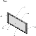
figure 4 is a perspective view of a set of one frame and one thermal insulation pad offigure 2 ; -
figure 5 is a view similar to that offigure 4 , in which the thermal insulation pad has been omitted; -
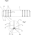
figure 6 is a longitudinal cross-section of the battery module offigure 1 , taken along the vertical plane Y-Z; -
figure 7 is a side view showing a detail of the battery module offigure 6 ; -
figure 8 is a longitudinal cross-section of the battery module offigure 1 , taken along the horizontal plane X-Y; -
figure 9 is a top view showing a detail of the battery module offigure 8 ; -
figure 10 is a top view showing another detail of the battery module offigure 8 ; -
figure 11 is a view similar to that offigure 6 , showing the evolution of the battery module over its life; and -
figure 12 is a view similar to that offigure 8 , showing the evolution of the battery module over its life. - Corresponding reference numerals refer to the same or corresponding parts in each of the figures. In
figures 1 and2 an orthonormal frame X-Y-Z is shown. In the following description, the vertical direction designates the direction parallel to the Z axis, and the horizontal direction designates any direction perpendicular to the vertical direction, in other words any direction contained in the X-Y plane. - With reference to
Figures 1 ,2 ,6 ,8 ,11 and12 , abattery module 2 comprises acage 4 and abattery cell array 6 held within saidcage 4. Thecage 4 comprises twoend plates 8 and twolateral plates 10 connecting theend plates 8 at both ends. Theend plates 8 and thelateral plates 10 are for example joined by welding. Thecage 4 typically has a rectangular box shape delimiting arectangular parallelepiped housing 12, theend plates 8 being shorter in length than thelateral plates 10. In other words, the twoend plates 8 extend in vertical planes substantially parallel to each other (and parallel to the plane X-Z inFigures 1 and2 ), and the twolateral plates 10 extend in vertical planes substantially parallel to each other (and parallel to the plane Y-Z inFigures 1 and2 ) and perpendicular to the extension planes of theend plates 8. - The
battery cell array 6 is arranged within thehousing 12 and comprisesseveral battery cells 14 stacked along a longitudinal direction A-A', severalthermal insulation pads 16, several frames 18. Preferably, thebattery cell array 6 further comprises twoelectrical insulation sheets 20. The longitudinal direction A-A' extends along the axis Y inFigures 1 and2 . Thebattery cells 14 are typically (but not limited to) prismatic battery cells. Thebattery cells 14 form a stack of battery cells, eachelectrical insulation sheet 20 being arranged at a respective end of the stack of battery cells. Thethermal insulation pads 16 and theframes 18 are inserted between thebattery cells 14 and separate thebattery cells 14 from each other in the longitudinal direction A-A'. In other words, each set formed of aframe 18 and athermal insulation pad 16 separates twobattery cells 14 from each other in the longitudinal direction A-A'. The number offrames 18 is therefore equal to the number ofthermal insulation pads 16, said number being for example equal to eleven in the particular embodiment shown inFigures 1 ,2 ,6 ,8 ,11 and12 . - The two
end plates 8 of thecage 4 enclose thebattery cell array 6 in the longitudinal direction A-A' (the twolateral plates 10 enclosing thebattery cell array 6 in the direction extending along the X axis inFigures 1 and2 ), eachend plate 8 covering a respectiveelectrical insulation sheet 20. Preferably, as shown inFigure 3 , the inner face (i.e. the face extending inside the battery module 2) of eachend plate 8 is provided with aninner recess 21. As shown inFigure 2 , eachinner recess 21 faces a correspondingend battery cell end battery cell electrical insulation sheet 20 arranged between theend plate 8 and theend battery cell inner recess 21 is an empty space of a concave shape, extending inwardly towards the outer face (i.e. towards the face extending outside the battery module 2) of thecorresponding end plate 8. Eachinner recess 21 has a vertical symmetry plane and a horizontal symmetry plane (said planes being not illustrated in the figures). The concave shape of eachinner recess 21 gradually changes its depth with the deepest peak at the centre of theinner recess 21, said centre being at the intersection of said vertical and horizontal symmetry planes. - Preferably, as shown in
Figure 3 , the inner face of eachend plate 8 is further provided with two side undercut rims 22. Each side undercutrim 22 extends along aninner side edge 24 of thecorresponding end plate 8, preferably along the entire length of theinner side edge 24 of saidend plate 8. For eachend plate 8, the two side undercut rims 22 extend on two opposite lateral sides of theend plate 8. As shown inFigure 9 , each side undercutrim 22 is configured to wrap the correspondingend battery cell battery cell - Each
battery cell 14 typically has a rectangular box shape whose main extension vertical plane is perpendicular to the longitudinal direction A-A' (and parallel to the X-Z plane inFigures 1 and2 ). The thickness of eachbattery cell 14 is measured in said longitudinal direction A-A'. - Each
thermal insulation pad 16 is arranged between twobattery cells 14 and is composed of a material deformable by compression (such a material deformable by compression being, for example, a composite sheet of woven glass fibre impregnated with perforated plastic). Eachthermal insulation pad 16 typically has a rectangular box shape whose main extension vertical plane is perpendicular to the longitudinal direction A-A' (and parallel to the X-Z plane inFigures 1 and2 ). The thickness of eachthermal insulation pad 16 is measured in the longitudinal direction A-A'. Eachthermal insulation pad 16 is for example a rectangular-shaped flexible plate. - Each
frame 18 is arranged between twobattery cells 14. As shown inFigure 5 , eachframe 18 is perforated with an opening 28 (typically a centralrectangular opening 28 which extends at the centre of said frame 18) which is configured to accommodate one of thethermal insulation pads 16. Eachframe 18 typically has a rectangular shape whose main extension vertical plane is perpendicular to the longitudinal direction A-A' (and parallel to the X-Z plane inFigures 1 and2 ). The thickness of eachframe 18 is measured in the longitudinal direction A-A'. Eachframe 18 is for example a rectangular-shaped plastic frame made from a plastic plate. As shown inFigure 4 , eachthermal insulation pad 16 is fitted into theopening 28 of one of the frames 18 (with the thickness of thethermal insulation pad 16 being preferably substantially equal to that of thecorresponding frame 18 into which it is fitted, as illustrated inFigures 4 and6 for example). According to a particular embodiment, the initial thickness of eachthermal insulation pad 16 is greater than the thickness of thecorresponding frame 18 into which it is fitted (which means that eachthermal insulation pad 16 is initially compressed by its twoadjacent battery cells 14 so as to have the final thickness of thepad 16 reach that the thickness of theframe 18, as described herein below). Indeed, eachthermal insulation pad 16 has some margin in its initial thickness (excessive thickness) for being compressed once positioned in thecage 4 with an initial compression force generated by thecage 4. - Preferably, as shown in
Figures 4 and5 , eachframe 18 is provided with a pair ofundercut rims edges undercut rims edges frame 18, as represented inFigures 4 and5 ). The two undercutrims opening 28 of thecorresponding frame 18 in the longitudinal direction A-A'. Preferably, each undercutrim corresponding edge frame 18. As shown inFigures 7 and10 , each undercutrim adjacent battery cell 14 at one of theedges 26 of saidbattery cell 14. Eachbattery cell 14 is thereby held by gripping by at least one (in the case of theend battery cells end battery cells end battery cell frame 18 on the one hand, and by the side undercut rims 22 of thecorresponding end plate 8 on the other hand. - The
electrical insulation sheets 20 aim to electrically insulate the battery cells enclosures (i.e. can and top cover of said enclosures) from the positive and negative poles of thebattery module 2, and thus avoiding corrosion and risks of short circuits within saidbattery module 2. Eachelectrical insulation sheet 20 is for example a rectangular-shaped plate made from an electrically insulating material. - A method for assembling the
battery module 2 according to the invention is herein described. - The method comprises a first step of providing the two
end plates 8 of thecage 4. The method further comprises a second step of stacking thebattery cells 14, the sets offrames 18 andthermal insulation pads 16, and the twoelectrical insulation sheets 20, along the longitudinal direction A-A'. Said stacking step is completed in such a way that each set, formed of aframe 18 and athermal insulation pad 16, separates twobattery cells 14 from each other in the longitudinal direction A-A', eachelectrical insulation sheet 20 being arranged at a respective end of the stack of battery cells, and the twoend plates 8 of thecage 4 enclosing thebattery cell array 6 in the longitudinal direction A-A'. Eachend plate 8 thus covers a respectiveelectrical insulation sheet 20, the side undercut rims 22 of theend plate 8 wrapping the correspondingend battery cell battery cell battery cells 14 and theframes 18 are in close contact at their edges (thebattery cells 14 being held by gripping by the undercut rims 30A, 30B of the frames 18). - In the above-mentioned embodiment wherein the initial thickness of each
thermal insulation pad 16 is greater than the thickness of thecorresponding frame 18 into which it is fitted, the stacking step comprises a phase of compressing eachthermal insulation pad 16 between the twoadjacent battery cells 14, separated by saidthermal insulation pad 16, by applying a longitudinal compression force onto the stack of battery cells along the longitudinal direction A-A'. Thebattery cells 14 thus get pushed to each other by the twoend plates 8 of thecage 4. A reactive compressive force is generated by thethermal insulation pads 16 onto thebattery cells 14, to apply initial compressive stress on those battery cells 14 (to be more precise, to the electrodes inside the battery cells cans) for proper contact between the battery cells electrodes, which is critical for a stable functioning of thebattery cells 14. - The method finally comprises a third step of providing the two
lateral plates 10 of thecage 4 and connecting saidlateral plates 10 at both ends of theend plates 8, for example by welding. In this way, the twolateral plates 10 enclose thebattery cell array 6 in a direction perpendicular to the longitudinal direction A-A' and parallel to the X-Y horizontal plane. - The operation of the
battery module 2 according to the invention will herein be described, with reference toFigures 11 and12 . During operation and over the course of their lifetime, eachbattery cell 14 tends to expand and swell, notably in the longitudinal direction A-A', due to thermal behaviour and gas release within thebattery cell 14. Consequently, as shown inFigures 11 and12 , thethermal insulation pads 16 are compressed within theirrespective openings 28 and accommodate the expansion of thebattery cells 14 in their compressed space, thereby resulting in a lower increase of tension on thelateral plates 10. Theinner recess 21 provided on the inner face of eachend plate 8 of thecage 4 works to accommodate the swelling expansions of theend battery cells end plate 8.
Claims (14)
- A battery module (2) comprising a cage (4) and a battery cell array (6) held within said cage (4), the battery cell array (6) comprising a plurality of battery cells (14, 14A, 14B) stacked along a longitudinal direction (A-A') and thereby forming a stack of battery cells, the cage (4) comprising two end plates (8) and two lateral plates (10) connecting said end plates (8) at both ends, the two end plates (8) enclosing the battery cell array (6) in the longitudinal direction (A-A'),
characterized in that at least one of the two end plates (8) is provided with an inner recess (21) on its inner face, said inner recess (21) facing the corresponding end battery cell (14A, 14B) and being configured to accommodate swelling of said end battery cell (14A, 14B). - The battery module (2) according to claim 1, wherein the battery cell array (6) further comprises a plurality of thermal insulation pads (16) and a plurality of frames (18), the thermal insulation pads (16) being inserted between the battery cells (14, 14A, 14B) and separating the battery cells (14, 14A, 14B) from each other in the longitudinal direction (A-A'), each thermal insulation pad (16) being composed of a material deformable by compression, the number of said frames (18) being equal to the number of thermal insulation pads (16), each frame (18) being arranged between two battery cells (14, 14A, 14B) and being perforated with an opening (28), said opening (28) being configured to accommodate one of the thermal insulation pads (16), each thermal insulation pad (16) being fitted into the opening (28) of one of the frames (18).
- The battery module (2) according to claim 2, wherein each thermal insulation pad (16) is a rectangular-shaped flexible plate.
- The battery module (2) according to claim 2 or 3, wherein the thickness of each thermal insulation pad (16) is greater than the thickness of the corresponding frame (18) into which it is fitted, the thickness being measured in the longitudinal direction (A-A').
- The battery module (2) according to any one of claims 2 to 4, wherein each frame (18) is provided with a pair of undercut rims (30A, 30B) on at least one of the edges (18A, 18B, 18C, 18D) of said frame (18), the two undercut rims (30A, 30B) extending on either side of the opening (28) of the frame (18) in the longitudinal direction (A-A'), each undercut rim (30A, 30B) being configured to grip a corresponding adjacent battery cell (14, 14A, 14B) at one of the edges (26) of said battery cell (14, 14A, 14B).
- The battery module (2) according to any one of claims 2 to 5, wherein the opening (28) is a rectangular-shaped opening which extends at the centre of the corresponding frame (18).
- The battery module (2) according to any one of claims 2 to 6, wherein each frame (18) is a rectangular-shaped plastic frame made from a plastic plate.
- The battery module (2) according to any one of the preceding claims, wherein at least one of the two end plates (8) is provided with at least one, preferably two, side undercut rim(s) (22) on its inner face, said at least one side undercut rim (22) extending along an inner side edge (24) of the end plate (8) and being configured to wrap the corresponding end battery cell (14A, 14B) at one of the side edges (26) of said end battery cell (14A, 14B).
- The battery module (2) according to any one of the preceding claims, wherein the battery cell array (6) further comprises two electrical insulation sheets (20) each arranged at a respective end of the stack of battery cells, each of said two end plates (8) covering a respective electrical insulation sheet (20).
- End plate (8) for a cage (4) of a battery module (2), said end plate (8) being intended to face an end battery cell (14A, 14B) of the battery module (2), characterized in that the end plate (8) is provided with an inner recess (21) on its inner face, said inner recess (21) being intended to face said end battery cell (14A, 14B) and being configured to accommodate swelling of said end battery cell (14A, 14B).
- End plate (8) according to claim 10, wherein said inner recess (21) has concave shape and extends inwardly towards the outer face of the end plate (8).
- Method for assembling a battery module (2) according to any one of claims 1 to 9, characterized in that the method comprises the steps of:- providing the two end plates (8) of the cage (4);- stacking, along the longitudinal direction (A-A'), the plurality of battery cells (14, 14A, 14B), in such a way that the two end plates (8) of the cage (4) enclose the battery cell array (6) in the longitudinal direction (A-A');- providing the two lateral plates (10) of the cage (4) and connecting said lateral plates (10) at both ends of the end plates (8).
- Method according to claim 12 when the battery module (2) is according to claim 2, wherein the stacking step further comprises stacking the plurality of sets of frames (18) and thermal insulation pads (16), in such a way that each set, formed of a frame (18) and a thermal insulation pad (16), separates two battery cells (14, 14A, 14B) from each other in the longitudinal direction (A-A').
- Method according to claim 13, wherein the stacking step comprises a phase of compressing each thermal insulation pad (16) between the two adjacent battery cells (14, 14A, 14B) separated by said thermal insulation pad (16), by applying a longitudinal compression force onto the stack of battery cells along the longitudinal direction (A-A').
Priority Applications (1)
| Application Number | Priority Date | Filing Date | Title |
|---|---|---|---|
| EP22307067.3A EP4395027A1 (en) | 2022-12-30 | 2022-12-30 | Battery module and method for assembling such a battery module |
Applications Claiming Priority (1)
| Application Number | Priority Date | Filing Date | Title |
|---|---|---|---|
| EP22307067.3A EP4395027A1 (en) | 2022-12-30 | 2022-12-30 | Battery module and method for assembling such a battery module |
Publications (1)
| Publication Number | Publication Date |
|---|---|
| EP4395027A1 true EP4395027A1 (en) | 2024-07-03 |
Family
ID=85511115
Family Applications (1)
| Application Number | Title | Priority Date | Filing Date |
|---|---|---|---|
| EP22307067.3A Pending EP4395027A1 (en) | 2022-12-30 | 2022-12-30 | Battery module and method for assembling such a battery module |
Country Status (1)
| Country | Link |
|---|---|
| EP (1) | EP4395027A1 (en) |
Citations (4)
| Publication number | Priority date | Publication date | Assignee | Title |
|---|---|---|---|---|
| EP3131137A1 (en) * | 2014-04-11 | 2017-02-15 | Panasonic Intellectual Property Management Co., Ltd. | Battery pack |
| WO2019021778A1 (en) * | 2017-07-27 | 2019-01-31 | 三洋電機株式会社 | Battery module, and vehicle equipped with same |
| US20220131118A1 (en) * | 2020-10-27 | 2022-04-28 | Ford Global Technologies, Llc | Traction battery cell expansion accommodating endplate and expansion accommodating method |
| CN217719815U (en) * | 2022-07-28 | 2022-11-01 | 宁德时代新能源科技股份有限公司 | Battery modules, batteries and electrical devices |
-
2022
- 2022-12-30 EP EP22307067.3A patent/EP4395027A1/en active Pending
Patent Citations (4)
| Publication number | Priority date | Publication date | Assignee | Title |
|---|---|---|---|---|
| EP3131137A1 (en) * | 2014-04-11 | 2017-02-15 | Panasonic Intellectual Property Management Co., Ltd. | Battery pack |
| WO2019021778A1 (en) * | 2017-07-27 | 2019-01-31 | 三洋電機株式会社 | Battery module, and vehicle equipped with same |
| US20220131118A1 (en) * | 2020-10-27 | 2022-04-28 | Ford Global Technologies, Llc | Traction battery cell expansion accommodating endplate and expansion accommodating method |
| CN217719815U (en) * | 2022-07-28 | 2022-11-01 | 宁德时代新能源科技股份有限公司 | Battery modules, batteries and electrical devices |
Similar Documents
| Publication | Publication Date | Title |
|---|---|---|
| US20240021860A1 (en) | Pack case, battery pack, and method for manufacturing pack case | |
| EP3890085B1 (en) | Battery cell assembly, battery module and battery pack | |
| US6899975B2 (en) | Battery pack | |
| US20170194676A1 (en) | Power source device | |
| KR102851920B1 (en) | Battery pack and vehicle including the same | |
| US20200136108A1 (en) | Energy storage apparatus | |
| JP4700783B2 (en) | Manufacturing method of assembled battery and design method of binding force in assembled battery | |
| US12244034B2 (en) | Buffer member and electrical storage module | |
| JP6463471B2 (en) | Battery case, battery module, and battery module manufacturing method | |
| US20200212412A1 (en) | Battery module and battery pack | |
| JP7567874B2 (en) | Power storage device | |
| JP2019075276A (en) | Battery pack | |
| KR102432538B1 (en) | Battery module and manufacturing method thereof | |
| JP2021089788A (en) | Battery pack | |
| CN115298886B (en) | Battery assembly | |
| JP7241291B2 (en) | Battery modules and battery packs | |
| JP7147535B2 (en) | battery pack | |
| JP7261911B2 (en) | storage cell | |
| JP6031388B2 (en) | Assembled battery | |
| KR20250081783A (en) | Battery module | |
| KR100649211B1 (en) | Secondary battery module | |
| WO2020059299A1 (en) | Battery module | |
| JPH10188927A (en) | Assembly battery structure | |
| KR102955144B1 (en) | Battery module | |
| EP3675202B1 (en) | Secondary battery and battery module |
Legal Events
| Date | Code | Title | Description |
|---|---|---|---|
| PUAI | Public reference made under article 153(3) epc to a published international application that has entered the european phase |
Free format text: ORIGINAL CODE: 0009012 |
|
| STAA | Information on the status of an ep patent application or granted ep patent |
Free format text: STATUS: THE APPLICATION HAS BEEN PUBLISHED |
|
| AK | Designated contracting states |
Kind code of ref document: A1 Designated state(s): AL AT BE BG CH CY CZ DE DK EE ES FI FR GB GR HR HU IE IS IT LI LT LU LV MC ME MK MT NL NO PL PT RO RS SE SI SK SM TR |
|
| STAA | Information on the status of an ep patent application or granted ep patent |
Free format text: STATUS: REQUEST FOR EXAMINATION WAS MADE |
|
| 17P | Request for examination filed |
Effective date: 20241223 |