EP4395024A1 - Top cover for battery, and battery - Google Patents
Top cover for battery, and battery Download PDFInfo
- Publication number
- EP4395024A1 EP4395024A1 EP22874928.9A EP22874928A EP4395024A1 EP 4395024 A1 EP4395024 A1 EP 4395024A1 EP 22874928 A EP22874928 A EP 22874928A EP 4395024 A1 EP4395024 A1 EP 4395024A1
- Authority
- EP
- European Patent Office
- Prior art keywords
- pole
- battery
- sub
- top cover
- bodies
- Prior art date
- Legal status (The legal status is an assumption and is not a legal conclusion. Google has not performed a legal analysis and makes no representation as to the accuracy of the status listed.)
- Pending
Links
Images

Classifications
-
- H—ELECTRICITY
- H01—ELECTRIC ELEMENTS
- H01M—PROCESSES OR MEANS, e.g. BATTERIES, FOR THE DIRECT CONVERSION OF CHEMICAL ENERGY INTO ELECTRICAL ENERGY
- H01M50/00—Constructional details or processes of manufacture of the non-active parts of electrochemical cells other than fuel cells, e.g. hybrid cells
- H01M50/10—Primary casings; Jackets or wrappings
- H01M50/172—Arrangements of electric connectors penetrating the casing
- H01M50/174—Arrangements of electric connectors penetrating the casing adapted for the shape of the cells
- H01M50/176—Arrangements of electric connectors penetrating the casing adapted for the shape of the cells for prismatic or rectangular cells
-
- H—ELECTRICITY
- H01—ELECTRIC ELEMENTS
- H01M—PROCESSES OR MEANS, e.g. BATTERIES, FOR THE DIRECT CONVERSION OF CHEMICAL ENERGY INTO ELECTRICAL ENERGY
- H01M50/00—Constructional details or processes of manufacture of the non-active parts of electrochemical cells other than fuel cells, e.g. hybrid cells
- H01M50/50—Current conducting connections for cells or batteries
- H01M50/543—Terminals
- H01M50/564—Terminals characterised by their manufacturing process
- H01M50/567—Terminals characterised by their manufacturing process by fixing means, e.g. screws, rivets or bolts
-
- H—ELECTRICITY
- H01—ELECTRIC ELEMENTS
- H01M—PROCESSES OR MEANS, e.g. BATTERIES, FOR THE DIRECT CONVERSION OF CHEMICAL ENERGY INTO ELECTRICAL ENERGY
- H01M50/00—Constructional details or processes of manufacture of the non-active parts of electrochemical cells other than fuel cells, e.g. hybrid cells
- H01M50/10—Primary casings; Jackets or wrappings
- H01M50/147—Lids or covers
-
- H—ELECTRICITY
- H01—ELECTRIC ELEMENTS
- H01M—PROCESSES OR MEANS, e.g. BATTERIES, FOR THE DIRECT CONVERSION OF CHEMICAL ENERGY INTO ELECTRICAL ENERGY
- H01M50/00—Constructional details or processes of manufacture of the non-active parts of electrochemical cells other than fuel cells, e.g. hybrid cells
- H01M50/10—Primary casings; Jackets or wrappings
- H01M50/147—Lids or covers
- H01M50/148—Lids or covers characterised by their shape
- H01M50/15—Lids or covers characterised by their shape for prismatic or rectangular cells
-
- H—ELECTRICITY
- H01—ELECTRIC ELEMENTS
- H01M—PROCESSES OR MEANS, e.g. BATTERIES, FOR THE DIRECT CONVERSION OF CHEMICAL ENERGY INTO ELECTRICAL ENERGY
- H01M50/00—Constructional details or processes of manufacture of the non-active parts of electrochemical cells other than fuel cells, e.g. hybrid cells
- H01M50/30—Arrangements for facilitating escape of gases
- H01M50/342—Non-re-sealable arrangements
- H01M50/3425—Non-re-sealable arrangements in the form of rupturable membranes or weakened parts, e.g. pierced with the aid of a sharp member
-
- H—ELECTRICITY
- H01—ELECTRIC ELEMENTS
- H01M—PROCESSES OR MEANS, e.g. BATTERIES, FOR THE DIRECT CONVERSION OF CHEMICAL ENERGY INTO ELECTRICAL ENERGY
- H01M50/00—Constructional details or processes of manufacture of the non-active parts of electrochemical cells other than fuel cells, e.g. hybrid cells
- H01M50/50—Current conducting connections for cells or batteries
- H01M50/543—Terminals
- H01M50/547—Terminals characterised by the disposition of the terminals on the cells
- H01M50/55—Terminals characterised by the disposition of the terminals on the cells on the same side of the cell
-
- H—ELECTRICITY
- H01—ELECTRIC ELEMENTS
- H01M—PROCESSES OR MEANS, e.g. BATTERIES, FOR THE DIRECT CONVERSION OF CHEMICAL ENERGY INTO ELECTRICAL ENERGY
- H01M50/00—Constructional details or processes of manufacture of the non-active parts of electrochemical cells other than fuel cells, e.g. hybrid cells
- H01M50/50—Current conducting connections for cells or batteries
- H01M50/543—Terminals
- H01M50/552—Terminals characterised by their shape
- H01M50/553—Terminals adapted for prismatic, pouch or rectangular cells
-
- Y—GENERAL TAGGING OF NEW TECHNOLOGICAL DEVELOPMENTS; GENERAL TAGGING OF CROSS-SECTIONAL TECHNOLOGIES SPANNING OVER SEVERAL SECTIONS OF THE IPC; TECHNICAL SUBJECTS COVERED BY FORMER USPC CROSS-REFERENCE ART COLLECTIONS [XRACs] AND DIGESTS
- Y02—TECHNOLOGIES OR APPLICATIONS FOR MITIGATION OR ADAPTATION AGAINST CLIMATE CHANGE
- Y02E—REDUCTION OF GREENHOUSE GAS [GHG] EMISSIONS, RELATED TO ENERGY GENERATION, TRANSMISSION OR DISTRIBUTION
- Y02E60/00—Enabling technologies; Technologies with a potential or indirect contribution to GHG emissions mitigation
- Y02E60/10—Energy storage using batteries
Definitions
- the disclosure relates to the technical field of batteries, and particularly relates to a top cover for a battery and a battery having the top cover for a battery.
- a top cover for a battery is connected to an aluminum housing of the battery, so an internal structure of the battery is separated from the outside.
- the top cover for a battery is used to electrically connect an interior of the battery to the outside.
- the top cover for a battery can transmit an electric current in the battery to the outside. That is, the top cover for a battery can play a role of guiding an electric current.
- an objective of the disclosure is to provide a top cover for a battery.
- the top cover for a battery is provided with a plurality of pole bodies such that an overcurrent capability of a cell and working performance of the battery can be improved.
- the plurality of pole bodies may be connected to the same pole riveting block such that the overcurrent capability of the cell and the working performance of the battery can be improved.
- the disclosure further provides a battery using the above top cover for a battery.
- the pole body 30 may be connected to the pole riveting block 20 through riveting, and then laser welding may be carried out along a riveting edge such that internal resistance of connection between the pole body 30 and the pole riveting block 20 can be reduced.
- an internal space of a housing of the battery occupied by the pole bodies 30 can be reduced such that an available space in the housing of the battery, an arrangement space of the cell in the housing, and energy density of the battery can be increased.
- the mounting grooves 12 are provided on the body 10, weight of the body 10 is reduced, which facilitates a lightweight design of the battery.
- the top cover 100 may further include an explosion-proof valve 40.
- the explosion-proof valve 40 may be arranged on the body 10.
- a protective film may be arranged on the explosion-proof valve 40.
- the explosion-proof valve 40 can quickly carry out ventilation, pressure relief and explosion proofing, such that the problem of self-explosion of the battery is solved to a certain extent.
- a plurality of vent holes 16 may be provided at positions of the lower plastic 15 opposite the explosion-proof valve 40. In this way, when thermal runaway occurs on the battery, the explosion-proof valve 40 can quickly carry out ventilation and pressure relief.
- a plurality of weight-reducing grooves 17 may be provided on the lower plastic 15.
- weight of the top cover 100 can be reduced such that a lightweight design of the battery is facilitated.
- materials are saved such that cost is reduced.
- H3 and H1 may satisfy a relational expression as follows: 0.5 ⁇ H3/H1 ⁇ 0.8. That is, a ratio of H3 to H1 may be any numerical value between 0.5 and 0.8. In this way, a ratio of the width of the first sub-pole body 31 and the width of the second sub-pole body 32 to the width of the body 10 may be reasonable such that usage safety of the battery can be ensured on the basis that an overcurrent capability of a cell is improved.
- the plurality of pole bodies 30 are all located on one side of the explosion-proof valve 40 in the left-right direction shown in FIG. 1 .
- the plurality of pole bodies 30 are all located on a left side of the explosion-proof valve 40, such that arrangement positions of the plurality of pole bodies 30 and the explosion-proof valve 40 can be reasonable, and usage reliability of the top cover 100 can be ensured.
- the battery according to an example of the disclosure includes the top cover 100 of the battery in the above example.
- a total volume of the pole bodies 30 and a sum of cross-sectional areas of the pole bodies 30 can be increased. Therefore, an overcurrent capability of a cell and working performance of the battery can be improved.
- the plurality of pole bodies 30 can be connected to the same pole riveting block 20 such that a cross-sectional area of the pole riveting block 20 can be increased. Therefore, the overcurrent capability of the cell and the working performance of the battery can be improved.
- the description with reference to the terms “an example”, “some examples”, “examples”, “instances”, “particular instances”, or “some instances”, etc. means that a specific feature, structure, material or characteristic described in combination with the example or instance is included in at least one example or instance of the disclosure. In the description, schematic expressions of the above terms do not certainly refer to the same example or instance. Moreover, the specific feature, structure, material or characteristic described can be combined in a suitable manner in any one or more examples or instances.
Landscapes
- Chemical & Material Sciences (AREA)
- Chemical Kinetics & Catalysis (AREA)
- Electrochemistry (AREA)
- General Chemical & Material Sciences (AREA)
- Engineering & Computer Science (AREA)
- Manufacturing & Machinery (AREA)
- Connection Of Batteries Or Terminals (AREA)
Abstract
Description
- The disclosure claims the benefit of priority to
Chinese Patent Application No. 202122384222.6, filed on September 29, 2021 - The disclosure relates to the technical field of batteries, and particularly relates to a top cover for a battery and a battery having the top cover for a battery.
- In the related art, a top cover for a battery is connected to an aluminum housing of the battery, so an internal structure of the battery is separated from the outside. The top cover for a battery is used to electrically connect an interior of the battery to the outside. Moreover, the top cover for a battery can transmit an electric current in the battery to the outside. That is, the top cover for a battery can play a role of guiding an electric current.
- Only one pole is arranged at the top cover for a battery. If a cell has a small thickness (for example, less than 20 mm), the pole will have a small size, and an area of connection between the pole and the interior of the battery will be too small (for example, an area of welding between the pole and a tab will be too small). Therefore, the cell will have a weak overcurrent capability, so as to affect working performance of the battery.
- The disclosure aims to solve at least one of the technical problems in the prior art. Therefore, an objective of the disclosure is to provide a top cover for a battery. The top cover for a battery is provided with a plurality of pole bodies such that an overcurrent capability of a cell and working performance of the battery can be improved. Moreover, the plurality of pole bodies may be connected to the same pole riveting block such that the overcurrent capability of the cell and the working performance of the battery can be improved.
- The disclosure further provides a battery using the above top cover for a battery.
- A top cover for a battery according to Example 1 of the disclosure includes a body; and a pole riveting block and a plurality of pole bodies. The plurality of pole bodies are arranged on the body and connected to the pole riveting block.
- The battery according to the disclosure includes the above top cover for a battery.
- Some additional aspects and advantages of the disclosure will be provided in the following descriptions and some will become obvious in the following descriptions or can be known by practice of the disclosure.
-
-
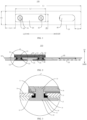
FIG. 1 is a top view of a top cover according to an example of the disclosure; -
FIG. 2 is a sectional view of a top cover according to an example of the disclosure; -
FIG. 3 is an enlarged view of position A inFIG. 2 ; -
FIG. 4 is a bottom view of a top cover according to an example of the disclosure; -
FIG. 5 is a schematic diagram of a top cover according to an example of the disclosure; and -
FIG. 6 is a schematic diagram from another angle of a top cover according to the example of the disclosure. - Reference numerals in the description are as follows:
-
top cover 100, -
body 10,mounting hole 11,mounting groove 12,upper plastic 13,seal member 14,lower plastic 15,vent hole 16, weight-reducinggroove 17,positive mark 18, -
pole riveting block 20, -
pole body 30,first sub-pole body 31,second sub-pole body 32,first sub-pole 33,second sub-pole 34, and - explosion-
proof valve 40. - Examples of the disclosure will be described in detail below. Instances of the examples are shown in accompanying drawings, throughout which identical or similar reference numerals denote identical or similar elements or elements having identical or similar functions. Examples described with reference to accompanying drawings are illustrative and merely used for explaining the disclosure, instead of being construed as a limitation on the disclosure.
- The disclosure will be described in detail below with reference to accompanying drawings and in combination with examples.
- As shown in
FIG. 1-FIG. 6 , atop cover 100 for a battery according to an example of the disclosure includes abody 10, a pole rivetingblock 20 and a plurality ofpole bodies 30. In some examples, the plurality ofpole bodies 30 are arranged on thebody 10, and the plurality ofpole bodies 30 are connected to the pole rivetingblock 20. - In some examples, the battery may be a blade battery. The
top cover 100 may be welded to an aluminum housing of the battery such that an internal structure of the battery is separated from the outside. Moreover, an end of thepole body 30 away from the pole rivetingblock 20 may be electrically connected to a tab of the battery, and the pole rivetingblock 20 may be electrically connected to an external structure of the battery. Thetop cover 100 can play a role of guiding an electric current, and thetop cover 100 can transmit an electric current in the battery to the outside. - Optionally, the
pole body 30 may be connected to the pole rivetingblock 20 through riveting, and then laser welding may be carried out along a riveting edge such that internal resistance of connection between thepole body 30 and the pole rivetingblock 20 can be reduced. - Optionally, the
body 10 may be constructed as a bare aluminum sheet, and the plurality ofpole bodies 30 have the same polarity. For instance, the plurality ofpole bodies 30 are allpositive pole bodies 30, or the plurality ofpole bodies 30 are allnegative pole bodies 30. - In the prior art, only one pole is arranged at the top cover for a battery. If a cell has a small thickness (for instance, less than 20 mm), the pole will have a small size, and an area of connection between the pole and the interior of the battery will be too small (for instance, an area of welding between the pole and a tab will be too small). Therefore, the cell will have a weak overcurrent capability, so as to affect working performance of the battery.
- In the disclosure, by arranging a plurality of
pole bodies 30 on thebody 10, a total volume of thepole bodies 30 and a sum of cross-sectional areas of thepole bodies 30 can be increased such that an area of connection between thepole bodies 30 and the interior of the battery can be increased (for instance, an area of welding between thepole bodies 30 and a tab can be increased). Therefore, an overcurrent capability of the cell and working performance of the battery can be improved. - Moreover, the plurality of
pole bodies 30 may be connected to the same pole rivetingblock 20, or it can be understood that the pole rivetingblock 20 is an integrated structure. In this way, a cross-sectional area of the pole rivetingblock 20 and an area of electrical connection between the pole rivetingblock 20 and the external structure of the battery can be increased. Therefore, the overcurrent capability of the cell is improved and the battery is ensured to have excellent charge and discharge performance. - Thus, a total volume of the
pole bodies 30 and a sum of cross-sectional areas of thepole bodies 30 can be increased by arranging a plurality ofpole bodies 30. Therefore, an overcurrent capability of the cell and working performance of the battery can be improved. Moreover, the plurality ofpole bodies 30 may be connected to the same pole rivetingblock 20 such that a cross-sectional area of the pole rivetingblock 20 can be increased. Therefore, the overcurrent capability of the cell and the working performance of the battery can be improved. - Optionally, as shown in
FIG. 2 and FIG. 3 , a plurality ofmounting grooves 12 may be provided on thebody 10. A number of themounting grooves 12 may be the same as a number of thepole bodies 30. The plurality ofmounting grooves 12 may correspond to the plurality ofpole bodies 30 in a one-to-one manner. Themounting grooves 12 may be provided on an inner surface of thebody 10 opposite an interior of the battery. Moreover, the mountinggrooves 12 may be recessed towards the interior of thebody 10. At least part of thepole body 30 may be arranged in the mountinggroove 12 corresponding thereto. In this way, an internal space of a housing of the battery occupied by thepole bodies 30 can be reduced such that an available space in the housing of the battery, an arrangement space of the cell in the housing, and energy density of the battery can be increased. Moreover, since the mountinggrooves 12 are provided on thebody 10, weight of thebody 10 is reduced, which facilitates a lightweight design of the battery. - In some examples of the disclosure, as shown in
FIG. 2 and FIG. 3 , a plurality of mountingholes 11 may be provided on thebody 10. Optionally, a number of the mountingholes 11 may be the same as a number of thepole bodies 30. The mounting holes 11 may correspond to the mountinggrooves 12 in a one-to-one manner. The plurality ofpole bodies 30 may be mounted in the mounting holes 11. Moreover, at least part of thepole body 30 may pass through the mountinghole 11 corresponding thereto, so as to be connected to the poleriveting block 20. In this way, a volume of thetop cover 100 can be reduced such that the available space in the housing of the battery can be increased, which can improve the energy density of the battery. - In some examples of the disclosure, as shown in
FIG. 1-FIG. 6 , the plurality ofpole bodies 30 may include firstsub-pole bodies 31 and secondsub-pole bodies 32. In some examples, the firstsub-pole bodies 31 and the secondsub-pole bodies 32 may be spaced apart from each other in a length direction of the body 10 (that is, in a left-right direction shown inFIG. 1 ). In this way, arrangement positions of the firstsub-pole bodies 31 and the secondsub-pole bodies 32 can be reasonable, and interference between the firstsub-pole bodies 31 and the secondsub-pole bodies 32 can be avoided. - Optionally, as shown in
FIG. 2 and FIG. 3 , the firstsub-pole body 31 and the secondsub-pole body 32 may each include a first sub-pole 33 and asecond sub-pole 34. The first sub-pole 33 and the second sub-pole 34 may be configured as an integrally formed member. At least part of the second sub-pole 34 may be arranged in the mountinggroove 12. The first sub-pole 33 may pass through the mountinghole 11 to be connected to the poleriveting block 20. - Optionally, as shown in
FIG. 2 and FIG. 3 ,lower plastic 15 may be arranged between the second sub-pole 34 and thebody 10. Insulation and protection may be carried out between the second sub-pole 34 and thebody 10 by means of thelower plastic 15. Upper plastic 13 may be arranged between the poleriveting block 20 and thebody 10. Insulation and protection may be carried out between the poleriveting block 20 and thebody 10 by means of theupper plastic 13. Aseal member 14 may be arranged between the first sub-pole 33 and the mountinghole 11. In some examples, theseal member 14 may be configured as a rubber ring. A position of contact between the first sub-pole 33 and the mountinghole 11 may be sealed by means of the rubber ring. In this way, working reliability and usage safety of thetop cover 100 can be ensured. - In some examples of the disclosure, as shown in
FIG. 1 , a length of thebody 10 may be L1, a length of the poleriveting block 20 may be L2, and the length of thebody 10 and the length of the poleriveting block 20 may satisfy a relational expression as follows: 0.3≤L2/L1≤0.5. That is, a ratio of the length of the poleriveting block 20 to the length of thebody 10 may be any numerical value between 0.3 and 0.5. For instance, if the length of thebody 10 is 90 mm, the length of the poleriveting block 20 may be any numerical value between 27 mm and 45 mm. For instance, the length of the poleriveting block 20 may be 36 mm. In this way, the ratio of the length of the poleriveting block 20 to the length of thebody 10 may be reasonable such that usage safety of the battery can be ensured on the basis that an overcurrent capability of a cell is improved. - In some examples of the disclosure, as shown in
FIG. 1, FIG. 2 andFIG. 5 , thetop cover 100 may further include an explosion-proof valve 40. The explosion-proof valve 40 may be arranged on thebody 10. A protective film may be arranged on the explosion-proof valve 40. In some examples, when thermal runaway occurs on the battery, the explosion-proof valve 40 can quickly carry out ventilation, pressure relief and explosion proofing, such that the problem of self-explosion of the battery is solved to a certain extent. - Optionally, as shown in
FIG. 2 andFIG. 4 , in a thickness direction (that is, an up-down direction shown inFIG. 2 ) of thetop cover 100, a plurality of vent holes 16 may be provided at positions of thelower plastic 15 opposite the explosion-proof valve 40. In this way, when thermal runaway occurs on the battery, the explosion-proof valve 40 can quickly carry out ventilation and pressure relief. - Optionally, as shown in
FIG. 6 , a plurality of weight-reducinggrooves 17 may be provided on thelower plastic 15. In this way, weight of thetop cover 100 can be reduced such that a lightweight design of the battery is facilitated. Moreover, materials are saved such that cost is reduced. - In some examples, the
body 10 has a first end and a second end that are opposite each other in a length direction (that is, a left-right direction as shown inFIG. 1 ) of thebody 10. In some examples, a left end of thebody 10 may be the first end of thebody 10, and a right end of thebody 10 may be the second end of thebody 10. - As shown in
FIG. 1 , a distance between an end of the poleriveting block 20 away from the explosion-proof valve 40 and the first end may be L3, a length of thebody 10 may be L1, and L3 and L1 may satisfy a relational expression as follows: 0.1≤L3/L1≤0.3. That is, a ratio of L3 to L1 may be any numerical value between 0.1 and 0.3. For instance, if the length of thebody 10 is 90 mm, a distance between an end of the poleriveting block 20 away from the explosion-proof valve 40 and the first end may be any numerical value between 9 mm and 27 mm. - In some other examples, as shown in
FIG. 1 , a distance between an end of the explosion-proof valve 40 away from the poleriveting block 20 and the second end may be L4, and L4 and L1 may satisfy a relational expression as follows: 0.05≤L4/L1≤0.3. That is, a ratio of L4 to L1 may be any numerical value between 0.05 and 0.3. For instance, if the length of thebody 10 is 90 mm, the distance between an end of the explosion-proof valve 40 away from the poleriveting block 20 and the second end may be any numerical value between 4.5 mm and 27 mm. In this way, a ratio of L3 to L1 may be reasonable, and a ratio of L4 to L1 is reasonable. Therefore, arrangement positions of the poleriveting block 20 and the explosion-proof valve 40 can be reasonable, and usage reliability of the battery can be ensured. - In some examples of the disclosure, as shown in
FIG. 1 , a width of thebody 10 may be H1, a width of the poleriveting block 20 may be H2, and the width of thebody 10 and the width of the poleriveting block 20 may satisfy a relational expression as follows: 0.5≤H2/H1≤0.9. That is, a ratio of the width of the poleriveting block 20 to the width of thebody 10 may be any numerical value between 0.5 and 0.9. In this way, the ratio of the width of the poleriveting block 20 to the width of thebody 10 may be reasonable such that usage safety of the battery can be ensured on the basis that an overcurrent capability of a cell is improved. - In some examples of the disclosure, as shown in
FIG. 1 andFIG. 4 , a length of the firstsub-pole body 31 may be L5, and a length of the secondsub-pole body 32 may be L6. In some examples, a length of thesecond sub-pole 34 of the firstsub-pole body 31 may be L5, a length of thesecond sub-pole 34 of the secondsub-pole body 32 may be L6, a length of the poleriveting block 20 may be L2, and L5, L6, and L2 may satisfy a relational expression as follows: 0.5≤(L5+L6)/L2≤1.5. Optionally, the length of thesecond sub-pole 34 of the firstsub-pole body 31 may be the same as the length of thesecond sub-pole 34 of the second sub-pole body 32 (that is, L5 may be equal to L6), or the length of thesecond sub-pole 34 of the firstsub-pole body 31 may be different from the length of thesecond sub-pole 34 of the second sub-pole body 32 (that is, L5 may not be equal to L6). In this way, a numerical relation between L5, L6 and L2 may be reasonable, such that the battery is ensured to have excellent charge and discharge performance. - In some examples of the disclosure, as shown in
FIG. 4 , the width of the firstsub-pole body 31 may be H3, the width of the secondsub-pole body 32 may be H3, or the width of the firstsub-pole body 31 and the width of the secondsub-pole body 32 may be H3. In some examples, the width of the firstsub-pole body 31 and the width of the secondsub-pole body 32 may be H3. In some examples, the width of thesecond sub-pole 34 of the firstsub-pole body 31 may be H3, and the width of thesecond sub-pole 34 of the secondsub-pole body 32 may be H3. - Furthermore, H3 and H1 may satisfy a relational expression as follows: 0.5≤H3/H1≤0.8. That is, a ratio of H3 to H1 may be any numerical value between 0.5 and 0.8. In this way, a ratio of the width of the first
sub-pole body 31 and the width of the secondsub-pole body 32 to the width of thebody 10 may be reasonable such that usage safety of the battery can be ensured on the basis that an overcurrent capability of a cell is improved. - As some examples of the disclosure, an end of the first
sub-pole body 31 and an end of the secondsub-pole body 32 which are away from the poleriveting block 20 may be of a separate structure. That is, the firstsub-pole body 31 and the secondsub-pole body 32 are directly welded to a tab of the battery. In this way, it is not required to connect the firstsub-pole body 31 and the secondsub-pole body 32 together and then weld same to the tab of the battery such that assembly difficulty of the battery can be reduced, and assembly efficiency of the battery can be increased. - As some examples of the disclosure, as shown in
FIG. 5 , apositive mark 18 or a negative mark may be arranged on thebody 10. Optionally, thepositive mark 18 may be configured as a cross-shaped groove, and the negative mark may be configured as a rectangular groove. By arranging thepositive mark 18 or the negative mark on thebody 10, it is convenient for an operator to distinguish positive and negative polarities of thepole body 30 on thetop cover 100, so as to facilitate assembly of the battery pack. - As some examples of the disclosure, as shown in
FIG. 1 , the plurality ofpole bodies 30 are all located on one side of the explosion-proof valve 40 in the left-right direction shown inFIG. 1 . For instance, in an instance shown inFIG. 1 , the plurality ofpole bodies 30 are all located on a left side of the explosion-proof valve 40, such that arrangement positions of the plurality ofpole bodies 30 and the explosion-proof valve 40 can be reasonable, and usage reliability of thetop cover 100 can be ensured. - The battery according to an example of the disclosure includes the
top cover 100 of the battery in the above example. By arranging a plurality ofpole bodies 30, a total volume of thepole bodies 30 and a sum of cross-sectional areas of thepole bodies 30 can be increased. Therefore, an overcurrent capability of a cell and working performance of the battery can be improved. Moreover, the plurality ofpole bodies 30 can be connected to the same poleriveting block 20 such that a cross-sectional area of the poleriveting block 20 can be increased. Therefore, the overcurrent capability of the cell and the working performance of the battery can be improved. - In the description, the description with reference to the terms "an example", "some examples", "examples", "instances", "particular instances", or "some instances", etc. means that a specific feature, structure, material or characteristic described in combination with the example or instance is included in at least one example or instance of the disclosure. In the description, schematic expressions of the above terms do not certainly refer to the same example or instance. Moreover, the specific feature, structure, material or characteristic described can be combined in a suitable manner in any one or more examples or instances.
- Although examples of the disclosure are shown and described, those of ordinary skill in the art can understand that various changes, modifications, replacements and variations can be made to these examples without departing from the principles and purposes of the disclosure, and the scope of the disclosure is limited by the claims and their equivalents.
Claims (10)
- A top cover for a battery, comprising:a body; anda pole riveting block and a plurality of pole bodies, wherein the plurality of pole bodies are arranged on the body, and the plurality of pole bodies are connected to the pole riveting block.
- The top cover for a battery according to claim 1, wherein the body is provided with a plurality of mounting holes, the plurality of pole bodies are mounted in the mounting holes, and the pole bodies pass through the mounting holes corresponding to the pole bodies so as to be electrically connected to the pole riveting block.
- The top cover for a battery according to claim 1, wherein the plurality of pole bodies comprise first sub-pole bodies and second sub-pole bodies, the first sub-pole bodies and the second sub-pole bodies are spaced apart from each other in a length direction of the body.
- The top cover for a battery according to claim 1, wherein a length of the body is L1, a length of the pole riveting block is L2, and a following relational expression is satisfied: 0.3≤L2/L1≤0.5.
- The top cover for a battery according to claims 1-4, further comprising an explosion-proof valve, wherein the explosion-proof valve is arranged on the body, the body has a first end and a second end that are opposite each other in the length direction of the body, a distance between an end of the pole riveting block away from the explosion-proof valve and the first end is L3, the length of the body is L1, and a following relational expression is satisfied: 0.1≤L3/L1≤0.3.
- The top cover for a battery according to claim 5, wherein a distance between the end of the explosion-proof valve away from the pole riveting block and the second end is L4, and a following relational expression is satisfied: 0.05≤L4/L1≤0.3.
- The top cover for a battery according to claims 1-6, wherein a width of the body is H1, a width of the pole riveting block is H2, and a following relational expression is satisfied: 0.5≤H2/H1≤0.9.
- The top cover for a battery according to claim 3, wherein a length of the first sub-pole body is L5, a length of the second sub-pole body is L6, a length of the pole riveting block is L2, and a following relational expression is satisfied: 0.5≤(L5+L6)/L2≤1.5.
- The top cover for a battery according to claim 7, wherein a width of the first sub-pole body is H3, a width of the second sub-pole body is H3, and a following relational expression is satisfied: 0.5≤H3/H1≤0.8.
- A battery, comprising the top cover for a battery according to any one of claims 1-9.
Applications Claiming Priority (2)
| Application Number | Priority Date | Filing Date | Title |
|---|---|---|---|
| CN202122384222.6U CN215911486U (en) | 2021-09-29 | 2021-09-29 | Top cover of battery and battery |
| PCT/CN2022/121818 WO2023051543A1 (en) | 2021-09-29 | 2022-09-27 | Top cover for battery, and battery |
Publications (2)
| Publication Number | Publication Date |
|---|---|
| EP4395024A1 true EP4395024A1 (en) | 2024-07-03 |
| EP4395024A4 EP4395024A4 (en) | 2025-01-01 |
Family
ID=80311461
Family Applications (1)
| Application Number | Title | Priority Date | Filing Date |
|---|---|---|---|
| EP22874928.9A Pending EP4395024A4 (en) | 2021-09-29 | 2022-09-27 | TOP COVER FOR BATTERY AND BATTERY |
Country Status (4)
| Country | Link |
|---|---|
| US (1) | US20250007126A1 (en) |
| EP (1) | EP4395024A4 (en) |
| CN (1) | CN215911486U (en) |
| WO (1) | WO2023051543A1 (en) |
Families Citing this family (7)
| Publication number | Priority date | Publication date | Assignee | Title |
|---|---|---|---|---|
| CN215911486U (en) * | 2021-09-29 | 2022-02-25 | 蜂巢能源科技有限公司 | Top cover of battery and battery |
| CN218385452U (en) * | 2022-06-06 | 2023-01-24 | 北京车和家汽车科技有限公司 | Battery top cap, electric core and power battery |
| CN115621632A (en) * | 2022-10-31 | 2023-01-17 | 厦门海辰储能科技股份有限公司 | Housing assembly, battery and battery manufacturing method |
| CN118198660A (en) * | 2022-12-14 | 2024-06-14 | 北京车和家汽车科技有限公司 | Battery modules, battery packs and vehicles |
| CN122003775A (en) * | 2024-06-24 | 2026-05-08 | 宁德时代新能源科技股份有限公司 | Battery monomer, battery, energy storage device and electricity utilization device |
| CN118589155A (en) * | 2024-08-02 | 2024-09-03 | 比亚迪股份有限公司 | Battery end cap assembly, battery and electrical equipment |
| CN119253167B (en) * | 2024-11-28 | 2025-11-11 | 欣旺达动力科技股份有限公司 | Battery monomer, battery package and consumer |
Family Cites Families (5)
| Publication number | Priority date | Publication date | Assignee | Title |
|---|---|---|---|---|
| CN109273660B (en) * | 2017-07-17 | 2021-06-25 | 宁德时代新能源科技股份有限公司 | A power battery top cover assembly, power battery and battery module |
| CN207868267U (en) * | 2018-02-01 | 2018-09-14 | 浙江中泽精密科技有限公司 | The recessed heavy platform class of battery aluminium terminal is into structure |
| CN209249494U (en) * | 2018-10-11 | 2019-08-13 | 江苏塔菲尔新能源科技股份有限公司 | A kind of assembling structure of power battery top cover |
| CN214043796U (en) * | 2020-11-24 | 2021-08-24 | 江苏阿李动力科技有限公司 | Power battery device |
| CN215911486U (en) * | 2021-09-29 | 2022-02-25 | 蜂巢能源科技有限公司 | Top cover of battery and battery |
-
2021
- 2021-09-29 CN CN202122384222.6U patent/CN215911486U/en active Active
-
2022
- 2022-09-27 WO PCT/CN2022/121818 patent/WO2023051543A1/en not_active Ceased
- 2022-09-27 US US18/695,317 patent/US20250007126A1/en active Pending
- 2022-09-27 EP EP22874928.9A patent/EP4395024A4/en active Pending
Also Published As
| Publication number | Publication date |
|---|---|
| CN215911486U (en) | 2022-02-25 |
| US20250007126A1 (en) | 2025-01-02 |
| WO2023051543A1 (en) | 2023-04-06 |
| EP4395024A4 (en) | 2025-01-01 |
Similar Documents
| Publication | Publication Date | Title |
|---|---|---|
| US20250007126A1 (en) | Top cover for battery, and battery | |
| EP2348559B1 (en) | Rechargeable battery | |
| EP2348558B1 (en) | Rechargeable battery | |
| KR101715963B1 (en) | Secondary bttery | |
| KR102253021B1 (en) | Rechargeable battery having fuse and battery module | |
| EP2403036A1 (en) | Rechargeable battery | |
| EP2860786B1 (en) | Case for secondary battery | |
| EP3518305A1 (en) | Secondary battery | |
| EP3926742A1 (en) | Top cover assembly, secondary battery, battery module and device | |
| US10862097B2 (en) | Secondary battery | |
| US20220384906A1 (en) | End cover assembly, battery cell, battery, and device and method for manufacturing battery cell | |
| US20130337295A1 (en) | Rechargeable battery | |
| EP2487735A2 (en) | Secondary battery | |
| US8999539B2 (en) | Secondary battery including short circuit member comprising duct part and deformable part | |
| US20200335765A1 (en) | Secondary battery top cover assembly, secondary battery and vehicle | |
| US10483518B2 (en) | Secondary battery including pull tab protruding from bottom | |
| KR20160107062A (en) | Rechargeable battery having upper cover | |
| KR20160018263A (en) | Rechargeable battery having short protrusion | |
| EP4507094A1 (en) | Battery and electronic device | |
| KR101715955B1 (en) | Secondary bttery | |
| EP4297167B1 (en) | Battery assembly having improved safety | |
| CN114759296A (en) | Micro-resistor forced-overcurrent safety top cover structure | |
| EP4354598A1 (en) | Battery cell and manufacturing method and manufacturing system therefor, and battery and electric apparatus | |
| KR20160111272A (en) | Rechargeable battery having short member | |
| EP2947710B1 (en) | Secondary battery |
Legal Events
| Date | Code | Title | Description |
|---|---|---|---|
| STAA | Information on the status of an ep patent application or granted ep patent |
Free format text: STATUS: THE INTERNATIONAL PUBLICATION HAS BEEN MADE |
|
| PUAI | Public reference made under article 153(3) epc to a published international application that has entered the european phase |
Free format text: ORIGINAL CODE: 0009012 |
|
| STAA | Information on the status of an ep patent application or granted ep patent |
Free format text: STATUS: REQUEST FOR EXAMINATION WAS MADE |
|
| 17P | Request for examination filed |
Effective date: 20240325 |
|
| AK | Designated contracting states |
Kind code of ref document: A1 Designated state(s): AL AT BE BG CH CY CZ DE DK EE ES FI FR GB GR HR HU IE IS IT LI LT LU LV MC MK MT NL NO PL PT RO RS SE SI SK SM TR |
|
| A4 | Supplementary search report drawn up and despatched |
Effective date: 20241202 |
|
| RIC1 | Information provided on ipc code assigned before grant |
Ipc: H01M 50/176 20210101ALI20241127BHEP Ipc: H01M 50/553 20210101ALI20241127BHEP Ipc: H01M 50/15 20210101AFI20241127BHEP |
|
| DAV | Request for validation of the european patent (deleted) | ||
| DAX | Request for extension of the european patent (deleted) |