EP4395019A1 - Cylindrical battery and electronic device - Google Patents
Cylindrical battery and electronic device Download PDFInfo
- Publication number
- EP4395019A1 EP4395019A1 EP23173050.8A EP23173050A EP4395019A1 EP 4395019 A1 EP4395019 A1 EP 4395019A1 EP 23173050 A EP23173050 A EP 23173050A EP 4395019 A1 EP4395019 A1 EP 4395019A1
- Authority
- EP
- European Patent Office
- Prior art keywords
- cover
- sealing member
- housing
- cylindrical battery
- wrapping portion
- Prior art date
- Legal status (The legal status is an assumption and is not a legal conclusion. Google has not performed a legal analysis and makes no representation as to the accuracy of the status listed.)
- Granted
Links
Images





Classifications
-
- H—ELECTRICITY
- H01—ELECTRIC ELEMENTS
- H01M—PROCESSES OR MEANS, e.g. BATTERIES, FOR THE DIRECT CONVERSION OF CHEMICAL ENERGY INTO ELECTRICAL ENERGY
- H01M50/00—Constructional details or processes of manufacture of the non-active parts of electrochemical cells other than fuel cells, e.g. hybrid cells
- H01M50/10—Primary casings; Jackets or wrappings
- H01M50/183—Sealing members
- H01M50/184—Sealing members characterised by their shape or structure
-
- H—ELECTRICITY
- H01—ELECTRIC ELEMENTS
- H01M—PROCESSES OR MEANS, e.g. BATTERIES, FOR THE DIRECT CONVERSION OF CHEMICAL ENERGY INTO ELECTRICAL ENERGY
- H01M50/00—Constructional details or processes of manufacture of the non-active parts of electrochemical cells other than fuel cells, e.g. hybrid cells
- H01M50/10—Primary casings; Jackets or wrappings
- H01M50/102—Primary casings; Jackets or wrappings characterised by their shape or physical structure
- H01M50/107—Primary casings; Jackets or wrappings characterised by their shape or physical structure having curved cross-section, e.g. round or elliptic
-
- H—ELECTRICITY
- H01—ELECTRIC ELEMENTS
- H01M—PROCESSES OR MEANS, e.g. BATTERIES, FOR THE DIRECT CONVERSION OF CHEMICAL ENERGY INTO ELECTRICAL ENERGY
- H01M50/00—Constructional details or processes of manufacture of the non-active parts of electrochemical cells other than fuel cells, e.g. hybrid cells
- H01M50/10—Primary casings; Jackets or wrappings
- H01M50/147—Lids or covers
- H01M50/148—Lids or covers characterised by their shape
- H01M50/152—Lids or covers characterised by their shape for cells having curved cross-section, e.g. round or elliptic
-
- H—ELECTRICITY
- H01—ELECTRIC ELEMENTS
- H01M—PROCESSES OR MEANS, e.g. BATTERIES, FOR THE DIRECT CONVERSION OF CHEMICAL ENERGY INTO ELECTRICAL ENERGY
- H01M50/00—Constructional details or processes of manufacture of the non-active parts of electrochemical cells other than fuel cells, e.g. hybrid cells
- H01M50/10—Primary casings; Jackets or wrappings
- H01M50/147—Lids or covers
- H01M50/166—Lids or covers characterised by the methods of assembling casings with lids
- H01M50/171—Lids or covers characterised by the methods of assembling casings with lids using adhesives or sealing agents
-
- H—ELECTRICITY
- H01—ELECTRIC ELEMENTS
- H01M—PROCESSES OR MEANS, e.g. BATTERIES, FOR THE DIRECT CONVERSION OF CHEMICAL ENERGY INTO ELECTRICAL ENERGY
- H01M50/00—Constructional details or processes of manufacture of the non-active parts of electrochemical cells other than fuel cells, e.g. hybrid cells
- H01M50/10—Primary casings; Jackets or wrappings
- H01M50/183—Sealing members
- H01M50/186—Sealing members characterised by the disposition of the sealing members
-
- H—ELECTRICITY
- H01—ELECTRIC ELEMENTS
- H01M—PROCESSES OR MEANS, e.g. BATTERIES, FOR THE DIRECT CONVERSION OF CHEMICAL ENERGY INTO ELECTRICAL ENERGY
- H01M50/00—Constructional details or processes of manufacture of the non-active parts of electrochemical cells other than fuel cells, e.g. hybrid cells
- H01M50/50—Current conducting connections for cells or batteries
- H01M50/543—Terminals
- H01M50/545—Terminals formed by the casing of the cells
-
- H—ELECTRICITY
- H01—ELECTRIC ELEMENTS
- H01M—PROCESSES OR MEANS, e.g. BATTERIES, FOR THE DIRECT CONVERSION OF CHEMICAL ENERGY INTO ELECTRICAL ENERGY
- H01M50/00—Constructional details or processes of manufacture of the non-active parts of electrochemical cells other than fuel cells, e.g. hybrid cells
- H01M50/50—Current conducting connections for cells or batteries
- H01M50/543—Terminals
- H01M50/552—Terminals characterised by their shape
- H01M50/559—Terminals adapted for cells having curved cross-section, e.g. round, elliptic or button cells
- H01M50/56—Cup shaped terminals
-
- H—ELECTRICITY
- H01—ELECTRIC ELEMENTS
- H01M—PROCESSES OR MEANS, e.g. BATTERIES, FOR THE DIRECT CONVERSION OF CHEMICAL ENERGY INTO ELECTRICAL ENERGY
- H01M50/00—Constructional details or processes of manufacture of the non-active parts of electrochemical cells other than fuel cells, e.g. hybrid cells
- H01M50/50—Current conducting connections for cells or batteries
- H01M50/531—Electrode connections inside a battery casing
-
- Y—GENERAL TAGGING OF NEW TECHNOLOGICAL DEVELOPMENTS; GENERAL TAGGING OF CROSS-SECTIONAL TECHNOLOGIES SPANNING OVER SEVERAL SECTIONS OF THE IPC; TECHNICAL SUBJECTS COVERED BY FORMER USPC CROSS-REFERENCE ART COLLECTIONS [XRACs] AND DIGESTS
- Y02—TECHNOLOGIES OR APPLICATIONS FOR MITIGATION OR ADAPTATION AGAINST CLIMATE CHANGE
- Y02E—REDUCTION OF GREENHOUSE GAS [GHG] EMISSIONS, RELATED TO ENERGY GENERATION, TRANSMISSION OR DISTRIBUTION
- Y02E60/00—Enabling technologies; Technologies with a potential or indirect contribution to GHG emissions mitigation
- Y02E60/10—Energy storage using batteries
Definitions
- a cylindrical battery includes a housing, a cell, an electrode pole and a cover.
- the housing is a cylindrical structure with one end open.
- the housing includes an end wall and a surrounding wall enclosing the end wall.
- the cell is provided in the housing.
- the cover seals the open end of the housing.
- the first tab of the cell is welded to the housing through a connecting piece, and the electrode pole is fixed on the end wall of the housing and electrically connected with the second tab of the cell.
- the packaging process of the cylindrical battery is as follows: after the cell is loaded into the housing, one end of the housing away from the electrode pole is pier-sealed, and the connecting piece is welded and fixed to the surrounding wall of the housing to realize electrical connection between the tab and the housing.
- a cylindrical battery which includes: a housing, which includes an opening; a cell, which includes a cell body and a first tab, and the first tab is located at one end of the cell body; a cover, the cover is electrically connected to the first tab, and a protruding portion is provided on the cover; a sealing member, which covers the edge of the cover, the sealing member is provided with an avoidance hole for the protruding portion to protrude from, and the protruding portion on the cover is able to reach out through the avoidance hole on the sealing member to be in direct contact with the housing.
- the sealing member includes a first wrapping portion and a second wrapping portion, the first wrapping portion covers the outer surface of the cover, and the second wrapping portion covers the inner surface of the cover.
- a plurality of protruding portions are arranged on the outer surface of the cover at intervals along the circumferential direction of the cover, and a plurality of avoidance holes are arranged on the first wrapping portion of the sealing member at intervals along the circumferential direction of the sealing member.
- a plurality of the protruding portions are arranged on the inner surface of the cover at intervals along the circumferential direction of the cover, and a plurality of the avoidance holes are arranged on the second wrapping portion of the sealing member at intervals along the circumferential direction of the sealing member.
- the sealing member further includes a third wrapping portion, and the third wrapping portion is configured to connect the first wrapping portion and the second wrapping portion.
- the protruding portion is provided on the peripheral side of the cover, and the avoidance hole is provided on the third wrapping portion of the sealing member.
- one end of the positioning pillar is connected to the first wrapping portion, and another end of the positioning pillar is spaced apart from the second wrapping portion.
- one end of the positioning pillar is connected to the second wrapping portion, and another end of the positioning pillar is spaced apart from the first wrapping portion.
- the thickness of the protruding portion is greater than the thickness of the cover.
- the cylindrical battery further includes a first connecting piece, and the first connecting piece is configured to electrically connect the first tab and the cover.
- the sealing member wraps the peripheral side of the cover to realize the sealing connection between the cover and the surrounding wall of the housing, and electrolyte leakage may be avoided.
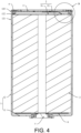
- FIG. 1 shows a cross-sectional view of the first type of cylindrical battery provided in the present disclosure.
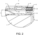
- FIG. 2 shows an enlarged view of position A in FIG. 1 .
- the cylindrical battery includes a housing 1, a cell 2, a cover 3, a sealing member 4, a first connecting piece 5, a second connecting piece 6 and an electrode pole 7.
- the housing 1 includes an opening, specifically, the housing 1 includes an end wall 11 and a surrounding wall 12, one end of the surrounding wall 12 is connected to the end wall 11, and the other end of the surrounding wall 12 forms the above-mentioned opening.
- the electrode pole 7 penetrates through the end wall 11 and is connected to the housing 1 in an insulated manner.
- the cell 2 is arranged in the housing 1, and the cover 3 is fixed on one end of the surrounding wall 12 away from the end wall 11 by adapting to the sealing member 4.
- the cell 2 includes a cell body, a first tab and a second tab.
- the first tab is located at one end of the cell body away from the end wall 11 of the housing 1, and the second tab is located at one end of the cell body close to the end wall 11 of the housing 1.
- the first tab is electrically connected to the cover 3 through the first connecting piece 5, and the second tab is electrically connected to the electrode pole 7 through the second connecting piece 6.
- the packaging process of the housing 1 and the cover 3 may be as follows: one end of the surrounding wall 12 of the housing 1 away from the end wall 11 is pier-sealed to form a main body portion 121 and a pier-sealed portion 122, then the sealing member 4 covers the peripheral side of the cover 3 to form a cover assembly, and the cover assembly is placed on the pier-sealed portion 122, and finally the surrounding wall 12 of the housing 1 is bent inwardly and fixed on the cover 3 to form the package portion 123, thereby completing packaging of the housing 1.
- the first connecting piece 5 includes a first connecting portion 51 and a second connecting portion 52 connected to each other.
- the first connecting portion 51 is electrically connected to the first tab
- the second connecting portion 52 is electrically connected to the cover 3.
- the shape of the first connecting portion 51 is disc-shaped, and one end of the second connecting portion 52 is welded to a peripheral area of the first connecting portion 51 close to the surrounding wall 12, and one end of the second connecting portion 52 is extended to the centre of the first connecting portion 51 and is welded to the cover 3.
- the first connecting piece 5 may also be formed integrally, and formed on the first connecting portion 51 by punching.
- the peripheral side of the cover 3 is wrapped through the sealing member 4, thereby realizing the sealing connection between the cover 3 and the surrounding wall 12 of the housing 1, and leakage of the electrolyte may be avoided; on the other hand, the cover 3 and the first tab are electrically connected, and then the protruding portion 30 of the cover 3 passes through the avoidance hole 40 on the sealing member 4 to be in direct contact with the package portion 123 of the surrounding wall 12, thereby ensuring that the cover 3 is electrically connected to the surrounding wall 12 of the housing 1. In this way, it is possible to ensure the stability of the electrical connection between the cover 3 and the housing 1 without having to weld the cover 3 and the housing 1. Also, the stability and safety of the cylindrical battery may be improved.
- the sealing member 4 covers the edge of the cover 3, when the housing 1 is packaged, the sealing member 4 is not easily detached from the cover 3, thereby ensuring the airtightness effect of the cover 3 and the package portion 123 of the housing 1, and avoiding electrolyte leakage, thus improving the stability and safety of cylindrical batteries.
- the peripheral side of the cover 3 is wrapped through the sealing member 4, thereby realizing the sealing connection between the cover 3 and the surrounding wall 12 of the housing 1, and leakage of the electrolyte may be avoided; on the other hand, the cover 3 and the first tab are electrically connected, and then the protruding portion 30 of the cover 3 passes through the avoidance hole 40 on the sealing member 4 to be in direct contact with the package portion 123 of the surrounding wall 12, thereby ensuring that the cover 3 is electrically connected to the surrounding wall 12 of the housing 1. In this way, it is possible to ensure the stability of the electrical connection between the cover 3 and the housing 1 without having to weld the cover 3 and the housing 1. Also, the stability and safety of the cylindrical battery may be improved.
- one end of the positioning pillar 44 is connected to the first wrapping portion 41, and the other end of the positioning pillar 44 is spaced apart from the second wrapping portion 42; or one end of the positioning pillar 44 is connected to the second wrapping portion 42, and the other end of the positioning pillar 44 is spaced apart from the first wrapping portion 41.
- the integration of the cover 3 and the sealing member 4 may also be realized by wrapping the sealing member 4 on the edge of the cover 3 and manually inserting the positioning pillar 44 into the positioning hole 31 of the cover 3.
- the sealing member 4 covers the edge of the cover 3, when the housing 1 is packaged, the sealing member 4 is not easily detached from the cover 3, thereby ensuring the airtightness effect between the cover 3 and the package portion 123 of the housing 1, and avoiding electrolyte leakage, thus improving the stability and safety of cylindrical batteries.
Landscapes
- Chemical & Material Sciences (AREA)
- Chemical Kinetics & Catalysis (AREA)
- Electrochemistry (AREA)
- General Chemical & Material Sciences (AREA)
- Sealing Battery Cases Or Jackets (AREA)
- Connection Of Batteries Or Terminals (AREA)
Abstract
Description
- The disclosure relates to the technical field of batteries, in particular to a cylindrical battery and an electronic device.
- Characterized in high energy density, high safety and low cost, cylindrical battery is now an important topic for research in the field of new energy power batteries. A cylindrical battery includes a housing, a cell, an electrode pole and a cover. The housing is a cylindrical structure with one end open. The housing includes an end wall and a surrounding wall enclosing the end wall. The cell is provided in the housing. The cover seals the open end of the housing. The first tab of the cell is welded to the housing through a connecting piece, and the electrode pole is fixed on the end wall of the housing and electrically connected with the second tab of the cell.
- In the related art, the packaging process of the cylindrical battery is as follows: after the cell is loaded into the housing, one end of the housing away from the electrode pole is pier-sealed, and the connecting piece is welded and fixed to the surrounding wall of the housing to realize electrical connection between the tab and the housing. If the welding between the connecting piece and the housing is performed in the housing, the metal shavings generated during the welding process are very likely to fall within the cell, which will affect the safety of the cell; if the welding between the connecting piece and the housing is performed outside the housing, since the position where the housing and the connecting piece correspond each other is generally close to the position where the housing is pier-sealed, as the surrounding wall of the housing is stretched and thinned after the pier-sealing treatment, if penetration welding is performed outside the housing, it is likely to cause the surrounding wall of the housing to crack, and electrolyte leakage will occur consequently.
- In light of the above, it is an urgent issue to provide a cylindrical battery to solve the above problems.
- A purpose of the present disclosure is to provide a cylindrical battery, which is able to avoid electrolyte leakage and improve the stability and safety of the cylindrical battery.
- Another purpose of the present disclosure is to provide an electronic device, and the stability and safety of the electronic device may be improved by using the above-mentioned cylindrical battery.
- In order to achieve the above purpose, the following technical solutions are provided:
- In the first aspect, a cylindrical battery is provided, which includes: a housing, which includes an opening; a cell, which includes a cell body and a first tab, and the first tab is located at one end of the cell body; a cover, the cover is electrically connected to the first tab, and a protruding portion is provided on the cover; a sealing member, which covers the edge of the cover, the sealing member is provided with an avoidance hole for the protruding portion to protrude from, and the protruding portion on the cover is able to reach out through the avoidance hole on the sealing member to be in direct contact with the housing.
- In an optional solution for the cylindrical battery, the sealing member includes a first wrapping portion and a second wrapping portion, the first wrapping portion covers the outer surface of the cover, and the second wrapping portion covers the inner surface of the cover.
- In an optional solution for the cylindrical battery, a plurality of protruding portions are arranged on the outer surface of the cover at intervals along the circumferential direction of the cover, and a plurality of avoidance holes are arranged on the first wrapping portion of the sealing member at intervals along the circumferential direction of the sealing member.
- In an optional solution for the cylindrical battery, a plurality of the protruding portions are arranged on the inner surface of the cover at intervals along the circumferential direction of the cover, and a plurality of the avoidance holes are arranged on the second wrapping portion of the sealing member at intervals along the circumferential direction of the sealing member.
- In an optional solution for the cylindrical battery, a positioning pillar is provided on the sealing member, and a positioning hole through which the positioning pillar passes is provided on the cover.
- In an optional solution for the cylindrical battery, the sealing member further includes a third wrapping portion, and the third wrapping portion is configured to connect the first wrapping portion and the second wrapping portion.
- In an optional solution for the cylindrical battery, the protruding portion is provided on the peripheral side of the cover, and the avoidance hole is provided on the third wrapping portion of the sealing member.
- In an optional solution for the cylindrical battery, a plurality of the protruding portions are arranged on the peripheral side of the cover at intervals along the circumferential direction of the cover, and a plurality of the avoidance holes are arranged on the third wrapping portion of the sealing member at intervals along the circumferential direction of the sealing member.
- In an optional solution for the cylindrical battery, one end of the positioning pillar is connected to the first wrapping portion, and another end of the positioning pillar is spaced apart from the second wrapping portion.
- In an optional solution for the cylindrical battery, one end of the positioning pillar is connected to the second wrapping portion, and another end of the positioning pillar is spaced apart from the first wrapping portion.
- In an optional solution for the cylindrical battery, the first wrapping portion and the second wrapping portion are arranged at intervals, and a gap between the first wrapping portion and the second wrapping portion serves as the avoidance hole. Two ends of the positioning pillar are respectively connected to the first wrapping portion and the second wrapping portion. One of the protruding portions encloses the outer peripheral side of the cover, and the protruding portion passes through the avoidance hole.
- In an optional solution for the cylindrical battery, the thickness of the protruding portion is greater than the thickness of the cover. In an optional solution for the cylindrical battery, the cylindrical battery further includes a first connecting piece, and the first connecting piece is configured to electrically connect the first tab and the cover.
- In a second aspect, an electronic device is provided, which includes the above-mentioned cylindrical battery.
- Compared with the related art, the advantageous effects of the present disclosure are as follows:
- The cylindrical battery provided by the present disclosure includes a housing, a cell, a cover and a sealing member. The housing includes an end wall and a surrounding wall enclosing the end wall; the cell includes a cell body and a first tab, the cover is electrically connected to the first tab, and the cover is provided with a protruding portion. The sealing member is provided with an avoidance hole for the protruding portion to protrude from. The protruding portion on the cover is able to reach out through the avoidance hole on the sealing member to be in direct contact with the surrounding wall, thereby ensuring that the cover is electrically connected to the surrounding wall of the housing. In this way, it is possible to ensure the stability of the electrical connection between the cover and the housing without having to weld the cover and the housing. Also, the stability and safety of the cylindrical battery may be improved. In addition, the sealing member wraps the peripheral side of the cover to realize the sealing connection between the cover and the surrounding wall of the housing, and electrolyte leakage may be avoided.
- The electronic device provided by the present disclosure is able to improve the stability and safety of the electronic device by using the above-mentioned cylindrical battery.
- In order to more clearly illustrate the technical solutions in the embodiments of the present disclosure, the accompanying drawings that need to be used in the description of the embodiments of the present disclosure will be briefly described below. Clearly, the accompanying drawings in the following description are only some embodiments of the present disclosure. For those skilled in the art, other drawings can also be obtained according to the content of the embodiment and these drawings of the present disclosure without any inventive effort.
-
FIG. 1 is a schematic structural diagram of the first type of cylindrical battery provided in an embodiment of the present disclosure. -
FIG. 2 is an enlarged view of position A inFIG. 1 . -
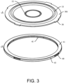
FIG. 3 is an exploded schematic diagram of a cover and a sealing member of the first type of cylindrical battery provided in an embodiment of the present disclosure. -
FIG. 4 is a schematic structural diagram of the second type of cylindrical battery provided in an embodiment of the present disclosure. -
FIG. 5 is an enlarged view of position B inFIG. 4 . -
FIG. 6 is an exploded schematic diagram of a cover and a sealing member of the second type of cylindrical battery provided in an embodiment of the present disclosure. -
FIG. 7 is a schematic structural diagram of the third type of cylindrical battery provided in an embodiment of the present disclosure. -
FIG. 8 is an enlarged view of position C inFIG. 7 . -
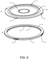
FIG. 9 is an exploded schematic diagram of a cover and a sealing member of the third type of cylindrical battery provided in an embodiment of the present disclosure. -
FIG. 10 is a schematic structural diagram of the fourth type of cylindrical battery provided in an embodiment of the present disclosure. -
FIG. 11 is an enlarged view of position D inFIG. 10 . -
FIG. 12 is an exploded schematic diagram of a cover and a sealing member of the fourth type of cylindrical battery provided in an embodiment of the present disclosure. - In order to better describe the technical problem to be solved by the disclosure, the adopted technical solution and the achieved technical effect, the technical solution of the disclosure will be further described below in conjunction with the accompanying drawings and through specific implementation methods.
- In the description of the present disclosure, unless otherwise clearly specified and limited, the terms "connected", "linked" and "fixed" should be understood in a broad sense, for example, the above terms may refer to a fixed connection, a detachable connection, or integral formation; mechanical or electrical connection; direction connection or indirect connection through an intermediary; or the internal communication of two components or the interaction relationship between two components. Those of ordinary skill in the art can understand the specific meanings of the above terms in the present disclosure in specific situations.
- In the present disclosure, unless otherwise clearly specified and limited, a first feature being "on" or "below" a second feature may indicate direct contact between the first and second features, and may also indicate that the first and second features are not in direct contact but are in indirect contact through another feature between them. Moreover, the first feature being "above", "over" and "on" the second feature indicates that the first feature is directly above and obliquely above the second feature, or merely indicates that the first feature is at a level higher than the second feature. The first feature being "below", "beneath" and "under" the second feature indicates that the first feature is directly below and obliquely below the second feature, or simply means that the first feature is at a level lower than the second feature.
- In the description of the present disclosure, the orientation or positional relationship of the terms "upper", "lower", "left", "right" is interpreted based on the orientation or positional relationship shown in the accompanying drawings, and are only for the convenience of description and simplification of operation. It does not indicate or imply that the device or element referred to must have a specific orientation, be constructed and operate in a specific orientation, and therefore should not be construed as limitation to the present disclosure. In addition, the terms "first" and "second" are only used for discrimination in description, and have no special meaning.
-
FIG. 1 shows a cross-sectional view of the first type of cylindrical battery provided in the present disclosure.FIG. 2 shows an enlarged view of position A inFIG. 1 . As shown inFIG. 1 andFIG. 2 , the cylindrical battery includes ahousing 1, acell 2, acover 3, a sealing member 4, a first connectingpiece 5, a second connectingpiece 6 and anelectrode pole 7. Thehousing 1 includes an opening, specifically, thehousing 1 includes anend wall 11 and a surroundingwall 12, one end of the surroundingwall 12 is connected to theend wall 11, and the other end of the surroundingwall 12 forms the above-mentioned opening. Theelectrode pole 7 penetrates through theend wall 11 and is connected to thehousing 1 in an insulated manner. Thecell 2 is arranged in thehousing 1, and thecover 3 is fixed on one end of the surroundingwall 12 away from theend wall 11 by adapting to the sealing member 4. Thecell 2 includes a cell body, a first tab and a second tab. The first tab is located at one end of the cell body away from theend wall 11 of thehousing 1, and the second tab is located at one end of the cell body close to theend wall 11 of thehousing 1. The first tab is electrically connected to thecover 3 through the first connectingpiece 5, and the second tab is electrically connected to theelectrode pole 7 through the second connectingpiece 6. The packaging process of thehousing 1 and thecover 3 may be as follows: one end of the surroundingwall 12 of thehousing 1 away from theend wall 11 is pier-sealed to form amain body portion 121 and a pier-sealedportion 122, then the sealing member 4 covers the peripheral side of thecover 3 to form a cover assembly, and the cover assembly is placed on the pier-sealedportion 122, and finally the surroundingwall 12 of thehousing 1 is bent inwardly and fixed on thecover 3 to form thepackage portion 123, thereby completing packaging of thehousing 1. - Further, as shown in
FIG. 2 , the first connectingpiece 5 includes a first connectingportion 51 and a second connectingportion 52 connected to each other. The first connectingportion 51 is electrically connected to the first tab, and the second connectingportion 52 is electrically connected to thecover 3. Optionally, the shape of the first connectingportion 51 is disc-shaped, and one end of the second connectingportion 52 is welded to a peripheral area of the first connectingportion 51 close to the surroundingwall 12, and one end of the second connectingportion 52 is extended to the centre of the first connectingportion 51 and is welded to thecover 3. Of course, in other embodiments, the first connectingpiece 5 may also be formed integrally, and formed on the first connectingportion 51 by punching. -
FIG. 3 is an exploded schematic diagram of a cover assembly of the first type of cylindrical battery provided in the present disclosure. As shown inFIG. 3 in conjunction withFIG. 2 , thecover 3 is provided with a protrudingportion 30, and the sealing member 4 is provided with anavoidance hole 40 for the protrudingportion 30 to protrude from. The protrudingportion 30 on thecover 3 is able to reach out through theavoidance hole 40 on the sealing member 4 to be in direct contact with thepackage portion 123 of the surroundingwall 12. In forming the cover assembly, on the one hand, the peripheral side of thecover 3 is wrapped through the sealing member 4, thereby realizing the sealing connection between thecover 3 and the surroundingwall 12 of thehousing 1, and leakage of the electrolyte may be avoided; on the other hand, thecover 3 and the first tab are electrically connected, and then the protrudingportion 30 of thecover 3 passes through theavoidance hole 40 on the sealing member 4 to be in direct contact with thepackage portion 123 of the surroundingwall 12, thereby ensuring that thecover 3 is electrically connected to the surroundingwall 12 of thehousing 1. In this way, it is possible to ensure the stability of the electrical connection between thecover 3 and thehousing 1 without having to weld thecover 3 and thehousing 1. Also, the stability and safety of the cylindrical battery may be improved. - As shown in
FIG. 3 in conjunction withFIG. 2 , the sealing member 4 includes afirst wrapping portion 41, asecond wrapping portion 42 and athird wrapping portion 43. Thefirst wrapping portion 41 covers theouter surface 301 of thecover 3, thesecond wrapping portion 42 covers theinner surface 302 of thecover 3, and thethird wrapping portion 43 is configured for connecting thefirst wrapping portion 41 and thesecond wrapping portion 42. Exemplarily, the section of the sealing member 4 is formed in a C shape. When assembling thecover 3, the sealing member 4 covers the peripheral edge of thecover 3, and then the cover assembly is placed on the pier-sealedportion 122 of thehousing 1. In this manner, it is possible to improve the assembly efficiency of thecover 3. In the meantime, since the sealing member 4 covers the edge of thecover 3, when thehousing 1 is packaged, the sealing member 4 is not easily detached from thecover 3, thereby ensuring the airtightness effect of thecover 3 and thepackage portion 123 of thehousing 1, and avoiding electrolyte leakage, thus improving the stability and safety of cylindrical batteries. - Further, as shown in
FIG. 3 , the protrudingportion 30 is provided on the peripheral side of thecover 3, and theavoidance hole 40 is provided on thethird wrapping portion 43 of the sealing member 4. Four protrudingportions 30 are arranged on the peripheral side of thecover 3 at intervals along the circumferential direction of thecover 3. Four avoidance holes 40 are arranged on thethird wrapping portion 43 of the sealing member 4 at intervals along the circumferential direction of the sealing member 4. When the sealing member 4 covers the edge of thecover 3, the protrudingportion 30 is able to reach out through theavoidance hole 40. In addition, the cooperation of the protrudingportion 30 and theavoidance hole 40 makes it possible to position the sealing member 4, thereby avoiding the deformation and dislocation of the sealing member 4 due to the pressing force when thecover 3 is packaged, and ensuring the airtightness effect of the sealing member 4 to avoid electrolyte leakage. Of course, in other embodiments, the number of protrudingportions 30 and avoidance holes 40 is not limited to the above examples, and the number of protrudingportions 30 and avoidance holes 40 may be set freely according to needs, and related details are not provided here. It should be noted that the greater the number of protrudingportions 30, the more stable the electrical connection between thecover 3 and the surroundingwall 12 of thehousing 1. However, as the number of avoidance holes 40 increases, the airtightness between thecover 3 and the surroundingwall 12 of thehousing 1 is likely to decrease, so the number of the protrudingportions 30 and avoidance holes 40 is preferably 3 to 20. - Further, as shown in
FIG. 3 , a pier-thinninggroove 32 is provided on thecover 3. The pier-thinninggroove 32 is annular, and the center of the pier-thinninggroove 32 coincides with the center of thecover 3. Regarding the setting of the pier-thinninggroove 32, in the first aspect, the pier-thinninggroove 32 reduces the structural strength of thecover 3 at this position, so that an explosion-proof valve structure may be formed at the pier-thinninggroove 32. When thermal imbalance occurs in the cylindrical battery, the pier-thinninggroove 32 breaks and releases high-temperature gas to avoid battery explosion. Secondly, the pier-thinninggroove 32 is able to reduce the weight of thecover 3, save materials, reduce material costs, and realize lightweight design of cylindrical batteries. Thecover 3 is provided with a punchingportion 33, the punchingportion 33 is annular, the center of the punchingportion 33 coincides with the center of thecover 3, and the punchingportion 33 protrudes toward theouter surface 301 of thecover 3. The arrangement of the punchingportion 33 makes it possible to improve the overall structural strength of thecover 3, and prevent thecover 3 from being deformed by force. Exemplarily, thecover 3 may be formed by punching a steel plate. -
FIG. 4 shows a cross-sectional view of the second type of cylindrical battery provided in the present disclosure.FIG. 5 shows an enlarged view of position B inFIG. 4 . As shown inFIG. 5 in conjunction withFIG. 4 , the cylindrical battery includes ahousing 1, acell 2, acover 3, a sealing member 4, a first connectingpiece 5, a second connectingpiece 6 and anelectrode pole 7. Thehousing 1 includes an opening. Specifically, thehousing 1 includes anend wall 11 and a surroundingwall 12, one end of the surroundingwall 12 is connected to theend wall 11, and the other end of the surroundingwall 12 forms the above-mentioned opening. Theelectrode pole 7 penetrates through theend wall 11 and is connected to thehousing 1 in an insulated manner. Thecell 2 is arranged in thehousing 1, and thecover 3 is fixed on one end of the surroundingwall 12 away from theend wall 11 by adapting to the sealing member 4. Thecell 2 includes a cell body, a first tab and a second tab. The first tab is located at one end of the cell body away from theend wall 11 of thehousing 1, and the second tab is located at one end of the cell body close to theend wall 11 of thehousing 1. The first tab is electrically connected to thecover 3 through the first connectingpiece 5, and the second tab is electrically connected to theelectrode pole 7 through the second connectingpiece 6. The packaging process of thehousing 1 and thecover 3 may be as follows: one end of the surroundingwall 12 of thehousing 1 away from theend wall 11 is pier-sealed to form amain body portion 121 and a pier-sealedportion 122, then the sealing member 4 covers the peripheral side of thecover 3, and the assembly body of thecover 3 and the sealing member 4 is placed on the pier-sealedportion 122, and finally the surroundingwall 12 of thehousing 1 is bent inwardly and fixed on thecover 3 to form thepackage portion 123, thereby completing packaging of thehousing 1. -
FIG. 6 shows an exploded schematic view of a cover assembly of the second type of cylindrical battery provided in the present disclosure. As shown inFIG. 6 in conjunction withFIG. 5 , thecover 3 is provided with a protrudingportion 30. The sealing member 4 is provided with anavoidance hole 40 for the protrudingportion 30 to protrude from. The protrudingportion 30 on thecover 3 is able to reach out through theavoidance hole 40 on the sealing member 4 to be in direct contact with thepackage portion 123 of the surroundingwall 12. In forming the cover assembly, on the one hand, the peripheral side of thecover 3 is wrapped through the sealing member 4, thereby realizing the sealing connection between thecover 3 and the surroundingwall 12 of thehousing 1, and leakage of the electrolyte may be avoided; on the other hand, thecover 3 and the first tab are electrically connected, and then the protrudingportion 30 of thecover 3 passes through theavoidance hole 40 on the sealing member 4 to be in direct contact with thepackage portion 123 of the surroundingwall 12, thereby ensuring that thecover 3 is electrically connected to the surroundingwall 12 of thehousing 1. In this way, it is possible to ensure the stability of the electrical connection between thecover 3 and thehousing 1 without having to weld thecover 3 and thehousing 1. Also, the stability and safety of the cylindrical battery may be improved. - A pier-thinning
groove 32 is provided on thecover 3. The pier-thinninggroove 32 is annular, and the center of the pier-thinninggroove 32 coincides with the center of thecover 3. Regarding the setting of the pier-thinninggroove 32, in the first aspect, the pier-thinninggroove 32 reduces the structural strength of thecover 3 at this position, so that an explosion-proof valve structure may be formed at the pier-thinninggroove 32. When thermal imbalance occurs in the cylindrical battery, the pier-thinninggroove 32 breaks and releases high-temperature gas to avoid battery explosion. Secondly, the pier-thinninggroove 32 is able to reduce the weight of thecover 3, save materials, reduce material costs, and realize lightweight design of cylindrical batteries. Thecover 3 is provided with a punchingportion 33, the punchingportion 33 is annular, the center of the punchingportion 33 coincides with the center of thecover 3, and the punchingportion 33 protrudes toward theouter surface 301 of thecover 3. The arrangement of the punchingportion 33 makes it possible to improve the overall structural strength of thecover 3, and prevent thecover 3 from being deformed by force. Exemplarily, thecover 3 may be formed by punching a steel plate. - The similarity in the structures of the second type of cylindrical battery and the first type of cylindrical battery will not be repeated here, and the main difference between the two lies in: the cooperation between the sealing member 4 and the
cover 3 is different. The details are as follows: - The sealing member 4 includes a
first wrapping portion 41, asecond wrapping portion 42 and athird wrapping portion 43. Thefirst wrapping portion 41 covers theouter surface 301 of thecover 3, thesecond wrapping portion 42 covers theinner surface 302 of thecover 3, and thethird wrapping portion 43 is configured to connect thefirst wrapping portion 41 and thesecond wrapping portion 42. Exemplarily, the section of the sealing member 4 is formed in a C shape. The protrudingportion 30 is provided on theouter surface 301 of thecover 3, theavoidance hole 40 is arranged on thefirst wrapping portion 41 of the sealing member 4, and the protrudingportion 30 passes through theavoidance hole 40 and then directly contacts the inner surface of thepackage portion 123 of the surroundingwall 12. - In
FIG. 6 , four protrudingportions 30 are arranged on theouter surface 301 of thecover 3 at intervals along the circumferential direction of thecover 3. Four avoidance holes 40 are arranged on thefirst wrapping portion 41 of the sealing member 4 at intervals along the circumferential direction of the sealing member 4. When the sealing member 4 covers the edge of thecover 3, the protrudingportion 30 is able to reach out through theavoidance hole 40. In addition, the cooperation of the protrudingportion 30 and theavoidance hole 40 makes it possible to position the sealing member 4, thereby avoiding the deformation and dislocation of the sealing member 4 due to the pressing force when thecover 3 is packaged, and ensuring the airtightness effect of the sealing member 4 to avoid electrolyte leakage. Of course, in other embodiments, the number of protrudingportions 30 and avoidance holes 40 is not limited to the above examples, and the number of protrudingportions 30 and avoidance holes 40 may be set freely according to needs, and related details are not provided here. It should be noted that the greater the number of protrudingportions 30, the more stable the electrical connection between thecover 3 and the surroundingwall 12 of thehousing 1. However, as the number of avoidance holes 40 increases, the airtightness between thecover 3 and the surroundingwall 12 of thehousing 1 is likely to decrease, so the number of the protrudingportions 30 and avoidance holes 40 is preferably 3 to 20. - Further, as shown in
FIG. 6 , the protrudingportion 30 is a cylindrical structure, and theavoidance hole 40 is a round through hole. In other embodiments, the protrudingportion 30 may also have other shapes, which are not limited here. - Optionally, in other embodiments, a plurality of protruding
portions 30 are arranged on theinner surface 302 of thecover 3 at intervals along the circumferential direction of thecover 3, and a plurality of avoidance holes 40 are arranged on thesecond wrapping portion 42 of the sealing member 4 at intervals along the circumferential direction of the sealing member 4. For the arrangement of the protrudingportion 30 and theavoidance hole 40, reference may be made to the arrangement of the second type of cylindrical battery, and details will not be repeated here. -
FIG. 7 is a cross-sectional view of the third type of cylindrical battery provided in the present disclosure.FIG. 8 is an enlarged view of position C inFIG. 7 . As shown inFIG. 8 combined withFIG. 7 , the cylindrical battery includes ahousing 1, acell 2, acover 3, a sealing member 4, a first connectingpiece 5, a second connectingpiece 6 and anelectrode pole 7. Thehousing 1 includes an opening, specifically, thehousing 1 includes anend wall 11 and a surroundingwall 12, one end of the surroundingwall 12 is connected to theend wall 11, and the other end of the surroundingwall 12 forms the above-mentioned opening. Theelectrode pole 7 penetrates through theend wall 11 and is connected to thehousing 1 in an insulated manner. Thecell 2 is arranged in thehousing 1, and thecover 3 is fixed on one end of the surroundingwall 12 away from theend wall 11 by adapting to the sealing member 4. Thecell 2 includes a cell body, a first tab and a second tab. The first tab is located at one end of the cell body away from theend wall 11 of thehousing 1, and the second tab is located at one end of the cell body close to theend wall 11 of thehousing 1. The first tab is electrically connected to thecover 3 through the first connectingpiece 5, and the second tab is electrically connected to theelectrode pole 7 through the second connectingpiece 6. The packaging process of thehousing 1 and thecover 3 may be as follows: one end of the surroundingwall 12 of thehousing 1 away from theend wall 11 is pier-sealed to form amain body portion 121 and a pier-sealedportion 122, then the sealing member 4 covers the peripheral side of thecover 3, and the assembly body of thecover 3 and the sealing member 4 is placed on the pier-sealedportion 122, and finally the surroundingwall 12 of thehousing 1 is bent inwardly and fixed on thecover 3 to form thepackage portion 123, thereby completing packaging of thehousing 1. -
FIG. 9 is an exploded schematic diagram of a cover assembly of the third type of cylindrical battery provided in the present disclosure. As shown inFIG. 9 combined withFIG. 8 , thecover 3 is provided with a protrudingportion 30, and the sealing member 4 is provided with anavoidance hole 40 for the protrudingportion 30 to protrude from. The protrudingportion 30 on thecover 3 is able to reach out through theavoidance hole 40 on the sealing member 4 to be in direct contact with thepackage portion 123 of the surroundingwall 12. In forming the cover assembly, on the one hand, the peripheral side of thecover 3 is wrapped through the sealing member 4, thereby realizing the sealing connection between thecover 3 and the surroundingwall 12 of thehousing 1, and leakage of the electrolyte may be avoided; on the other hand, thecover 3 and the first tab are electrically connected, and then the protrudingportion 30 of thecover 3 passes through theavoidance hole 40 on the sealing member 4 to be in direct contact with the surroundingwall 12 of thehousing 1, thereby ensuring that thecover 3 is electrically connected to the surroundingwall 12 of thehousing 1. In this way, it is possible to ensure the stability of the electrical connection between thecover 3 and thehousing 1 without having to weld thecover 3 and thehousing 1. Also, the stability and safety of the cylindrical battery may be improved. - A pier-thinning
groove 32 is provided on thecover 3. The pier-thinninggroove 32 is annular, and the center of the pier-thinninggroove 32 coincides with the center of thecover 3. Regarding the setting of the pier-thinninggroove 32, in the first aspect, the pier-thinninggroove 32 reduces the structural strength of thecover 3 at this position, so that an explosion-proof valve structure may be formed at the pier-thinninggroove 32. When thermal imbalance occurs in the cylindrical battery, the pier-thinninggroove 32 breaks and releases high-temperature gas to avoid battery explosion. Secondly, the pier-thinninggroove 32 is able to reduce the weight of thecover 3, save materials, reduce material costs, and realize lightweight design of cylindrical batteries. Thecover 3 is provided with a punchingportion 33, the punchingportion 33 is annular, the center of the punchingportion 33 coincides with the center of thecover 3, and the punchingportion 33 protrudes toward theouter surface 301 of thecover 3. The arrangement of the punchingportion 33 makes it possible to improve the overall structural strength of thecover 3, and prevent thecover 3 from being deformed by force. Exemplarily, thecover 3 may be formed by punching a steel plate. - The arrangement of the protruding
portion 30 andavoidance hole 40 in the third type of cylindrical battery is the same as that of the first type of cylindrical battery, and details will not be repeated here. The main difference between the two is that: the way of cooperation between the sealing member 4 and thecover 3 is different. The details are as follows: - The sealing member 4 includes a
first wrapping portion 41, asecond wrapping portion 42 and athird wrapping portion 43 connected in sequence. Thefirst wrapping portion 41 covers theouter surface 301 of thecover 3, thesecond wrapping portion 42 covers theinner surface 302 of thecover 3, and thethird wrapping portion 43 is configured to connect thefirst wrapping portion 41 and thesecond wrapping portion 42. Exemplarily, the section of the sealing member 4 is formed in a C shape. Thecover 3 is provided with apositioning hole 31, the sealing member 4 is provided with apositioning pillar 44, and thepositioning pillar 44 passes through thepositioning hole 31 to further position thecover 3 and the sealing member 4. - Exemplarily, as shown in
FIG. 8 andFIG. 9 , one end of thepositioning pillar 44 is connected to thefirst wrapping portion 41, and the other end of thepositioning pillar 44 is connected to thesecond wrapping portion 42. In this way, thecover 3 and the sealing member 4 may be integrally formed by injection molding. Specifically, thecover 3 serves as an embedded member, and then the sealing member 4 is integrally formed on thecover 3 by using an injection mold to realize integral molding of thecover 3 and the sealing member 4, thereby improving the assembly efficiency of the cover assembly. Of course, in other embodiments, one end of thepositioning pillar 44 is connected to thefirst wrapping portion 41, and the other end of thepositioning pillar 44 is spaced apart from thesecond wrapping portion 42; or one end of thepositioning pillar 44 is connected to thesecond wrapping portion 42, and the other end of thepositioning pillar 44 is spaced apart from thefirst wrapping portion 41. In this manner, the integration of thecover 3 and the sealing member 4 may also be realized by wrapping the sealing member 4 on the edge of thecover 3 and manually inserting thepositioning pillar 44 into thepositioning hole 31 of thecover 3. -
FIG. 10 shows a cross-sectional view of the fourth cylindrical battery provided in the present disclosure.FIG. 11 shows an enlarged view of position D inFIG. 10 . As shown inFIG. 11 in combination withFIG. 10 , the cylindrical battery includes ahousing 1, acell 2, acover 3, a sealing member 4, a first connectingpiece 5, a second connectingpiece 6 and anelectrode pole 7.
Thehousing 1 includes an opening, specifically, thehousing 1 includes anend wall 11 and a surroundingwall 12, one end of the surroundingwall 12 is connected to theend wall 11, and the other end of the surroundingwall 12 forms the above-mentioned opening. Theelectrode pole 7 penetrates through theend wall 11 and is connected to thehousing 1 in an insulated manner. Thecell 2 is arranged in thehousing 1, and thecover 3 is fixed on one end of the surroundingwall 12 away from theend wall 11 by adapting to the sealing member 4. Thecell 2 includes a cell body, a first tab and a second tab. The first tab is located at one end of the cell body away from theend wall 11 of thehousing 1, and the second tab is located at one end of the cell body close to theend wall 11 of thehousing 1. The first tab is electrically connected to thecover 3 through the first connectingpiece 5, and the second tab is electrically connected to theelectrode pole 7 through the second connectingpiece 6. The packaging process of thehousing 1 and thecover 3 may be as follows: one end of the surroundingwall 12 of thehousing 1 away from theend wall 11 is pier-sealed to form amain body portion 121 and a pier-sealedportion 122, then the sealing member 4 covers the peripheral side of thecover 3, and the assembly body of thecover 3 and the sealing member 4 is placed on the pier-sealedportion 122, and finally the surroundingwall 12 of thehousing 1 is bent inwardly and fixed on thecover 3 to form thepackage portion 123, thereby completing packaging of thehousing 1. -
FIG. 12 is an exploded schematic diagram of a cover assembly of the fourth type of cylindrical battery provided in the present disclosure. As shown inFIG. 12 combined withFIG. 11 , thecover 3 is provided with a protrudingportion 30, and the sealing member 4 is provided with anavoidance hole 40 for the protrudingportion 30 to protrude from. The protrudingportion 30 on thecover 3 is able to reach out through theavoidance hole 40 on the sealing member 4 to be in direct contact with thepackage portion 123 of the surroundingwall 12. In forming the cover assembly, on the one hand, the peripheral side of thecover 3 is wrapped through the sealing member 4, thereby realizing the sealing connection between thecover 3 and the surroundingwall 12 of thehousing 1, and leakage of the electrolyte may be avoided; on the other hand, thecover 3 and the first tab are electrically connected, and then the protrudingportion 30 of thecover 3 passes through theavoidance hole 40 on the sealing member 4 to be in direct contact with the surroundingwall 12 of thehousing 1, thereby ensuring that thecover 3 is electrically connected to the surroundingwall 12 of thehousing 1. In this way, it is possible to ensure the stability of the electrical connection between thecover 3 and thehousing 1 without having to weld thecover 3 and thehousing 1. Also, the stability and safety of the cylindrical battery may be improved. - A pier-thinning
groove 32 is provided on thecover 3. The pier-thinninggroove 32 is annular, and the center of the pier-thinninggroove 32 coincides with the center of thecover 3. Regarding the setting of the pier-thinninggroove 32, in the first aspect, the pier-thinninggroove 32 reduces the structural strength of thecover 3 at this position, so that an explosion-proof valve structure may be formed at the pier-thinninggroove 32. When thermal imbalance occurs in the cylindrical battery, the pier-thinninggroove 32 breaks and releases high-temperature gas to avoid battery explosion. Secondly, the pier-thinninggroove 32 is able to reduce the weight of thecover 3, save materials, reduce material costs, and realize lightweight design of cylindrical batteries. Thecover 3 is provided with a punchingportion 33, the punchingportion 33 is annular, the center of the punchingportion 33 coincides with the center of thecover 3, and the punchingportion 33 protrudes toward theouter surface 301 of thecover 3. The arrangement of the punchingportion 33 makes it possible to improve the overall structural strength of thecover 3, and prevent thecover 3 from being deformed by force. Exemplarily, thecover 3 may be formed by punching a steel plate. - The main difference between the fourth type of cylindrical battery and the third type of cylindrical battery is that the structures of the sealing member 4 and the
cover 3 are different. The details are as follows: - The sealing member 4 includes a
first wrapping portion 41 and asecond wrapping portion 42, the first wrapping portion covers theouter surface 301 of thecover 3, and thesecond wrapping portion 42 covers theinner surface 302 of thecover 3. Thefirst wrapping portion 41 and thesecond wrapping portion 42 are substantially parallel to each other. The sealing member 4 further includes apositioning pillar 44, which is configured to connect thefirst wrapping portion 41 and thesecond wrapping portion 42 to ensure the integrity of the sealing member 4. Thecover 3 and the sealing member 4 are integrally assembled by injection molding. Since the sealing member 4 covers the edge of thecover 3, when thehousing 1 is packaged, the sealing member 4 is not easily detached from thecover 3, thereby ensuring the airtightness effect between thecover 3 and thepackage portion 123 of thehousing 1, and avoiding electrolyte leakage, thus improving the stability and safety of cylindrical batteries. - Specifically, in this example, the number of the protruding
portion 30 is one, and one protrudingportion 30 is disposed around the peripheral side of thecover 3. The gap between thefirst wrapping portion 41 and thesecond wrapping portion 42 serves as anavoidance hole 40 for the protrudingportion 30 to pass through. The thickness of the protrudingportion 30 in the height direction of the battery is greater than that of thecover 3, thereby increasing the contact area between the protrudingportion 30 and thepackage portion 123 of the surroundingwall 12, thus ensuring the stability of the electrical connection. - As shown in
FIG. 12 in combination withFIG. 11 , the protrudingportion 30 is arranged perpendicular to thecover 3, and thus forming an inverted T shape. Thefirst wrapping portion 41 and thesecond wrapping portion 42 of the sealing member 4 are connected and fixed through thepositioning pillar 44, thereby ensuring the overall integrity of the sealing member 4. - In the fourth type of cylindrical battery, the airtightness effect of the sealing member 4 is mainly realized by the
first wrapping portion 41 and thesecond wrapping portion 42 of the sealing member 4. In this example, the contact area between the protrudingportion 30 of thecover 3 and thepackage portion 123 of thehousing 1 is the largest, and the contact effect is the most stable, thereby effectively improving the stability of the electrical connection between thecover 3 and thehousing 1. - The present disclosure further provides an electronic device, which includes the cylindrical battery. By using the cylindrical battery, the electronic device has high energy density and stable performance, and may improve user experience.
- Optionally, the electronic device may be a power battery of a new energy vehicle, a new energy storage device, an electronic product, etc., which will not be described here in details.
- Note that in the description of this present disclosure, some expressions such as "some embodiments", "other embodiments" and the like mean that the specific features, structures, materials or characteristics described in conjunction with the embodiments or examples are included in at least one embodiment or example of the disclosure. In this present disclosure, schematic expression of the above terms do not necessarily refer to the same embodiment or example. Furthermore, the particular features, structures, materials or characteristics described may be combined in any suitable manner in any one or more embodiments or examples.
Claims (11)
- A cylindrical battery, characterized by comprising:a housing (1), which comprises an opening;a cell (2), which comprises a cell body and a first tab, wherein the first tab is located at one end of the cell body;a cover (3), which is electrically connected to the first tab, wherein a protruding portion (30) is provided on the cover (3);a sealing member (4), which covers an edge of the cover (3), wherein the sealing member (4) is provided with an avoidance hole (40) for the protruding portion (30) to protrude from, and the protruding portion (30) on the cover (3) is able to reach out through the avoidance hole (40) on the sealing member (4) to be in direct contact with the housing (1).
- The cylindrical battery according to claim 1, characterized in that the sealing member (4) comprises a first wrapping portion (41) and a second wrapping portion (42), the first wrapping portion (41) covers an outer surface (301) of the cover (3), and the second wrapping portion (42) covers an inner surface (302) of the cover (3).
- The cylindrical battery according to claim 2, characterized in that a plurality of the protruding portions (30) are arranged on the outer surface (301) of the cover (3) at intervals along a circumferential direction of the cover (3), and a plurality of the avoidance holes (40) are arranged on the first wrapping portion (41) of the sealing member (4) at intervals along a circumferential direction of the sealing member (4); or
the plurality of protruding portions (30) are arranged on the inner surface (302) of the cover (3) at intervals along the circumferential direction of the cover (3), and the plurality of avoidance holes (40) are arranged on the second wrapping portion (42) of the sealing member (4) at intervals along the circumferential direction of the sealing member (4). - The cylindrical battery according to claim 2, characterized in that a positioning pillar (44) is provided on the sealing member (4), and a positioning hole (31) through which the positioning pillar (44) passes is provided on the cover (3).
- The cylindrical battery according to claim 4, characterized in that the sealing member (4) further comprises a third wrapping portion (43), and the third wrapping portion (43) is configured to connect the first wrapping portion (41) and the second wrapping portion (42).
- The cylindrical battery according to claim 5, characterized in that the protruding portion (30) is provided on a peripheral side of the cover (3), and the avoidance hole (40) is provided on the third wrapping portion (43) of the sealing member (4).
- The cylindrical battery according to claim 6, characterized in that a plurality of the protruding portions (30) are arranged on the peripheral side of the cover (3) at intervals along a circumferential direction of the cover (3), and a plurality of the avoidance holes (40) are arranged on the third wrapping portion (43) of the sealing member (4) at intervals along a circumferential direction of the sealing member (4).
- The cylindrical battery according to any one of claims 5-7, characterized in that one end of the positioning pillar (44) is connected to the first wrapping portion (41), and another end of the positioning pillar (44) is spaced apart from the second wrapping portion (42); or
one end of the positioning pillar (44) is connected to the second wrapping portion (42), and another end of the positioning pillar (44) is spaced apart from the first wrapping portion (41). - The cylindrical battery according to claim 4, characterized in that the first wrapping portion (41) and the second wrapping portion (42) are arranged at intervals, and a gap between the first wrapping portion (41) and the second wrapping portion (42) serves as the avoidance hole (40), two ends of the positioning pillar (44) are respectively connected to the first wrapping portion (41) and the second wrapping portion (42), one of the protruding portions (30) encloses an outer peripheral side of the cover (3), and the protruding portion (30) passes through the avoidance hole (40).
- The cylindrical battery according to claim 9, characterized in that a thickness of the protruding portion (30) is greater than a thickness of the cover (3).
- An electronic device, characterized by comprising the cylindrical battery according to any one of claims 1-10.
Applications Claiming Priority (1)
| Application Number | Priority Date | Filing Date | Title |
|---|---|---|---|
| CN202223550269.6U CN219203322U (en) | 2022-12-29 | 2022-12-29 | A cylindrical battery and electronic equipment |
Publications (2)
| Publication Number | Publication Date |
|---|---|
| EP4395019A1 true EP4395019A1 (en) | 2024-07-03 |
| EP4395019B1 EP4395019B1 (en) | 2025-05-14 |
Family
ID=86378454
Family Applications (1)
| Application Number | Title | Priority Date | Filing Date |
|---|---|---|---|
| EP23173050.8A Active EP4395019B1 (en) | 2022-12-29 | 2023-05-12 | Cylindrical battery and electronic device |
Country Status (5)
| Country | Link |
|---|---|
| US (1) | US20240222754A1 (en) |
| EP (1) | EP4395019B1 (en) |
| JP (1) | JP7655993B2 (en) |
| CN (1) | CN219203322U (en) |
| ES (1) | ES3031451T3 (en) |
Families Citing this family (2)
| Publication number | Priority date | Publication date | Assignee | Title |
|---|---|---|---|---|
| CN117133990B (en) * | 2023-10-25 | 2024-03-15 | 宁德时代新能源科技股份有限公司 | Protective cover and extrusion device |
| EP4576295A1 (en) * | 2023-12-21 | 2025-06-25 | SK On Co., Ltd. | Battery cell |
Citations (6)
| Publication number | Priority date | Publication date | Assignee | Title |
|---|---|---|---|---|
| US20210175568A1 (en) * | 2018-04-06 | 2021-06-10 | Panasonic Corporation | Battery |
| CN113675510A (en) * | 2021-08-17 | 2021-11-19 | 厦门海辰新能源科技有限公司 | End connection structure of battery cell, battery cell and power battery |
| CN215578778U (en) * | 2021-05-21 | 2022-01-18 | 湖北亿纬动力有限公司 | A new type of cylindrical battery |
| CN114899556A (en) * | 2022-06-02 | 2022-08-12 | 湖北亿纬动力有限公司 | Battery, battery module and battery pack |
| EP4080654A1 (en) * | 2021-02-09 | 2022-10-26 | Contemporary Amperex Technology Co., Limited | End cover assembly, cell, battery, electric apparatus, and manufacturing method |
| CN115411462A (en) * | 2022-09-21 | 2022-11-29 | 中创新航科技股份有限公司 | Battery with a battery cell |
Family Cites Families (4)
| Publication number | Priority date | Publication date | Assignee | Title |
|---|---|---|---|---|
| JP3154279B2 (en) | 1998-11-13 | 2001-04-09 | 松下電器産業株式会社 | Rechargeable battery |
| KR20110029061A (en) | 2009-09-14 | 2011-03-22 | 주식회사 엘지화학 | Secondary battery |
| JP2017059345A (en) | 2015-09-15 | 2017-03-23 | 日立オートモティブシステムズ株式会社 | Cylindrical secondary battery |
| CN113169347B (en) | 2018-11-30 | 2023-10-20 | 松下知识产权经营株式会社 | Battery cell |
-
2022
- 2022-12-29 CN CN202223550269.6U patent/CN219203322U/en active Active
-
2023
- 2023-04-23 US US18/305,372 patent/US20240222754A1/en active Pending
- 2023-05-12 EP EP23173050.8A patent/EP4395019B1/en active Active
- 2023-05-12 ES ES23173050T patent/ES3031451T3/en active Active
- 2023-08-24 JP JP2023136581A patent/JP7655993B2/en active Active
Patent Citations (6)
| Publication number | Priority date | Publication date | Assignee | Title |
|---|---|---|---|---|
| US20210175568A1 (en) * | 2018-04-06 | 2021-06-10 | Panasonic Corporation | Battery |
| EP4080654A1 (en) * | 2021-02-09 | 2022-10-26 | Contemporary Amperex Technology Co., Limited | End cover assembly, cell, battery, electric apparatus, and manufacturing method |
| CN215578778U (en) * | 2021-05-21 | 2022-01-18 | 湖北亿纬动力有限公司 | A new type of cylindrical battery |
| CN113675510A (en) * | 2021-08-17 | 2021-11-19 | 厦门海辰新能源科技有限公司 | End connection structure of battery cell, battery cell and power battery |
| CN114899556A (en) * | 2022-06-02 | 2022-08-12 | 湖北亿纬动力有限公司 | Battery, battery module and battery pack |
| CN115411462A (en) * | 2022-09-21 | 2022-11-29 | 中创新航科技股份有限公司 | Battery with a battery cell |
Also Published As
| Publication number | Publication date |
|---|---|
| JP2024095954A (en) | 2024-07-11 |
| CN219203322U (en) | 2023-06-16 |
| JP7655993B2 (en) | 2025-04-02 |
| EP4395019B1 (en) | 2025-05-14 |
| ES3031451T3 (en) | 2025-07-08 |
| US20240222754A1 (en) | 2024-07-04 |
Similar Documents
| Publication | Publication Date | Title |
|---|---|---|
| CN109659454B (en) | Top cover assembly of secondary battery and secondary battery | |
| US7781088B2 (en) | Non-aqueous electrolyte secondary cell | |
| US9722219B2 (en) | Battery, assembled battery, and mounting device | |
| CN109659453B (en) | Secondary cell's top cap subassembly and secondary cell | |
| US10818882B2 (en) | Secondary battery and battery module | |
| EP2727174B1 (en) | Electrode terminal, cover assembly and battery comprising the cover assembly | |
| US12294120B2 (en) | Top cap assembly, secondary battery, battery module and device | |
| EP4395019B1 (en) | Cylindrical battery and electronic device | |
| KR101243398B1 (en) | Rechargeable battery | |
| US20240405353A1 (en) | Explosion-proof valve, cover plate of battery and battery | |
| WO2016104734A1 (en) | Power storage element | |
| KR20020071179A (en) | Secondary battery and the fabrication method therof | |
| US20240162536A1 (en) | Battery top cover assembly | |
| US20250158178A1 (en) | Battery, battery module, and electric device | |
| JP2010272389A (en) | Sealed battery | |
| CN116207412A (en) | Battery, battery module and electric equipment | |
| KR102844136B1 (en) | Battery pack, and Vehicle including the same | |
| GB2623391A (en) | Power battery top cover structure | |
| CN116544571B (en) | Top cap subassembly, energy memory and consumer | |
| CN219457811U (en) | A battery, battery module and electrical equipment | |
| CN207690845U (en) | Secondary cell cap assembly, secondary cell and automobile | |
| US20240170773A1 (en) | Top cover structure and battery | |
| KR20200007273A (en) | Method of manufacturing cylindricality can for secondary battery and secondary battery comprising the same | |
| CN223066289U (en) | Battery cover structure and battery | |
| CN221304830U (en) | Shell, square shell battery and battery pack |
Legal Events
| Date | Code | Title | Description |
|---|---|---|---|
| PUAI | Public reference made under article 153(3) epc to a published international application that has entered the european phase |
Free format text: ORIGINAL CODE: 0009012 |
|
| STAA | Information on the status of an ep patent application or granted ep patent |
Free format text: STATUS: REQUEST FOR EXAMINATION WAS MADE |
|
| 17P | Request for examination filed |
Effective date: 20230512 |
|
| AK | Designated contracting states |
Kind code of ref document: A1 Designated state(s): AL AT BE BG CH CY CZ DE DK EE ES FI FR GB GR HR HU IE IS IT LI LT LU LV MC ME MK MT NL NO PL PT RO RS SE SI SK SM TR |
|
| RIC1 | Information provided on ipc code assigned before grant |
Ipc: H01M 50/56 20210101ALI20241104BHEP Ipc: H01M 50/545 20210101ALI20241104BHEP Ipc: H01M 50/186 20210101ALI20241104BHEP Ipc: H01M 50/184 20210101ALI20241104BHEP Ipc: H01M 50/171 20210101ALI20241104BHEP Ipc: H01M 50/152 20210101ALI20241104BHEP Ipc: H01M 50/107 20210101AFI20241104BHEP |
|
| GRAP | Despatch of communication of intention to grant a patent |
Free format text: ORIGINAL CODE: EPIDOSNIGR1 |
|
| STAA | Information on the status of an ep patent application or granted ep patent |
Free format text: STATUS: GRANT OF PATENT IS INTENDED |
|
| INTG | Intention to grant announced |
Effective date: 20250113 |
|
| P01 | Opt-out of the competence of the unified patent court (upc) registered |
Free format text: CASE NUMBER: APP_6992/2025 Effective date: 20250211 |
|
| GRAS | Grant fee paid |
Free format text: ORIGINAL CODE: EPIDOSNIGR3 |
|
| GRAA | (expected) grant |
Free format text: ORIGINAL CODE: 0009210 |
|
| STAA | Information on the status of an ep patent application or granted ep patent |
Free format text: STATUS: THE PATENT HAS BEEN GRANTED |
|
| AK | Designated contracting states |
Kind code of ref document: B1 Designated state(s): AL AT BE BG CH CY CZ DE DK EE ES FI FR GB GR HR HU IE IS IT LI LT LU LV MC ME MK MT NL NO PL PT RO RS SE SI SK SM TR |
|
| REG | Reference to a national code |
Ref country code: GB Ref legal event code: FG4D |
|
| REG | Reference to a national code |
Ref country code: CH Ref legal event code: EP |
|
| REG | Reference to a national code |
Ref country code: IE Ref legal event code: FG4D |
|
| REG | Reference to a national code |
Ref country code: DE Ref legal event code: R096 Ref document number: 602023003430 Country of ref document: DE |
|
| REG | Reference to a national code |
Ref country code: ES Ref legal event code: FG2A Ref document number: 3031451 Country of ref document: ES Kind code of ref document: T3 Effective date: 20250708 |
|
| REG | Reference to a national code |
Ref country code: NL Ref legal event code: MP Effective date: 20250514 |
|
| PG25 | Lapsed in a contracting state [announced via postgrant information from national office to epo] |
Ref country code: FI Free format text: LAPSE BECAUSE OF FAILURE TO SUBMIT A TRANSLATION OF THE DESCRIPTION OR TO PAY THE FEE WITHIN THE PRESCRIBED TIME-LIMIT Effective date: 20250514 Ref country code: PT Free format text: LAPSE BECAUSE OF FAILURE TO SUBMIT A TRANSLATION OF THE DESCRIPTION OR TO PAY THE FEE WITHIN THE PRESCRIBED TIME-LIMIT Effective date: 20250915 |
|
| REG | Reference to a national code |
Ref country code: LT Ref legal event code: MG9D |
|
| PG25 | Lapsed in a contracting state [announced via postgrant information from national office to epo] |
Ref country code: NO Free format text: LAPSE BECAUSE OF FAILURE TO SUBMIT A TRANSLATION OF THE DESCRIPTION OR TO PAY THE FEE WITHIN THE PRESCRIBED TIME-LIMIT Effective date: 20250814 Ref country code: GR Free format text: LAPSE BECAUSE OF FAILURE TO SUBMIT A TRANSLATION OF THE DESCRIPTION OR TO PAY THE FEE WITHIN THE PRESCRIBED TIME-LIMIT Effective date: 20250815 |
|
| PG25 | Lapsed in a contracting state [announced via postgrant information from national office to epo] |
Ref country code: PL Free format text: LAPSE BECAUSE OF FAILURE TO SUBMIT A TRANSLATION OF THE DESCRIPTION OR TO PAY THE FEE WITHIN THE PRESCRIBED TIME-LIMIT Effective date: 20250514 Ref country code: NL Free format text: LAPSE BECAUSE OF FAILURE TO SUBMIT A TRANSLATION OF THE DESCRIPTION OR TO PAY THE FEE WITHIN THE PRESCRIBED TIME-LIMIT Effective date: 20250514 |
|
| REG | Reference to a national code |
Ref country code: AT Ref legal event code: MK05 Ref document number: 1795617 Country of ref document: AT Kind code of ref document: T Effective date: 20250514 |
|
| PG25 | Lapsed in a contracting state [announced via postgrant information from national office to epo] |
Ref country code: BG Free format text: LAPSE BECAUSE OF FAILURE TO SUBMIT A TRANSLATION OF THE DESCRIPTION OR TO PAY THE FEE WITHIN THE PRESCRIBED TIME-LIMIT Effective date: 20250514 |
|
| PG25 | Lapsed in a contracting state [announced via postgrant information from national office to epo] |
Ref country code: HR Free format text: LAPSE BECAUSE OF FAILURE TO SUBMIT A TRANSLATION OF THE DESCRIPTION OR TO PAY THE FEE WITHIN THE PRESCRIBED TIME-LIMIT Effective date: 20250514 |
|
| PG25 | Lapsed in a contracting state [announced via postgrant information from national office to epo] |
Ref country code: AT Free format text: LAPSE BECAUSE OF FAILURE TO SUBMIT A TRANSLATION OF THE DESCRIPTION OR TO PAY THE FEE WITHIN THE PRESCRIBED TIME-LIMIT Effective date: 20250514 |
|
| PG25 | Lapsed in a contracting state [announced via postgrant information from national office to epo] |
Ref country code: RS Free format text: LAPSE BECAUSE OF FAILURE TO SUBMIT A TRANSLATION OF THE DESCRIPTION OR TO PAY THE FEE WITHIN THE PRESCRIBED TIME-LIMIT Effective date: 20250814 |
|
| PG25 | Lapsed in a contracting state [announced via postgrant information from national office to epo] |
Ref country code: IS Free format text: LAPSE BECAUSE OF FAILURE TO SUBMIT A TRANSLATION OF THE DESCRIPTION OR TO PAY THE FEE WITHIN THE PRESCRIBED TIME-LIMIT Effective date: 20250914 |
|
| PG25 | Lapsed in a contracting state [announced via postgrant information from national office to epo] |
Ref country code: LV Free format text: LAPSE BECAUSE OF FAILURE TO SUBMIT A TRANSLATION OF THE DESCRIPTION OR TO PAY THE FEE WITHIN THE PRESCRIBED TIME-LIMIT Effective date: 20250514 |
|
| PG25 | Lapsed in a contracting state [announced via postgrant information from national office to epo] |
Ref country code: DK Free format text: LAPSE BECAUSE OF FAILURE TO SUBMIT A TRANSLATION OF THE DESCRIPTION OR TO PAY THE FEE WITHIN THE PRESCRIBED TIME-LIMIT Effective date: 20250514 Ref country code: SM Free format text: LAPSE BECAUSE OF FAILURE TO SUBMIT A TRANSLATION OF THE DESCRIPTION OR TO PAY THE FEE WITHIN THE PRESCRIBED TIME-LIMIT Effective date: 20250514 |
|
| PG25 | Lapsed in a contracting state [announced via postgrant information from national office to epo] |
Ref country code: CZ Free format text: LAPSE BECAUSE OF FAILURE TO SUBMIT A TRANSLATION OF THE DESCRIPTION OR TO PAY THE FEE WITHIN THE PRESCRIBED TIME-LIMIT Effective date: 20250514 |
|
| PG25 | Lapsed in a contracting state [announced via postgrant information from national office to epo] |
Ref country code: EE Free format text: LAPSE BECAUSE OF FAILURE TO SUBMIT A TRANSLATION OF THE DESCRIPTION OR TO PAY THE FEE WITHIN THE PRESCRIBED TIME-LIMIT Effective date: 20250514 |
|
| PG25 | Lapsed in a contracting state [announced via postgrant information from national office to epo] |
Ref country code: SK Free format text: LAPSE BECAUSE OF FAILURE TO SUBMIT A TRANSLATION OF THE DESCRIPTION OR TO PAY THE FEE WITHIN THE PRESCRIBED TIME-LIMIT Effective date: 20250514 |
|
| PG25 | Lapsed in a contracting state [announced via postgrant information from national office to epo] |
Ref country code: IT Free format text: LAPSE BECAUSE OF FAILURE TO SUBMIT A TRANSLATION OF THE DESCRIPTION OR TO PAY THE FEE WITHIN THE PRESCRIBED TIME-LIMIT Effective date: 20250514 |
|
| REG | Reference to a national code |
Ref country code: DE Ref legal event code: R097 Ref document number: 602023003430 Country of ref document: DE |
|
| PLBE | No opposition filed within time limit |
Free format text: ORIGINAL CODE: 0009261 |
|
| STAA | Information on the status of an ep patent application or granted ep patent |
Free format text: STATUS: NO OPPOSITION FILED WITHIN TIME LIMIT |
|
| REG | Reference to a national code |
Ref country code: CH Ref legal event code: L10 Free format text: ST27 STATUS EVENT CODE: U-0-0-L10-L00 (AS PROVIDED BY THE NATIONAL OFFICE) Effective date: 20260325 |
|
| PGFP | Annual fee paid to national office [announced via postgrant information from national office to epo] |
Ref country code: FR Payment date: 20260323 Year of fee payment: 4 |
|
| 26N | No opposition filed |
Effective date: 20260217 |