EP4395001A1 - Voltage acquisition structure, and battery module having voltage acquisition structure - Google Patents
Voltage acquisition structure, and battery module having voltage acquisition structure Download PDFInfo
- Publication number
- EP4395001A1 EP4395001A1 EP22913910.0A EP22913910A EP4395001A1 EP 4395001 A1 EP4395001 A1 EP 4395001A1 EP 22913910 A EP22913910 A EP 22913910A EP 4395001 A1 EP4395001 A1 EP 4395001A1
- Authority
- EP
- European Patent Office
- Prior art keywords
- voltage collection
- battery core
- circuit board
- subsegment
- segment
- Prior art date
- Legal status (The legal status is an assumption and is not a legal conclusion. Google has not performed a legal analysis and makes no representation as to the accuracy of the status listed.)
- Pending
Links
- 238000006073 displacement reaction Methods 0.000 claims abstract description 9
- PXHVJJICTQNCMI-UHFFFAOYSA-N Nickel Chemical compound [Ni] PXHVJJICTQNCMI-UHFFFAOYSA-N 0.000 description 23
- 229910052759 nickel Inorganic materials 0.000 description 11
- 238000003466 welding Methods 0.000 description 8
- 238000010586 diagram Methods 0.000 description 6
- 230000007704 transition Effects 0.000 description 6
- 230000009286 beneficial effect Effects 0.000 description 3
- 230000001154 acute effect Effects 0.000 description 2
- 238000004519 manufacturing process Methods 0.000 description 2
- 239000000463 material Substances 0.000 description 2
- 238000000034 method Methods 0.000 description 2
- 230000002093 peripheral effect Effects 0.000 description 2
- 230000008569 process Effects 0.000 description 2
- 229910000990 Ni alloy Inorganic materials 0.000 description 1
- 230000009471 action Effects 0.000 description 1
- 230000003139 buffering effect Effects 0.000 description 1
- 238000004891 communication Methods 0.000 description 1
- 230000007547 defect Effects 0.000 description 1
- 238000009826 distribution Methods 0.000 description 1
- 230000005489 elastic deformation Effects 0.000 description 1
- 238000005516 engineering process Methods 0.000 description 1
- 238000004880 explosion Methods 0.000 description 1
- 238000009434 installation Methods 0.000 description 1
- 230000002452 interceptive effect Effects 0.000 description 1
- 238000012986 modification Methods 0.000 description 1
- 230000004048 modification Effects 0.000 description 1
Images




Classifications
-
- H—ELECTRICITY
- H01—ELECTRIC ELEMENTS
- H01M—PROCESSES OR MEANS, e.g. BATTERIES, FOR THE DIRECT CONVERSION OF CHEMICAL ENERGY INTO ELECTRICAL ENERGY
- H01M10/00—Secondary cells; Manufacture thereof
- H01M10/42—Methods or arrangements for servicing or maintenance of secondary cells or secondary half-cells
- H01M10/425—Structural combination with electronic components, e.g. electronic circuits integrated to the outside of the casing
-
- H—ELECTRICITY
- H01—ELECTRIC ELEMENTS
- H01M—PROCESSES OR MEANS, e.g. BATTERIES, FOR THE DIRECT CONVERSION OF CHEMICAL ENERGY INTO ELECTRICAL ENERGY
- H01M10/00—Secondary cells; Manufacture thereof
- H01M10/42—Methods or arrangements for servicing or maintenance of secondary cells or secondary half-cells
- H01M10/48—Accumulators combined with arrangements for measuring, testing or indicating the condition of cells, e.g. the level or density of the electrolyte
- H01M10/482—Accumulators combined with arrangements for measuring, testing or indicating the condition of cells, e.g. the level or density of the electrolyte for several batteries or cells simultaneously or sequentially
-
- H—ELECTRICITY
- H01—ELECTRIC ELEMENTS
- H01M—PROCESSES OR MEANS, e.g. BATTERIES, FOR THE DIRECT CONVERSION OF CHEMICAL ENERGY INTO ELECTRICAL ENERGY
- H01M50/00—Constructional details or processes of manufacture of the non-active parts of electrochemical cells other than fuel cells, e.g. hybrid cells
- H01M50/20—Mountings; Secondary casings or frames; Racks, modules or packs; Suspension devices; Shock absorbers; Transport or carrying devices; Holders
- H01M50/204—Racks, modules or packs for multiple batteries or multiple cells
-
- H—ELECTRICITY
- H01—ELECTRIC ELEMENTS
- H01M—PROCESSES OR MEANS, e.g. BATTERIES, FOR THE DIRECT CONVERSION OF CHEMICAL ENERGY INTO ELECTRICAL ENERGY
- H01M50/00—Constructional details or processes of manufacture of the non-active parts of electrochemical cells other than fuel cells, e.g. hybrid cells
- H01M50/20—Mountings; Secondary casings or frames; Racks, modules or packs; Suspension devices; Shock absorbers; Transport or carrying devices; Holders
- H01M50/284—Mountings; Secondary casings or frames; Racks, modules or packs; Suspension devices; Shock absorbers; Transport or carrying devices; Holders with incorporated circuit boards, e.g. printed circuit boards [PCB]
-
- H—ELECTRICITY
- H01—ELECTRIC ELEMENTS
- H01M—PROCESSES OR MEANS, e.g. BATTERIES, FOR THE DIRECT CONVERSION OF CHEMICAL ENERGY INTO ELECTRICAL ENERGY
- H01M50/00—Constructional details or processes of manufacture of the non-active parts of electrochemical cells other than fuel cells, e.g. hybrid cells
- H01M50/20—Mountings; Secondary casings or frames; Racks, modules or packs; Suspension devices; Shock absorbers; Transport or carrying devices; Holders
- H01M50/289—Mountings; Secondary casings or frames; Racks, modules or packs; Suspension devices; Shock absorbers; Transport or carrying devices; Holders characterised by spacing elements or positioning means within frames, racks or packs
-
- H—ELECTRICITY
- H01—ELECTRIC ELEMENTS
- H01M—PROCESSES OR MEANS, e.g. BATTERIES, FOR THE DIRECT CONVERSION OF CHEMICAL ENERGY INTO ELECTRICAL ENERGY
- H01M50/00—Constructional details or processes of manufacture of the non-active parts of electrochemical cells other than fuel cells, e.g. hybrid cells
- H01M50/50—Current conducting connections for cells or batteries
- H01M50/502—Interconnectors for connecting terminals of adjacent batteries; Interconnectors for connecting cells outside a battery casing
- H01M50/503—Interconnectors for connecting terminals of adjacent batteries; Interconnectors for connecting cells outside a battery casing characterised by the shape of the interconnectors
-
- H—ELECTRICITY
- H01—ELECTRIC ELEMENTS
- H01M—PROCESSES OR MEANS, e.g. BATTERIES, FOR THE DIRECT CONVERSION OF CHEMICAL ENERGY INTO ELECTRICAL ENERGY
- H01M50/00—Constructional details or processes of manufacture of the non-active parts of electrochemical cells other than fuel cells, e.g. hybrid cells
- H01M50/50—Current conducting connections for cells or batteries
- H01M50/502—Interconnectors for connecting terminals of adjacent batteries; Interconnectors for connecting cells outside a battery casing
- H01M50/507—Interconnectors for connecting terminals of adjacent batteries; Interconnectors for connecting cells outside a battery casing comprising an arrangement of two or more busbars within a container structure, e.g. busbar modules
-
- H—ELECTRICITY
- H01—ELECTRIC ELEMENTS
- H01M—PROCESSES OR MEANS, e.g. BATTERIES, FOR THE DIRECT CONVERSION OF CHEMICAL ENERGY INTO ELECTRICAL ENERGY
- H01M50/00—Constructional details or processes of manufacture of the non-active parts of electrochemical cells other than fuel cells, e.g. hybrid cells
- H01M50/50—Current conducting connections for cells or batteries
- H01M50/543—Terminals
- H01M50/547—Terminals characterised by the disposition of the terminals on the cells
- H01M50/548—Terminals characterised by the disposition of the terminals on the cells on opposite sides of the cell
-
- H—ELECTRICITY
- H01—ELECTRIC ELEMENTS
- H01M—PROCESSES OR MEANS, e.g. BATTERIES, FOR THE DIRECT CONVERSION OF CHEMICAL ENERGY INTO ELECTRICAL ENERGY
- H01M50/00—Constructional details or processes of manufacture of the non-active parts of electrochemical cells other than fuel cells, e.g. hybrid cells
- H01M50/50—Current conducting connections for cells or batteries
- H01M50/569—Constructional details of current conducting connections for detecting conditions inside cells or batteries, e.g. details of voltage sensing terminals
-
- H—ELECTRICITY
- H01—ELECTRIC ELEMENTS
- H01M—PROCESSES OR MEANS, e.g. BATTERIES, FOR THE DIRECT CONVERSION OF CHEMICAL ENERGY INTO ELECTRICAL ENERGY
- H01M50/00—Constructional details or processes of manufacture of the non-active parts of electrochemical cells other than fuel cells, e.g. hybrid cells
- H01M50/50—Current conducting connections for cells or batteries
- H01M50/572—Means for preventing undesired use or discharge
- H01M50/584—Means for preventing undesired use or discharge for preventing incorrect connections inside or outside the batteries
- H01M50/586—Means for preventing undesired use or discharge for preventing incorrect connections inside or outside the batteries inside the batteries, e.g. incorrect connections of electrodes
-
- H—ELECTRICITY
- H01—ELECTRIC ELEMENTS
- H01M—PROCESSES OR MEANS, e.g. BATTERIES, FOR THE DIRECT CONVERSION OF CHEMICAL ENERGY INTO ELECTRICAL ENERGY
- H01M2200/00—Safety devices for primary or secondary batteries
-
- H—ELECTRICITY
- H01—ELECTRIC ELEMENTS
- H01M—PROCESSES OR MEANS, e.g. BATTERIES, FOR THE DIRECT CONVERSION OF CHEMICAL ENERGY INTO ELECTRICAL ENERGY
- H01M2220/00—Batteries for particular applications
- H01M2220/20—Batteries in motive systems, e.g. vehicle, ship, plane
-
- H—ELECTRICITY
- H01—ELECTRIC ELEMENTS
- H01M—PROCESSES OR MEANS, e.g. BATTERIES, FOR THE DIRECT CONVERSION OF CHEMICAL ENERGY INTO ELECTRICAL ENERGY
- H01M50/00—Constructional details or processes of manufacture of the non-active parts of electrochemical cells other than fuel cells, e.g. hybrid cells
- H01M50/20—Mountings; Secondary casings or frames; Racks, modules or packs; Suspension devices; Shock absorbers; Transport or carrying devices; Holders
- H01M50/204—Racks, modules or packs for multiple batteries or multiple cells
- H01M50/207—Racks, modules or packs for multiple batteries or multiple cells characterised by their shape
- H01M50/209—Racks, modules or packs for multiple batteries or multiple cells characterised by their shape adapted for prismatic or rectangular cells
-
- Y—GENERAL TAGGING OF NEW TECHNOLOGICAL DEVELOPMENTS; GENERAL TAGGING OF CROSS-SECTIONAL TECHNOLOGIES SPANNING OVER SEVERAL SECTIONS OF THE IPC; TECHNICAL SUBJECTS COVERED BY FORMER USPC CROSS-REFERENCE ART COLLECTIONS [XRACs] AND DIGESTS
- Y02—TECHNOLOGIES OR APPLICATIONS FOR MITIGATION OR ADAPTATION AGAINST CLIMATE CHANGE
- Y02E—REDUCTION OF GREENHOUSE GAS [GHG] EMISSIONS, RELATED TO ENERGY GENERATION, TRANSMISSION OR DISTRIBUTION
- Y02E60/00—Enabling technologies; Technologies with a potential or indirect contribution to GHG emissions mitigation
- Y02E60/10—Energy storage using batteries
Definitions
- the third subsegment is bent and connected to the first subsegment and the second subsegment respectively.
- a battery module including multiple battery cores and the voltage collection structure described in the embodiments of the first aspect of the present disclosure.
- each battery core includes a conductive housing and a battery core body that is arranged in the conductive housing.
- the battery core has a first end and second end that are opposite to each other.
- the battery core body has a first end pole that is arranged on the first end and a second end pole that is arranged on the second end, and the first end pole is connected to the conductive housing.
- the voltage collection structure is arranged on the second end. A part of the multiple voltage collection sheets are connected to the second end poles, and another part of the multiple voltage collection sheets are connected to the conductive housings.
- the battery module further includes: at least one first connection sheet, each first connection sheet connecting first end poles of two adjacent battery cores, where the multiple battery cores are arranged along a thickness direction of the battery cores, and polarities of first end poles of adjacent battery cores are opposite and polarities of second end poles are opposite; and at least one second connection sheet, each second connection sheet connecting second end poles of two adjacent battery cores, and the multiple battery cores being connected in series through the at least one first connection sheet and the at least one second connection sheet, where the second connection sheet is located between the fixed holder and the circuit board, and the part of the multiple voltage collection sheets are connected to the second end poles through the second connection sheet.
- orientation or position relationships indicated by the terms such as “center”, “longitudinal”, “transverse”, “length”, “width”, “thickness”, “on”, “below”, “front”, “rear”, “left”, “right”, “vertical”, “horizontal”, “top”, “bottom”, “inside”, “outside”, “clockwise”, “counterclockwise”, “axial direction”, “radial direction”, and “circumferential direction” are based on orientation or position relationships shown in the accompanying drawings, and are used only for ease and brevity of illustration and description of the present disclosure, rather than indicating or implying that the mentioned apparatus or component needs to have a particular orientation or needs to be constructed and operated in a particular orientation. Therefore, such terms should not be construed as a limitation to the present disclosure.
- the voltage collection structure 1 includes a fixed holder 100, a circuit board 200, and multiple voltage collection sheets 300.
- a maximum protruding distance A of the buffer segment 310 ranges from 0.5 mm to 20 mm. In this way, when a maximum height difference between the multiple battery cores 2 is less than 10 mm, that is, when a height difference between any two of the battery cores 2 is less than 10 mm, under an action force of the assembly tool, the buffer segment 310 can be deformed to effectively absorb the height difference between the battery cores 2. In other words, the voltage collection sheet 300 is tightly attached to the battery core 2 to improve a yield of a battery module 3, making voltage collection of the multiple battery cores 2 more reliable.
- a maximum distance A between the portion of the buffer segment 310 and the circuit board connection segment 320 in the thickness direction of the voltage collection sheet 300 ranges from 0.5 mm to 20 mm.
- Two ends of the third subsegment 313 are respectively connected to a second end 311b of the first subsegment 311 and a second end 312b of the second subsegment 312. It should be noted that, in the present disclosure, the thickness direction of the circuit board connection segment 320, the thickness direction of the battery core connection segment 330, and the thickness direction of the voltage collection sheet 300 are consistent.
- arc-shaped transitions may be respectively located at the first subsegment 311 and the second subsegment 312.
- a location of the arc-shaped transition is not limited, provided that a protrusion can be formed to allow the voltage collection sheet 300 to have a displacement allowance in the direction that is close to the battery core 2.
- the two ends of the third subsegment 313 may be in arc-shaped transition with the first subsegment 311 and the second subsegment 312 respectively.
- the third subsegment 313 is bent and connected to the first subsegment 311 and the second subsegment 312 respectively. In this way, stress concentration in the buffer segment 310 itself and between the buffer segment 310 and the circuit board connection segment 320 as well as the battery core connection segment 330 can be avoided, and stress distribution is more even.
- a first buckle 110 and a second buckle 120 are arranged on a side of the fixed holder 100 that faces away from the battery core 2.
- the first buckle 110 is configured to be clamped onto a side of the circuit board 200 that faces away from the battery core 2.
- Multiple through holes 130 are provided on the fixed holder 100 along a thickness direction thereof. Poles of the multiple battery cores 2 are respectively inserted into the multiple through holes 130 (for example, a first end pole 411 or a second end pole 412 of a battery core body 500 is inserted into a corresponding through hole 130), and an outer peripheral surface of a portion of each pole that passes through the through hole 130 is clamped by the second buckle 120.
- multiple positioning grooves 440 are provided on the side of the fixed holder 100 that faces away from the battery core 2.
- the second end pole 412 passes through a bottom of the positioning groove 440.
- a portion of the second connection sheet 430 is located in the positioning groove 440 and connected to the second end pole 412.
- the through hole 130 is constructed at the bottom of the positioning groove 440.
Landscapes
- Chemical & Material Sciences (AREA)
- Chemical Kinetics & Catalysis (AREA)
- Electrochemistry (AREA)
- General Chemical & Material Sciences (AREA)
- Engineering & Computer Science (AREA)
- Manufacturing & Machinery (AREA)
- Microelectronics & Electronic Packaging (AREA)
- Battery Mounting, Suspending (AREA)
- Connection Of Batteries Or Terminals (AREA)
Abstract
Description
- The present disclosure claims priority to
Chinese Patent Application No. 202123317998.2, filed on December 27, 2021 - The present disclosure relates to the field of battery technologies, and more specifically, to a voltage collection structure and a battery module having the voltage collection structure.
- With an increasing number of electric vehicles, a safety issue of a power battery is increasingly concerned. A battery module usually includes a collection structure that collects a voltage of a battery core. The collection structure usually includes a collector having a collection nickel sheet. The collection nickel sheet is connected to a positive electrode and a negative electrode of each battery core, and is configured to collect a voltage of a battery core in the battery module, to detect whether the power battery is safe.
- Due to a manufacturing tolerance of the battery core itself and an assembly tolerance generated after battery cores are stacked, a gap exists between the collection nickel sheet and the battery core. As a result, the collection nickel sheet cannot be attached to the battery core effectively. The battery core and the collection nickel sheet are generally fixed by laser welding, and the laser welding requires a gap between welded workpieces to be kept within 0.5 m. When the gap between the welded workpieces is greater than 0.5 m, it causes poor welding, such as an explosion, false welding, and the like.
- In the related art, due to an unreasonable structure of the collection nickel sheet, when a tool is used to compress the collection nickel sheet during welding, the collection nickel sheet cannot provide an effective buffer space, resulting in a minimal deformation allowance for the collection nickel sheet. When a height difference exists between battery cores after the battery cores are stacked, because the collection nickel sheet has no deformation allowance when being compressed downwards by the tool during welding, the collection nickel sheet cannot absorb the height difference, resulting in a high defect rate of the battery module during assembly and welding, and further affecting the reliability of voltage collection of the battery module.
- According to the embodiments of a first aspect of the present disclosure, a voltage collection structure is provided, including: a fixed holder, where the fixed holder is configured to be connected to multiple battery cores; a circuit board, where the circuit board is installed on a side of the fixed holder that is away from the multiple battery cores; and multiple voltage collection sheets, where the multiple voltage collection sheets are installed on the circuit board and connected to the multiple battery cores. The voltage collection sheet includes a buffer segment, and at least a portion of the buffer segment protrudes in a direction that faces away from the battery core, so that the voltage collection sheet has a displacement allowance in a direction that is close to the battery core. A maximum protruding distance of the buffer segment ranges from 0.5 mm to 20 mm.
- According to some embodiments of the present disclosure, a dimension of the at least portion of the buffer segment in a width direction of the voltage collection sheet ranges from 2 mm to 20 mm, and a dimension in an extension direction of the voltage collection sheet ranges from 0.5 mm to 20 mm.
- According to some embodiments of the present disclosure, the voltage collection sheet further includes: a circuit board connection segment, where the circuit board connection segment is connected to the circuit board and an end of the buffer segment; and a battery core connection segment, where the battery core connection segment is configured to be connected to the battery core and another end of the buffer segment. The battery core connection segment and the circuit board connection segment are parallel and located in different planes. A portion of the buffer segment is located on a side of the circuit board connection segment that faces away from the battery core connection segment in a thickness direction of the voltage collection sheet, so that the battery core connection segment has a displacement allowance in the direction that is close to the battery core. A maximum distance between the portion of the buffer segment and the circuit board connection segment in the thickness direction of the voltage collection sheet ranges from 0.5 mm to 20 mm.
- According to some embodiments of the present disclosure, the buffer segment includes: a first subsegment, where a first end of the first subsegment is connected to an end of the circuit board connection segment that is adjacent to the battery core connection segment, and the first subsegment extends in a direction that is away from the battery core connection segment in a thickness direction of the circuit board connection segment; a second subsegment, where a first end of the second subsegment is connected to an end of the battery core connection segment that is adjacent to the circuit board connection segment, and the second subsegment extends in a direction that is close to the circuit board connection segment in a thickness direction of the battery core connection segment; and a third subsegment, where two ends of the third subsegment are connected to another end of the first subsegment and another end of the second subsegment respectively.
- According to some embodiments of the present disclosure, the first subsegment and the second subsegment are parallel and perpendicular to the third subsegment, and the third subsegment, the battery core connection segment, and the circuit board connection segment are parallel.
- According to some embodiments of the present disclosure, the third subsegment is bent and connected to the first subsegment and the second subsegment respectively.
- According to some embodiments of the present disclosure, a first buckle and a second buckle are arranged on a side of the fixed holder that faces away from the battery core, and the first buckle is configured to be clamped onto a side of the circuit board that faces away from the battery core. Multiple through holes are provided on the fixed holder along a thickness direction thereof. Poles of the multiple battery cores are respectively inserted into the multiple through holes, and a portion of each pole that passes through the through hole is clamped by the second buckle.
- According to the embodiments of a second aspect of the present disclosure, a battery module is provided, including multiple battery cores and the voltage collection structure described in the embodiments of the first aspect of the present disclosure.
- According to some embodiments of the present disclosure, each battery core includes a conductive housing and a battery core body that is arranged in the conductive housing. The battery core has a first end and second end that are opposite to each other. The battery core body has a first end pole that is arranged on the first end and a second end pole that is arranged on the second end, and the first end pole is connected to the conductive housing. The voltage collection structure is arranged on the second end. A part of the multiple voltage collection sheets are connected to the second end poles, and another part of the multiple voltage collection sheets are connected to the conductive housings.
- According to some embodiments of the present disclosure, the battery module further includes: at least one first connection sheet, each first connection sheet connecting first end poles of two adjacent battery cores, where the multiple battery cores are arranged along a thickness direction of the battery cores, and polarities of first end poles of adjacent battery cores are opposite and polarities of second end poles are opposite; and at least one second connection sheet, each second connection sheet connecting second end poles of two adjacent battery cores, and the multiple battery cores being connected in series through the at least one first connection sheet and the at least one second connection sheet, where the second connection sheet is located between the fixed holder and the circuit board, and the part of the multiple voltage collection sheets are connected to the second end poles through the second connection sheet.
- According to some embodiments of the present disclosure, multiple positioning grooves are provided on a side of the fixed holder that faces away from the battery core, the second end pole passes through the positioning groove, and a portion of the second connection sheet is located in the positioning groove and connected to the second end pole.
- Additional aspects and advantages of the present disclosure will be provided in the following description, some of which will be apparent from the following description, or may be learned by practice from the present disclosure.
- The foregoing and/or additional aspects and advantages of the present disclosure will become apparent and comprehensible in the description of the embodiments made with reference to the following accompanying drawings. In the accompanying drawings:
-
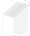
FIG. 1 is a schematic structural diagram of a battery module according to an embodiment of the present disclosure; -
FIG. 2 is a partial schematic diagram of a battery module according to an embodiment of the present disclosure; -
FIG. 3 is a partial exploded view of a battery module according to an embodiment of the present disclosure; -
FIG. 4 is a schematic diagram of connection between a voltage collection sheet and a battery core according to an embodiment of the present disclosure; -
FIG. 5 is a schematic structural diagram of a voltage collection sheet according to an embodiment of the present disclosure; -
FIG. 6 is a schematic structural diagram of a voltage collection sheet from another perspective according to an embodiment of the present disclosure; and -
FIG. 7 is a schematic circuit diagram of a battery module according to an embodiment of the present disclosure. - 1-Voltage collection structure, 2-Battery core, 3-Battery module, 100-Fixed holder, 110-First buckle, 120-Second buckle, 130-Through hole, 140-Third buckle, 200-Circuit board, 300-Voltage collection sheet, 310-Buffer segment, 311-First subsegment, 311a-First end of the first subsegment, 311b-Second end of the first subsegment, 312-Second subsegment, 312a-First end of the second subsegment, 312b-Second end of the second subsegment, 313-Third subsegment, 320-Circuit board connection segment, 330-Battery core connection segment, 400-Conductive housing, 411-First end pole, 412-Second end pole, 420-First connection sheet, 430-Second connection sheet, 440-Positioning groove, and 500-Battery core body.
- Embodiments of the present disclosure are described in detail below, and the embodiments described with reference to the accompanying drawings are exemplary.
- In the description of the present disclosure, it should be understood that orientation or position relationships indicated by the terms such as "center", "longitudinal", "transverse", "length", "width", "thickness", "on", "below", "front", "rear", "left", "right", "vertical", "horizontal", "top", "bottom", "inside", "outside", "clockwise", "counterclockwise", "axial direction", "radial direction", and "circumferential direction" are based on orientation or position relationships shown in the accompanying drawings, and are used only for ease and brevity of illustration and description of the present disclosure, rather than indicating or implying that the mentioned apparatus or component needs to have a particular orientation or needs to be constructed and operated in a particular orientation. Therefore, such terms should not be construed as a limitation to the present disclosure.
- In the description of the present disclosure, "multiple" means two or more.
- In the present disclosure, unless expressly stated and defined otherwise, the term "connection" should be understood in a broad sense. For example, the connection may be a fixed connection, a detachable connection or an integral connection; or may be a mechanical connection or an electrical connection; or may be a direct connection, an indirect connection through an intermediary, or communication between two elements or an interactive relationship between two elements. A person ordinary skill in the art may understand specific meanings of the foregoing terms in the present disclosure according to specific situations.
- The present disclosure aims to resolve at least one of the technical problems existing in the related art. Therefore, the present disclosure provides a voltage collection structure. The voltage collection structure can absorb a height difference between battery cores, and the attachment tightness between a voltage collection sheet and each battery core is improved, so that reliable voltage collection of the battery core can be implemented. The present disclosure further provides a battery module having the voltage collection structure.
- The following describes a
voltage collection structure 1 according to the embodiments of the present disclosure with reference to the accompanying drawings. - As shown in
FIG. 1 to FIG. 6 , thevoltage collection structure 1 includes a fixedholder 100, acircuit board 200, and multiplevoltage collection sheets 300. - The fixed
holder 100 is configured to be connected tomultiple battery cores 2. Thecircuit board 200 is installed on the fixedholder 100. The multiplevoltage collection sheets 300 are installed on thecircuit board 200 and connected to themultiple battery cores 2. At least onevoltage collection sheet 300 includes abuffer segment 310, and at least a portion of thebuffer segment 310 protrudes in a direction that faces away from the battery core 2 (that is, a direction Z shown inFIG. 5 ), so that thevoltage collection sheet 300 has a displacement allowance in a direction that is close to thebattery core 2. A maximum protruding distance of thebuffer segment 310 ranges from 0.5 mm to 20 mm. - It should be noted that the fixed
holder 100 may be an insulating member, for example, made of insulating plastic. - For example, the
voltage collection sheet 300 and thecircuit board 200 may be welded, and thevoltage collection sheet 300 and thebattery core 2 may be welded. - In the
voltage collection structure 1 according to the embodiments of the present disclosure, the fixedholder 100 is connected to themultiple battery cores 2, and thecircuit board 200 is installed on a side of the fixedholder 100 that is away from themultiple battery cores 2, so that the fixedholder 100 can fix a relative position between thecircuit board 200 and themultiple battery cores 2, and avoid contact between thecircuit board 200 and themultiple battery cores 2, thereby avoiding a fault such as a short circuit between thecircuit board 200 and themultiple battery cores 2. - In addition, the multiple
voltage collection sheets 300 are installed on thecircuit board 200 and connected to themultiple battery cores 2. Thevoltage collection sheet 300 may be made of metallic nickel or nickel alloy. Eachvoltage collection sheet 300 collects one of a positive voltage and a negative voltage of abattery core 2 that is connected to the voltage collection sheet. Eachbattery core 2 may be connected to twovoltage collection sheets 300, where the twovoltage collection sheets 300 collect the positive voltage and the negative voltage of thebattery core 2 respectively, to obtain a voltage of thebattery core 2. - In addition, at least one
voltage collection sheet 300 includes abuffer segment 310, and at least a portion of thebuffer segment 310 protrudes in a direction that faces away from thebattery core 2, so that thevoltage collection sheet 300 has a displacement allowance in the direction that is close to thebattery core 2. It should be noted that, eachvoltage collection sheet 300 has thebuffer segment 310 during initial manufacturing. When thevoltage collection structure 1 is connected to themultiple battery cores 2,buffer segments 310 of a part of thevoltage collection sheets 300 may be compressed by an assembly tool (the tool is an abbreviation of a process tool, and an assembly tool refers to an auxiliary device applied to an assembly process of components) to absorb a height difference between themultiple battery cores 2. Therefore, after assembly, thebuffer segments 310 of the part ofvoltage collection sheets 300 may lose a buffering effect. That is, thebuffer segment 310 does not protrude out of thevoltage collection sheet 300 in a direction that faces away from thebattery core 2. - A maximum protruding distance A of the
buffer segment 310 ranges from 0.5 mm to 20 mm. In this way, when a maximum height difference between themultiple battery cores 2 is less than 10 mm, that is, when a height difference between any two of thebattery cores 2 is less than 10 mm, under an action force of the assembly tool, thebuffer segment 310 can be deformed to effectively absorb the height difference between thebattery cores 2. In other words, thevoltage collection sheet 300 is tightly attached to thebattery core 2 to improve a yield of abattery module 3, making voltage collection of themultiple battery cores 2 more reliable. - In this way, the
voltage collection structure 1 according to the embodiments of the present disclosure can absorb the height difference between thebattery cores 2, and the attachment tightness of thevoltage collection sheet 300 and thebattery core 2 is improved, so that reliable voltage collection of thebattery core 2 can be implemented. - According to some specific embodiments of the present disclosure, as shown in
FIG. 5 andFIG. 6 , thevoltage collection sheet 300 further includes a circuitboard connection segment 320 and a batterycore connection segment 330. - The circuit
board connection segment 320 is connected to thecircuit board 200 and an end (that is, afirst end 311a of a first subsegment 311) of thebuffer segment 310, and the batterycore connection segment 330 is connected to thebattery core 2 and another end (that is, afirst end 312a of a second subsegment 312) of thebuffer segment 310. The batterycore connection segment 330 and the circuitboard connection segment 320 are parallel and located in different planes. A portion of thebuffer segment 310 is located on a side of the circuitboard connection segment 320 that faces away from the batterycore connection segment 330 in a thickness direction (that is, the direction Z shown inFIG. 5 ) of thevoltage collection sheet 300, so that the batterycore connection segment 330 has a displacement allowance in the direction that is close to thebattery core 2. A maximum distance A between the portion of thebuffer segment 310 and the circuitboard connection segment 320 in the thickness direction of thevoltage collection sheet 300 ranges from 0.5 mm to 20 mm. - For example, the circuit
board connection segment 320 may be connected to a side of thecircuit board 200 that faces the fixedholder 100. A side surface of thebuffer segment 310 that is away from thebattery core 2 is flush with a side surface of thecircuit board 200 that faces away from the fixedholder 100. Thebuffer segment 310 is attached to an outer peripheral surface of thecircuit board 200, so that a relative position between thecircuit board 200 and thevoltage collection sheet 300 becomes more stable. In addition, a connection area between the circuitboard connection segment 320 and thecircuit board 200 is larger, and a connection area between the batterycore connection segment 330 and thebattery core 2 is larger, which is beneficial for welding. - In addition, the
buffer segment 310 may pass through the fixedholder 100 along a thickness direction of the fixedholder 100 to be connected to the batterycore connection segment 330. In this way, thevoltage collection sheet 300 presents a shape similar to "n". Because the foregoing portion (for example, athird subsegment 313 shown inFIG. 6 ) of thebuffer segment 310 is farthest away from thebattery core 2 in the thickness direction of thevoltage collection sheet 300, when the assembly tool moves towards the direction that is close to thebattery core 2, the assembly tool first comes in contact with thebuffer segment 310, so that thebuffer segment 310 is deformed earlier than the circuitboard connection segment 320. Therefore, while the attachment tightness between the batterycore connection segment 330 and thebattery core 2 is ensured, detachment between the circuitboard connection segment 320 and thecircuit board 200 can be avoided. In addition, it should be noted that, in the present disclosure, thickness directions of the fixedholder 100, thecircuit board 200, and thevoltage collection sheet 300 are consistent, for example, the direction Z shown inFIG. 5 , or a direction that is opposite to the direction Z. - Further, a dimension C of the portion of the
buffer segment 310 in a width direction of thevoltage collection sheet 300 ranges from 2 mm to 20 mm. In this way, a sufficiently high structure strength of thebuffer segment 310 may be ensured, and a width of thevoltage collection sheet 300 may be prevented from being excessively large and occupying too much space, which is beneficial for reducing a volume of thevoltage collection structure 1. In addition, a dimension B of the portion of thebuffer segment 310 in an extension direction of thevoltage collection sheet 300 ranges from 0.5 mm to 20 mm. In this way, a deformation dimension of thebuffer segment 310 is sufficient. This can ensure that after thebuffer segment 310 is deformed, thevoltage collection sheet 300 is effectively attached to thebattery core 2. It should be noted that, in the present disclosure, the thickness direction of thevoltage collection sheet 300, the width direction of thevoltage collection sheet 300, and the extension direction of thevoltage collection sheet 300 are perpendicular to each other in space. For example, "the thickness direction of thevoltage collection sheet 300" is a Z-axis direction of a spatial coordinate system, "the width direction of thevoltage collection sheet 300" is a Y-axis direction of the spatial coordinate system, and "the extension direction of thevoltage collection sheet 300" are an X-axis direction of the spatial coordinate direction. - In some embodiments of the present disclosure, as shown in
FIG. 5 andFIG. 6 , thebuffer segment 310 includes thefirst subsegment 311, thesecond subsegment 312, and thethird subsegment 313. - The
first end 311a of thefirst subsegment 311 is connected to an end of the circuitboard connection segment 320 that is adjacent to the batterycore connection segments 330, and thefirst subsegment 311 extends in a direction that is away from the batterycore connection segment 330 in a thickness direction of the circuitboard connection segment 320. Thefirst end 312a of thesecond subsegment 312 is connected to an end of the batterycore connection segment 330 that is adjacent to the circuitboard connection segment 320, and thesecond subsegment 312 extends in a direction towards the circuitboard connection segment 320 in a thickness direction of the batterycore connection segment 330 to a side of the circuitboard connection segment 320 that faces away from the batterycore connection segment 330. Two ends of thethird subsegment 313 are respectively connected to asecond end 311b of thefirst subsegment 311 and asecond end 312b of thesecond subsegment 312. It should be noted that, in the present disclosure, the thickness direction of the circuitboard connection segment 320, the thickness direction of the batterycore connection segment 330, and the thickness direction of thevoltage collection sheet 300 are consistent. - In the present disclosure, that at least a portion of the
buffer segment 310 protrudes in a direction that faces away from thebattery core 2 may be: a portion of thebuffer segment 310 protrudes in the direction that faces away from thebattery core 2, or thewhole buffer segment 310 protrudes in the direction that faces away from thebattery core 2, to form a protrusion. For example, a portion (that is, the third subsegment 313) of thebuffer segment 310 protrudes in the direction that faces away from thebattery core 2. Thefirst subsegment 311 and the circuitboard connection segment 320 may be in arc-shaped transition, and thesecond subsegment 312 and the batterycore connection segment 330 may be in arc-shaped transition. These two arc-shaped transitions may be respectively located at thefirst subsegment 311 and thesecond subsegment 312. In the present disclosure, a location of the arc-shaped transition is not limited, provided that a protrusion can be formed to allow thevoltage collection sheet 300 to have a displacement allowance in the direction that is close to thebattery core 2. The two ends of thethird subsegment 313 may be in arc-shaped transition with thefirst subsegment 311 and thesecond subsegment 312 respectively. In other words, thethird subsegment 313 is bent and connected to thefirst subsegment 311 and thesecond subsegment 312 respectively. In this way, stress concentration in thebuffer segment 310 itself and between thebuffer segment 310 and the circuitboard connection segment 320 as well as the batterycore connection segment 330 can be avoided, and stress distribution is more even. - In this way, a connection between the
buffer segment 310 and the circuitboard connection segment 320 as well as the batterycore connection segment 330 can be ensured, and thebuffer segment 310 is formed by three segments, so that an acute angle in thebuffer segment 310 itself and junctions of thebuffer segment 310 and the circuitboard connection segment 320 as well as the batterycore connection segment 330 can be avoided, and a structure of thevoltage collection sheet 300 becomes more reliable. - Optionally, the
third subsegment 313, the batterycore connection segment 330, and the circuitboard connection segment 320 are parallel. In this way, when the assembly tool compresses thebuffer segment 310 downwards, the assembly tool first comes in contact with thethird subsegment 313. In that case, the assembly tool is in surface contact with thethird subsegment 313, a contact area is larger, thereby preventing thebuffer segment 310 from being damaged due to excessively large local pressure on thebuffer segment 310. In addition, thefirst subsegment 311 and thesecond subsegment 312 are parallel to each other, and thefirst subsegment 311 and thesecond subsegment 312 are both perpendicular to thethird subsegment 313. This can avoid occurrence of an acute angle at a transition of thebuffer segment 310 and also help reduce a dimension of thevoltage collection sheet 300 in the extension direction thereof, thereby facilitating installation of thevoltage collection structure 1. - According to some specific embodiments of the present disclosure, as shown in
FIG. 2 andFIG. 3 , afirst buckle 110 and asecond buckle 120 are arranged on a side of the fixedholder 100 that faces away from thebattery core 2. Thefirst buckle 110 is configured to be clamped onto a side of thecircuit board 200 that faces away from thebattery core 2. Multiple throughholes 130 are provided on the fixedholder 100 along a thickness direction thereof. Poles of themultiple battery cores 2 are respectively inserted into the multiple through holes 130 (for example, afirst end pole 411 or asecond end pole 412 of abattery core body 500 is inserted into a corresponding through hole 130), and an outer peripheral surface of a portion of each pole that passes through the throughhole 130 is clamped by thesecond buckle 120. - In this way, the fixed
holder 100 is fixed to thecircuit board 200 and thebattery core 2 respectively in a clamping manner. This facilitates disassembly and assembly between thecircuit board 200 and the fixedholder 100, as well as disassembly and assembly between the fixedholder 100 and thebattery core 2. In addition, thefirst buckle 110 and thesecond buckle 120 may be made of a rubber material. That is, thefirst buckle 110 and thesecond buckle 120 have elasticity. Thefirst buckle 110 and thesecond buckle 120 can undergo elastic deformation, further improving the convenience of disassembly and assembly. - The following describes a battery module 3 (for example, a power battery) according to the embodiments of the present disclosure with reference to the accompanying drawings. As shown in
FIG. 1 to FIG. 4 , thebattery module 3 includesmultiple battery cores 2 and thevoltage collection structure 1 according to the foregoing embodiments of the present disclosure. - The
battery module 3 according to the embodiments of the present disclosure has advantages such as reliable voltage collection by utilizing thevoltage collection structure 1 according to the foregoing embodiments of the present disclosure. - According to some specific embodiments of the present disclosure, as shown in
FIG. 1 to FIG. 4 , eachbattery core 2 includes aconductive housing 400 and abattery core body 500 that is arranged in theconductive housing 400. Thebattery core 2 has a first end and second end that are opposite to each other. The battery core body has afirst end pole 411 that is arranged on the first end and asecond end pole 412 that is arranged on the second end, and thefirst end pole 411 is connected to theconductive housing 400. When thefirst end pole 411 of the battery core body is a negative pole, thesecond end pole 412 is a positive pole; and on the contrary, when thefirst end pole 411 of the battery core body is a positive pole, thesecond end pole 412 is a negative pole. In addition, thevoltage collection structure 1 is arranged on the second end, a part of the multiplevoltage collection sheets 300 are connected to thesecond end poles 412, and another part of the multiplevoltage collection sheets 300 are connected to theconductive housings 400. - In this way, a positive voltage and a negative voltage of
battery core 2 can be collected simultaneously by only installing thevoltage collection structure 1 on a side of thebattery core 2. A structure of thebattery module 3 is simpler, and the multiplevoltage collection sheets 300 may be arranged on two opposite sides ofcircuit board 200. For example, the multiplevoltage collection sheets 300 are arranged on two sides of a width direction ofcircuit board 200. Thevoltage collection sheets 300 on one side of the two sides of the width direction ofcircuit board 200 are connected to thesecond end poles 412, and thevoltage collection sheets 300 on the other side of the two sides of the width direction ofcircuit board 200 are connected to theconductive housings 400, making voltage collection more accurate. - Further, as shown in
FIG. 3 andFIG. 7 , thebattery module 3 further includes afirst connection sheet 420 and asecond connection sheet 430. - The
multiple battery cores 2 are arranged along a thickness direction of thebattery cores 2, and polarities offirst end poles 411 ofadjacent battery cores 2 are opposite and polarities ofsecond end poles 412 thereof are opposite. Eachfirst connection sheet 420 connectsfirst end poles 411 ofadjacent battery cores 2, and eachsecond connection sheets 430 connectssecond end poles 412 ofadjacent battery cores 2, so that themultiple battery cores 2 are connected in series. Thesecond connection sheet 430 is located between the fixedholder 100 and thecircuit board 200, and a part of the multiplevoltage collection sheets 300 are connected to thesecond end poles 412 through thesecond connection sheet 430. - For example, a
third buckle 140 is arranged on a side of the fixedholder 100 that faces away from thebattery core 2, where thethird buckle 140 is configured to be clamped to thesecond connection sheet 430, and thesecond connection sheet 430 may be located between the fixedholder 100 of thecircuit board 200. - In this way, a voltage of each
battery core 2 can be detected through thevoltage collection structure 1. This is beneficial for ensuring reliable operation of themultiple battery cores 2, thereby ensuring reliable operation of thebattery module 3. - Optionally, as shown in
FIG. 3 ,multiple positioning grooves 440 are provided on the side of the fixedholder 100 that faces away from thebattery core 2. Thesecond end pole 412 passes through a bottom of thepositioning groove 440. A portion of thesecond connection sheet 430 is located in thepositioning groove 440 and connected to thesecond end pole 412. The throughhole 130 is constructed at the bottom of thepositioning groove 440. In this way, a relative position between thesecond connection sheet 430 and the fixedholder 100 is more reliable, so that the electrical connection reliability between thesecond connection sheet 430 and thesecond end pole 412 can be ensured. - Other components and operations of the
voltage collection structure 1 according to the embodiments of the present disclosure and thebattery module 3 having the voltage collection structure are known to a person of ordinary skill in the art, and are not described herein in detail. - In the description of this specification, the description of the reference terms such as "an embodiment", "some embodiments", "exemplary embodiments", "an example", "a specific example", or "some examples" means that the specific features, structures, materials or characteristics described with reference to the embodiment or example are included in at least one embodiment or example of the present disclosure. In this specification, schematic description of the foregoing terms does not necessarily refer to the same embodiment or example.
- Although the embodiments of the present disclosure have been shown and described, a person of ordinary skill in the art may understand that various changes, modifications, replacements and variations may be made to the embodiments without departing from the principle and spirit of the present disclosure, and the scope of the present disclosure is defined by the claims and equivalents thereof.
Claims (11)
- A voltage collection structure (1), comprising:a fixed holder (100), the fixed holder being configured to be connected to a plurality of battery cores (2);a circuit board (200), the circuit board being installed on a side of the fixed holder that is away from the plurality of battery cores; anda plurality of voltage collection sheets (300), the plurality of voltage collection sheets being installed on the circuit board and connected to the plurality of battery cores, each voltage collection sheet comprising a buffer segment (310), and at least a portion of the buffer segment protruding in a direction that faces away from the battery core, causing the voltage collection sheet to have a displacement allowance in a direction that is close to the battery core, wherein a maximum protruding distance of the buffer segment ranges from 0.5 mm to 20 mm.
- The voltage collection structure according to claim 1, wherein a dimension of the at least portion of the buffer segment in a width direction of the voltage collection sheet ranges from 2 mm to 20 mm, and a dimension in an extension direction of the voltage collection sheet ranges from 0.5 mm to 20 mm.
- The voltage collection structure according to claim 1, wherein each of the plurality of voltage collection sheets further comprises:a circuit board connection segment (320), the circuit board connection segment being connected to the circuit board and an end of the buffer segment, anda battery core connection segment (330), the battery core connection segment being configured to be connected to the battery core and another end of the buffer segment, the battery core connection segment and the circuit board connection segment being parallel and located in different planes, and a portion of the buffer segment being located on a side of the circuit board connection segment that faces away from the battery core connection segment in a thickness direction of the voltage collection sheet, causing the battery core connection segment to have a displacement allowance in the direction that is close to the battery core, wherein a maximum distance between the portion of the buffer segment and the circuit board connection segment in the thickness direction of the voltage collection sheet ranges from 0.5 mm to 20 mm.
- The voltage collection structure according to claim 3, wherein the buffer segment comprises:a first subsegment (311), wherein a first end (311a) of the first subsegment is connected to an end of the circuit board connection segment that is adjacent to the battery core connection segment, and the first subsegment extends in a direction away from the battery core connection segment in a thickness direction of the circuit board connection segment;a second subsegment (312), wherein a first end (312a) of the second subsegment is connected to an end of the battery core connection segment that is adjacent to the circuit board connection segment, and the second subsegment extends in a direction close to the circuit board connection segment in a thickness direction of the battery core connection segment; anda third subsegment (313), wherein two ends of the third subsegment are connected to a second end (311b) of the first subsegment and a second end (312b) of the second subsegment respectively.
- The voltage collection structure according to claim 4, wherein the first subsegment and the second subsegment are parallel and perpendicular to the third subsegment, and the third subsegment, the battery core connection segment, and the circuit board connection segment are parallel.
- The voltage collection structure according to claim 4, wherein the third subsegment is bent and connected to the first subsegment and the second subsegment respectively.
- The voltage collection structure according to claim 1, wherein a first buckle (110) and a second buckle (120) are arranged on a side of the fixed holder that faces away from the battery core, and the first buckle is configured to be clamped onto a side of the circuit board that faces away from the battery core; and
a plurality of through holes (130) are provided on the fixed holder along a thickness direction thereof, poles of the plurality of battery cores are respectively inserted into the plurality of through holes, and a portion of each pole that passes through the through hole is clamped by the second buckle. - A battery module (3), comprising:a plurality of battery cores (2); andthe voltage collection structure (1) according to any one of claims 1 to 7.
- The battery module according to claim 8, wherein each battery core comprises a conductive housing (400) and a battery core body (500) that is arranged in the conductive housing, the battery core has a first end and second end that are opposite to each other, the battery core body has a first end pole (411) that is arranged on the first end and a second end pole (412) that is arranged on the second end, and the first end pole is connected to the conductive housing; and
the voltage collection structure is arranged on the second end, a part of the plurality of voltage collection sheets are connected to the second end poles, and another part of the plurality of voltage collection sheets are connected to the conductive housings. - The battery module according to claim 9, further comprising:at least one first connection sheet (420), each first connection sheet connecting first end poles of two adjacent battery cores, wherein the plurality of battery cores are arranged along a thickness direction of the battery cores, and polarities of first end poles of adjacent battery cores are opposite and polarities of second end poles thereof are opposite; andat least one second connection sheet (430), each second connection sheet connecting second end poles of two adjacent battery cores, and the plurality of battery cores being connected in series through the at least one first connection sheet and the at least one second connection sheet, wherein the second connection sheet is located between the fixed holder and the circuit board, and the part of the plurality of voltage collection sheets are connected to the second end poles through the second connection sheet.
- The battery module according to claim 10, wherein a plurality of positioning grooves (440) are provided on a side of the fixed holder that faces away from the battery core, the second end pole passes through the positioning groove, and a portion of the second connection sheet is located in the positioning groove and connected to the second end pole.
Applications Claiming Priority (2)
| Application Number | Priority Date | Filing Date | Title |
|---|---|---|---|
| CN202123317998.2U CN217387271U (en) | 2021-12-27 | 2021-12-27 | Voltage acquisition structure and battery module with same |
| PCT/CN2022/133368 WO2023124652A1 (en) | 2021-12-27 | 2022-11-22 | Voltage acquisition structure, and battery module having voltage acquisition structure |
Publications (2)
| Publication Number | Publication Date |
|---|---|
| EP4395001A1 true EP4395001A1 (en) | 2024-07-03 |
| EP4395001A4 EP4395001A4 (en) | 2025-04-23 |
Family
ID=83093797
Family Applications (1)
| Application Number | Title | Priority Date | Filing Date |
|---|---|---|---|
| EP22913910.0A Pending EP4395001A4 (en) | 2021-12-27 | 2022-11-22 | VOLTAGE ACQUISITION STRUCTURE AND BATTERY MODULE COMPRISING A VOLTAGE ACQUISITION STRUCTURE |
Country Status (8)
| Country | Link |
|---|---|
| US (1) | US20240243375A1 (en) |
| EP (1) | EP4395001A4 (en) |
| JP (1) | JP7820506B2 (en) |
| KR (1) | KR20240046779A (en) |
| CN (1) | CN217387271U (en) |
| AU (1) | AU2022428445B2 (en) |
| CA (1) | CA3233042A1 (en) |
| WO (1) | WO2023124652A1 (en) |
Families Citing this family (2)
| Publication number | Priority date | Publication date | Assignee | Title |
|---|---|---|---|---|
| CN217387271U (en) * | 2021-12-27 | 2022-09-06 | 比亚迪股份有限公司 | Voltage acquisition structure and battery module with same |
| CN119786852B (en) * | 2024-09-25 | 2025-10-31 | 比亚迪股份有限公司 | Battery packs, battery pack manufacturing methods, and electrical devices. |
Family Cites Families (12)
| Publication number | Priority date | Publication date | Assignee | Title |
|---|---|---|---|---|
| JP6164489B2 (en) * | 2014-01-21 | 2017-07-19 | 株式会社オートネットワーク技術研究所 | Wiring module |
| KR102332338B1 (en) * | 2017-06-01 | 2021-11-29 | 삼성에스디아이 주식회사 | Battery pack |
| JP2019053928A (en) * | 2017-09-15 | 2019-04-04 | 株式会社東芝 | Assembled battery |
| CN209217091U (en) * | 2018-12-07 | 2019-08-06 | 北京国能电池科技股份有限公司 | Voltage acquisition component and battery modules |
| CN210136942U (en) * | 2019-08-05 | 2020-03-10 | 宁德时代新能源科技股份有限公司 | battery module |
| CN210136984U (en) * | 2019-08-29 | 2020-03-10 | 宁德时代新能源科技股份有限公司 | Battery module |
| CN210123777U (en) * | 2019-08-30 | 2020-03-03 | 蜂巢能源科技有限公司 | Battery sampling module and battery module |
| CN112582759B (en) * | 2019-09-30 | 2022-05-13 | 比亚迪股份有限公司 | Battery module and electric automobile |
| KR102925430B1 (en) * | 2019-12-03 | 2026-02-11 | 삼성전자주식회사 | Battery system |
| CN211320199U (en) * | 2019-12-31 | 2020-08-21 | 宁德时代新能源科技股份有限公司 | Sampling assembly, battery module, battery pack and device |
| CN217387271U (en) * | 2021-12-27 | 2022-09-06 | 比亚迪股份有限公司 | Voltage acquisition structure and battery module with same |
| CN217507605U (en) * | 2022-06-15 | 2022-09-27 | 浙江极氪智能科技有限公司 | Sampling connection piece, battery module and vehicle |
-
2021
- 2021-12-27 CN CN202123317998.2U patent/CN217387271U/en active Active
-
2022
- 2022-11-22 AU AU2022428445A patent/AU2022428445B2/en active Active
- 2022-11-22 CA CA3233042A patent/CA3233042A1/en active Pending
- 2022-11-22 JP JP2024519497A patent/JP7820506B2/en active Active
- 2022-11-22 KR KR1020247009392A patent/KR20240046779A/en active Pending
- 2022-11-22 WO PCT/CN2022/133368 patent/WO2023124652A1/en not_active Ceased
- 2022-11-22 EP EP22913910.0A patent/EP4395001A4/en active Pending
-
2024
- 2024-03-30 US US18/622,934 patent/US20240243375A1/en active Pending
Also Published As
| Publication number | Publication date |
|---|---|
| JP7820506B2 (en) | 2026-02-25 |
| CA3233042A1 (en) | 2023-07-06 |
| KR20240046779A (en) | 2024-04-09 |
| EP4395001A4 (en) | 2025-04-23 |
| AU2022428445A1 (en) | 2024-04-04 |
| AU2022428445B2 (en) | 2025-12-18 |
| JP2024543307A (en) | 2024-11-21 |
| US20240243375A1 (en) | 2024-07-18 |
| CN217387271U (en) | 2022-09-06 |
| WO2023124652A1 (en) | 2023-07-06 |
Similar Documents
| Publication | Publication Date | Title |
|---|---|---|
| US20240243375A1 (en) | Voltage acquisition structure, and battery module having voltage acquisition structure | |
| US20210066700A1 (en) | Single-cell battery, battery module, power battery and electric vehicle | |
| CN115939611B (en) | End cover assembly, energy storage device and electric equipment | |
| CN113745566B (en) | Fuel cell metal bipolar plate inspection auxiliary structure and fuel cell | |
| CN110323463A (en) | Fuel cell bipolar plate and fuel cell voltage inspection plug-in unit | |
| EP4439834A1 (en) | Battery tray assembly, battery pack, and vehicle | |
| CN211980682U (en) | End plate assembly and battery module | |
| CN217768674U (en) | Battery transfer structure, battery connection structure, battery module and battery | |
| CN222840020U (en) | Photovoltaic module | |
| CN209496940U (en) | A battery module | |
| US20240396180A1 (en) | Current collector | |
| EP4366162B1 (en) | Junction box and method for mounting a junction box | |
| CN217336031U (en) | Lithium battery flexible circuit board structure | |
| CN115133233B (en) | Battery core pole column, battery core and battery module | |
| CN112928377B (en) | Integrated cover plate and power battery module | |
| CN213782208U (en) | Battery and battery module with same | |
| CN210668518U (en) | A battery module and an electric vehicle | |
| CN221486571U (en) | Clamping device | |
| CN223079302U (en) | Connection assembly and battery | |
| CN221353127U (en) | Output pole base, battery module and vehicle | |
| CN224217470U (en) | Battery cell | |
| CN222214414U (en) | Dual-cell battery and electronic equipment | |
| CN220491940U (en) | Split type battery buffer shell | |
| CN220233393U (en) | A conductive sheet installation component, battery core module and energy storage power supply | |
| CN219475991U (en) | Chip assembly and developing box |
Legal Events
| Date | Code | Title | Description |
|---|---|---|---|
| STAA | Information on the status of an ep patent application or granted ep patent |
Free format text: STATUS: THE INTERNATIONAL PUBLICATION HAS BEEN MADE |
|
| PUAI | Public reference made under article 153(3) epc to a published international application that has entered the european phase |
Free format text: ORIGINAL CODE: 0009012 |
|
| STAA | Information on the status of an ep patent application or granted ep patent |
Free format text: STATUS: REQUEST FOR EXAMINATION WAS MADE |
|
| 17P | Request for examination filed |
Effective date: 20240325 |
|
| AK | Designated contracting states |
Kind code of ref document: A1 Designated state(s): AL AT BE BG CH CY CZ DE DK EE ES FI FR GB GR HR HU IE IS IT LI LT LU LV MC ME MK MT NL NO PL PT RO RS SE SI SK SM TR |
|
| REG | Reference to a national code |
Ref country code: DE Ref legal event code: R079 Free format text: PREVIOUS MAIN CLASS: H01M0010480000 Ipc: H01M0050507000 |
|
| DAV | Request for validation of the european patent (deleted) | ||
| DAX | Request for extension of the european patent (deleted) | ||
| A4 | Supplementary search report drawn up and despatched |
Effective date: 20250321 |
|
| RIC1 | Information provided on ipc code assigned before grant |
Ipc: H01M 50/209 20210101ALN20250317BHEP Ipc: H01M 50/548 20210101ALI20250317BHEP Ipc: H01M 50/289 20210101ALI20250317BHEP Ipc: H01M 10/42 20060101ALI20250317BHEP Ipc: H01M 50/284 20210101ALI20250317BHEP Ipc: H01M 50/569 20210101ALI20250317BHEP Ipc: H01M 50/503 20210101ALI20250317BHEP Ipc: H01M 50/507 20210101AFI20250317BHEP |