EP4394994A1 - Battery cell, battery and electrical device - Google Patents
Battery cell, battery and electrical device Download PDFInfo
- Publication number
- EP4394994A1 EP4394994A1 EP21957000.9A EP21957000A EP4394994A1 EP 4394994 A1 EP4394994 A1 EP 4394994A1 EP 21957000 A EP21957000 A EP 21957000A EP 4394994 A1 EP4394994 A1 EP 4394994A1
- Authority
- EP
- European Patent Office
- Prior art keywords
- positive electrode
- battery cell
- electrode plate
- current collector
- negative electrode
- Prior art date
- Legal status (The legal status is an assumption and is not a legal conclusion. Google has not performed a legal analysis and makes no representation as to the accuracy of the status listed.)
- Pending
Links
Images


Classifications
-
- H—ELECTRICITY
- H01—ELECTRIC ELEMENTS
- H01M—PROCESSES OR MEANS, e.g. BATTERIES, FOR THE DIRECT CONVERSION OF CHEMICAL ENERGY INTO ELECTRICAL ENERGY
- H01M10/00—Secondary cells; Manufacture thereof
- H01M10/04—Construction or manufacture in general
- H01M10/0431—Cells with wound or folded electrodes
-
- H—ELECTRICITY
- H01—ELECTRIC ELEMENTS
- H01M—PROCESSES OR MEANS, e.g. BATTERIES, FOR THE DIRECT CONVERSION OF CHEMICAL ENERGY INTO ELECTRICAL ENERGY
- H01M10/00—Secondary cells; Manufacture thereof
- H01M10/04—Construction or manufacture in general
- H01M10/049—Processes for forming or storing electrodes in the battery container
-
- H—ELECTRICITY
- H01—ELECTRIC ELEMENTS
- H01M—PROCESSES OR MEANS, e.g. BATTERIES, FOR THE DIRECT CONVERSION OF CHEMICAL ENERGY INTO ELECTRICAL ENERGY
- H01M50/00—Constructional details or processes of manufacture of the non-active parts of electrochemical cells other than fuel cells, e.g. hybrid cells
- H01M50/50—Current conducting connections for cells or batteries
- H01M50/502—Interconnectors for connecting terminals of adjacent batteries; Interconnectors for connecting cells outside a battery casing
-
- H—ELECTRICITY
- H01—ELECTRIC ELEMENTS
- H01M—PROCESSES OR MEANS, e.g. BATTERIES, FOR THE DIRECT CONVERSION OF CHEMICAL ENERGY INTO ELECTRICAL ENERGY
- H01M10/00—Secondary cells; Manufacture thereof
- H01M10/05—Accumulators with non-aqueous electrolyte
- H01M10/058—Construction or manufacture
- H01M10/0587—Construction or manufacture of accumulators having only wound construction elements, i.e. wound positive electrodes, wound negative electrodes and wound separators
-
- H—ELECTRICITY
- H01—ELECTRIC ELEMENTS
- H01M—PROCESSES OR MEANS, e.g. BATTERIES, FOR THE DIRECT CONVERSION OF CHEMICAL ENERGY INTO ELECTRICAL ENERGY
- H01M50/00—Constructional details or processes of manufacture of the non-active parts of electrochemical cells other than fuel cells, e.g. hybrid cells
- H01M50/10—Primary casings; Jackets or wrappings
- H01M50/102—Primary casings; Jackets or wrappings characterised by their shape or physical structure
- H01M50/105—Pouches or flexible bags
-
- H—ELECTRICITY
- H01—ELECTRIC ELEMENTS
- H01M—PROCESSES OR MEANS, e.g. BATTERIES, FOR THE DIRECT CONVERSION OF CHEMICAL ENERGY INTO ELECTRICAL ENERGY
- H01M50/00—Constructional details or processes of manufacture of the non-active parts of electrochemical cells other than fuel cells, e.g. hybrid cells
- H01M50/10—Primary casings; Jackets or wrappings
- H01M50/116—Primary casings; Jackets or wrappings characterised by the material
- H01M50/117—Inorganic material
- H01M50/119—Metals
-
- H—ELECTRICITY
- H01—ELECTRIC ELEMENTS
- H01M—PROCESSES OR MEANS, e.g. BATTERIES, FOR THE DIRECT CONVERSION OF CHEMICAL ENERGY INTO ELECTRICAL ENERGY
- H01M50/00—Constructional details or processes of manufacture of the non-active parts of electrochemical cells other than fuel cells, e.g. hybrid cells
- H01M50/10—Primary casings; Jackets or wrappings
- H01M50/116—Primary casings; Jackets or wrappings characterised by the material
- H01M50/121—Organic material
-
- H—ELECTRICITY
- H01—ELECTRIC ELEMENTS
- H01M—PROCESSES OR MEANS, e.g. BATTERIES, FOR THE DIRECT CONVERSION OF CHEMICAL ENERGY INTO ELECTRICAL ENERGY
- H01M50/00—Constructional details or processes of manufacture of the non-active parts of electrochemical cells other than fuel cells, e.g. hybrid cells
- H01M50/10—Primary casings; Jackets or wrappings
- H01M50/116—Primary casings; Jackets or wrappings characterised by the material
- H01M50/124—Primary casings; Jackets or wrappings characterised by the material having a layered structure
- H01M50/126—Primary casings; Jackets or wrappings characterised by the material having a layered structure comprising three or more layers
- H01M50/129—Primary casings; Jackets or wrappings characterised by the material having a layered structure comprising three or more layers with two or more layers of only organic material
-
- H—ELECTRICITY
- H01—ELECTRIC ELEMENTS
- H01M—PROCESSES OR MEANS, e.g. BATTERIES, FOR THE DIRECT CONVERSION OF CHEMICAL ENERGY INTO ELECTRICAL ENERGY
- H01M50/00—Constructional details or processes of manufacture of the non-active parts of electrochemical cells other than fuel cells, e.g. hybrid cells
- H01M50/10—Primary casings; Jackets or wrappings
- H01M50/172—Arrangements of electric connectors penetrating the casing
- H01M50/174—Arrangements of electric connectors penetrating the casing adapted for the shape of the cells
- H01M50/178—Arrangements of electric connectors penetrating the casing adapted for the shape of the cells for pouch or flexible bag cells
-
- H—ELECTRICITY
- H01—ELECTRIC ELEMENTS
- H01M—PROCESSES OR MEANS, e.g. BATTERIES, FOR THE DIRECT CONVERSION OF CHEMICAL ENERGY INTO ELECTRICAL ENERGY
- H01M50/00—Constructional details or processes of manufacture of the non-active parts of electrochemical cells other than fuel cells, e.g. hybrid cells
- H01M50/10—Primary casings; Jackets or wrappings
- H01M50/183—Sealing members
- H01M50/186—Sealing members characterised by the disposition of the sealing members
- H01M50/188—Sealing members characterised by the disposition of the sealing members the sealing members being arranged between the lid and terminal
-
- H—ELECTRICITY
- H01—ELECTRIC ELEMENTS
- H01M—PROCESSES OR MEANS, e.g. BATTERIES, FOR THE DIRECT CONVERSION OF CHEMICAL ENERGY INTO ELECTRICAL ENERGY
- H01M50/00—Constructional details or processes of manufacture of the non-active parts of electrochemical cells other than fuel cells, e.g. hybrid cells
- H01M50/30—Arrangements for facilitating escape of gases
- H01M50/342—Non-re-sealable arrangements
- H01M50/3425—Non-re-sealable arrangements in the form of rupturable membranes or weakened parts, e.g. pierced with the aid of a sharp member
-
- H—ELECTRICITY
- H01—ELECTRIC ELEMENTS
- H01M—PROCESSES OR MEANS, e.g. BATTERIES, FOR THE DIRECT CONVERSION OF CHEMICAL ENERGY INTO ELECTRICAL ENERGY
- H01M50/00—Constructional details or processes of manufacture of the non-active parts of electrochemical cells other than fuel cells, e.g. hybrid cells
- H01M50/50—Current conducting connections for cells or batteries
- H01M50/531—Electrode connections inside a battery casing
- H01M50/538—Connection of several leads or tabs of wound or folded electrode stacks
-
- Y—GENERAL TAGGING OF NEW TECHNOLOGICAL DEVELOPMENTS; GENERAL TAGGING OF CROSS-SECTIONAL TECHNOLOGIES SPANNING OVER SEVERAL SECTIONS OF THE IPC; TECHNICAL SUBJECTS COVERED BY FORMER USPC CROSS-REFERENCE ART COLLECTIONS [XRACs] AND DIGESTS
- Y02—TECHNOLOGIES OR APPLICATIONS FOR MITIGATION OR ADAPTATION AGAINST CLIMATE CHANGE
- Y02E—REDUCTION OF GREENHOUSE GAS [GHG] EMISSIONS, RELATED TO ENERGY GENERATION, TRANSMISSION OR DISTRIBUTION
- Y02E60/00—Enabling technologies; Technologies with a potential or indirect contribution to GHG emissions mitigation
- Y02E60/10—Energy storage using batteries
-
- Y—GENERAL TAGGING OF NEW TECHNOLOGICAL DEVELOPMENTS; GENERAL TAGGING OF CROSS-SECTIONAL TECHNOLOGIES SPANNING OVER SEVERAL SECTIONS OF THE IPC; TECHNICAL SUBJECTS COVERED BY FORMER USPC CROSS-REFERENCE ART COLLECTIONS [XRACs] AND DIGESTS
- Y02—TECHNOLOGIES OR APPLICATIONS FOR MITIGATION OR ADAPTATION AGAINST CLIMATE CHANGE
- Y02P—CLIMATE CHANGE MITIGATION TECHNOLOGIES IN THE PRODUCTION OR PROCESSING OF GOODS
- Y02P70/00—Climate change mitigation technologies in the production process for final industrial or consumer products
- Y02P70/50—Manufacturing or production processes characterised by the final manufactured product
Definitions
- This embodiment of this application includes the following technical effect:
- a short circuit preferentially occurs to the positive electrode plate and the negative electrode plate in the outermost electrode plate.
- a short circuit occurs to the positive electrode plate or the negative electrode plate in the outermost electrode plate and to a metal layer in the packaging bag, and the short-circuit position is in the outermost electrode plate of the battery cell rather than in the battery cell. This facilitates heat dissipation and avoids combustion or explosion of the battery cell, thus improving the safety of the battery cell.
- the present invention reduces the use of a layer of bare foil region while improving the safety of the battery cell, thus increasing the energy density of the battery cell.
- the electrode assembly in a thickness direction of the electrode assembly, includes a first main plane and a second main plane disposed opposite each other, the outermost positive electrode plate includes a first terminating end, the first terminating end is disposed on the first main plane, the outermost negative electrode plate includes a second terminating end, and the second terminating end is disposed on the second main plane.
- the battery cell further includes a positive electrode tab disposed on the positive electrode plate.
- the packaging bag includes a fusion layer, a metal layer, and a protective layer stacked sequentially.
- the fusion layer is disposed on an inner side surface of the metal layer and configured to be melted by heat to seal the packaging bag
- the protective layer is disposed on an outer side surface of the metal layer.
- the packaging bag is provided with a sealing portion, and the positive electrode tab is electrically connected to the metal layer and extends from the sealing portion.
- the fusion layer and the sealing portion improve the sealing performance of the packaging bag.
- the protective layer increases the structural strength of the packaging bag.
- the fusion layer in the sealing portion is provided with a through hole, and the positive electrode tab is electrically connected to the metal layer via the through hole.
- the battery cell further includes a tab adhesive layer for the positive electrode tab to penetrate through, and the tab adhesive layer is partially disposed in the sealing portion.
- the through hole improves the convenience of connection between the positive electrode tab and the metal layer.
- the tab adhesive layer is melted and combined with the fusion layer, which improves the sealing performance of the packaging bag.
- the tab adhesive layer is a conductive adhesive layer, and a portion of the tab adhesive layer corresponding to the through hole runs through the through hole and abuts against the metal layer to be electrically connected to the metal layer.
- the tab adhesive layer being melted and combined with the fusion layer improves the air tightness of the battery cell.
- the tab adhesive layer made of a conductive adhesive enables the positive electrode tab to be electrically connected to the metal layer, allowing the short circuit to preferentially occur to the metal layer and the positive electrode current collector when the battery cell is prone to abuse of a mechanical external force such as needle puncture, thus improving the safety of the battery cell.
- the battery cell further includes a conductive member
- the protective layer is provided with a depression exposing the metal layer
- an end of the conductive member is electrically connected to the metal layer at the depression
- a second end of the conductive member is electrically connected to the positive electrode tab outside the packaging bag.
- the conductive member is electrically connected to both the positive electrode tab and the metal layer
- the positive electrode tab is electrically connected to the metal layer, allowing the short circuit to preferentially occur to the metal layer and the positive electrode current collector when the battery cell is prone to abuse of a mechanical external force such as needle puncture, thus improving the safety of the battery cell.
- the present invention reduces the use of a layer of bare foil region while improving the safety of the battery cell, thus increasing the energy density of the battery cell.
- the packaging bag 50 is provided with a sealing portion 50a, and the positive electrode tab 24 is electrically connected to the metal layer 51 and extends from the sealing portion 50a, so as to improve the sealing performance of the packaging bag 50.
- the sealing portion 50a is formed through extension of the fusion layer 52, the metal layer 51, and the protective layer 53 along the extension direction of the tab.
- a first terminating end 23 in this embodiment terminates on the first main plane 11 and a second terminating end 33 terminates on the second main plane 12.
- Only the inner side of the positive electrode current collector 21 corresponding to the first segment 231 is coated with the positive electrode active material layer 22, and both sides of the positive electrode current collector 21 connected to an inner end of the first segment 231 are coated with the positive electrode active material layer 22.
- a positive electrode current collector 21 corresponding to the second segment 232 is uncoated with the positive electrode active material layer 22.
- An occupation area proportion of the second segment 232 on the first main plane 11 is greater than 0% and small than or equal to 100%.
Landscapes
- Chemical & Material Sciences (AREA)
- Chemical Kinetics & Catalysis (AREA)
- Electrochemistry (AREA)
- General Chemical & Material Sciences (AREA)
- Engineering & Computer Science (AREA)
- Manufacturing & Machinery (AREA)
- Inorganic Chemistry (AREA)
- Connection Of Batteries Or Terminals (AREA)
- Battery Electrode And Active Subsutance (AREA)
- Secondary Cells (AREA)
Abstract
Description
- This application relates to the field of battery technologies, and in particular, to a battery cell, a battery, and an electric device.
- When a fully-charged battery cell is prone to abuse of a mechanical external force such as needle puncture, a short circuit is quite likely to occur. Heat generation at a short-circuit position is severe and the heat cannot be dissipated, causing thermal runaway of a cathode and an anode, thus resulting in combustion or explosion of the battery cell and affecting the safety performance of the battery cell. In the prior art, a double-layer bare foil region is typically disposed at the outermost circle of a battery cell, such that protection regions are formed at two opposite sides in a thickness direction of the battery cell. When the battery cell is prone to the foregoing abuse, a short circuit can preferentially occur in the protection region. However, the double-layer bare foil region provided at the outermost circle of the battery cell cannot have capacity performance, which results in low energy density of the battery cell.
- In view of this, it is necessary to provide a battery cell featuring improved safety and energy density, and a battery and an electric device using such battery cell.
- An embodiment of this application provides a battery cell, including an electrode assembly and a packaging bag accommodating the electrode assembly. The electrode assembly includes a positive electrode plate, a first separator, and a negative electrode plate wound together. The positive electrode plate includes a positive electrode current collector and a positive electrode active material layer applied to the positive electrode current collector. The negative electrode plate includes a negative electrode current collector and a negative electrode active material layer applied to the negative electrode current collector. A winding center of the electrode assembly points a direction outside the electrode assembly, an electrode plate with a periphery not covered by the positive electrode plate or the negative electrode plate is defined as an outermost electrode plate of the electrode assembly, and the outermost electrode plate includes a positive electrode plate and a negative electrode plate. The electrode assembly is of a wound structure.
- This embodiment of this application includes the following technical effect: When the battery cell is prone to abuse of a mechanical external force such as needle puncture, a short circuit preferentially occurs to the positive electrode plate and the negative electrode plate in the outermost electrode plate. For example, a short circuit occurs to the positive electrode plate or the negative electrode plate in the outermost electrode plate and to a metal layer in the packaging bag, and the short-circuit position is in the outermost electrode plate of the battery cell rather than in the battery cell. This facilitates heat dissipation and avoids combustion or explosion of the battery cell, thus improving the safety of the battery cell. As compared with a protection structure of a double-layer bare foil region provided at the outermost circle in the prior art, the present invention reduces the use of a layer of bare foil region while improving the safety of the battery cell, thus increasing the energy density of the battery cell.
- In some embodiments of this application, in a thickness direction of the electrode assembly, the electrode assembly includes a first main plane and a second main plane disposed opposite each other, the outermost positive electrode plate includes a first terminating end, the first terminating end is disposed on the first main plane, the outermost negative electrode plate includes a second terminating end, and the second terminating end is disposed on the second main plane. As the first terminating end and the second terminating end terminate on different side surfaces of the battery cell, when the first main plane and/or the second main plane is prone to abuse of a mechanical external force such as needle puncture, a short circuit preferentially occurs to the corresponding first terminating end and/or the second terminating end, so as to improve the safety of the first main plane and the second main plane of the battery cell.
- In some embodiments of this application, the first terminating end includes a first segment and a second segment, and in a winding direction of the first terminating end, the second segment is disposed at an outer end of the first segment. The first segment is disposed on the second main plane, the second segment is wound to the first main plane after bypassing a corner of the battery cell, an inner side of a positive electrode current collector corresponding to the first segment is coated with the positive electrode active material layer, and a positive electrode current collector corresponding to the second segment is uncoated with the positive electrode active material layer. As the inner side of the positive electrode current collector corresponding to the first segment is coated with the positive electrode active material layer, the first segment and the negative electrode plate surrounded by it have capacity performance, thus increasing the energy density of the battery cell. Compared with the short circuit occurring between the positive electrode plate and the negative electrode plate, the short circuit occurring to the positive electrode current collector and/or the negative electrode current collector is relatively safe. Therefore, the positive electrode current collector corresponding to the second segment is uncoated with the positive electrode active material layer, such that the short circuit occurs to the positive electrode current collector when the battery cell is prone to abuse of a mechanical external force such as needle puncture, thus improving the safety of the battery cell.
- In some embodiments of this application, an outer side of a negative electrode current collector corresponding to the second terminating end is uncoated with the negative electrode active material layer. Such arrangement allows a short circuit to occur to the negative electrode current collector at the outer circle of the second segment when the battery cell is prone to abuse of a mechanical external force such as needle puncture. In addition, the negative electrode current collector bypassing the corner of the battery cell allows for one more opportunity of a safe short circuit between the positive electrode current collector and the negative electrode current collector at the corner of the battery cell, thus improving the safety of the battery cell.
- In some embodiments of this application, the battery cell further includes a second separator, and the second separator covers an end portion of the second terminating end. Such arrangement can improve the safety of the end portion of the second terminating end.
- In some embodiments of this application, the battery cell further includes a positive electrode tab disposed on the positive electrode plate. The packaging bag includes a fusion layer, a metal layer, and a protective layer stacked sequentially. The fusion layer is disposed on an inner side surface of the metal layer and configured to be melted by heat to seal the packaging bag, and the protective layer is disposed on an outer side surface of the metal layer. The packaging bag is provided with a sealing portion, and the positive electrode tab is electrically connected to the metal layer and extends from the sealing portion. The fusion layer and the sealing portion improve the sealing performance of the packaging bag. The protective layer increases the structural strength of the packaging bag. When the battery cell is prone to abuse of a mechanical external force such as needle puncture, the positive electrode tab being electrically connected to the metal layer allows the short circuit to occur preferentially to the metal layer in the packaging bag and the positive electrode current collector. In addition, the short-circuit position is in the packaging bag at the outermost side of the battery cell rather than in the battery cell. This facilitates heat dissipation and avoids combustion or explosion of the battery cell, thus improving the safety of the battery cell.
- In some embodiments of this application, the fusion layer in the sealing portion is provided with a through hole, and the positive electrode tab is electrically connected to the metal layer via the through hole. The battery cell further includes a tab adhesive layer for the positive electrode tab to penetrate through, and the tab adhesive layer is partially disposed in the sealing portion. The through hole improves the convenience of connection between the positive electrode tab and the metal layer. The tab adhesive layer is melted and combined with the fusion layer, which improves the sealing performance of the packaging bag.
- In some embodiments of this application, the tab adhesive layer is provided with a melting portion corresponding to the through hole, the melting portion is configured to melt synchronously with the fusion layer, so as to expose the positive electrode tab in the melting portion, and the positive electrode tab runs through the through hole to be electrically connected to the metal layer. As the tab adhesive layer is melted and combined with the fusion layer and the melting portion melts synchronously with the fusion layer, the air tightness of the battery cell is improved. The exposed positive electrode tab being electrically connected to the metal layer via the through hole allows the short circuit to preferentially occur to the metal layer and the positive electrode current collector when the battery cell is prone to abuse of a mechanical external force such as needle puncture, thus improving the safety of the battery cell.
- In some embodiments of this application, the tab adhesive layer is provided with a conductive portion corresponding to the through hole, and the conductive portion runs through the through hole and abuts against the metal layer to be electrically connected to the metal layer. The tab adhesive layer being melted and combined with the fusion layer improves the air tightness of the battery cell. As the conductive portion runs through the through hole and abuts against the metal layer, the positive electrode tab is electrically connected to the metal layer, allowing the short circuit to preferentially occur to the metal layer and the positive electrode current collector when the battery cell is prone to abuse of a mechanical external force such as needle puncture, thus improving the safety of the battery cell.
- In some embodiments of this application, the tab adhesive layer is a conductive adhesive layer, and a portion of the tab adhesive layer corresponding to the through hole runs through the through hole and abuts against the metal layer to be electrically connected to the metal layer. The tab adhesive layer being melted and combined with the fusion layer improves the air tightness of the battery cell. The tab adhesive layer made of a conductive adhesive enables the positive electrode tab to be electrically connected to the metal layer, allowing the short circuit to preferentially occur to the metal layer and the positive electrode current collector when the battery cell is prone to abuse of a mechanical external force such as needle puncture, thus improving the safety of the battery cell.
- In some embodiments of this application, the battery cell further includes a conductive member, the protective layer is provided with a depression exposing the metal layer, an end of the conductive member is electrically connected to the metal layer at the depression, and a second end of the conductive member is electrically connected to the positive electrode tab outside the packaging bag. As the conductive member is electrically connected to both the positive electrode tab and the metal layer, the positive electrode tab is electrically connected to the metal layer, allowing the short circuit to preferentially occur to the metal layer and the positive electrode current collector when the battery cell is prone to abuse of a mechanical external force such as needle puncture, thus improving the safety of the battery cell.
- An embodiment of this application provides a battery, including a housing, where the battery further includes any one of the foregoing battery cells, and the battery cell is disposed in the housing.
- Some embodiments of this application include the following technical effect: When the battery cell in a battery is prone to abuse of a mechanical external force such as needle puncture, a short circuit preferentially occurs to the positive electrode plate and the negative electrode plate in the outermost electrode plate. For example, a short circuit occurs to the positive electrode plate or the negative electrode plate in the outermost electrode plate and to the metal layer in the packaging bag, and the short-circuit position is in the outermost electrode plate of the battery cell rather than in the battery cell. This facilitates heat dissipation and avoids combustion or explosion of the battery cell, thus improving the safety of the battery.
- An embodiment of this application provides an electric device, including the foregoing battery.
- Some embodiments of this application include the following technical effect: When the battery in an electric device is prone to abuse of a mechanical external force such as needle puncture, a short circuit preferentially occurs to the positive electrode plate and the negative electrode plate in the outermost electrode plate. For example, a short circuit occurs to the positive electrode plate or the negative electrode plate in the outermost electrode plate and to the metal layer in the packaging bag, and the short-circuit position is in the outermost electrode plate of the battery cell rather than in the battery cell. This facilitates heat dissipation and avoids combustion or explosion of the battery cell, thus improving the safety of the electric device.
- In the battery cell, the battery, and the electric device provided in some embodiments of this application, when the battery cell is prone to abuse of a mechanical external force such as needle puncture, a short circuit preferentially occurs to the positive electrode plate and the negative electrode plate in the outermost electrode plate. For example, a short circuit occurs to the positive electrode plate or the negative electrode plate in the outermost electrode plate and to the metal layer in the packaging bag, and the short-circuit position is in the outermost electrode plate of the battery cell rather than in the battery cell. This facilitates heat dissipation and avoids combustion or explosion of the battery cell, thus improving the safety of the battery cell. As compared with a protection structure of a double-layer bare foil region provided at the outermost circle in the prior art, the present invention reduces the use of a layer of bare foil region while improving the safety of the battery cell, thus increasing the energy density of the battery cell.
-
-
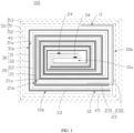
FIG. 1 is a first schematic structural top view of a battery cell according to an embodiment of this application. -
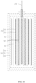
FIG. 2 is a first enlarged schematic diagram of a partial structure of a battery cell according to an embodiment of this application. -
FIG. 3 is a first schematic structural side view of a battery cell according to an embodiment of this application. -
FIG. 4 is a first schematic structural diagram of a positive electrode tab in a battery cell and a packaging bag being connected according to an embodiment of this application. -
FIG. 5 is a second schematic structural diagram of a positive electrode tab in a battery cell and a packaging bag being connected according to an embodiment of this application. -
FIG. 6 is a third schematic structural diagram of a positive electrode tab in a battery cell and a packaging bag being connected according to an embodiment of this application. -
FIG. 7 is a fourth schematic structural diagram of a positive electrode tab in a battery cell and a packaging bag being connected according to an embodiment of this application. -
FIG. 8 is a second schematic structural top view of a battery cell according to an embodiment of this application. -
FIG. 9 is a second enlarged schematic diagram of a partial structure of a battery cell according to an embodiment of this application. -
FIG. 10 is a second schematic structural side view of a battery cell according to an embodiment of this application. -
FIG. 11 is a third schematic structural top view of a battery cell according to an embodiment of this application. -
FIG. 12 is a third enlarged schematic diagram of a partial structure of a battery cell according to an embodiment of this application. -
FIG. 13 is a third schematic structural side view of a battery cell according to an embodiment of this application. - Reference signs of main components:
Battery cell 100 Electrode assembly 10 Winding center 10a Outermost electrode plate 10b First main plane 11 Second main plane 12 Positive electrode plate 20 Positive electrode current collector 21 First surface 21a Second surface 21b Positive electrode active material layer 22 First terminating end 23 First segment 231 Second segment 232 Positive electrode tab 24 Negative electrode plate 30 Negative electrode current collector 31 Third surface 31a Fourth surface 31b Negative electrode active material layer 32 Second terminating end 33 Negative electrode tab 34 First separator 40 Second separator 45 Packaging bag 50 Sealing portion 50a Metal layer 51 Fusion layer 52 Protective layer 53 Through hole 54 Depression 55 Conductive member 60 Sleeve groove 61 Tab adhesive layer 70, 70a, 70b, 70c Melting portion 71 Conductive portion 72 - The following describes the technical solutions in the embodiments of this application with reference to the accompanying drawings in the embodiments of this application. Apparently, the described embodiments are only some rather than all of the embodiments of this application.
- It should be noted that, when one component is deemed as being "connected to" another component, it can be directly connected to the another component, or there can be a component in between. When one component is deemed as being "disposed on" another component, it can be directly disposed on the another component, or there can be a component in between. The terms "top", "bottom", "upper", "lower", "left", "right", "front", "rear", and other similar expressions as used herein are for illustration only.
- Unless otherwise defined, all technical and scientific terms used herein shall have the same meanings as commonly understood by those skilled in the art to which this application pertains. The terms used herein in the specification of this application are for description of specific embodiments only without any intention to limit this application.
- An embodiment of this application provides a battery cell, including an electrode assembly and a packaging bag accommodating the electrode assembly. The electrode assembly includes a positive electrode plate, a first separator, and a negative electrode plate, the positive electrode plate, the first separator, and the negative electrode plate being wound. The positive electrode plate includes a positive electrode current collector and a positive electrode active material layer applied to the positive electrode current collector. The negative electrode plate includes a negative electrode current collector and a negative electrode active material layer applied to the negative electrode current collector. A winding center of the electrode assembly points a direction outside the electrode assembly, an electrode plate with a periphery not covered by the positive electrode plate or the negative electrode plate is defined as an outermost electrode plate of the electrode assembly, and the outermost electrode plate includes a positive electrode plate and a negative electrode plate.
- An embodiment of this application provides a battery, including a housing, where the battery further includes any one of the foregoing battery cells, and the battery cell is disposed in the housing.
- Another embodiment of this application provides an electric device, including the foregoing battery.
- In the battery cell, the battery, and the electric device provided in some embodiments of this application, when the battery cell is prone to abuse of a mechanical external force such as needle puncture, a short circuit preferentially occurs to the positive electrode plate and the negative electrode plate in the outermost electrode plate. For example, a short circuit occurs to the positive electrode plate or the negative electrode plate in the outermost electrode plate and to the metal layer in the packaging bag, and the short-circuit position is in the outermost electrode plate of the battery cell rather than in the battery cell. This facilitates heat dissipation and avoids combustion or explosion of the battery cell, thus improving the safety of the battery cell. As compared with a protection structure of a double-layer bare foil region provided at the outermost circle in the prior art, the present invention reduces the use of a layer of bare foil region while improving the safety of the battery cell, thus increasing the energy density of the battery cell.
- The following describes in detail some embodiments with reference to the accompanying drawings. In absence of conflicts, the following embodiments and features in the embodiments may be combined.
- Referring to
FIGs. 1 ,2 , and3 , abattery cell 100 in this embodiment includes an electrode assembly 10 and apackaging bag 50 accommodating the electrode assembly 10. The electrode assembly 10 includes apositive electrode plate 20 and anegative electrode plate 30 that are wound as well as afirst separator 40 disposed between thepositive electrode plate 20 and thenegative electrode plate 30. Thepositive electrode plate 20 includes a positive electrodecurrent collector 21 and a positive electrodeactive material layer 22 applied to the positive electrodecurrent collector 21. Thenegative electrode plate 30 includes a negative electrodecurrent collector 31 and a negative electrodeactive material layer 32 applied to the negative electrodecurrent collector 31. - The positive electrode
current collector 21 includes afirst surface 21a and asecond surface 21b opposite each other in a thickness direction of the positive electrodecurrent collector 21, where thefirst surface 21a and/or thesecond surface 21b is coated with the positive electrodeactive material layer 22. Thefirst surface 21a faces a windingcenter 10a, and thesecond surface 21b is back away from the windingcenter 10a. Thefirst surface 21a is defined as the inner side of the positive electrodecurrent collector 21, and thesecond surface 21b is defined as the outer side of the positive electrodecurrent collector 21. The negative electrodecurrent collector 31 includes athird surface 31a and afourth surface 31b opposite each other in a thickness direction of the negative electrodecurrent collector 31, where thethird surface 31a and/or thefourth surface 31b is coated with the negative electrodeactive material layer 32. Thethird surface 31a faces the windingcenter 10a, and thefourth surface 31b is back away from the windingcenter 10a. Thethird surface 31a is defined as the inner side of the negative electrodecurrent collector 31, and thefourth surface 31b is defined as the outer side of the negative electrodecurrent collector 31. - Referring to
FIG. 1 , a windingcenter 10a of the electrode assembly 10 points a direction outside the electrode assembly 10, an electrode plate with a periphery not covered by thepositive electrode plate 20 or thenegative electrode plate 30 is defined as anoutermost electrode plate 10b of the electrode assembly 10, and theoutermost electrode plate 10b includes apositive electrode plate 20 and anegative electrode plate 30. When thebattery cell 100 is prone to abuse of a mechanical external force such as needle puncture, a short circuit preferentially occurs to thepositive electrode plate 20 and thenegative electrode plate 30 in theoutermost electrode plate 10b. For example, a short circuit occurs to thepositive electrode plate 20 or thenegative electrode plate 30 in theoutermost electrode plate 10b and an electrode plate at the inner circle of theoutermost electrode plate 10b, or a short circuit occurs to thepositive electrode plate 20 or thenegative electrode plate 30 in theoutermost electrode plate 10b and the metal layer in thepackaging bag 50. In addition, the short-circuit position is in theoutermost electrode plate 10b of thebattery cell 100 rather than in thebattery cell 100, which facilitates heat dissipation and avoids combustion or explosion of thebattery cell 100, thus improving the safety of thebattery cell 100. - As compared with a protection structure of a double-layer bare foil region provided at the outermost circle in the prior art, a short circuit preferentially occurs to the
positive electrode plate 20 and thenegative electrode plate 30 that are included in theoutermost electrode plate 10b, which reduces the use of a layer of bare foil region while improving the safety of thebattery cell 100, thus increasing the energy density of thebattery cell 100. - Referring to
FIG. 1 , in some embodiments, in a thickness direction of the electrode assembly 10, the electrode assembly 10 includes a firstmain plane 11 and a secondmain plane 12 disposed opposite each other. The outermostpositive electrode plate 20 includes a first terminatingend 23, the first terminatingend 23 being disposed on the firstmain plane 11. The outermostnegative electrode plate 30 includes a second terminatingend 33, the second terminatingend 33 being disposed on the secondmain plane 12. - The first terminating
end 23 terminates on the firstmain plane 11 and the second terminatingend 33 terminates on the secondmain plane 12, allowing the first terminatingend 23 and the second terminatingend 33 to terminate on different side surfaces of thebattery cell 100. When the firstmain plane 11 and/or the secondmain plane 12 is prone to abuse of a mechanical external force such as needle puncture, a short circuit preferentially occurs to the corresponding first terminatingend 23 and/or the second terminatingend 33, so as to improve the safety of the firstmain plane 11 and the secondmain plane 12 of thebattery cell 100. In some embodiments, the first terminatingend 23 includes afirst segment 231 and asecond segment 232. In a winding direction of the first terminatingend 23, thesecond segment 232 is disposed at an outer end of thefirst segment 231. Thefirst segment 231 is disposed on the secondmain plane 12, and thesecond segment 232 is wound to the firstmain plane 11 after bypassing a corner of thebattery cell 100. The inner side of the positive electrodecurrent collector 21 corresponding to thefirst segment 231 is coated with the positive electrodeactive material layer 22, such that thefirst segment 231 and thenegative electrode plate 30 surrounded by it have capacity performance, thus increasing the energy density of thebattery cell 100. - A positive electrode
current collector 21 corresponding to thesecond segment 232 is uncoated with the positive electrodeactive material layer 22. Compared with the short circuit occurring between thepositive electrode plate 20 and thenegative electrode plate 30, the short circuit occurring to the positive electrodecurrent collector 21 and/or the negative electrodecurrent collector 31 is relatively safe. Therefore, the positive electrodecurrent collector 21 corresponding to thesecond segment 232 is uncoated with the positive electrodeactive material layer 22, such that the short circuit occurs to the positive electrodecurrent collector 21 when thebattery cell 100 is prone to abuse of a mechanical external force such as needle puncture. For example, a short circuit occurs to thesecond segment 232 and an electrode plate at the inner circle of theoutermost electrode plate 10b, or a short circuit occurs to thesecond segment 232 and the metal layer in thepackaging bag 50. In addition, the short-circuit position is in theoutermost electrode plate 10b of thebattery cell 100 rather than in thebattery cell 100, which facilitates heat dissipation and avoids combustion or explosion of thebattery cell 100, thus improving the safety of thebattery cell 100. - Referring to
FIGs. 1 and2 , in some embodiments, both sides of the positive electrodecurrent collector 21 corresponding to thefirst segment 231 are coated with the positive electrodeactive material layer 22. A positive electrodecurrent collector 21 corresponding to thesecond segment 232 is uncoated with the positive electrodeactive material layer 22. - In some embodiments, only the inner side of the positive electrode
current collector 21 corresponding to thefirst segment 231 is coated with the positive electrode active material layer 22 (referring toFIG. 7 ), and both sides of the positive electrodecurrent collector 21 connected to an inner end (that is, an end of thefirst segment 231 away from the second segment 232) of thefirst segment 231 are coated with the positive electrodeactive material layer 22. A positive electrodecurrent collector 21 corresponding to thesecond segment 232 is uncoated with the positive electrodeactive material layer 22. - In some embodiments, the positive electrode
current collector 21 corresponding to thefirst segment 231 transits from a current collector with both sides coated with the positive electrodeactive material layer 22 to a current collector with only the inner side coated with the positive electrode active material layer 22 (referring toFIG. 10 ), and the positive electrodecurrent collector 21 with the inner side coated with the positive electrodeactive material layer 22 surrounds at least half circle of thebattery cell 100. A positive electrodecurrent collector 21 corresponding to thesecond segment 232 is uncoated with the positive electrodeactive material layer 22. - In some embodiments, an occupation area proportion of the
second segment 232 on the firstmain plane 11 is greater than 0% and small than or equal to 100%. In some specific embodiments, the area proportion of thesecond segment 232 occupying the firstmain plane 11 is one of 10%, 20%, 30%, 40%, 50%, 60%, 70%, 80%, 90%, or the like. - Still referring to
FIG. 1 , the outer side of the negative electrodecurrent collector 31 corresponding to the second terminatingend 33 is uncoated with the negative electrodeactive material layer 32, allowing the short circuit to occur to the negative electrodecurrent collector 31 at the outer circle of thesecond segment 232 when thebattery cell 100 is prone to the abuse of a mechanical external force such as needle puncture, thus improving the safety of thebattery cell 100. In addition, the negative electrodecurrent collector 31 corresponding to thenegative electrode plate 30 surrounded by thesecond segment 232 bypassing the corner of thebattery cell 100 allows for one more opportunity of a safe short circuit between the positive electrodecurrent collector 21 and the negative electrodecurrent collector 31 at the corner of thebattery cell 100, thus improving the safety of thebattery cell 100. - It can be understood that the positive electrode
current collector 21, in thepositive electrode plate 20, with the outer side coated with the positive electrodeactive material layer 22 is surrounded outwards by thenegative electrode plate 30, and the inner side of the negative electrodecurrent collector 31 corresponding to thenegative electrode plate 30 is coated with the negative electrodeactive material layer 32, allowing for the positive electrodecurrent collector 21 coated with the positive electrodeactive material layer 22 and thenegative electrode plate 30 surrounding it to have capacity performance, thus increasing the energy density of thebattery cell 100. - Referring to
FIGs. 1 and2 , in some embodiments, only the inner side of the negative electrodecurrent collector 31 corresponding to the second terminatingend 33 is coated with the negative electrodeactive material layer 32, and the negative electrodecurrent collector 31 surrounds at least one cycle of the positive electrodecurrent collector 21, corresponding to the first terminatingend 23, with both sides coated with the positive electrodeactive material layer 22. Both sides of the negative electrodecurrent collector 31 connected to an inner end of the second terminatingend 33 are coated with the negative electrodeactive material layer 32. - In some embodiments, neither side of the negative electrode
current collector 31 corresponding to the second terminatingend 33 is coated with the negative electrodeactive material layer 32, and the negative electrodecurrent collector 31 surrounds at least one cycle of the positive electrodecurrent collector 21, corresponding to the first terminatingend 23, with one side coated with the positive electrode active material layer 22 (referring toFIG. 7 ). Both sides of the negative electrodecurrent collector 31 connected to an inner end of the second terminatingend 33 are coated with the negative electrodeactive material layer 32. - In some embodiments, the negative electrode
current collector 31 corresponding to the second terminatingend 33 transits from a current collector with the inner side coated with the negative electrodeactive material layer 32 to a current collector with neither side coated with the negative electrodeactive material layer 32, and the negative electrodecurrent collector 31 with neither side coated with the negative electrodeactive material layer 32 surrounds at least half circle of the positive electrodecurrent collector 21, corresponding to the first terminatingend 23, with one side coated with the positive electrode active material layer 22 (referring toFIG. 10 ). Both sides of the negative electrodecurrent collector 31 connected to an inner end of the second terminatingend 33 are coated with the negative electrodeactive material layer 32. - Referring to
FIGs. 1 and2 , in some embodiments, thebattery cell 100 further includes asecond separator 45. Thesecond separator 45 covers an end portion of the second terminatingend 33 and is configured to improve the safety of the end portion of the second terminatingend 33. The end portion of the second terminatingend 33 is a portion where a cut surface of the outermostnegative electrode plate 30 is located. In some specific embodiments, thesecond separator 45 covers both the end portion of the second terminatingend 33 and an end portion of thefirst segment 231 on the secondmain plane 12. - Referring to
FIG. 3 , thebattery cell 100 further includes apositive electrode tab 24 disposed on thepositive electrode plate 20 and anegative electrode tab 34 disposed on thenegative electrode plate 30. Thepackaging bag 50 includes afusion layer 52, ametal layer 51, and aprotective layer 53 stacked sequentially. Thefusion layer 52 is disposed on an inner side surface of themetal layer 51 and configured to be melted by heat to seal thepackaging bag 50. Theprotective layer 53 is disposed on an outer side surface of themetal layer 51 and configured to enhance the structural strength of thepackaging bag 50, avoiding the damage to the electrode assembly 10 due to breakage of thepackaging bag 50. - The
packaging bag 50 is provided with a sealingportion 50a, and thepositive electrode tab 24 is electrically connected to themetal layer 51 and extends from the sealingportion 50a, so as to improve the sealing performance of thepackaging bag 50. Specifically, the sealingportion 50a is formed through extension of thefusion layer 52, themetal layer 51, and theprotective layer 53 along the extension direction of the tab. - The
positive electrode tab 24 being electrically connected to themetal layer 51 allows the short circuit to occur preferentially to themetal layer 51 in thepackaging bag 50 and the positive electrodecurrent collector 21 when thebattery cell 100 is prone to abuse of a mechanical external force such as needle puncture. In addition, the short-circuit position is in thepackaging bag 50 at the outermost side of thebattery cell 100 rather than in thebattery cell 100. This facilitates heat dissipation and avoids combustion or explosion of thebattery cell 100, thus improving the safety of thebattery cell 100. - In some embodiments, the
packaging bag 50 further includes a bonding layer, where the bonding layer is disposed between thefusion layer 52 and themetal layer 51 and between themetal layer 51 and theprotective layer 53 and configured to improve the stability of connection between thefusion layer 52, themetal layer 51, and theprotective layer 53, improving the structural strength of thepackaging bag 50. - In some embodiments, the
metal layer 51 is made of aluminum or stainless steel, thefusion layer 52 is made of polyethylene plastic, and theprotective layer 53 is made of nylon or polyester resin. - Referring to
FIG. 4 , thefusion layer 52 in the sealingportion 50a is provided with a throughhole 54, and thepositive electrode tab 24 is electrically connected to themetal layer 51 via the throughhole 54. In addition, thebattery cell 100 further includes a tab adhesive layer 70 for thepositive electrode tab 24 to penetrate through, and the tab adhesive layer 70 is partially disposed in the sealingportion 50a and configured to further improve the sealing performance of thepackaging bag 50. - In different embodiments, the tab adhesive layer 70 is of a different structure. To distinguish different tab adhesive layers 70 in different embodiments, the tab adhesive layers 70 in different embodiments are respectively defined as a tab
adhesive layer 70a, a tabadhesive layer 70b, and a tabadhesive layer 70c. - Still referring to
FIG. 4 , in some embodiments, the tabadhesive layer 70a covers a portion of thepositive electrode tab 24 in the sealingportion 50a. The tabadhesive layer 70a is provided with amelting portion 71 corresponding to the throughhole 54, the meltingportion 71 is configured to melt synchronously with thefusion layer 52, so as to expose thepositive electrode tab 24 in themelting portion 71, and thepositive electrode tab 24 runs through the throughhole 54 to be electrically connected to themetal layer 51. - In the foregoing
battery cell 100, as the tabadhesive layer 70a is melted and combined with thefusion layer 52 and themelting portion 71 is disposed on the tabadhesive layer 70a, allowing the meltingportion 71 to melt synchronously with thefusion layer 52, thus improving the sealing performance of thebattery cell 100. The exposedpositive electrode tab 24 being electrically connected to themetal layer 51 via the throughhole 54 allows the short circuit to preferentially occur to themetal layer 51 and the positive electrodecurrent collector 21 when thebattery cell 100 is prone to abuse of a mechanical external force such as needle puncture, thus improving the safety of thebattery cell 100. - Referring to
FIG. 5 , in some embodiments, the tabadhesive layer 70b covers a portion of thepositive electrode tab 24 in the sealingportion 50a. The tabadhesive layer 70b is provided with aconductive portion 72 corresponding to the throughhole 54, theconductive portion 72 runs through the throughhole 54 and abuts against themetal layer 51, and thepositive electrode tab 24 is electrically connected to themetal layer 51 via theconductive portion 72. - In the foregoing
battery cell 100, the tabadhesive layer 70b being melted and combined with thefusion layer 52 improves the sealing performance of thebattery cell 100. As theconductive portion 72 is disposed on the tabadhesive layer 70b, and theconductive portion 72 runs through the throughhole 54 and abuts against themetal layer 51, thepositive electrode tab 24 is electrically connected to themetal layer 51, allowing the short circuit to preferentially occur to themetal layer 51 and the positive electrodecurrent collector 21 when thebattery cell 100 is prone to abuse of a mechanical external force such as needle puncture, thus improving the safety of thebattery cell 100. - Referring to
FIG. 6 , in some embodiments, the tabadhesive layer 70c covers a portion of thepositive electrode tab 24 in the sealingportion 50a. The tabadhesive layer 70c is a conductive adhesive layer, and a portion of the tabadhesive layer 70c corresponding to the throughhole 54 runs through the throughhole 54 and abuts against themetal layer 51 so as to be electrically connected to themetal layer 51. - In the foregoing
battery cell 100, the tabadhesive layer 70c being melted and combined with thefusion layer 52 improves the sealing performance of thebattery cell 100. As the portion of the tabadhesive layer 70c corresponding to the throughhole 54 runs through the throughhole 54 and abuts against themetal layer 51, the tabadhesive layer 70c made of a conductive adhesive enables thepositive electrode tab 24 to be electrically connected to themetal layer 51. This allows the short circuit to preferentially occur to themetal layer 51 and the positive electrodecurrent collector 21 when thebattery cell 100 is prone to abuse of a mechanical external force such as needle puncture, thus improving the safety of thebattery cell 100. - Referring to
FIG. 7 , in some embodiments, thebattery cell 100 further includes aconductive member 60. Theprotective layer 53 is provided with adepression 55 exposing themetal layer 51. A first end of theconductive member 60 is electrically connected to themetal layer 51 at thedepression 55, and a second end of theconductive member 60 is electrically connected to thepositive electrode tab 24 outside thepackaging bag 50. - In some specific embodiments, a
sleeve groove 61 is provided on a side of theconductive member 60 facing the sealingportion 50a, and theconductive member 60 sleeves an end portion of the sealingportion 50a via thesleeve groove 61. The central position of the conductive member 60 (that is, the second end of the conductive member 60) is for thepositive electrode tab 24 to pass through, thus allowing theconductive member 60 to be electrically connected to thepositive electrode tab 24. A circumferential side of the conductive member 60 (that is, the first end of the conductive member 60) penetrates through thedepression 55 to abut against themetal layer 51 in the sealingportion 50a, thus allowing theconductive member 60 to be electrically connected to themetal layer 51. - In the foregoing
battery cell 100, theconductive member 60 sleeves the end portion of the sealingportion 50a via thesleeve groove 61, thus improving the air tightness of thebattery cell 100. As theconductive member 60 is electrically connected to both thepositive electrode tab 24 and themetal layer 51, thepositive electrode tab 24 is electrically connected to themetal layer 51, allowing the short circuit to preferentially occur to themetal layer 51 and the positive electrodecurrent collector 21 when thebattery cell 100 is prone to abuse of a mechanical external force such as needle puncture, thus improving the safety of thebattery cell 100. - An embodiment of this application provides a battery (not shown), including a housing (not shown) and a
battery cell 100 disposed in the housing, and thebattery cell 100 may be any one of the battery cells in the foregoing embodiments. - In some embodiments, the battery further includes a circuit protection board (not shown). The circuit protection board is configured to monitor voltage, current, insulation status, state of charge, and the like of the
battery cell 100 to provide safe management during charging and discharging of the battery, alarm and emergency protection for possible faults, and safety and optimization control for operation of the battery. - An embodiment of this application provides an electric device (not shown), including the battery according to any one of the foregoing embodiments.
- The present invention is described below in detail using specific embodiments:
- Referring to
FIGs. 1 ,2 , and3 , a first terminatingend 23 in this embodiment terminates on the firstmain plane 11 and a second terminatingend 33 terminates on the secondmain plane 12. Both sides of a positive electrodecurrent collector 21 corresponding to thefirst segment 231 are coated with the positive electrodeactive material layer 22. A positive electrodecurrent collector 21 corresponding to thesecond segment 232 is uncoated with the positive electrodeactive material layer 22. An occupation area proportion of thesecond segment 232 on the firstmain plane 11 is greater than 0% and small than or equal to 100%. Only the inner side of the negative electrodecurrent collector 31 corresponding to the second terminatingend 33 is coated with the negative electrodeactive material layer 32, and the negative electrodecurrent collector 31 surrounds at least one cycle of the positive electrodecurrent collector 21, corresponding to the first terminatingend 23, with both sides coated with the positive electrodeactive material layer 22. Both sides of the negative electrodecurrent collector 31 connected to an inner end of the second terminatingend 33 are coated with the negative electrodeactive material layer 32. Thesecond separator 45 covers an end portion of the second terminatingend 33. - Referring to
FIGs. 8 ,9 , and10 , a first terminatingend 23 in this embodiment terminates on the firstmain plane 11 and a second terminatingend 33 terminates on the secondmain plane 12. Only the inner side of the positive electrodecurrent collector 21 corresponding to thefirst segment 231 is coated with the positive electrodeactive material layer 22, and both sides of the positive electrodecurrent collector 21 connected to an inner end of thefirst segment 231 are coated with the positive electrodeactive material layer 22. A positive electrodecurrent collector 21 corresponding to thesecond segment 232 is uncoated with the positive electrodeactive material layer 22. An occupation area proportion of thesecond segment 232 on the firstmain plane 11 is greater than 0% and small than or equal to 100%. Neither side of the negative electrodecurrent collector 31 corresponding to the second terminatingend 33 is coated with the negative electrodeactive material layer 32, and the negative electrodecurrent collector 31 surrounds at least one cycle of the positive electrodecurrent collector 21, corresponding to the first terminatingend 23, with one side coated with the positive electrodeactive material layer 22. Both sides of the negative electrodecurrent collector 31 connected to an inner end of the second terminatingend 33 are coated with the negative electrodeactive material layer 32. Thesecond separator 45 covers an end portion of the second terminatingend 33. - Referring to
FIGs. 11 ,12 , and13 , a first terminatingend 23 in this embodiment terminates on the firstmain plane 11 and a second terminatingend 33 terminates on the secondmain plane 12. The positive electrodecurrent collector 21 corresponding to thefirst segment 231 transits from a current collector with both sides coated with the positive electrodeactive material layer 22 to a current collector with only the inner side coated with the positive electrode active material layer 22 (referring toFIG. 7 ), and the positive electrodecurrent collector 21 with the inner side coated with the positive electrodeactive material layer 22 surrounds at least half circle of thebattery cell 100. A positive electrodecurrent collector 21 corresponding to thesecond segment 232 is uncoated with the positive electrodeactive material layer 22. An occupation area proportion of thesecond segment 232 on the firstmain plane 11 is greater than 0% and small than or equal to 100%. The negative electrodecurrent collector 31 corresponding to the second terminatingend 33 transits from a current collector with the inner side coated with the negative electrodeactive material layer 32 to a current collector with neither side coated with the negative electrodeactive material layer 32, and the negative electrodecurrent collector 31 with neither side coated with the negative electrodeactive material layer 32 surrounds at least half circle of the positive electrodecurrent collector 21, corresponding to the first terminatingend 23, with one side coated with the positive electrodeactive material layer 22. Both sides of the negative electrodecurrent collector 31 connected to an inner end of the second terminatingend 33 are coated with the negative electrodeactive material layer 32. Thesecond separator 45 covers an end portion of the second terminatingend 33. - In addition, those of ordinary skill in the art should be aware of that the foregoing embodiments are only intended to describe this application, but not to limit this application. Appropriate modifications and variations made to the foregoing embodiments without departing from the essential spirit and scope of this application all fall within the scope of this application.
Claims (13)
- A battery cell, comprising an electrode assembly and a packaging bag accommodating the electrode assembly, wherein the electrode assembly comprises a positive electrode plate, a first separator, and a negative electrode plate wound together, wherein the positive electrode plate comprises a positive electrode current collector and a positive electrode active material layer applied to the positive electrode current collector, the negative electrode plate comprises a negative electrode current collector and a negative electrode active material layer applied to the negative electrode current collector, a winding center of the electrode assembly points a direction outside the electrode assembly, an electrode plate with a periphery not covered by the positive electrode plate or the negative electrode plate is defined as an outermost electrode plate of the electrode assembly, and the outermost electrode plate comprises a positive electrode plate and a negative electrode plate.
- The battery cell according to claim 1, wherein in a thickness direction of the electrode assembly, the electrode assembly comprises a first main plane and a second main plane disposed opposite each other, the outermost positive electrode plate comprises a first terminating end, the first terminating end is disposed on the first main plane, the outermost negative electrode plate comprises a second terminating end, and the second terminating end is disposed on the second main plane.
- The battery cell according to claim 2, wherein the first terminating end comprises a first segment and a second segment, and in a winding direction of the first terminating end, the second segment is disposed at an outer end of the first segment; and
the first segment is disposed on the second main plane, the second segment is wound to the first main plane after bypassing a corner of the battery cell, an inner side of a positive electrode current collector corresponding to the first segment is coated with the positive electrode active material layer, and a positive electrode current collector corresponding to the second segment is uncoated with the positive electrode active material layer. - The battery cell according to claim 2, wherein an outer side of a negative electrode current collector corresponding to the second terminating end is uncoated with the negative electrode active material layer.
- The battery cell according to claim 2, wherein the battery cell further comprises a second separator, and the second separator covers an end portion of the second terminating end.
- The battery cell according to claim 1, wherein the battery cell further comprises a positive electrode tab disposed on the positive electrode plate;the packaging bag comprises a fusion layer, a metal layer, and a protective layer stacked sequentially, wherein the fusion layer is disposed on an inner side surface of the metal layer and configured to be melted by heat to seal the packaging bag, and the protective layer is disposed on an outer side surface of the metal layer; andthe packaging bag is provided with a sealing portion, and the positive electrode tab is electrically connected to the metal layer and extends from the sealing portion.
- The battery cell according to claim 6, wherein the fusion layer in the sealing portion is provided with a through hole, and the positive electrode tab is electrically connected to the metal layer via the through hole; and
the battery cell further comprises a tab adhesive layer for the positive electrode tab to penetrate through, and the tab adhesive layer is partially disposed in the sealing portion. - The battery cell according to claim 7, wherein the tab adhesive layer is provided with a melting portion corresponding to the through hole, the melting portion is configured to melt synchronously with the fusion layer, so as to expose the positive electrode tab in the melting portion, and the positive electrode tab runs through the through hole to be electrically connected to the metal layer.
- The battery cell according to claim 7, wherein the tab adhesive layer is provided with a conductive portion corresponding to the through hole, and the conductive portion runs through the through hole and abuts against the metal layer to be electrically connected to the metal layer.
- The battery cell according to claim 7, wherein the tab adhesive layer is a conductive adhesive layer, and a portion of the tab adhesive layer corresponding to the through hole runs through the through hole and abuts against the metal layer to be electrically connected to the metal layer.
- The battery cell according to claim 6, wherein the battery cell further comprises a conductive member, the protective layer is provided with a depression exposing the metal layer, an end of the conductive member is electrically connected to the metal layer at the depression, and a second end of the conductive member is electrically connected to the positive electrode tab outside the packaging bag.
- A battery, comprising a housing, wherein the battery further comprises the battery cell according to any one of claims 1 to 11, and the battery cell is disposed in the housing.
- An electric device, comprising the battery according to claim 12.
Applications Claiming Priority (1)
| Application Number | Priority Date | Filing Date | Title |
|---|---|---|---|
| PCT/CN2021/118150 WO2023039706A1 (en) | 2021-09-14 | 2021-09-14 | Battery cell, battery and electrical device |
Publications (2)
| Publication Number | Publication Date |
|---|---|
| EP4394994A1 true EP4394994A1 (en) | 2024-07-03 |
| EP4394994A4 EP4394994A4 (en) | 2025-06-11 |
Family
ID=82236440
Family Applications (1)
| Application Number | Title | Priority Date | Filing Date |
|---|---|---|---|
| EP21957000.9A Pending EP4394994A4 (en) | 2021-09-14 | 2021-09-14 | Battery cell, battery and electrical device |
Country Status (4)
| Country | Link |
|---|---|
| US (1) | US20240222686A1 (en) |
| EP (1) | EP4394994A4 (en) |
| CN (1) | CN114730943B (en) |
| WO (1) | WO2023039706A1 (en) |
Families Citing this family (2)
| Publication number | Priority date | Publication date | Assignee | Title |
|---|---|---|---|---|
| CN115275460B (en) * | 2022-08-30 | 2024-08-20 | 宁德新能源科技有限公司 | Cells, Batteries and Electrical Equipment |
| CN116565340B (en) * | 2023-07-10 | 2024-03-12 | 宁德新能源科技有限公司 | Batteries and electrical equipment |
Family Cites Families (15)
| Publication number | Priority date | Publication date | Assignee | Title |
|---|---|---|---|---|
| CN201289883Y (en) * | 2008-08-01 | 2009-08-12 | 上海比亚迪有限公司 | Electric core of coiling type lithium battery and coiling type lithium battery |
| KR20130051890A (en) * | 2011-11-10 | 2013-05-21 | 주식회사 엘지화학 | Battery cell of novel structure |
| CN102694202B (en) * | 2012-06-29 | 2014-07-30 | 广东凯德能源科技有限公司 | Button type lithium ion battery |
| CN203589158U (en) * | 2013-11-29 | 2014-05-07 | 徐敖奎 | High-voltage lithium ion battery |
| CN107546421B (en) * | 2016-06-28 | 2024-04-05 | 宁德新能源科技有限公司 | Winding type battery cell |
| CN206040883U (en) * | 2016-09-22 | 2017-03-22 | 宁德新能源科技有限公司 | Winding - type batteries |
| CN206451767U (en) * | 2016-12-27 | 2017-08-29 | 宁德新能源科技有限公司 | A kind of takeup type battery core |
| CN206401457U (en) * | 2016-12-27 | 2017-08-11 | 宁德新能源科技有限公司 | A kind of takeup type battery core |
| CN109980230A (en) * | 2017-12-28 | 2019-07-05 | 宁德新能源科技有限公司 | Takeup type battery core and electrochemical appliance |
| CN208189689U (en) * | 2018-02-09 | 2018-12-04 | 深圳市沃能新能源有限公司 | Anti-explosion battery |
| CN118099552A (en) * | 2018-03-06 | 2024-05-28 | 宁德新能源科技有限公司 | Wound battery cell |
| CN110808377B (en) * | 2018-08-06 | 2021-04-27 | 宁德新能源科技有限公司 | Cells, Batteries and Electronic Devices |
| KR102325036B1 (en) * | 2018-08-29 | 2021-11-11 | 주식회사 엘지에너지솔루션 | The Pouch Type Secondary Battery And The Pouch For The Secondary Battery |
| KR20200086932A (en) * | 2019-01-10 | 2020-07-20 | 주식회사 엘지화학 | Electrode assembly and methode for maenufacture the electrode assembly and secondary battery therewith the electrode assembly |
| CN112864498A (en) * | 2021-03-19 | 2021-05-28 | 惠州锂威新能源科技有限公司 | Multi-tab battery cell and preparation method thereof |
-
2021
- 2021-09-14 WO PCT/CN2021/118150 patent/WO2023039706A1/en not_active Ceased
- 2021-09-14 CN CN202180006011.9A patent/CN114730943B/en active Active
- 2021-09-14 EP EP21957000.9A patent/EP4394994A4/en active Pending
-
2024
- 2024-03-13 US US18/603,681 patent/US20240222686A1/en active Pending
Also Published As
| Publication number | Publication date |
|---|---|
| CN114730943A (en) | 2022-07-08 |
| CN114730943B (en) | 2024-08-16 |
| US20240222686A1 (en) | 2024-07-04 |
| WO2023039706A1 (en) | 2023-03-23 |
| EP4394994A4 (en) | 2025-06-11 |
Similar Documents
| Publication | Publication Date | Title |
|---|---|---|
| EP2136429B1 (en) | Electrode assembly and lithium secondary battery with same | |
| KR100449757B1 (en) | Battery unit and secondary battery applying the such | |
| KR100958649B1 (en) | Battery unit, a winding method thereof, and a lithium secondary battery manufactured using the same | |
| KR100496305B1 (en) | Pouched-type lithium secondary battery and the fabrication method thereof | |
| KR20040054128A (en) | Pouched-type lithium secondary battery | |
| US20240222686A1 (en) | Battery cell, battery, and electric device | |
| WO2011115464A2 (en) | Pouch type case and battery pack including same | |
| KR101734327B1 (en) | Pouch type secondary battery | |
| US20250201936A1 (en) | Electrode for secondary batteries | |
| KR20230109950A (en) | Secondary Battery | |
| KR20230108643A (en) | Pouch-type Battery Cell with improved safety and battery module comprising the same | |
| KR101146465B1 (en) | Pouch type secondary battery and the fabrication method thereof | |
| US20230299432A1 (en) | Electrode-Lead-Integrated Electrode Assembly and Method of Manufacturing the Same | |
| US12597629B2 (en) | Method of manufacturing secondary battery | |
| KR100551397B1 (en) | Pouch Type Lithium Secondary Battery | |
| US20220006162A1 (en) | Battery | |
| KR20220158378A (en) | Secondary battery | |
| KR20230067972A (en) | Secondary Battery | |
| KR20220033944A (en) | The Electrode Assembly And The Secondary Battery | |
| KR102956955B1 (en) | Battery cell including electrode tabs on which stress relief portions are formed | |
| KR102876010B1 (en) | Secondary battery | |
| US20250132423A1 (en) | Pouch-type battery cell and battery module including same | |
| US20260088306A1 (en) | Current collector and battery | |
| US20260128385A1 (en) | Wound electrode assembly | |
| KR102962577B1 (en) | Electrode assembly and secondary battery including the same |
Legal Events
| Date | Code | Title | Description |
|---|---|---|---|
| STAA | Information on the status of an ep patent application or granted ep patent |
Free format text: STATUS: THE INTERNATIONAL PUBLICATION HAS BEEN MADE |
|
| PUAI | Public reference made under article 153(3) epc to a published international application that has entered the european phase |
Free format text: ORIGINAL CODE: 0009012 |
|
| STAA | Information on the status of an ep patent application or granted ep patent |
Free format text: STATUS: REQUEST FOR EXAMINATION WAS MADE |
|
| 17P | Request for examination filed |
Effective date: 20240326 |
|
| AK | Designated contracting states |
Kind code of ref document: A1 Designated state(s): AL AT BE BG CH CY CZ DE DK EE ES FI FR GB GR HR HU IE IS IT LI LT LU LV MC MK MT NL NO PL PT RO RS SE SI SK SM TR |
|
| DAV | Request for validation of the european patent (deleted) | ||
| DAX | Request for extension of the european patent (deleted) | ||
| A4 | Supplementary search report drawn up and despatched |
Effective date: 20250514 |
|
| RIC1 | Information provided on ipc code assigned before grant |
Ipc: H01M 50/183 20210101ALI20250508BHEP Ipc: H01M 50/178 20210101ALI20250508BHEP Ipc: H01M 50/129 20210101ALI20250508BHEP Ipc: H01M 50/121 20210101ALI20250508BHEP Ipc: H01M 50/119 20210101ALI20250508BHEP Ipc: H01M 50/105 20210101ALI20250508BHEP Ipc: H01M 10/04 20060101ALI20250508BHEP Ipc: H01M 10/0587 20100101AFI20250508BHEP |