EP4394944A1 - Positive electrode active material, electrochemical device, and electronic device - Google Patents
Positive electrode active material, electrochemical device, and electronic device Download PDFInfo
- Publication number
- EP4394944A1 EP4394944A1 EP21967537.8A EP21967537A EP4394944A1 EP 4394944 A1 EP4394944 A1 EP 4394944A1 EP 21967537 A EP21967537 A EP 21967537A EP 4394944 A1 EP4394944 A1 EP 4394944A1
- Authority
- EP
- European Patent Office
- Prior art keywords
- active material
- positive active
- application
- core
- moles
- Prior art date
- Legal status (The legal status is an assumption and is not a legal conclusion. Google has not performed a legal analysis and makes no representation as to the accuracy of the status listed.)
- Pending
Links
- 239000007774 positive electrode material Substances 0.000 title claims abstract description 107
- 239000000463 material Substances 0.000 claims abstract description 132
- 239000011159 matrix material Substances 0.000 claims abstract description 69
- 239000002245 particle Substances 0.000 claims description 34
- 229910052751 metal Inorganic materials 0.000 claims description 22
- 229910052782 aluminium Inorganic materials 0.000 claims description 20
- 229910052748 manganese Inorganic materials 0.000 claims description 9
- 229910052719 titanium Inorganic materials 0.000 claims description 9
- 229910052726 zirconium Inorganic materials 0.000 claims description 9
- 229910052802 copper Inorganic materials 0.000 claims description 8
- 229910052721 tungsten Inorganic materials 0.000 claims description 7
- 229910052727 yttrium Inorganic materials 0.000 claims description 7
- 229910052684 Cerium Inorganic materials 0.000 claims description 6
- 229910052787 antimony Inorganic materials 0.000 claims description 6
- 229910052791 calcium Inorganic materials 0.000 claims description 6
- 229910052804 chromium Inorganic materials 0.000 claims description 6
- 229910052738 indium Inorganic materials 0.000 claims description 6
- 229910052742 iron Inorganic materials 0.000 claims description 6
- 229910052746 lanthanum Inorganic materials 0.000 claims description 6
- 229910052745 lead Inorganic materials 0.000 claims description 6
- 229910052749 magnesium Inorganic materials 0.000 claims description 6
- 229910052758 niobium Inorganic materials 0.000 claims description 6
- 229910052718 tin Inorganic materials 0.000 claims description 6
- 229910052720 vanadium Inorganic materials 0.000 claims description 6
- 229910052725 zinc Inorganic materials 0.000 claims description 6
- 238000012546 transfer Methods 0.000 abstract description 11
- 230000002829 reductive effect Effects 0.000 abstract description 2
- 239000011572 manganese Substances 0.000 description 76
- 239000010410 layer Substances 0.000 description 72
- HBBGRARXTFLTSG-UHFFFAOYSA-N Lithium ion Chemical compound [Li+] HBBGRARXTFLTSG-UHFFFAOYSA-N 0.000 description 37
- 229910001416 lithium ion Inorganic materials 0.000 description 37
- -1 polypropylene Polymers 0.000 description 37
- 239000010936 titanium Substances 0.000 description 29
- 238000005245 sintering Methods 0.000 description 28
- 229910012406 LiNi0.5 Inorganic materials 0.000 description 27
- GWEVSGVZZGPLCZ-UHFFFAOYSA-N Titan oxide Chemical compound O=[Ti]=O GWEVSGVZZGPLCZ-UHFFFAOYSA-N 0.000 description 19
- 239000011230 binding agent Substances 0.000 description 17
- 239000010408 film Substances 0.000 description 16
- PXHVJJICTQNCMI-UHFFFAOYSA-N nickel Substances [Ni] PXHVJJICTQNCMI-UHFFFAOYSA-N 0.000 description 16
- 239000011164 primary particle Substances 0.000 description 13
- 239000006258 conductive agent Substances 0.000 description 12
- 239000008151 electrolyte solution Substances 0.000 description 12
- 239000002243 precursor Substances 0.000 description 12
- OKTJSMMVPCPJKN-UHFFFAOYSA-N Carbon Chemical compound [C] OKTJSMMVPCPJKN-UHFFFAOYSA-N 0.000 description 10
- 239000004743 Polypropylene Substances 0.000 description 10
- 238000002156 mixing Methods 0.000 description 10
- 229920001155 polypropylene Polymers 0.000 description 10
- 229910032387 LiCoO2 Inorganic materials 0.000 description 9
- 239000004698 Polyethylene Substances 0.000 description 9
- 229910052744 lithium Inorganic materials 0.000 description 9
- 229920000573 polyethylene Polymers 0.000 description 9
- 238000012360 testing method Methods 0.000 description 9
- 238000007599 discharging Methods 0.000 description 8
- 229910052759 nickel Inorganic materials 0.000 description 8
- 229920000642 polymer Polymers 0.000 description 8
- 230000000052 comparative effect Effects 0.000 description 7
- 239000011888 foil Substances 0.000 description 7
- 238000012935 Averaging Methods 0.000 description 6
- RYGMFSIKBFXOCR-UHFFFAOYSA-N Copper Chemical compound [Cu] RYGMFSIKBFXOCR-UHFFFAOYSA-N 0.000 description 6
- MCMNRKCIXSYSNV-UHFFFAOYSA-N Zirconium dioxide Chemical compound O=[Zr]=O MCMNRKCIXSYSNV-UHFFFAOYSA-N 0.000 description 6
- XAGFODPZIPBFFR-UHFFFAOYSA-N aluminium Chemical compound [Al] XAGFODPZIPBFFR-UHFFFAOYSA-N 0.000 description 6
- QVGXLLKOCUKJST-UHFFFAOYSA-N atomic oxygen Chemical compound [O] QVGXLLKOCUKJST-UHFFFAOYSA-N 0.000 description 6
- 239000010949 copper Substances 0.000 description 6
- 239000013078 crystal Substances 0.000 description 6
- 230000001351 cycling effect Effects 0.000 description 6
- 230000014759 maintenance of location Effects 0.000 description 6
- 238000000034 method Methods 0.000 description 6
- 239000000203 mixture Substances 0.000 description 6
- 239000007773 negative electrode material Substances 0.000 description 6
- 239000001301 oxygen Substances 0.000 description 6
- 229910052760 oxygen Inorganic materials 0.000 description 6
- 239000002131 composite material Substances 0.000 description 5
- 150000002484 inorganic compounds Chemical class 0.000 description 5
- 229910010272 inorganic material Inorganic materials 0.000 description 5
- 229910003002 lithium salt Inorganic materials 0.000 description 5
- 159000000002 lithium salts Chemical class 0.000 description 5
- 239000011163 secondary particle Substances 0.000 description 5
- 239000000758 substrate Substances 0.000 description 5
- 229910001290 LiPF6 Inorganic materials 0.000 description 4
- 229920002125 Sokalan® Polymers 0.000 description 4
- 239000012298 atmosphere Substances 0.000 description 4
- 230000005540 biological transmission Effects 0.000 description 4
- 239000011575 calcium Substances 0.000 description 4
- 229910052799 carbon Inorganic materials 0.000 description 4
- 239000003575 carbonaceous material Substances 0.000 description 4
- 150000001875 compounds Chemical class 0.000 description 4
- 239000011889 copper foil Substances 0.000 description 4
- 238000001035 drying Methods 0.000 description 4
- XEEYBQQBJWHFJM-UHFFFAOYSA-N iron Substances [Fe] XEEYBQQBJWHFJM-UHFFFAOYSA-N 0.000 description 4
- 239000011777 magnesium Substances 0.000 description 4
- 239000004745 nonwoven fabric Substances 0.000 description 4
- 239000003960 organic solvent Substances 0.000 description 4
- 239000004584 polyacrylic acid Substances 0.000 description 4
- 238000002360 preparation method Methods 0.000 description 4
- 239000002002 slurry Substances 0.000 description 4
- 230000007704 transition Effects 0.000 description 4
- XLYOFNOQVPJJNP-UHFFFAOYSA-N water Chemical compound O XLYOFNOQVPJJNP-UHFFFAOYSA-N 0.000 description 4
- 239000011701 zinc Substances 0.000 description 4
- WEVYAHXRMPXWCK-UHFFFAOYSA-N Acetonitrile Chemical compound CC#N WEVYAHXRMPXWCK-UHFFFAOYSA-N 0.000 description 3
- OIFBSDVPJOWBCH-UHFFFAOYSA-N Diethyl carbonate Chemical compound CCOC(=O)OCC OIFBSDVPJOWBCH-UHFFFAOYSA-N 0.000 description 3
- XEKOWRVHYACXOJ-UHFFFAOYSA-N Ethyl acetate Chemical compound CCOC(C)=O XEKOWRVHYACXOJ-UHFFFAOYSA-N 0.000 description 3
- KMTRUDSVKNLOMY-UHFFFAOYSA-N Ethylene carbonate Chemical compound O=C1OCCO1 KMTRUDSVKNLOMY-UHFFFAOYSA-N 0.000 description 3
- 102000004310 Ion Channels Human genes 0.000 description 3
- WHXSMMKQMYFTQS-UHFFFAOYSA-N Lithium Chemical compound [Li] WHXSMMKQMYFTQS-UHFFFAOYSA-N 0.000 description 3
- ZMXDDKWLCZADIW-UHFFFAOYSA-N N,N-Dimethylformamide Chemical compound CN(C)C=O ZMXDDKWLCZADIW-UHFFFAOYSA-N 0.000 description 3
- SECXISVLQFMRJM-UHFFFAOYSA-N N-Methylpyrrolidone Chemical compound CN1CCCC1=O SECXISVLQFMRJM-UHFFFAOYSA-N 0.000 description 3
- 239000004952 Polyamide Substances 0.000 description 3
- VYPSYNLAJGMNEJ-UHFFFAOYSA-N Silicium dioxide Chemical compound O=[Si]=O VYPSYNLAJGMNEJ-UHFFFAOYSA-N 0.000 description 3
- HEMHJVSKTPXQMS-UHFFFAOYSA-M Sodium hydroxide Chemical compound [OH-].[Na+] HEMHJVSKTPXQMS-UHFFFAOYSA-M 0.000 description 3
- 229910021383 artificial graphite Inorganic materials 0.000 description 3
- 239000002134 carbon nanofiber Substances 0.000 description 3
- 239000002041 carbon nanotube Substances 0.000 description 3
- 239000008367 deionised water Substances 0.000 description 3
- 229910021641 deionized water Inorganic materials 0.000 description 3
- 239000003792 electrolyte Substances 0.000 description 3
- 230000006870 function Effects 0.000 description 3
- 239000002184 metal Substances 0.000 description 3
- 238000001000 micrograph Methods 0.000 description 3
- 229920000058 polyacrylate Polymers 0.000 description 3
- 229920002647 polyamide Polymers 0.000 description 3
- 229920000139 polyethylene terephthalate Polymers 0.000 description 3
- 239000005020 polyethylene terephthalate Substances 0.000 description 3
- 229920001721 polyimide Polymers 0.000 description 3
- 229920001343 polytetrafluoroethylene Polymers 0.000 description 3
- 239000004810 polytetrafluoroethylene Substances 0.000 description 3
- 229920002981 polyvinylidene fluoride Polymers 0.000 description 3
- 229920000036 polyvinylpyrrolidone Polymers 0.000 description 3
- 239000001267 polyvinylpyrrolidone Substances 0.000 description 3
- 235000013855 polyvinylpyrrolidone Nutrition 0.000 description 3
- RUOJZAUFBMNUDX-UHFFFAOYSA-N propylene carbonate Chemical compound CC1COC(=O)O1 RUOJZAUFBMNUDX-UHFFFAOYSA-N 0.000 description 3
- 238000007789 sealing Methods 0.000 description 3
- 238000007086 side reaction Methods 0.000 description 3
- 229910052814 silicon oxide Inorganic materials 0.000 description 3
- 239000000243 solution Substances 0.000 description 3
- 239000002904 solvent Substances 0.000 description 3
- 238000003756 stirring Methods 0.000 description 3
- 229920003048 styrene butadiene rubber Polymers 0.000 description 3
- 239000000126 substance Substances 0.000 description 3
- 239000002335 surface treatment layer Substances 0.000 description 3
- ZZXUZKXVROWEIF-UHFFFAOYSA-N 1,2-butylene carbonate Chemical compound CCC1COC(=O)O1 ZZXUZKXVROWEIF-UHFFFAOYSA-N 0.000 description 2
- YEJRWHAVMIAJKC-UHFFFAOYSA-N 4-Butyrolactone Chemical compound O=C1CCCO1 YEJRWHAVMIAJKC-UHFFFAOYSA-N 0.000 description 2
- BJWMSGRKJIOCNR-UHFFFAOYSA-N 4-ethenyl-1,3-dioxolan-2-one Chemical compound C=CC1COC(=O)O1 BJWMSGRKJIOCNR-UHFFFAOYSA-N 0.000 description 2
- SBLRHMKNNHXPHG-UHFFFAOYSA-N 4-fluoro-1,3-dioxolan-2-one Chemical compound FC1COC(=O)O1 SBLRHMKNNHXPHG-UHFFFAOYSA-N 0.000 description 2
- OZJPLYNZGCXSJM-UHFFFAOYSA-N 5-valerolactone Chemical compound O=C1CCCCO1 OZJPLYNZGCXSJM-UHFFFAOYSA-N 0.000 description 2
- 229920000049 Carbon (fiber) Polymers 0.000 description 2
- XTHFKEDIFFGKHM-UHFFFAOYSA-N Dimethoxyethane Chemical compound COCCOC XTHFKEDIFFGKHM-UHFFFAOYSA-N 0.000 description 2
- IAZDPXIOMUYVGZ-UHFFFAOYSA-N Dimethylsulphoxide Chemical compound CS(C)=O IAZDPXIOMUYVGZ-UHFFFAOYSA-N 0.000 description 2
- ZHNUHDYFZUAESO-UHFFFAOYSA-N Formamide Chemical compound NC=O ZHNUHDYFZUAESO-UHFFFAOYSA-N 0.000 description 2
- WMFOQBRAJBCJND-UHFFFAOYSA-M Lithium hydroxide Chemical compound [Li+].[OH-] WMFOQBRAJBCJND-UHFFFAOYSA-M 0.000 description 2
- WYURNTSHIVDZCO-UHFFFAOYSA-N Tetrahydrofuran Chemical compound C1CCOC1 WYURNTSHIVDZCO-UHFFFAOYSA-N 0.000 description 2
- XLOMVQKBTHCTTD-UHFFFAOYSA-N Zinc monoxide Chemical compound [Zn]=O XLOMVQKBTHCTTD-UHFFFAOYSA-N 0.000 description 2
- 239000006230 acetylene black Substances 0.000 description 2
- 239000012670 alkaline solution Substances 0.000 description 2
- PNEYBMLMFCGWSK-UHFFFAOYSA-N aluminium oxide Inorganic materials [O-2].[O-2].[O-2].[Al+3].[Al+3] PNEYBMLMFCGWSK-UHFFFAOYSA-N 0.000 description 2
- DIZPMCHEQGEION-UHFFFAOYSA-H aluminium sulfate (anhydrous) Chemical compound [Al+3].[Al+3].[O-]S([O-])(=O)=O.[O-]S([O-])(=O)=O.[O-]S([O-])(=O)=O DIZPMCHEQGEION-UHFFFAOYSA-H 0.000 description 2
- TZCXTZWJZNENPQ-UHFFFAOYSA-L barium sulfate Chemical compound [Ba+2].[O-]S([O-])(=O)=O TZCXTZWJZNENPQ-UHFFFAOYSA-L 0.000 description 2
- 238000003490 calendering Methods 0.000 description 2
- 239000003990 capacitor Substances 0.000 description 2
- 239000004917 carbon fiber Substances 0.000 description 2
- 229910021393 carbon nanotube Inorganic materials 0.000 description 2
- 239000001768 carboxy methyl cellulose Substances 0.000 description 2
- 238000006243 chemical reaction Methods 0.000 description 2
- 239000011248 coating agent Substances 0.000 description 2
- 238000000576 coating method Methods 0.000 description 2
- 229910000361 cobalt sulfate Inorganic materials 0.000 description 2
- 229940044175 cobalt sulfate Drugs 0.000 description 2
- KTVIXTQDYHMGHF-UHFFFAOYSA-L cobalt(2+) sulfate Chemical compound [Co+2].[O-]S([O-])(=O)=O KTVIXTQDYHMGHF-UHFFFAOYSA-L 0.000 description 2
- 229920001940 conductive polymer Polymers 0.000 description 2
- 229910052593 corundum Inorganic materials 0.000 description 2
- 238000005520 cutting process Methods 0.000 description 2
- VUPKGFBOKBGHFZ-UHFFFAOYSA-N dipropyl carbonate Chemical compound CCCOC(=O)OCCC VUPKGFBOKBGHFZ-UHFFFAOYSA-N 0.000 description 2
- 238000009826 distribution Methods 0.000 description 2
- 230000000694 effects Effects 0.000 description 2
- RTZKZFJDLAIYFH-UHFFFAOYSA-N ether Substances CCOCC RTZKZFJDLAIYFH-UHFFFAOYSA-N 0.000 description 2
- JBTWLSYIZRCDFO-UHFFFAOYSA-N ethyl methyl carbonate Chemical compound CCOC(=O)OC JBTWLSYIZRCDFO-UHFFFAOYSA-N 0.000 description 2
- FKRCODPIKNYEAC-UHFFFAOYSA-N ethyl propionate Chemical compound CCOC(=O)CC FKRCODPIKNYEAC-UHFFFAOYSA-N 0.000 description 2
- CJNBYAVZURUTKZ-UHFFFAOYSA-N hafnium(iv) oxide Chemical compound O=[Hf]=O CJNBYAVZURUTKZ-UHFFFAOYSA-N 0.000 description 2
- 229910021385 hard carbon Inorganic materials 0.000 description 2
- 239000010954 inorganic particle Substances 0.000 description 2
- 239000013067 intermediate product Substances 0.000 description 2
- 238000010884 ion-beam technique Methods 0.000 description 2
- 229940099596 manganese sulfate Drugs 0.000 description 2
- 239000011702 manganese sulphate Substances 0.000 description 2
- 235000007079 manganese sulphate Nutrition 0.000 description 2
- SQQMAOCOWKFBNP-UHFFFAOYSA-L manganese(II) sulfate Chemical compound [Mn+2].[O-]S([O-])(=O)=O SQQMAOCOWKFBNP-UHFFFAOYSA-L 0.000 description 2
- 238000010299 mechanically pulverizing process Methods 0.000 description 2
- 239000002931 mesocarbon microbead Substances 0.000 description 2
- 239000007769 metal material Substances 0.000 description 2
- VNWKTOKETHGBQD-UHFFFAOYSA-N methane Chemical compound C VNWKTOKETHGBQD-UHFFFAOYSA-N 0.000 description 2
- TZIHFWKZFHZASV-UHFFFAOYSA-N methyl formate Chemical compound COC=O TZIHFWKZFHZASV-UHFFFAOYSA-N 0.000 description 2
- KKQAVHGECIBFRQ-UHFFFAOYSA-N methyl propyl carbonate Chemical compound CCCOC(=O)OC KKQAVHGECIBFRQ-UHFFFAOYSA-N 0.000 description 2
- 229910021382 natural graphite Inorganic materials 0.000 description 2
- LGQLOGILCSXPEA-UHFFFAOYSA-L nickel sulfate Chemical compound [Ni+2].[O-]S([O-])(=O)=O LGQLOGILCSXPEA-UHFFFAOYSA-L 0.000 description 2
- 229940053662 nickel sulfate Drugs 0.000 description 2
- 229910000363 nickel(II) sulfate Inorganic materials 0.000 description 2
- 230000036961 partial effect Effects 0.000 description 2
- 229920002239 polyacrylonitrile Polymers 0.000 description 2
- 229920000098 polyolefin Polymers 0.000 description 2
- 229920001289 polyvinyl ether Polymers 0.000 description 2
- 239000011148 porous material Substances 0.000 description 2
- 239000000843 powder Substances 0.000 description 2
- 230000008569 process Effects 0.000 description 2
- 238000012545 processing Methods 0.000 description 2
- 239000000047 product Substances 0.000 description 2
- YKYONYBAUNKHLG-UHFFFAOYSA-N propyl acetate Chemical compound CCCOC(C)=O YKYONYBAUNKHLG-UHFFFAOYSA-N 0.000 description 2
- 238000010298 pulverizing process Methods 0.000 description 2
- 229920005989 resin Polymers 0.000 description 2
- 239000011347 resin Substances 0.000 description 2
- 230000002441 reversible effect Effects 0.000 description 2
- 239000012266 salt solution Substances 0.000 description 2
- 238000001878 scanning electron micrograph Methods 0.000 description 2
- 229910052710 silicon Inorganic materials 0.000 description 2
- 239000010703 silicon Substances 0.000 description 2
- 239000002153 silicon-carbon composite material Substances 0.000 description 2
- 229910021384 soft carbon Inorganic materials 0.000 description 2
- 239000007787 solid Substances 0.000 description 2
- 238000004804 winding Methods 0.000 description 2
- 229910001845 yogo sapphire Inorganic materials 0.000 description 2
- JYVXNLLUYHCIIH-UHFFFAOYSA-N (+/-)-mevalonolactone Natural products CC1(O)CCOC(=O)C1 JYVXNLLUYHCIIH-UHFFFAOYSA-N 0.000 description 1
- LZDKZFUFMNSQCJ-UHFFFAOYSA-N 1,2-diethoxyethane Chemical compound CCOCCOCC LZDKZFUFMNSQCJ-UHFFFAOYSA-N 0.000 description 1
- CYSGHNMQYZDMIA-UHFFFAOYSA-N 1,3-Dimethyl-2-imidazolidinon Chemical compound CN1CCN(C)C1=O CYSGHNMQYZDMIA-UHFFFAOYSA-N 0.000 description 1
- DURPTKYDGMDSBL-UHFFFAOYSA-N 1-butoxybutane Chemical compound CCCCOCCCC DURPTKYDGMDSBL-UHFFFAOYSA-N 0.000 description 1
- UHOPWFKONJYLCF-UHFFFAOYSA-N 2-(2-sulfanylethyl)isoindole-1,3-dione Chemical compound C1=CC=C2C(=O)N(CCS)C(=O)C2=C1 UHOPWFKONJYLCF-UHFFFAOYSA-N 0.000 description 1
- YEVQZPWSVWZAOB-UHFFFAOYSA-N 2-(bromomethyl)-1-iodo-4-(trifluoromethyl)benzene Chemical compound FC(F)(F)C1=CC=C(I)C(CBr)=C1 YEVQZPWSVWZAOB-UHFFFAOYSA-N 0.000 description 1
- JWUJQDFVADABEY-UHFFFAOYSA-N 2-methyltetrahydrofuran Chemical compound CC1CCCO1 JWUJQDFVADABEY-UHFFFAOYSA-N 0.000 description 1
- PPDFQRAASCRJAH-UHFFFAOYSA-N 2-methylthiolane 1,1-dioxide Chemical compound CC1CCCS1(=O)=O PPDFQRAASCRJAH-UHFFFAOYSA-N 0.000 description 1
- VUZHZBFVQSUQDP-UHFFFAOYSA-N 4,4,5,5-tetrafluoro-1,3-dioxolan-2-one Chemical compound FC1(F)OC(=O)OC1(F)F VUZHZBFVQSUQDP-UHFFFAOYSA-N 0.000 description 1
- CRJXZTRTJWAKMU-UHFFFAOYSA-N 4,4,5-trifluoro-1,3-dioxolan-2-one Chemical compound FC1OC(=O)OC1(F)F CRJXZTRTJWAKMU-UHFFFAOYSA-N 0.000 description 1
- ZTTYKFSKZIRTDP-UHFFFAOYSA-N 4,4-difluoro-1,3-dioxolan-2-one Chemical compound FC1(F)COC(=O)O1 ZTTYKFSKZIRTDP-UHFFFAOYSA-N 0.000 description 1
- DSMUTQTWFHVVGQ-UHFFFAOYSA-N 4,5-difluoro-1,3-dioxolan-2-one Chemical compound FC1OC(=O)OC1F DSMUTQTWFHVVGQ-UHFFFAOYSA-N 0.000 description 1
- 229910000838 Al alloy Inorganic materials 0.000 description 1
- VHUUQVKOLVNVRT-UHFFFAOYSA-N Ammonium hydroxide Chemical compound [NH4+].[OH-] VHUUQVKOLVNVRT-UHFFFAOYSA-N 0.000 description 1
- WXNUAYPPBQAQLR-UHFFFAOYSA-N B([O-])(F)F.[Li+] Chemical compound B([O-])(F)F.[Li+] WXNUAYPPBQAQLR-UHFFFAOYSA-N 0.000 description 1
- IYTXQFMZEDAPHE-UHFFFAOYSA-N C(O)(O)=O.FC(=CF)C Chemical compound C(O)(O)=O.FC(=CF)C IYTXQFMZEDAPHE-UHFFFAOYSA-N 0.000 description 1
- 229920002134 Carboxymethyl cellulose Polymers 0.000 description 1
- 229910000881 Cu alloy Inorganic materials 0.000 description 1
- IAYPIBMASNFSPL-UHFFFAOYSA-N Ethylene oxide Chemical compound C1CO1 IAYPIBMASNFSPL-UHFFFAOYSA-N 0.000 description 1
- YCKRFDGAMUMZLT-UHFFFAOYSA-N Fluorine atom Chemical compound [F] YCKRFDGAMUMZLT-UHFFFAOYSA-N 0.000 description 1
- 229920002153 Hydroxypropyl cellulose Polymers 0.000 description 1
- 229910015044 LiB Inorganic materials 0.000 description 1
- 229910013188 LiBOB Inorganic materials 0.000 description 1
- 229910013375 LiC Inorganic materials 0.000 description 1
- 229910000552 LiCF3SO3 Inorganic materials 0.000 description 1
- 229910013406 LiN(SO2CF3)2 Inorganic materials 0.000 description 1
- 229910012576 LiSiF6 Inorganic materials 0.000 description 1
- RJUFJBKOKNCXHH-UHFFFAOYSA-N Methyl propionate Chemical compound CCC(=O)OC RJUFJBKOKNCXHH-UHFFFAOYSA-N 0.000 description 1
- 239000004677 Nylon Substances 0.000 description 1
- 229910019142 PO4 Inorganic materials 0.000 description 1
- 239000004642 Polyimide Substances 0.000 description 1
- 229920000265 Polyparaphenylene Polymers 0.000 description 1
- 239000004372 Polyvinyl alcohol Substances 0.000 description 1
- XBDQKXXYIPTUBI-UHFFFAOYSA-M Propionate Chemical compound CCC([O-])=O XBDQKXXYIPTUBI-UHFFFAOYSA-M 0.000 description 1
- JYVXNLLUYHCIIH-ZCFIWIBFSA-N R-mevalonolactone, (-)- Chemical compound C[C@@]1(O)CCOC(=O)C1 JYVXNLLUYHCIIH-ZCFIWIBFSA-N 0.000 description 1
- XUIMIQQOPSSXEZ-UHFFFAOYSA-N Silicon Chemical compound [Si] XUIMIQQOPSSXEZ-UHFFFAOYSA-N 0.000 description 1
- BQCADISMDOOEFD-UHFFFAOYSA-N Silver Chemical compound [Ag] BQCADISMDOOEFD-UHFFFAOYSA-N 0.000 description 1
- 229920002334 Spandex Polymers 0.000 description 1
- RTAQQCXQSZGOHL-UHFFFAOYSA-N Titanium Chemical compound [Ti] RTAQQCXQSZGOHL-UHFFFAOYSA-N 0.000 description 1
- KXKVLQRXCPHEJC-UHFFFAOYSA-N acetic acid trimethyl ester Natural products COC(C)=O KXKVLQRXCPHEJC-UHFFFAOYSA-N 0.000 description 1
- DPXJVFZANSGRMM-UHFFFAOYSA-N acetic acid;2,3,4,5,6-pentahydroxyhexanal;sodium Chemical compound [Na].CC(O)=O.OCC(O)C(O)C(O)C(O)C=O DPXJVFZANSGRMM-UHFFFAOYSA-N 0.000 description 1
- NIXOWILDQLNWCW-UHFFFAOYSA-N acrylic acid group Chemical group C(C=C)(=O)O NIXOWILDQLNWCW-UHFFFAOYSA-N 0.000 description 1
- 239000002390 adhesive tape Substances 0.000 description 1
- HSFWRNGVRCDJHI-UHFFFAOYSA-N alpha-acetylene Natural products C#C HSFWRNGVRCDJHI-UHFFFAOYSA-N 0.000 description 1
- WNROFYMDJYEPJX-UHFFFAOYSA-K aluminium hydroxide Chemical compound [OH-].[OH-].[OH-].[Al+3] WNROFYMDJYEPJX-UHFFFAOYSA-K 0.000 description 1
- 229940010048 aluminum sulfate Drugs 0.000 description 1
- 235000011114 ammonium hydroxide Nutrition 0.000 description 1
- 229910003481 amorphous carbon Inorganic materials 0.000 description 1
- 239000004760 aramid Substances 0.000 description 1
- 239000012300 argon atmosphere Substances 0.000 description 1
- 229920003235 aromatic polyamide Polymers 0.000 description 1
- 230000015572 biosynthetic process Effects 0.000 description 1
- 229910001593 boehmite Inorganic materials 0.000 description 1
- 239000011329 calcined coke Substances 0.000 description 1
- AXCZMVOFGPJBDE-UHFFFAOYSA-L calcium dihydroxide Chemical compound [OH-].[OH-].[Ca+2] AXCZMVOFGPJBDE-UHFFFAOYSA-L 0.000 description 1
- 239000000920 calcium hydroxide Substances 0.000 description 1
- 229910001861 calcium hydroxide Inorganic materials 0.000 description 1
- BRPQOXSCLDDYGP-UHFFFAOYSA-N calcium oxide Chemical compound [O-2].[Ca+2] BRPQOXSCLDDYGP-UHFFFAOYSA-N 0.000 description 1
- 239000000292 calcium oxide Substances 0.000 description 1
- ODINCKMPIJJUCX-UHFFFAOYSA-N calcium oxide Inorganic materials [Ca]=O ODINCKMPIJJUCX-UHFFFAOYSA-N 0.000 description 1
- LUNGBIXLCFCTBN-UHFFFAOYSA-N carbonic acid;1,1,2-trifluoroprop-1-ene Chemical compound OC(O)=O.CC(F)=C(F)F LUNGBIXLCFCTBN-UHFFFAOYSA-N 0.000 description 1
- LEGITHRSIRNTQV-UHFFFAOYSA-N carbonic acid;3,3,3-trifluoroprop-1-ene Chemical compound OC(O)=O.FC(F)(F)C=C LEGITHRSIRNTQV-UHFFFAOYSA-N 0.000 description 1
- 235000010948 carboxy methyl cellulose Nutrition 0.000 description 1
- 239000005466 carboxylated polyvinylchloride Substances 0.000 description 1
- 239000008112 carboxymethyl-cellulose Substances 0.000 description 1
- 239000001913 cellulose Substances 0.000 description 1
- 229920002678 cellulose Polymers 0.000 description 1
- CETPSERCERDGAM-UHFFFAOYSA-N ceric oxide Chemical compound O=[Ce]=O CETPSERCERDGAM-UHFFFAOYSA-N 0.000 description 1
- 229910000422 cerium(IV) oxide Inorganic materials 0.000 description 1
- 238000004140 cleaning Methods 0.000 description 1
- 238000000975 co-precipitation Methods 0.000 description 1
- 238000001816 cooling Methods 0.000 description 1
- 238000007872 degassing Methods 0.000 description 1
- 238000009831 deintercalation Methods 0.000 description 1
- 229920005994 diacetyl cellulose Polymers 0.000 description 1
- 238000010586 diagram Methods 0.000 description 1
- SBZXBUIDTXKZTM-UHFFFAOYSA-N diglyme Chemical compound COCCOCCOC SBZXBUIDTXKZTM-UHFFFAOYSA-N 0.000 description 1
- IEJIGPNLZYLLBP-UHFFFAOYSA-N dimethyl carbonate Chemical compound COC(=O)OC IEJIGPNLZYLLBP-UHFFFAOYSA-N 0.000 description 1
- SNQXJPARXFUULZ-UHFFFAOYSA-N dioxolane Chemical compound C1COOC1 SNQXJPARXFUULZ-UHFFFAOYSA-N 0.000 description 1
- 238000003487 electrochemical reaction Methods 0.000 description 1
- 238000004146 energy storage Methods 0.000 description 1
- 239000003822 epoxy resin Substances 0.000 description 1
- BVWQQMASDVGFGI-UHFFFAOYSA-N ethene propyl hydrogen carbonate Chemical compound C(CC)OC(O)=O.C=C BVWQQMASDVGFGI-UHFFFAOYSA-N 0.000 description 1
- KLKFAASOGCDTDT-UHFFFAOYSA-N ethoxymethoxyethane Chemical compound CCOCOCC KLKFAASOGCDTDT-UHFFFAOYSA-N 0.000 description 1
- 238000011156 evaluation Methods 0.000 description 1
- 239000000835 fiber Substances 0.000 description 1
- 238000001914 filtration Methods 0.000 description 1
- 239000011737 fluorine Substances 0.000 description 1
- 229910052731 fluorine Inorganic materials 0.000 description 1
- 239000000446 fuel Substances 0.000 description 1
- IFYYFLINQYPWGJ-UHFFFAOYSA-N gamma-decalactone Chemical compound CCCCCCC1CCC(=O)O1 IFYYFLINQYPWGJ-UHFFFAOYSA-N 0.000 description 1
- 239000011245 gel electrolyte Substances 0.000 description 1
- 229910021389 graphene Inorganic materials 0.000 description 1
- 229910002804 graphite Inorganic materials 0.000 description 1
- 239000010439 graphite Substances 0.000 description 1
- FAHBNUUHRFUEAI-UHFFFAOYSA-M hydroxidooxidoaluminium Chemical compound O[Al]=O FAHBNUUHRFUEAI-UHFFFAOYSA-M 0.000 description 1
- 239000001863 hydroxypropyl cellulose Substances 0.000 description 1
- 235000010977 hydroxypropyl cellulose Nutrition 0.000 description 1
- 238000009830 intercalation Methods 0.000 description 1
- 230000002687 intercalation Effects 0.000 description 1
- 230000002427 irreversible effect Effects 0.000 description 1
- 239000003273 ketjen black Substances 0.000 description 1
- 239000004973 liquid crystal related substance Substances 0.000 description 1
- 229910001540 lithium hexafluoroarsenate(V) Inorganic materials 0.000 description 1
- MHCFAGZWMAWTNR-UHFFFAOYSA-M lithium perchlorate Chemical compound [Li+].[O-]Cl(=O)(=O)=O MHCFAGZWMAWTNR-UHFFFAOYSA-M 0.000 description 1
- 229910001486 lithium perchlorate Inorganic materials 0.000 description 1
- 229910001496 lithium tetrafluoroborate Inorganic materials 0.000 description 1
- QSZMZKBZAYQGRS-UHFFFAOYSA-N lithium;bis(trifluoromethylsulfonyl)azanide Chemical compound [Li+].FC(F)(F)S(=O)(=O)[N-]S(=O)(=O)C(F)(F)F QSZMZKBZAYQGRS-UHFFFAOYSA-N 0.000 description 1
- VTHJTEIRLNZDEV-UHFFFAOYSA-L magnesium dihydroxide Chemical compound [OH-].[OH-].[Mg+2] VTHJTEIRLNZDEV-UHFFFAOYSA-L 0.000 description 1
- 239000000347 magnesium hydroxide Substances 0.000 description 1
- 229910001862 magnesium hydroxide Inorganic materials 0.000 description 1
- 239000000395 magnesium oxide Substances 0.000 description 1
- CPLXHLVBOLITMK-UHFFFAOYSA-N magnesium oxide Inorganic materials [Mg]=O CPLXHLVBOLITMK-UHFFFAOYSA-N 0.000 description 1
- AXZKOIWUVFPNLO-UHFFFAOYSA-N magnesium;oxygen(2-) Chemical compound [O-2].[Mg+2] AXZKOIWUVFPNLO-UHFFFAOYSA-N 0.000 description 1
- 230000003446 memory effect Effects 0.000 description 1
- 239000006051 mesophase pitch carbide Substances 0.000 description 1
- 229940017219 methyl propionate Drugs 0.000 description 1
- 229940057061 mevalonolactone Drugs 0.000 description 1
- 239000011259 mixed solution Substances 0.000 description 1
- 238000012986 modification Methods 0.000 description 1
- 230000004048 modification Effects 0.000 description 1
- 239000002048 multi walled nanotube Substances 0.000 description 1
- 229910000480 nickel oxide Inorganic materials 0.000 description 1
- 229920001778 nylon Polymers 0.000 description 1
- TWNQGVIAIRXVLR-UHFFFAOYSA-N oxo(oxoalumanyloxy)alumane Chemical compound O=[Al]O[Al]=O TWNQGVIAIRXVLR-UHFFFAOYSA-N 0.000 description 1
- SIWVEOZUMHYXCS-UHFFFAOYSA-N oxo(oxoyttriooxy)yttrium Chemical compound O=[Y]O[Y]=O SIWVEOZUMHYXCS-UHFFFAOYSA-N 0.000 description 1
- GNRSAWUEBMWBQH-UHFFFAOYSA-N oxonickel Chemical compound [Ni]=O GNRSAWUEBMWBQH-UHFFFAOYSA-N 0.000 description 1
- RVTZCBVAJQQJTK-UHFFFAOYSA-N oxygen(2-);zirconium(4+) Chemical compound [O-2].[O-2].[Zr+4] RVTZCBVAJQQJTK-UHFFFAOYSA-N 0.000 description 1
- 238000011056 performance test Methods 0.000 description 1
- 239000010452 phosphate Substances 0.000 description 1
- 239000002985 plastic film Substances 0.000 description 1
- 229920006255 plastic film Polymers 0.000 description 1
- 229920003229 poly(methyl methacrylate) Polymers 0.000 description 1
- 229920001197 polyacetylene Polymers 0.000 description 1
- 229920000767 polyaniline Polymers 0.000 description 1
- 229920000647 polyepoxide Polymers 0.000 description 1
- 229920006267 polyester film Polymers 0.000 description 1
- 239000004926 polymethyl methacrylate Substances 0.000 description 1
- 229920000128 polypyrrole Polymers 0.000 description 1
- 229920000123 polythiophene Polymers 0.000 description 1
- 229920002635 polyurethane Polymers 0.000 description 1
- 239000004814 polyurethane Substances 0.000 description 1
- 229920002451 polyvinyl alcohol Polymers 0.000 description 1
- 235000019422 polyvinyl alcohol Nutrition 0.000 description 1
- 239000004800 polyvinyl chloride Substances 0.000 description 1
- 229920000915 polyvinyl chloride Polymers 0.000 description 1
- 229920002620 polyvinyl fluoride Polymers 0.000 description 1
- 229920000973 polyvinylchloride carboxylated Polymers 0.000 description 1
- 229920000131 polyvinylidene Polymers 0.000 description 1
- 230000002265 prevention Effects 0.000 description 1
- 239000012066 reaction slurry Substances 0.000 description 1
- 238000000926 separation method Methods 0.000 description 1
- HBMJWWWQQXIZIP-UHFFFAOYSA-N silicon carbide Chemical compound [Si+]#[C-] HBMJWWWQQXIZIP-UHFFFAOYSA-N 0.000 description 1
- 229910010271 silicon carbide Inorganic materials 0.000 description 1
- 229910052709 silver Inorganic materials 0.000 description 1
- 239000004332 silver Substances 0.000 description 1
- 239000002109 single walled nanotube Substances 0.000 description 1
- 235000019812 sodium carboxymethyl cellulose Nutrition 0.000 description 1
- 229920001027 sodium carboxymethylcellulose Polymers 0.000 description 1
- 159000000000 sodium salts Chemical class 0.000 description 1
- 239000004759 spandex Substances 0.000 description 1
- 238000001228 spectrum Methods 0.000 description 1
- 238000009987 spinning Methods 0.000 description 1
- 239000010935 stainless steel Substances 0.000 description 1
- 229910001220 stainless steel Inorganic materials 0.000 description 1
- 230000003068 static effect Effects 0.000 description 1
- 238000006467 substitution reaction Methods 0.000 description 1
- HXJUTPCZVOIRIF-UHFFFAOYSA-N sulfolane Chemical compound O=S1(=O)CCCC1 HXJUTPCZVOIRIF-UHFFFAOYSA-N 0.000 description 1
- AKEJUJNQAAGONA-UHFFFAOYSA-N sulfur trioxide Inorganic materials O=S(=O)=O AKEJUJNQAAGONA-UHFFFAOYSA-N 0.000 description 1
- WMOVHXAZOJBABW-UHFFFAOYSA-N tert-butyl acetate Chemical compound CC(=O)OC(C)(C)C WMOVHXAZOJBABW-UHFFFAOYSA-N 0.000 description 1
- 238000010998 test method Methods 0.000 description 1
- ZUHZGEOKBKGPSW-UHFFFAOYSA-N tetraglyme Chemical compound COCCOCCOCCOCCOC ZUHZGEOKBKGPSW-UHFFFAOYSA-N 0.000 description 1
- YLQBMQCUIZJEEH-UHFFFAOYSA-N tetrahydrofuran Natural products C=1C=COC=1 YLQBMQCUIZJEEH-UHFFFAOYSA-N 0.000 description 1
- 239000002562 thickening agent Substances 0.000 description 1
- XOLBLPGZBRYERU-UHFFFAOYSA-N tin dioxide Chemical compound O=[Sn]=O XOLBLPGZBRYERU-UHFFFAOYSA-N 0.000 description 1
- 229910001887 tin oxide Inorganic materials 0.000 description 1
- OGIDPMRJRNCKJF-UHFFFAOYSA-N titanium oxide Inorganic materials [Ti]=O OGIDPMRJRNCKJF-UHFFFAOYSA-N 0.000 description 1
- DQWPFSLDHJDLRL-UHFFFAOYSA-N triethyl phosphate Chemical compound CCOP(=O)(OCC)OCC DQWPFSLDHJDLRL-UHFFFAOYSA-N 0.000 description 1
- WVLBCYQITXONBZ-UHFFFAOYSA-N trimethyl phosphate Chemical compound COP(=O)(OC)OC WVLBCYQITXONBZ-UHFFFAOYSA-N 0.000 description 1
- 238000009966 trimming Methods 0.000 description 1
- 238000005406 washing Methods 0.000 description 1
- 229910001868 water Inorganic materials 0.000 description 1
- 239000011787 zinc oxide Substances 0.000 description 1
- 229910001928 zirconium oxide Inorganic materials 0.000 description 1
- PAPBSGBWRJIAAV-UHFFFAOYSA-N ε-Caprolactone Chemical compound O=C1CCCCCO1 PAPBSGBWRJIAAV-UHFFFAOYSA-N 0.000 description 1
Images

Classifications
-
- H—ELECTRICITY
- H01—ELECTRIC ELEMENTS
- H01M—PROCESSES OR MEANS, e.g. BATTERIES, FOR THE DIRECT CONVERSION OF CHEMICAL ENERGY INTO ELECTRICAL ENERGY
- H01M4/00—Electrodes
- H01M4/02—Electrodes composed of, or comprising, active material
- H01M4/36—Selection of substances as active materials, active masses, active liquids
- H01M4/362—Composites
- H01M4/366—Composites as layered products
-
- H—ELECTRICITY
- H01—ELECTRIC ELEMENTS
- H01M—PROCESSES OR MEANS, e.g. BATTERIES, FOR THE DIRECT CONVERSION OF CHEMICAL ENERGY INTO ELECTRICAL ENERGY
- H01M4/00—Electrodes
- H01M4/02—Electrodes composed of, or comprising, active material
- H01M4/62—Selection of inactive substances as ingredients for active masses, e.g. binders, fillers
- H01M4/628—Inhibitors, e.g. gassing inhibitors, corrosion inhibitors
-
- C—CHEMISTRY; METALLURGY
- C01—INORGANIC CHEMISTRY
- C01G—COMPOUNDS CONTAINING METALS NOT COVERED BY SUBCLASSES C01D OR C01F
- C01G53/00—Compounds of nickel
- C01G53/40—Complex oxides containing nickel and at least one other metal element
- C01G53/42—Complex oxides containing nickel and at least one other metal element containing alkali metals, e.g. LiNiO2
- C01G53/44—Complex oxides containing nickel and at least one other metal element containing alkali metals, e.g. LiNiO2 containing manganese
- C01G53/50—Complex oxides containing nickel and at least one other metal element containing alkali metals, e.g. LiNiO2 containing manganese of the type (MnO2)n-, e.g. Li(NixMn1-x)O2 or Li(MyNixMn1-x-y)O2
- C01G53/502—Complex oxides containing nickel and at least one other metal element containing alkali metals, e.g. LiNiO2 containing manganese of the type (MnO2)n-, e.g. Li(NixMn1-x)O2 or Li(MyNixMn1-x-y)O2 containing lithium and cobalt
- C01G53/504—Complex oxides containing nickel and at least one other metal element containing alkali metals, e.g. LiNiO2 containing manganese of the type (MnO2)n-, e.g. Li(NixMn1-x)O2 or Li(MyNixMn1-x-y)O2 containing lithium and cobalt with the molar ratio of nickel with respect to all the metals other than alkali metals higher than or equal to 0.5, e.g. Li(MzNixCoyMn1-x-y-z)O2 with x ≥ 0.5
- C01G53/506—Complex oxides containing nickel and at least one other metal element containing alkali metals, e.g. LiNiO2 containing manganese of the type (MnO2)n-, e.g. Li(NixMn1-x)O2 or Li(MyNixMn1-x-y)O2 containing lithium and cobalt with the molar ratio of nickel with respect to all the metals other than alkali metals higher than or equal to 0.5, e.g. Li(MzNixCoyMn1-x-y-z)O2 with x ≥ 0.5 with the molar ratio of nickel with respect to all the metals other than alkali metals higher than or equal to 0.8, e.g. Li(MzNixCoyMn1-x-y-z)O2 with x ≥ 0.8
-
- H—ELECTRICITY
- H01—ELECTRIC ELEMENTS
- H01M—PROCESSES OR MEANS, e.g. BATTERIES, FOR THE DIRECT CONVERSION OF CHEMICAL ENERGY INTO ELECTRICAL ENERGY
- H01M10/00—Secondary cells; Manufacture thereof
- H01M10/05—Accumulators with non-aqueous electrolyte
- H01M10/052—Li-accumulators
-
- H—ELECTRICITY
- H01—ELECTRIC ELEMENTS
- H01M—PROCESSES OR MEANS, e.g. BATTERIES, FOR THE DIRECT CONVERSION OF CHEMICAL ENERGY INTO ELECTRICAL ENERGY
- H01M10/00—Secondary cells; Manufacture thereof
- H01M10/05—Accumulators with non-aqueous electrolyte
- H01M10/052—Li-accumulators
- H01M10/0525—Rocking-chair batteries, i.e. batteries with lithium insertion or intercalation in both electrodes; Lithium-ion batteries
-
- H—ELECTRICITY
- H01—ELECTRIC ELEMENTS
- H01M—PROCESSES OR MEANS, e.g. BATTERIES, FOR THE DIRECT CONVERSION OF CHEMICAL ENERGY INTO ELECTRICAL ENERGY
- H01M4/00—Electrodes
- H01M4/02—Electrodes composed of, or comprising, active material
- H01M4/13—Electrodes for accumulators with non-aqueous electrolyte, e.g. for lithium-accumulators; Processes of manufacture thereof
- H01M4/131—Electrodes based on mixed oxides or hydroxides, or on mixtures of oxides or hydroxides, e.g. LiCoOx
-
- H—ELECTRICITY
- H01—ELECTRIC ELEMENTS
- H01M—PROCESSES OR MEANS, e.g. BATTERIES, FOR THE DIRECT CONVERSION OF CHEMICAL ENERGY INTO ELECTRICAL ENERGY
- H01M4/00—Electrodes
- H01M4/02—Electrodes composed of, or comprising, active material
- H01M4/36—Selection of substances as active materials, active masses, active liquids
- H01M4/48—Selection of substances as active materials, active masses, active liquids of inorganic oxides or hydroxides
- H01M4/485—Selection of substances as active materials, active masses, active liquids of inorganic oxides or hydroxides of mixed oxides or hydroxides for inserting or intercalating light metals, e.g. LiTi2O4 or LiTi2OxFy
-
- H—ELECTRICITY
- H01—ELECTRIC ELEMENTS
- H01M—PROCESSES OR MEANS, e.g. BATTERIES, FOR THE DIRECT CONVERSION OF CHEMICAL ENERGY INTO ELECTRICAL ENERGY
- H01M4/00—Electrodes
- H01M4/02—Electrodes composed of, or comprising, active material
- H01M4/36—Selection of substances as active materials, active masses, active liquids
- H01M4/48—Selection of substances as active materials, active masses, active liquids of inorganic oxides or hydroxides
- H01M4/50—Selection of substances as active materials, active masses, active liquids of inorganic oxides or hydroxides of manganese
- H01M4/505—Selection of substances as active materials, active masses, active liquids of inorganic oxides or hydroxides of manganese of mixed oxides or hydroxides containing manganese for inserting or intercalating light metals, e.g. LiMn2O4 or LiMn2OxFy
-
- H—ELECTRICITY
- H01—ELECTRIC ELEMENTS
- H01M—PROCESSES OR MEANS, e.g. BATTERIES, FOR THE DIRECT CONVERSION OF CHEMICAL ENERGY INTO ELECTRICAL ENERGY
- H01M4/00—Electrodes
- H01M4/02—Electrodes composed of, or comprising, active material
- H01M4/36—Selection of substances as active materials, active masses, active liquids
- H01M4/48—Selection of substances as active materials, active masses, active liquids of inorganic oxides or hydroxides
- H01M4/52—Selection of substances as active materials, active masses, active liquids of inorganic oxides or hydroxides of nickel, cobalt or iron
- H01M4/525—Selection of substances as active materials, active masses, active liquids of inorganic oxides or hydroxides of nickel, cobalt or iron of mixed oxides or hydroxides containing iron, cobalt or nickel for inserting or intercalating light metals, e.g. LiNiO2, LiCoO2 or LiCoOxFy
-
- C—CHEMISTRY; METALLURGY
- C01—INORGANIC CHEMISTRY
- C01P—INDEXING SCHEME RELATING TO STRUCTURAL AND PHYSICAL ASPECTS OF SOLID INORGANIC COMPOUNDS
- C01P2002/00—Crystal-structural characteristics
- C01P2002/50—Solid solutions
- C01P2002/52—Solid solutions containing elements as dopants
-
- C—CHEMISTRY; METALLURGY
- C01—INORGANIC CHEMISTRY
- C01P—INDEXING SCHEME RELATING TO STRUCTURAL AND PHYSICAL ASPECTS OF SOLID INORGANIC COMPOUNDS
- C01P2002/00—Crystal-structural characteristics
- C01P2002/70—Crystal-structural characteristics defined by measured X-ray, neutron or electron diffraction data
- C01P2002/78—Crystal-structural characteristics defined by measured X-ray, neutron or electron diffraction data by stacking-plane distances or stacking sequences
-
- C—CHEMISTRY; METALLURGY
- C01—INORGANIC CHEMISTRY
- C01P—INDEXING SCHEME RELATING TO STRUCTURAL AND PHYSICAL ASPECTS OF SOLID INORGANIC COMPOUNDS
- C01P2002/00—Crystal-structural characteristics
- C01P2002/80—Crystal-structural characteristics defined by measured data other than those specified in group C01P2002/70
- C01P2002/85—Crystal-structural characteristics defined by measured data other than those specified in group C01P2002/70 by XPS, EDX or EDAX data
-
- C—CHEMISTRY; METALLURGY
- C01—INORGANIC CHEMISTRY
- C01P—INDEXING SCHEME RELATING TO STRUCTURAL AND PHYSICAL ASPECTS OF SOLID INORGANIC COMPOUNDS
- C01P2004/00—Particle morphology
- C01P2004/01—Particle morphology depicted by an image
- C01P2004/03—Particle morphology depicted by an image obtained by SEM
-
- C—CHEMISTRY; METALLURGY
- C01—INORGANIC CHEMISTRY
- C01P—INDEXING SCHEME RELATING TO STRUCTURAL AND PHYSICAL ASPECTS OF SOLID INORGANIC COMPOUNDS
- C01P2004/00—Particle morphology
- C01P2004/01—Particle morphology depicted by an image
- C01P2004/04—Particle morphology depicted by an image obtained by TEM, STEM, STM or AFM
-
- C—CHEMISTRY; METALLURGY
- C01—INORGANIC CHEMISTRY
- C01P—INDEXING SCHEME RELATING TO STRUCTURAL AND PHYSICAL ASPECTS OF SOLID INORGANIC COMPOUNDS
- C01P2004/00—Particle morphology
- C01P2004/60—Particles characterised by their size
- C01P2004/61—Micrometer sized, i.e. from 1-100 micrometer
-
- C—CHEMISTRY; METALLURGY
- C01—INORGANIC CHEMISTRY
- C01P—INDEXING SCHEME RELATING TO STRUCTURAL AND PHYSICAL ASPECTS OF SOLID INORGANIC COMPOUNDS
- C01P2004/00—Particle morphology
- C01P2004/60—Particles characterised by their size
- C01P2004/62—Submicrometer sized, i.e. from 0.1-1 micrometer
-
- C—CHEMISTRY; METALLURGY
- C01—INORGANIC CHEMISTRY
- C01P—INDEXING SCHEME RELATING TO STRUCTURAL AND PHYSICAL ASPECTS OF SOLID INORGANIC COMPOUNDS
- C01P2004/00—Particle morphology
- C01P2004/60—Particles characterised by their size
- C01P2004/64—Nanometer sized, i.e. from 1-100 nanometer
-
- C—CHEMISTRY; METALLURGY
- C01—INORGANIC CHEMISTRY
- C01P—INDEXING SCHEME RELATING TO STRUCTURAL AND PHYSICAL ASPECTS OF SOLID INORGANIC COMPOUNDS
- C01P2004/00—Particle morphology
- C01P2004/80—Particles consisting of a mixture of two or more inorganic phases
- C01P2004/82—Particles consisting of a mixture of two or more inorganic phases two phases having the same anion, e.g. both oxidic phases
- C01P2004/84—Particles consisting of a mixture of two or more inorganic phases two phases having the same anion, e.g. both oxidic phases one phase coated with the other
-
- C—CHEMISTRY; METALLURGY
- C01—INORGANIC CHEMISTRY
- C01P—INDEXING SCHEME RELATING TO STRUCTURAL AND PHYSICAL ASPECTS OF SOLID INORGANIC COMPOUNDS
- C01P2006/00—Physical properties of inorganic compounds
- C01P2006/12—Surface area
-
- C—CHEMISTRY; METALLURGY
- C01—INORGANIC CHEMISTRY
- C01P—INDEXING SCHEME RELATING TO STRUCTURAL AND PHYSICAL ASPECTS OF SOLID INORGANIC COMPOUNDS
- C01P2006/00—Physical properties of inorganic compounds
- C01P2006/40—Electric properties
-
- H—ELECTRICITY
- H01—ELECTRIC ELEMENTS
- H01M—PROCESSES OR MEANS, e.g. BATTERIES, FOR THE DIRECT CONVERSION OF CHEMICAL ENERGY INTO ELECTRICAL ENERGY
- H01M4/00—Electrodes
- H01M4/02—Electrodes composed of, or comprising, active material
- H01M2004/026—Electrodes composed of, or comprising, active material characterised by the polarity
- H01M2004/028—Positive electrodes
-
- Y—GENERAL TAGGING OF NEW TECHNOLOGICAL DEVELOPMENTS; GENERAL TAGGING OF CROSS-SECTIONAL TECHNOLOGIES SPANNING OVER SEVERAL SECTIONS OF THE IPC; TECHNICAL SUBJECTS COVERED BY FORMER USPC CROSS-REFERENCE ART COLLECTIONS [XRACs] AND DIGESTS
- Y02—TECHNOLOGIES OR APPLICATIONS FOR MITIGATION OR ADAPTATION AGAINST CLIMATE CHANGE
- Y02E—REDUCTION OF GREENHOUSE GAS [GHG] EMISSIONS, RELATED TO ENERGY GENERATION, TRANSMISSION OR DISTRIBUTION
- Y02E60/00—Enabling technologies; Technologies with a potential or indirect contribution to GHG emissions mitigation
- Y02E60/10—Energy storage using batteries
Definitions
- This application relates to the electrochemical field, and in particular, to a positive active material, an electrochemical device, and an electronic device.
- An objective of this application is to provide a positive active material, an electrochemical device, and an electronic device to improve cycle performance and kinetic performance of the electrochemical device.
- a first aspect of this application provides a positive active material.
- the positive active material includes a matrix and a first material existing on a surface of the matrix.
- the matrix includes a core and a shell layer.
- An interplanar spacing d1 of a (003) plane of the first material is less than an interplanar spacing d2 of a (003) plane of the core.
- the interplanar spacing d1 of the (003) plane of the first material is controlled to be less than the interplanar spacing d2 of the (003) plane of the core.
- the relatively small interplanar spacing d1 of the (003) plane of the first material reduces a risk of phase transition failure of an active crystal plane that provides a lithium ion channel at an interface between the active crystal plane and an electrolytic solution, thereby improving the structural stability of the surface of the positive active material.
- the first material poses a relatively low resistance to the lithium ions transported in the first material, and provides a relatively high lithium-ion conductivity, thereby reducing interfacial charge transfer resistance of the positive active material and helping to improve both cycle performance and kinetic performance of the electrochemical device.
- d1 ⁇ 4.7340 ⁇ , and 4.7340 ⁇ ⁇ d2 ⁇ 4.7650 ⁇ By controlling the values of d1 and d2 within the foregoing ranges, the structural stability of the surface of the positive active material and the lithium-ion conductivity can be improved, thereby improving the cycle performance of the electrochemical device under high temperatures and high voltages.
- the first material includes an element Co. Based on a number of moles of metal elements other than Li in the first material, a molar percent of the element Co in the first material is C1; based on a number of moles of metal elements other than Li in the matrix, a molar percent of the element Co in the matrix is C2; satisfying: C1 > C2. This helps to further reduce the interfacial charge transfer resistance of the positive active material, and in turn, improve the kinetic performance of the electrochemical device.
- a total number of moles of metal elements other than Li in the core is n M1
- a number of moles of an element Ni in the core is n Ni1
- a number of moles of an element Co in the core is n Co1
- a number of moles of an element Mn in the core is n Mn1
- a number of moles of an element Al in the core is n A1
- a number of moles of an element R in the core is n R1 , 0.5 ⁇ n Ni1 /n M1 ⁇ 1, 0 ⁇ n Co1 /n M1 ⁇ 0.2, 0 ⁇ n Mn1 /n M1 ⁇ 0.5, 0 ⁇ n A1 /n M1 ⁇ 0.03, 0 ⁇ n R1 /n M1 ⁇ 0.05
- the element R includes at least one of Mg, Ti, Zr, Nb, Y, Cr, V, Ge, Mo, Fe,
- a total number of moles of metal elements other than Li in the first material is n M2
- a number of moles of an element Ni in the first material is n Ni2
- a number of moles of an element Co in the first material is n Co2
- a number of moles of an element Z in the first material is n Z
- a number of moles of an element R in the first material is n R2 , 0 ⁇ n Ni2 /n M2 ⁇ 0.6, 0.25 ⁇ n Co2 /n M2 ⁇ 1.0, 0 ⁇ n Z /n M2 ⁇ 0.1, 0 ⁇ n R2 /n M2 ⁇ 0.05
- the element Z includes at least one of Mn or Al
- the element R includes at least one of Mg, Ti, Zr, Nb, Y, Cr, V, Ge, Mo, Fe, Cu, Zn, Ga, Ag, W, In, Sn, Pb, Sb, La
- n Co2 /n M2 - n Co1 /n M1 ⁇ 0.25.
- a thickness of the shell layer is 5 nm to 80 nm. Controlling the thickness of the shell layer within the foregoing range improves the structural stability of a region uncovered with the first material on the surface of the matrix, and in turn, helps to improve the cycle performance of the electrochemical device.
- a specific surface area of the positive active material is less than or equal to 0.65 m 2 /g. Controlling the specific surface area of the positive active material within the foregoing range helps to reduce side reactions on the surface of positive active materials, and in turn, helps to improve the cycle performance of the electrochemical device.
- an average particle size of the matrix is 2 ⁇ m to 11 ⁇ m.
- the matrix includes secondary particles.
- Each secondary particle is formed of primary particles.
- An average particle size of the primary particles is 1.5 ⁇ m to 4.0 ⁇ m. Controlling the average particle size of the primary particles within the foregoing range helps to improve the kinetic performance of the electrochemical device.
- a second aspect of this application provides an electrochemical device containing the positive active material described in any embodiment of this application.
- the positive active material according to this application exhibits high structural stability and possesses a relatively low interfacial charge transfer resistance, so that the electrochemical device according to this application is excellent in cycle performance and kinetic performance.
- a third aspect of this application provides an electronic device.
- the electronic device includes the electrochemical device according to any embodiment of this application.
- the electrochemical device according to this application is excellent in cycle performance and kinetic performance, so that the electronic device according to this application is excellent in longevity and performance.
- the positive active material includes a matrix and a first material existing on a surface of the matrix.
- the matrix includes a core and a shell layer.
- An interplanar spacing d1 of a (003) plane of the first material is less than an interplanar spacing d2 of a (003) plane of the core.
- this application is construed by using a lithium-ion battery as an example of the electrochemical device, but the electrochemical device according to this application is not limited to the lithium-ion battery.
- a first aspect of this application provides a positive active material.
- the positive active material 10 includes a matrix 11 and a first material 12 existing on a surface of the matrix 11.
- the matrix 11 includes a core 111 and a shell layer 112.
- An interplanar spacing d1 of a (003) plane of the first material is less than an interplanar spacing d2 of a (003) plane of the core.
- the first material with a relatively small interplanar spacing d1 poses a relatively low resistance to the lithium ions transported in the first material, reducing interfacial charge transfer resistance of the positive active material, thereby helping to improve both cycle performance and kinetic performance of the electrochemical device, for example, reducing the impedance of the electrochemical device, and improving the cycling capacity retention rate of the electrochemical device under high temperatures and high voltages.
- the electrochemical device can provide a higher reversible charge-and-discharge capacity under high voltages, thereby helping to increase the energy density of the electrochemical device.
- the value of d1 may be 4.6910 ⁇ , 4.6950 ⁇ , 4.7000 ⁇ , 4.7100 ⁇ , 4.7200 ⁇ , 4.7300 ⁇ , 4.7339 ⁇ , or a range formed by any two thereof; and the value of d2 may be 4.7340 ⁇ , 4.7400 ⁇ , 4.7500 ⁇ , 4.7600 ⁇ , 4.7650 ⁇ , or a range formed by any two thereof.
- a relatively large amount of element Al introduced in the shell layer of the positive active material can reduce activity of two-coordinate oxygen on the surface of the shell layer of the positive active material in a high delithiation state, thereby suppressing irreversible phase transition and oxygen release on the surface of the shell layer during a high-voltage charge-and-discharge process of the electrochemical device, improving the structural stability of the surface of the positive active material in the high delithiation state, and in turn, improving the cycle performance of the electrochemical device under high voltages.
- the stability of the shell layer is relatively higher, and helps to enhance the interfacial stability between the matrix and the first material, reduce the risks of obstructed transport of lithium ions between the matrix and the first material caused by interface failure, and in turn, improve the cycle performance of the electrochemical device under high temperatures and high voltages.
- the values of X1 and X2 are not particularly limited, as long as the objectives of this application can be achieved. For example, X1 is 1.5% to 3%, and X2 is 0% to 1.5%.
- the first material includes at least one of LiNi 0.5 Co 0.45 Mn 0.05 O 2 , LiNi 0.6 Co 0.35 Mn 0.05 O 2 , LiCoO 2 , LiNi 0.5 Co 0.45 Mn 0.04 Al 0.01 O 2 , or LiNi 0.5 Co 0.45 Mn 0.038 Al 0.01 Ti 0.001 O 2 .
- n Co2 /n M2 - n Co1 /n M1 ⁇ 0.25, and preferably 0.25 ⁇ n Co2 /n M2 - n Co1 /n M1 ⁇ 0.9.
- the value of n Co2 /n M2 - n Co1 /n M1 may be 0.25, 0.3, 0.4, 0.5, 0.6, 0.7, 0.8, 0.9, 1, or a range formed by any two thereof. Controlling the value of n Co2 /n M2 - n Co1 /n M1 within the foregoing range helps to reduce the interfacial charge transfer resistance of the positive active material, and in turn, improve the kinetic performance of the electrochemical device.
- a thickness of the shell layer is 5 nm to 80 nm.
- the thickness of the shell layer may be 5 nm, 10 nm, 20 nm, 30 nm, 40 nm, 50 nm, 60 nm, 70 nm, 80 nm, or a range formed by any two thereof. Controlling the thickness of the shell layer within the foregoing range improves the structural stability of a region uncovered with the first material on the surface of the matrix, and in turn, helps to improve the cycle performance of the electrochemical device.
- the method for preparing the positive active material is not particularly limited in this application, as long as the objectives of this application can be achieved.
- the method for preparing the positive active material may include, but without being limited to the following steps: optionally adding the foregoing R-source solution into a mixed solution of a Ni source, a Co source, and an Mn source, and preparing a precursor by a co-precipitation method; and then mixing the precursor with a lithium source, optionally adding an Al source and/or the foregoing R-source compound, and performing first sintering in an oxygen or air atmosphere, cooling, pulverizing, and sifting to obtain an intermediate product.
- the temperature and duration of the first sintering are not particularly limited in this application, as long as the objectives of this application can be achieved.
- the sintering temperature is 780 °C to 1000 °C, and the sintering duration is 5 hours to 20 hours.
- the first material may be prepared by a preparation method known in the art. Then, mixing the intermediate product with the first material, optionally adding an Al source and/or the foregoing R-source compound, and performing second sintering in an oxygen or air atmosphere to obtain the positive active material.
- the temperature and duration of the second sintering are not particularly limited in this application, as long as the objectives of this application can be achieved.
- the sintering temperature is 500 °C to 750 °C, and the sintering duration is 3 hours to 10 hours.
- the Al source is added in at least one of the first sintering step or the second sintering step.
- the electrochemical device may include a positive electrode plate.
- the positive electrode plate is not particularly limited in this application, as long as the objectives of this application can be achieved.
- the positive electrode plate generally includes a positive current collector.
- the positive current collector is not particularly limited in this application, as long as the objectives of this application can be achieved.
- the positive current collector may include, but without being limited to, an aluminum foil, an aluminum alloy foil, a composite current collector, or the like.
- the thickness of the positive current collector is not particularly limited, as long as the objectives of this application can be achieved. For example, the thickness is 8 ⁇ m to 12 ⁇ m.
- the positive material layer may be disposed on one surface of the positive current collector in a thickness direction or on both surfaces of the positive current collector in the thickness direction. It is hereby noted that the "surface” here may be the entire region of the positive current collector, or a partial region of the positive current collector, without being particularly limited in this application, as long as the objectives of the application can be achieved.
- the positive material layer may further include a conductive agent.
- the conductive agent is not particularly limited in this application, as long as the objectives of this application can be achieved.
- the conductive agent may include, but without being limited to, at least one of conductive carbon black, carbon nanotubes (CNTs), carbon fibers, acetylene black, graphite, Ketjen black, graphene, a metal material, or a conductive polymer.
- the carbon nanotubes may include, but without being limited to, single-walled carbon nanotubes and/or multi-walled carbon nanotubes.
- the carbon fibers may include, but without being limited to, vapor grown carbon fibers (VGCF) and/or carbon nanofibers.
- the metal material may include, but without being limited to, metal powder and/or metal fibers.
- the metal may include, but without being limited to at least one of copper, nickel, aluminum, or silver.
- the conductive polymer may include, but without being limited to, at least one of polyphenylene derivatives, polyaniline, polythiophene, polyacetylene, or polypyrrole.
- the negative current collector is not particularly limited in this application, as long as the objectives of this application can be achieved.
- the negative current collector may include, but without being limited to, a copper foil, a copper alloy foil, a nickel foil, a stainless steel foil, a titanium foil, foamed nickel, foamed copper, or a composite current collector, or the like.
- the thickness of the negative current collector is not particularly limited in this application, as long as the objectives of this application can be achieved. For example, the thickness is 4 ⁇ m to 12 ⁇ m.
- the negative material layer may further include a conductive agent.
- the conductive agent is not particularly limited in this application, as long as the objectives of this application can be achieved.
- the conductive agent may include, but without being limited to the foregoing conductive agents.
- the negative material layer may further include a negative binder.
- the negative binder is not particularly limited in this application, as long as the objectives of this application can be achieved.
- the negative binder may include, but without being limited to, at least one of polyvinyl alcohol, carboxymethyl cellulose, hydroxypropyl cellulose, diacetyl cellulose, polyvinyl chloride, carboxylated polyvinyl chloride, polyvinyl fluoride, a polymer containing ethylene oxide, polyvinylpyrrolidone, polyurethane, polytetrafluoroethylene, poly(1,1-difluoroethylene), polyethylene, polypropylene, polyacrylic acid, styrene-butadiene rubber, acrylic styrene-butadiene rubber, epoxy resin, or nylon.
- the negative electrode plate may further include a conductive layer.
- the conductive layer is located between the negative current collector and the negative material layer.
- the components of the conductive layer are not particularly limited in this application, and may be a conductive layer commonly used in the art.
- the conductive layer may include, but without being limited to, the foregoing conductive agent and the foregoing negative binder.
- the electrochemical device may further include a separator.
- the separator is not particularly limited in this application, as long as the objectives of this application can be achieved.
- the separator may include, but without being limited to, at least one of polyethylene (PE)-based, polypropylene (PP)-based, or polytetrafluoroethylene-based polyolefin (PO) separator, a polyester film (such as polyethylene terephthalate (PET) film), a cellulose film, a polyimide film (PI), a polyamide film (PA), a spandex or aramid film, a woven film, a non-woven film (non-woven fabric), a microporous film, a composite film, separator paper, a laminated film, or a spinning film, and preferably polyethylene or polypropylene.
- PET polyethylene terephthalate
- PI polyimide film
- PA polyamide film
- aramid film a spandex or aramid film
- woven film
- the electrochemical device in this application is not particularly limited, and may be any device in which an electrochemical reaction occurs.
- the electrochemical device may include, but without being limited to, a primary battery, a secondary battery, a fuel battery, a solar battery, a capacitor, or the like.
- the electrochemical device may be a lithium secondary battery.
- the secondary battery may include, but without being limited to, a lithium metal secondary battery, a lithium-ion secondary battery, a lithium polymer secondary battery, a lithium-ion polymer secondary battery, or the like. More preferably, the electrochemical device is a lithium-ion battery.
- Embodiment 1-1 Identical to Embodiment 1-1 except that the first material in step (3) of ⁇ Preparing a positive active material> is replaced with LiCoO 2 .
- the molar ratio between Ni, Co, Mn, and Al in step (1) of ⁇ Preparing a positive active material> is 0.8: 0.1: 0.085: 0.012
- no TiO 2 is added in step (2)
- the molar ratio between Li, Ni+Co+Mn+Al, and Zr is 1.05: 0.997: 0.003
- the temperature of the first sintering is 830 °C
- the first material in step (3) is replaced with LiNi 0.6 Co 0.35 Mn 0.05 O 2
- the core in the prepared matrix is LiNi 0.8 Co 0.1 Mn 0.085 Al 0.012 Zr 0.003 O 2 .
- step (3) of ⁇ Preparing a positive active material> the matrix precursor, Al 2 O 3 , and the first material LiNi 0.5 Co 0.45 Mn 0.05 O 2 are mixed, and, based on the mass of the matrix precursor, the mass percent of Al in the Al 2 O 3 is 0.2%.
- Embodiment 2-1 Identical to Embodiment 2-1 except that the first material in step (3) of ⁇ Preparing a positive active material> is replaced with LiCoO 2 .
- step (3) of ⁇ Preparing a positive active material> TiO 2 and WO 3 are added for sintering, and, based on the mass of the matrix precursor, the mass percent of Ti in the TiO 2 is 0.2%, and the mass percent of W in the WO 3 is 0.2%.
- the relatively small interplanar spacing d1 of the (003) plane of the first material reducesa risk of phase transition failure of an active crystal plane that provides a lithium ion channel at an interface between the active crystal plane and an electrolytic solution, thereby improving the structural stability of the surface of the positive active material.
- the relatively small interplanar spacing d1 of the (003) plane due to the relatively small interplanar spacing d1 of the (003) plane, the first material poses a relatively low resistance to the lithium ions transported in the first material, and provides a relatively high lithium-ion conductivity, reducing interfacial charge transfer resistance of the positive active material, and thereby helping to improve both cycle performance and kinetic performance of the lithium-ion battery.
- the Al-rich shell layer helps to enhance the interfacial stability between the matrix and the first material, reduce the risks of obstructed transport of lithium ions between the matrix and the first material caused by interface failure, and in turn, further improve the cycle performance of the lithium-ion battery under high temperatures and high voltages.
- Embodiment 2-6 Embodiments 3-1 to 3-2, and Embodiments 3-6 to 3-9
- the area percent of the first material in the surface of the positive active material can be adjusted.
- the cycle performance of the lithium-ion battery is higher.
- Embodiment 2-6 and Embodiments 3-3 to 3-5 a thicker shell layer leads to higher cycle performance of the lithium-ion battery.
Landscapes
- Chemical & Material Sciences (AREA)
- Chemical Kinetics & Catalysis (AREA)
- Electrochemistry (AREA)
- General Chemical & Material Sciences (AREA)
- Inorganic Chemistry (AREA)
- Organic Chemistry (AREA)
- Composite Materials (AREA)
- Engineering & Computer Science (AREA)
- Materials Engineering (AREA)
- Manufacturing & Machinery (AREA)
- Battery Electrode And Active Subsutance (AREA)
- Secondary Cells (AREA)
Abstract
Description
- This application relates to the electrochemical field, and in particular, to a positive active material, an electrochemical device, and an electronic device.
- Lithium-ion batteries are widely used in the fields such as wearable devices, smartphones, unmanned aerial vehicles, electric vehicles, and large-scale energy storage equipment by virtue of advantages such as a high energy density, a long cycle life, and no memory effect, and have become the most promising new green chemical power source in the world today. This imposes higher requirements on comprehensive performance of the lithium-ion batteries.
- An objective of this application is to provide a positive active material, an electrochemical device, and an electronic device to improve cycle performance and kinetic performance of the electrochemical device.
- A first aspect of this application provides a positive active material. The positive active material includes a matrix and a first material existing on a surface of the matrix. The matrix includes a core and a shell layer. An interplanar spacing d1 of a (003) plane of the first material is less than an interplanar spacing d2 of a (003) plane of the core. The interplanar spacing d1 of the (003) plane of the first material is controlled to be less than the interplanar spacing d2 of the (003) plane of the core. On the one hand, the relatively small interplanar spacing d1 of the (003) plane of the first material reduces a risk of phase transition failure of an active crystal plane that provides a lithium ion channel at an interface between the active crystal plane and an electrolytic solution, thereby improving the structural stability of the surface of the positive active material. On the other hand, due to the relatively small interplanar spacing d1 of the (003) plane, the first material poses a relatively low resistance to the lithium ions transported in the first material, and provides a relatively high lithium-ion conductivity, thereby reducing interfacial charge transfer resistance of the positive active material and helping to improve both cycle performance and kinetic performance of the electrochemical device.
- In some embodiments of this application, d1 < 4.7340 Å, and 4.7340 Å ≤ d2 ≤ 4.7650 Å. By controlling the values of d1 and d2 within the foregoing ranges, the structural stability of the surface of the positive active material and the lithium-ion conductivity can be improved, thereby improving the cycle performance of the electrochemical device under high temperatures and high voltages.
- In some embodiments of this application, based on a number of moles of metal elements other than Li in the shell layer, a molar percent of an element Al in the shell layer is X1; based on a number of moles of metal elements other than Li in the core, a molar percent of an element Al in the core is X2, satisfying: X1 > X2. On the one hand, it helps to improve the structural stability of a region uncovered with the first material on the surface of the matrix. On the other hand, due to relatively high stability of the shell layer, it helps to enhance the interfacial stability between the matrix and the first material, reduce the risks of obstructed transport of lithium ions between the matrix and the first material caused by interface failure, and in turn, improve the cycle performance of the electrochemical device under high temperatures and high voltages.
- In some embodiments of this application, 1.5% ≤ X1 ≤ 3%. In some embodiments of this application, X2 ≤ 1.5%.
- In some embodiments of this application, the first material includes an element Co. Based on a number of moles of metal elements other than Li in the first material, a molar percent of the element Co in the first material is C1; based on a number of moles of metal elements other than Li in the matrix, a molar percent of the element Co in the matrix is C2; satisfying: C1 > C2. This helps to further reduce the interfacial charge transfer resistance of the positive active material, and in turn, improve the kinetic performance of the electrochemical device.
- In some embodiments of this application, a total number of moles of metal elements other than Li in the core is nM1, a number of moles of an element Ni in the core is nNi1, a number of moles of an element Co in the core is nCo1, a number of moles of an element Mn in the core is nMn1, a number of moles of an element Al in the core is nA1, a number of moles of an element R in the core is nR1, 0.5 ≤ nNi1/nM1 < 1, 0 ≤ nCo1/nM1 ≤ 0.2, 0 ≤ nMn1/nM1 ≤ 0.5, 0 < nA1/nM1 ≤ 0.03, 0 ≤ nR1/nM1 ≤ 0.05, and the element R includes at least one of Mg, Ti, Zr, Nb, Y, Cr, V, Ge, Mo, Fe, Cu, Zn, Ga, Ag, W, In, Sn, Pb, Sb, La, Ce, Ca, or Sr.
- In some embodiments of this application, a total number of moles of metal elements other than Li in the first material is nM2, a number of moles of an element Ni in the first material is nNi2, a number of moles of an element Co in the first material is nCo2, a number of moles of an element Z in the first material is nZ, a number of moles of an element R in the first material is nR2, 0 ≤ nNi2/nM2 ≤ 0.6, 0.25 ≤ nCo2/nM2 ≤ 1.0, 0 ≤ nZ/nM2 ≤ 0.1, 0 ≤ nR2/nM2 ≤ 0.05, the element Z includes at least one of Mn or Al, and the element R includes at least one of Mg, Ti, Zr, Nb, Y, Cr, V, Ge, Mo, Fe, Cu, Zn, Ga, Ag, W, In, Sn, Pb, Sb, La, Ce, Ca, or Sr.
- The use of the foregoing core and/or first material helps to improve both the cycle performance and kinetic performance of the electrochemical device.
- In some embodiments of this application, nCo2/nM2 - nCo1/nM1 ≥ 0.25. By controlling the value of nCo2/nM2 - nCo1/nM1 within the foregoing range, it helps to reduce the interfacial charge transfer resistance of the positive active material, and thereby, improving the kinetic performance of the electrochemical device.
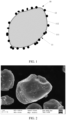
- In some embodiments of this application, viewed along a first direction, an area percent of the first material is 10% to 80% based on an area of the positive active material. The first direction is a direction of observing by using an instrument (such as a scanning electron microscope). Controlling the area percent of the first material within the foregoing range improves the structural stability of the surface of the positive active material and the lithium-ion conductivity, and thereby, improves the cycle performance of the electrochemical device under high temperatures and high voltages. Further, viewed along a first direction, the area percent of the first material is 20% to 75% based on the area of the positive active material.
- In some embodiments of this application, an average particle diameter of the first material is 50 nm to 800 nm. Controlling the average particle diameter of the first material within the foregoing range helps to improve the specific surface area of the first material, and in turn, helps to improve the kinetic performance of the electrochemical device.
- In some embodiments of this application, a thickness of the shell layer is 5 nm to 80 nm. Controlling the thickness of the shell layer within the foregoing range improves the structural stability of a region uncovered with the first material on the surface of the matrix, and in turn, helps to improve the cycle performance of the electrochemical device.
- In some embodiments of this application, a specific surface area of the positive active material is less than or equal to 0.65 m2/g. Controlling the specific surface area of the positive active material within the foregoing range helps to reduce side reactions on the surface of positive active materials, and in turn, helps to improve the cycle performance of the electrochemical device.
- In some embodiments of this application, an average particle size of the matrix is 2 µm to 11 µm.
- In some embodiments of this application, the matrix includes secondary particles. Each secondary particle is formed of primary particles. An average particle size of the primary particles is 1.5 µm to 4.0 µm. Controlling the average particle size of the primary particles within the foregoing range helps to improve the kinetic performance of the electrochemical device.
- A second aspect of this application provides an electrochemical device containing the positive active material described in any embodiment of this application. The positive active material according to this application exhibits high structural stability and possesses a relatively low interfacial charge transfer resistance, so that the electrochemical device according to this application is excellent in cycle performance and kinetic performance.
- A third aspect of this application provides an electronic device. The electronic device includes the electrochemical device according to any embodiment of this application. The electrochemical device according to this application is excellent in cycle performance and kinetic performance, so that the electronic device according to this application is excellent in longevity and performance.
- This application provides a positive active material. The positive active material includes a matrix and a first material existing on a surface of the matrix. The matrix includes a core and a shell layer. An interplanar spacing d1 of a (003) plane of the first material is less than an interplanar spacing d2 of a (003) plane of the core. By controlling the interplanar spacing d1 of the (003) plane of the first material to be less than the interplanar spacing d2 of the (003) plane of the core, the structural stability of the surface of the positive active material can be improved, and an interfacial charge transfer resistance of the positive active material can be reduced, thereby helping to improve both cycle performance and kinetic performance of the electrochemical device.
- To describe the technical solutions in the embodiments of this application more clearly, the following outlines the drawings to be used in the embodiments. Evidently, the drawings outlined below show merely a part of embodiments of this application.
-
FIG. 1 is a schematic structural diagram of a positive active material according to some embodiments of this application; -
FIG. 2 is a scanning electron microscope image of a positive active material according to Embodiment 2-1 of this application; and -
FIG. 3 is a transmission electron microscope and energy dispersive spectrometer (EDS) image of a cross-section of a positive active material according to Embodiment 2-1 of this application. - To make the objectives, technical solutions, and advantages of this application clearer, the following describes this application in more detail with reference to drawings and embodiments. Evidently, the described embodiments are merely a part of but not all of the embodiments of this application. All other embodiments derived by a person of ordinary skill in the art based on the embodiments of this application fall within the protection scope of this application.
- It is hereby noted that in specific embodiments of this application, this application is construed by using a lithium-ion battery as an example of the electrochemical device, but the electrochemical device according to this application is not limited to the lithium-ion battery.
- A first aspect of this application provides a positive active material. As shown in
FIG. 1 , the positiveactive material 10 includes amatrix 11 and afirst material 12 existing on a surface of thematrix 11. Thematrix 11 includes acore 111 and ashell layer 112. An interplanar spacing d1 of a (003) plane of the first material is less than an interplanar spacing d2 of a (003) plane of the core. Without being limited to any theory, the inventor hereof finds that, by controlling the interplanar spacing d1 of the (003) plane of the first material to be less than the interplanar spacing d2 of the (003) plane of the core, it helps to reduce a risk of phase transition failure of an active crystal plane that provides a lithium ion channel at an interface between the active crystal plane and an electrolytic solution, thereby improving structural stability of the surface of the positive active material. In addition, the first material with a relatively small interplanar spacing d1 poses a relatively low resistance to the lithium ions transported in the first material, reducing interfacial charge transfer resistance of the positive active material, thereby helping to improve both cycle performance and kinetic performance of the electrochemical device, for example, reducing the impedance of the electrochemical device, and improving the cycling capacity retention rate of the electrochemical device under high temperatures and high voltages. In addition, on the basis that the cycle performance and the kinetic performance of the electrochemical device are improved, the electrochemical device can provide a higher reversible charge-and-discharge capacity under high voltages, thereby helping to increase the energy density of the electrochemical device. - In some embodiments of this application, d1 < 4.7340 Å, and 4.7340 Å ≤ d2 ≤ 4.7650 Å, and preferably 4.6910 Å ≤ d1 < 4.7340 Å, and 4.7500 Å ≤ d2 ≤ 4.7650 Å. For example, the value of d1 may be 4.6910 Å, 4.6950 Å, 4.7000 Å, 4.7100 Å, 4.7200 Å, 4.7300 Å, 4.7339 Å, or a range formed by any two thereof; and the value of d2 may be 4.7340 Å, 4.7400 Å, 4.7500 Å, 4.7600 Å, 4.7650 Å, or a range formed by any two thereof. By controlling the values of d1 and d2 within the foregoing ranges, the structural stability of the surface of the positive active material and the lithium-ion conductivity can be improved, thereby improving the cycle performance of the electrochemical device under high temperatures and high voltages.
- In some embodiments of this application, based on a number of moles of metal elements other than Li in the shell layer, a molar percent of an element Al in the shell layer is X1; based on a number of moles of metal elements other than Li in the core, a molar percent of an element Al in the core is X2, satisfying: X1 > X2. A relatively large amount of element Al introduced in the shell layer of the positive active material can reduce activity of two-coordinate oxygen on the surface of the shell layer of the positive active material in a high delithiation state, thereby suppressing irreversible phase transition and oxygen release on the surface of the shell layer during a high-voltage charge-and-discharge process of the electrochemical device, improving the structural stability of the surface of the positive active material in the high delithiation state, and in turn, improving the cycle performance of the electrochemical device under high voltages. In addition, with the element Al concentrated richly in the shell layer of the matrix, the stability of the shell layer is relatively higher, and helps to enhance the interfacial stability between the matrix and the first material, reduce the risks of obstructed transport of lithium ions between the matrix and the first material caused by interface failure, and in turn, improve the cycle performance of the electrochemical device under high temperatures and high voltages. In this application, the values of X1 and X2 are not particularly limited, as long as the objectives of this application can be achieved. For example, X1 is 1.5% to 3%, and X2 is 0% to 1.5%. In this application, the molar percents X1 and X2 of the element Al in the shell layer or the core can be obtained by analyzing and testing the cross-section of the positive active material particles using an energy dispersive spectrometer (EDS) in a transmission electron microscope.
- In some embodiments of this application, the first material includes an element Co. Based on a number of moles of metal elements other than Li in the first material, a molar percent of the element Co in the first material is C1. Based on a number of moles of metal elements other than Li in the matrix, a molar percent of the element Co in the matrix is C2, satisfying: C1 > C2. The element Co richly concentrated in the first material of the positive active material helps to further reduce the interfacial charge transfer resistance of the positive active material, and in turn, improve the kinetic performance of the electrochemical device. The content of the element Co in the matrix is not particularly limited in this application, as long as the objectives of this application can be achieved. For example, based on the number of moles of metal elements other than Li in the first material, the molar percent C1 of the element Co in the first material is greater than or equal to 25%.
- In some embodiments of this application, a total number of moles of metal elements other than Li in the core is nM1, a number of moles of an element Ni in the core is nNi1, a number of moles of an element Co in the core is nCo1, a number of moles of an element Mn in the core is nMn1, a number of moles of an element Al in the core is nA1, a number of moles of an element R in the core is nR1, 0.5 ≤ nNi1/nM1 < 1, 0 ≤ nCo1/nM1 ≤ 0.2, 0 ≤ nMn1/nM1 ≤ 0.5, 0 < nAl/nM1 ≤ 0.03, 0 ≤ nR1/nM1 ≤ 0.05, and the element R includes at least one of Mg, Ti, Zr, Nb, Y, Cr, V, Ge, Mo, Fe, Cu, Zn, Ga, Ag, W, In, Sn, Pb, Sb, La, Ce, Ca, or Sr.
- In some embodiments of this application, a total number of moles of metal elements other than Li in the first material is nM2, a number of moles of an element Ni in the first material is nNi2, a number of moles of an element Co in the first material is nCo2, a number of moles of an element Z in the first material is nZ, a number of moles of an element R in the first material is nR2, 0 ≤ nNi2/nM2 ≤ 0.6, 0.25 ≤ nCo2/nM2 ≤ 1.0, 0 ≤ nZ/nM2 ≤ 0.1, 0 ≤ nR2/nM2 ≤ 0.05, the element Z includes at least one of Mn or Al, and the element R includes at least one of Mg, Ti, Zr, Nb, Y, Cr, V, Ge, Mo, Fe, Cu, Zn, Ga, Ag, W, In, Sn, Pb, Sb, La, Ce, Ca, or Sr.
- The use of the foregoing core and/or first material helps to improve both the cycle performance and kinetic performance of the electrochemical device.
- In some embodiments of this application, the core includes Al and R to enhance the stability of the core, and to suppress side reactions between the positive active material and the electrolytic solution when the positive active material is cracked, thereby helping to improve the cycle performance of the electrochemical device.
- Illustratively, the core includes at least one of LiNi0.5Co0.1Mn0.385Al0.012Zr0.002Ti0.001O2, LiNi0.6Co0.1Mn0.288Al0.012O2, LiNi0.8Co0.1Mn0.085Al0.012Zr0.003O2, or LiNi0.6Co0.1Mn0.285Al0.012Zr0.002Ti0.001O2.
- Illustratively, the first material includes at least one of LiNi0.5Co0.45Mn0.05O2, LiNi0.6Co0.35Mn0.05O2, LiCoO2, LiNi0.5Co0.45Mn0.04Al0.01O2, or LiNi0.5Co0.45Mn0.038Al0.01Ti0.001O2.
- In some embodiments of this application, nCo2/nM2 - nCo1/nM1 ≥ 0.25, and preferably 0.25 ≤ nCo2/nM2 - nCo1/nM1 ≤ 0.9. For example, the value of nCo2/nM2 - nCo1/nM1 may be 0.25, 0.3, 0.4, 0.5, 0.6, 0.7, 0.8, 0.9, 1, or a range formed by any two thereof. Controlling the value of nCo2/nM2 - nCo1/nM1 within the foregoing range helps to reduce the interfacial charge transfer resistance of the positive active material, and in turn, improve the kinetic performance of the electrochemical device.
- In some embodiments of this application, viewed along a first direction, an area percent of the first material is 10% to 80% based on an area of the positive active material. Controlling the area percent of the first material within the foregoing range improves the structural stability of the surface of the positive active material and the lithium-ion conductivity, and in turn, improves the cycle performance of the electrochemical device under high temperatures and high voltages.
- In some embodiments of this application, an average particle size of the first material is 50 nm to 800 nm. For example, the average particle size of the first material may be 50 nm, 100 nm, 200 nm, 300 nm, 400 nm, 500 nm, 600 nm, 700 nm, 800 nm, or a range formed by any two thereof. Controlling the particle size of the first material within the foregoing range helps to improve the specific surface area of the first material, and in turn, helps to improve the kinetic performance of the electrochemical device.
- In some embodiments of this application, a thickness of the shell layer is 5 nm to 80 nm. For example, the thickness of the shell layer may be 5 nm, 10 nm, 20 nm, 30 nm, 40 nm, 50 nm, 60 nm, 70 nm, 80 nm, or a range formed by any two thereof. Controlling the thickness of the shell layer within the foregoing range improves the structural stability of a region uncovered with the first material on the surface of the matrix, and in turn, helps to improve the cycle performance of the electrochemical device.
- In some embodiments of this application, an average particle size of the matrix is 2 µm to 11 µm. For example, the average particle size of the matrix may be 2 µm, 3 µm, 4 µm, 5 µm, 6 µm, 7 µm, 8 µm, 9 µm, 10 µm, 11 µm, or a range formed by any two thereof.
- In some embodiments of this application, a specific surface area (BET) of the positive active material is less than or equal to 0.65 m2/g, and further, is 0.4 m2/g to 0.65 m2/g. For example, the specific surface area of the positive active material may be 0.5 m2/g, 0.55 m2/g, 0.6 m2/g, 0.65 m2/g, or a range formed by any two thereof. Controlling the specific surface area of the positive active material within the foregoing range helps to reduce side reactions on the surface of positive active materials, and in turn, helps to improve the cycle performance of the electrochemical device.
- In some embodiments of this application, the matrix includes secondary particles. Each secondary particle is formed of primary particles. An average particle size of the primary particles is 1.5 µm to 4.0 µm. For example, the average particle size of the primary particles may be 1.5 µm, 2.0 µm, 2.5 µm, 3.0 µm, 3.5 µm, 4.0 µm, or a range formed by any two thereof. Controlling the average particle size of the primary particles within the foregoing range helps to improve the kinetic performance of the electrochemical device. In this application, a primary particle means a single particle observed in an SEM image, and a secondary particle means a structure formed of a plurality of aggregated or agglomerated primary particles, and an obvious grain boundary exists between adjacent primary particles.
- The method for preparing the positive active material is not particularly limited in this application, as long as the objectives of this application can be achieved. For example, the method for preparing the positive active material may include, but without being limited to the following steps: optionally adding the foregoing R-source solution into a mixed solution of a Ni source, a Co source, and an Mn source, and preparing a precursor by a co-precipitation method; and then mixing the precursor with a lithium source, optionally adding an Al source and/or the foregoing R-source compound, and performing first sintering in an oxygen or air atmosphere, cooling, pulverizing, and sifting to obtain an intermediate product. The temperature and duration of the first sintering are not particularly limited in this application, as long as the objectives of this application can be achieved. For example, the sintering temperature is 780 °C to 1000 °C, and the sintering duration is 5 hours to 20 hours. The first material may be prepared by a preparation method known in the art. Then, mixing the intermediate product with the first material, optionally adding an Al source and/or the foregoing R-source compound, and performing second sintering in an oxygen or air atmosphere to obtain the positive active material. The temperature and duration of the second sintering are not particularly limited in this application, as long as the objectives of this application can be achieved. For example, the sintering temperature is 500 °C to 750 °C, and the sintering duration is 3 hours to 10 hours. The Al source is added in at least one of the first sintering step or the second sintering step.
- During the preparation of the matrix, the temperature and/or duration of the first sintering usually affects the size of the primary particles. For example, with the increase of the temperature and/or duration of the first sintering, the size of the primary particles in the resulting matrix shows a tendency to increase. With the decrease of the temperature and/or duration of the first sintering, the size of the primary particles in the resulting matrix shows a tendency to decrease.
- A second aspect of this application provides an electrochemical device containing the positive active material described in any embodiment of this application. The positive active material according to this application exhibits high structural stability and possesses a relatively low interfacial charge transfer resistance, so that the electrochemical device according to this application is excellent in cycle performance and kinetic performance.
- The electrochemical device according to this application may include a positive electrode plate. The positive electrode plate is not particularly limited in this application, as long as the objectives of this application can be achieved. For example, the positive electrode plate generally includes a positive current collector. The positive current collector is not particularly limited in this application, as long as the objectives of this application can be achieved. For example, the positive current collector may include, but without being limited to, an aluminum foil, an aluminum alloy foil, a composite current collector, or the like. In this application, the thickness of the positive current collector is not particularly limited, as long as the objectives of this application can be achieved. For example, the thickness is 8 µm to 12 µm. In this application, the positive material layer may be disposed on one surface of the positive current collector in a thickness direction or on both surfaces of the positive current collector in the thickness direction. It is hereby noted that the "surface" here may be the entire region of the positive current collector, or a partial region of the positive current collector, without being particularly limited in this application, as long as the objectives of the application can be achieved.
- In this application, the positive material layer includes the positive active material according to any embodiment of this application described above. The positive material layer may further include a positive binder. The positive binder is not particularly limited in this application, as long as the objectives of this application can be achieved. For example, the binder may include, but without being limited to, at least one of fluorine-containing resin, polypropylene resin, fiber-type binder, rubber-type binder, or polyimide-type binder.
- In this application, the positive material layer may further include a conductive agent. The conductive agent is not particularly limited in this application, as long as the objectives of this application can be achieved. For example, the conductive agent may include, but without being limited to, at least one of conductive carbon black, carbon nanotubes (CNTs), carbon fibers, acetylene black, graphite, Ketjen black, graphene, a metal material, or a conductive polymer. The carbon nanotubes may include, but without being limited to, single-walled carbon nanotubes and/or multi-walled carbon nanotubes. The carbon fibers may include, but without being limited to, vapor grown carbon fibers (VGCF) and/or carbon nanofibers. The metal material may include, but without being limited to, metal powder and/or metal fibers. Specifically, the metal may include, but without being limited to at least one of copper, nickel, aluminum, or silver. The conductive polymer may include, but without being limited to, at least one of polyphenylene derivatives, polyaniline, polythiophene, polyacetylene, or polypyrrole.
- The content of the positive active material, the positive binder, and the conductive agent is not particularly limited in this application, and a conventional content in the art may be employed, as long as the objectives of this application can be achieved. For example, based on the mass of the positive material layer, the mass percent of the positive active material is 90% to 98%, the mass percent of the positive binder is 0.5% to 5%, and the mass percent of the conductive agent is 0.5% to 5%.
- Optionally, the positive electrode plate may further include a conductive layer. The conductive layer is located between the positive current collector and the positive material layer. The components of the conductive layer are not particularly limited in this application, and may be a conductive layer commonly used in the art. For example, the conductive layer may include, but without being limited to, the foregoing conductive agent and positive binder.
- The electrochemical device according to this application may further include a negative electrode plate. The negative electrode plate is not particularly limited in this application, as long as the objectives of this application can be achieved. For example, the negative electrode plate generally includes a negative current collector and a negative material layer. In this application, the negative material layer may be disposed on one surface of the negative current collector in a thickness direction or on both surfaces of the negative current collector in the thickness direction. It is hereby noted that the "surface" here may be the entire region of the negative current collector, or a partial region of the negative current collector, without being particularly limited in this application, as long as the objectives of the application can be achieved.
- The negative current collector is not particularly limited in this application, as long as the objectives of this application can be achieved. For example, the negative current collector may include, but without being limited to, a copper foil, a copper alloy foil, a nickel foil, a stainless steel foil, a titanium foil, foamed nickel, foamed copper, or a composite current collector, or the like. The thickness of the negative current collector is not particularly limited in this application, as long as the objectives of this application can be achieved. For example, the thickness is 4 µm to 12 µm.
- In this application, the negative material layer includes a negative active material. The negative active material is not particularly limited, as long as the objectives of this application can be achieved. For example, the negative active material includes a carbon material that supports reversible intercalation and deintercalation of lithium ions. The carbon material may be a carbon material known in the art to for use as a negative active material. For example, the carbon material may include, but without being limited to, crystalline carbon and/or amorphous carbon. The crystalline carbon may include, but without being limited to, amorphous, flake-shaped, mini-flake-shaped, spherical, or fibrous natural graphite or artificial graphite. The non-crystalline carbon may include, but without being limited to, at least one of soft carbon, hard carbon, mesophase pitch carbide, or calcined coke. Illustratively, the negative active material may include, but without being limited to, natural graphite, artificial graphite, mesocarbon microbead (MCMB), hard carbon, soft carbon, silicon, silicon oxide (SiOx, x is 1 or 2), or a silicon-carbon composite. In the silicon-carbon composite, a mass ratio between silicon and carbon is 1: 10 to 10: 1, and Dv50 is 0.1 µm to 100 µm.
- In this application, the negative material layer may further include a conductive agent. The conductive agent is not particularly limited in this application, as long as the objectives of this application can be achieved. For example, the conductive agent may include, but without being limited to the foregoing conductive agents.
- In this application, the negative material layer may further include a negative binder. The negative binder is not particularly limited in this application, as long as the objectives of this application can be achieved. For example, the negative binder may include, but without being limited to, at least one of polyvinyl alcohol, carboxymethyl cellulose, hydroxypropyl cellulose, diacetyl cellulose, polyvinyl chloride, carboxylated polyvinyl chloride, polyvinyl fluoride, a polymer containing ethylene oxide, polyvinylpyrrolidone, polyurethane, polytetrafluoroethylene, poly(1,1-difluoroethylene), polyethylene, polypropylene, polyacrylic acid, styrene-butadiene rubber, acrylic styrene-butadiene rubber, epoxy resin, or nylon.
- Optionally, the negative electrode plate may further include a conductive layer. The conductive layer is located between the negative current collector and the negative material layer. The components of the conductive layer are not particularly limited in this application, and may be a conductive layer commonly used in the art. The conductive layer may include, but without being limited to, the foregoing conductive agent and the foregoing negative binder.
- In this application, the electrochemical device may further include a separator. The separator is not particularly limited in this application, as long as the objectives of this application can be achieved. For example, the separator may include, but without being limited to, at least one of polyethylene (PE)-based, polypropylene (PP)-based, or polytetrafluoroethylene-based polyolefin (PO) separator, a polyester film (such as polyethylene terephthalate (PET) film), a cellulose film, a polyimide film (PI), a polyamide film (PA), a spandex or aramid film, a woven film, a non-woven film (non-woven fabric), a microporous film, a composite film, separator paper, a laminated film, or a spinning film, and preferably polyethylene or polypropylene. The polyethylene or polypropylene is highly effective in preventing a short-circuit, and can improve the stability of the electrochemical device by virtue of a turn-off effect. The separator according to this application may be a porous structure. The pore size of the separator is not particularly limited, as long as the objectives of this application can be achieved. For example, the pore size may be 0.01 µm to 1 µm. The thickness of the separator is not particularly limited in this application, as long as the objectives of this application can be achieved. For example, the thickness may be 5 µm to 500 µm.
- For example, the separator may include a substrate layer and a surface treatment layer. The substrate layer may be a non-woven fabric, film or composite film, which, in each case, is porous. The material of the substrate layer may include, but without being limited to, at least one of polyethylene, polypropylene, polyethylene terephthalate, or polyimide. Optionally, the substrate layer may be a polypropylene porous film, a polyethylene porous film, a polypropylene non-woven fabric, a polyethylene non-woven fabric, or a polypropylene-polyethylene-polypropylene porous composite film. Optionally, the surface treatment layer is disposed on at least one surface of the substrate layer. The surface treatment layer may be a polymer layer or an inorganic compound layer, or a layer formed by mixing a polymer and an inorganic compound.
- The inorganic compound layer may include, but without being limited to, inorganic particles and an inorganic compound layer binder. The inorganic particles are not particularly limited in this application, and may include, but without being limited to, at least one of aluminum oxide, silicon oxide, magnesium oxide, titanium oxide, hafnium dioxide, tin oxide, ceria, nickel oxide, zinc oxide, calcium oxide, zirconium oxide, yttrium oxide, silicon carbide, boehmite, aluminum hydroxide, magnesium hydroxide, calcium hydroxide, or barium sulfate. The inorganic compound layer binder is not particularly limited in this application, and may include, but without being limited to, at least one of polyvinylidene difluoride, poly(vinylidene difluoride-co-hexafluoropropylene), polyamide, polyacrylonitrile, polyacrylate, polyacrylic acid, polyacrylic acid sodium salt, polyvinylpyrrolidone, polyvinyl ether, poly methyl methacrylate, polytetrafluoroethylene, or polyhexafluoropropylene. The polymer layer includes a polymer, and the material of the polymer may include, but without being limited to, at least one of polyamide, polyacrylonitrile, acrylate polymer, polyacrylic acid, polyacrylate, polyvinylpyrrolidone, polyvinyl ether, polyvinylidene difluoride, or poly(vinylidene difluoride-hexafluoropropylene).
- The electrochemical device according to this application may further include an electrolyte. The electrolyte may include, but without being limited to, one or more of a gel electrolyte, a solid-state electrolyte, or an electrolytic solution. The electrolytic solution may include a lithium salt and a nonaqueous solvent.
- The lithium salt is not particularly limited in this application, as long as the objectives of this application can be achieved. For example, the lithium salt may include, but without being limited to, at least one of LiPF6, LiBF4, LiAsF6, LiClO4, LiB(C6H5)4, LiCH3SO3, LiCF3SO3, LiN(SO2CF3)2, LiC(SO2CF3)3, LiSiF6, LiBOB, or lithium difluoroborate. Preferably, the lithium salt includes LiPF6.
- The nonaqueous solvent is not particularly limited in this application, as long as the objectives of this application can be achieved. For example, the nonaqueous solvent may include, but without being limited to, at least one of a carbonate compound, a carboxylate compound, an ether compound, or other organic solvents. The carbonate compound may include, but without being limited to, at least one of a chain carbonate compound, a cyclic carbonate compound, or a fluorocarbonate compound. The chain carbonate compound may include, but without being limited to, at least one of dimethyl carbonate (DMC), diethyl carbonate (DEC), dipropyl carbonate (DPC), methyl propyl carbonate (MPC), ethylene propyl carbonate (EPC), or ethyl methyl carbonate (EMC). The cyclic carbonate compound may include, but without being limited to, at least one of ethylene carbonate (EC), propylene carbonate (PC), butylene carbonate (BC), or vinyl ethylene carbonate (VEC). The fluorocarbonate compound may include, but without being limited to, at least one of fluoroethylene carbonate (FEC), 1,2-difluoroethylene carbonate, 1,1-difluoroethylene carbonate, 1,1,2-trifluoroethylene carbonate, 1,1,2,2-tetrafluoroethylene carbonate, 1-fluoro-2-methyl ethylene, 1-fluoro-1-methyl ethylene carbonate, 1,2-difluoro-1-methyl ethylene carbonate, 1,1,2-trifluoro-2-methyl ethylene carbonate, or trifluoromethyl ethylene carbonate. The carboxylate compound may include, but without being limited to, at least one of methyl formate, methyl acetate, ethyl acetate, n-propyl acetate, tert-butyl acetate, methyl propionate, ethyl propionate, propyl propionate, γ-butyrolactone, decanolactone, valerolactone, mevalonolactone, or caprolactone. The ether compound may include, but without being limited to, at least one of dibutyl ether, tetraglyme, diglyme, 1,2-dimethoxyethane, 1,2-diethoxyethane, ethoxymethoxyethane, 2-methyltetrahydrofuran, or tetrahydrofuran. The other organic solvent may include, but without being limited to, at least one of dimethyl sulfoxide, 1,2-dioxolane, sulfolane, methyl sulfolane, 1,3-dimethyl-2-imidazolidinone, N-methyl-2-pyrrolidone, formamide, dimethylformamide, acetonitrile, trimethyl phosphate, triethyl phosphate, trioctyl phosphate, or phosphate ester.
- The electrochemical device in this application is not particularly limited, and may be any device in which an electrochemical reaction occurs. In some embodiments, the electrochemical device may include, but without being limited to, a primary battery, a secondary battery, a fuel battery, a solar battery, a capacitor, or the like. Preferably, the electrochemical device may be a lithium secondary battery. The secondary battery may include, but without being limited to, a lithium metal secondary battery, a lithium-ion secondary battery, a lithium polymer secondary battery, a lithium-ion polymer secondary battery, or the like. More preferably, the electrochemical device is a lithium-ion battery.
- The process of preparing the electrochemical device is well known to a person skilled in the art, and is not particularly limited in this application. For example, the preparation process may include, but without being limited to, the following steps: stacking the positive electrode plate, the separator, and the negative electrode plate in sequence, and performing operations such as winding and folding as required to obtain a jelly-roll electrode assembly; putting the electrode assembly into a package, injecting the electrolytic solution into the package, and sealing the package to obtain an electrochemical device; or, stacking the positive electrode plate, the separator, and the negative electrode plate in sequence, and then fixing the four corners of the entire stacked structure by use of adhesive tape to obtain a stacked-type electrode assembly, putting the electrode assembly into a package, injecting the electrolytic solution into the package, and sealing the package to obtain an electrochemical device. In addition, an overcurrent prevention element, a guide plate, and the like may be placed into the package as required, so as to prevent the rise of internal pressure, overcharge, and overdischarge of the electrochemical device.
- A third aspect of this application provides an electronic device. The electronic device includes the electrochemical device according to any embodiment of this application. The electrochemical device according to this application is excellent in cycle performance and kinetic performance, so that the electronic device according to this application is excellent in longevity and operation performance.
- The electronic device according to this application is not particularly limited, and may be any electronic device known in the prior art. In some embodiments, the electronic device may include, but is not limited to, a notebook computer, a pen-inputting computer, a mobile computer, an e-book player, a portable phone, a portable fax machine, a portable photocopier, a portable printer, a stereo headset, a video recorder, a liquid crystal display television set, a handheld cleaner, a portable CD player, a mini CD-ROM, a transceiver, an electronic notepad, a calculator, a memory card, a portable voice recorder, a radio, a backup power supply, a motor, a car, a motorcycle, a power-assisted bicycle, a power tool, an unmanned aerial vehicle, a handheld vacuum cleaner, a bicycle, a lighting appliance, a toy, a game console, a watch, an electric tool, a flashlight, a camera, a large household battery, a lithium-ion capacitor, and the like.
- The implementations of this application are described below in more detail with reference to embodiments and comparative embodiments. Various tests and evaluations are performed in accordance with the following methods. In addition, unless otherwise specified, "proportion" and "%" are based on mass.
- Performing first charging and discharging to a lithium-ion battery in a 45 °C environment. Charging the battery at a constant current of 1.5 C until the voltage reaches 4.35 V, and then charging the battery at a constant voltage until the current reaches 0.05 C. Subsequently, discharging the battery at a constant current of 4 C until the voltage finally reaches 2.8 V, thereby completing one cycle. Recording the discharge capacity as a first-cycle discharge capacity. Repeating the foregoing charge-and-discharge cycle 1000 times, and recording the 1000th-cycle discharge capacity. Cycling capacity retention rate = (1000th - cycle discharge capacity/first-cycle discharge capacity) × 100%.
- Testing 4 lithium-ion batteries prepared in each embodiment or comparative embodiment, and averaging out the values to obtain a final result.
- Testing the lithium-ion battery in a 25 °C environment according to the following steps:
(1) Leaving the battery to stand for 5 minutes; (2) discharging the battery at a constant current of 0.5 C until the voltage reaches 2.8 V; (3) leaving the battery to stand for 5 minutes; (4) charging the battery at a constant current of 1.5 C until the voltage reaches 4.25 V, and then charging the battery at a constant voltage until the current reaches 0.05 C; (5) leaving the battery to stand for 20 minutes; (6) discharging the battery at a constant current of 0.5 C until the voltage reaches 2.8 V (the actual discharge capacity measured is Cactual); (7) leaving the battery to stand for 5 minutes; (8) adjusting the oven temperature to 25 °C; (9) leaving the battery to stand for 60 minutes; (10) charging the battery at a constant current of 1.5 C until the voltage reaches 4.25 V, and then charging the battery at a constant voltage until the current reaches 0.05 C; (11) adjusting the oven temperature to 25 °C; (12) leaving the battery to stand for 60 minutes; (13) discharging the battery at a constant current of 0.1 C for 10 seconds (during which the voltage is sampled at intervals of 0.1 second); (14) discharging the battery at a constant current of 1 C for 360 seconds (during which the voltage is sampled at intervals of 0.1 second); (15) leaving the battery to stand for 120 minutes (during which the voltage is sampled at intervals of 30 seconds); (16) repeating steps (13) to (15) cyclically until the voltage is less than 2.7 V; and (17) leaving the battery to stand for 5 minutes. - The step (14) is to adjust the SOC. The SOC drops by 10% in each discharge step. When the discharge capacity of the battery is close to the Cactual, the battery is discharged for 10 seconds at a current of 0.1 C, the voltage at the end of this discharge step is denoted as Vi, then the battery is discharged at a constant current of 1 C for 360 seconds, during which the voltage at the end of 1 second discharging is denoted as V2.

- Testing the interplanar spacing of the (003) plane and the content of elements:
Fully discharging the lithium-ion battery at a current rate of 0.1 C until the voltage reaches 2.8 V, and leaving the battery to stand for 10 minutes. Subsequently, disassembling the battery in a glovebox to obtain a positive electrode plate. Moving the positive electrode plate into the chamber of a scanning electron microscope (Model: FEI Vion Plasma FIB) equipped with a focused ion beam, in which the positive electrode plate is processed to obtain a specimen suitable for being analyzed in a scanning transmission electron microscope (STEM, model: FEI Titan3 G2 60-300). Protecting the surface of the specimen with Pt, processing the specimen by using a Ga ion beam, and leaving the thickness of the specimen to be not greater than 100 nm. Cleaning the specimen in a low-voltage mode to remove the processing residues on the surface of specimen. Observing the specimen under the STEM. Taking images of lattice fringes in the first material and in the core of the matrix at an appropriate magnification. Measuring, by using image processing software, a distance between n lattice fringes in the first material, denoted as D1, and a distance between n lattice fringes in the core, denoted as D2. Therefore, the interplanar spacing of the (003) plane of the first material is d1 = D1/(n - 1), and the interplanar spacing of the (003) plane of the core is d2 = D2/(n - 1). - In addition, collecting data by use of an X-ray energy dispersive (EDS) analysis function at an appropriate magnification. Performing point-wise scanning at the core, shell layer, and the first material directly by use of the EDS energy spectrum to obtain the content of elements in the first material, core, and shell layer of the positive active material. Collect data from at least 3 different positions, and averaging out the values as a final result.
- As shown in
FIG. 3 , (a) inFIG. 3 is a transmission electron microscope image of a cross-section of the positive active material in Embodiment 2-1; (b) and (c) inFIG. 3 are EDS element analysis images of the cross-section in (a); (b) inFIG. 3 shows the distribution of the element Al; and (c) inFIG. 3 shows the distribution of the element Co. As can be seen from (b) and (c) inFIG. 3 , the Al content and the Co content in theshell layer 112 are greater than the Al content and the Co content in thecore 111 respectively. Signals generated in the region above theshell layer 112 in (b) ofFIG. 3 are interference signals generated by the Pt protection layer on the surface of the specimen. - Observing the specimen under an STEM. Collecting data with an X-ray energy dispersive (EDS) analysis function at an appropriate magnification. Determining an interface between the core and the shell layer according to a difference in the concentration of the element Al. Measuring a distance from the surface of the matrix to this interface by using image processing software. Measuring 10 random points on the surface of the matrix, and averaging out the values as a final result.
- Testing the average particle sizes of the first material and the matrix, and the area percent of the first material:
Observing the positive active material under a scanning electron microscope (SEM). Taking SEM images at an appropriate magnification by using the observation direction as a first direction. Finding the longest diameters of 50 particles of the first material randomly on the surface of the matrix by using image processing software, and averaging out the values as an average particle size of the first material. Finding the longest diameters of 50 matrix particles randomly, and averaging out the values as an average particle size of the matrix. - Selecting 1 positive active material particle randomly by using the image processing software. Determining that the area of the positive active material particle as S, and that the total area of particles of the first material on the surface as S1, so that the area percent of the first material in the particles of the positive active material is S1/S. Measuring 50 particles of the positive active material randomly, and averaging out the values as the area percent of the first material.
-
- (1) Mixing nickel sulfate, cobalt sulfate, and manganese sulfate in deionized water to prepare a mixed salt solution. Adding sodium hydroxide into the deionized water to prepare an alkaline solution. Using ammonia water as a complexant, and adding the salt solution, the alkaline solution, and the complexant into a reaction vessel. Adding aluminum sulfate to react. Controlling the reaction temperature to be 25 °C and the pH to be 11. Filtering the reaction slurry, washing, and drying after the particle size Dv50 reaches a preset value 4.5 µm, so as to obtain a precursor. The nickel sulfate, cobalt sulfate, manganese sulfate, and aluminum sulfate are added at a molar ratio of 0.5: 0.1: 0.385: 0.012 between Ni, Co, Mn, and Al.
- (2) Mixing LiOH·H2O, the precursor, ZrO2, and TiO2 at a molar ratio of 1.05: 0.997: 0.002: 0.001 between Li, Ni+Co+Mn+Al, Zr, and Ti. Adding the mixture into a high-speed mixer to mix well, and then adding the mixture into a saggar, and putting the saggar into a kiln to undergo first sintering under an oxygen atmosphere. Subsequently, mechanically pulverizing, airflow-pulverizing, and grading the sintered product to obtain a matrix precursor. In the first sintering, the sintering temperature is 930 °C and the sintering duration is 12 hours.
- (3) Mixing the matrix precursor and the first material LiNi0.5Co0.45Mn0.05O2 to obtain a mixed material, and then adding the mixed material into a high-speed mixer. Mixing well and then adding the mixture into a saggar. Putting the saggar into a kiln to undergo second sintering in an oxygen atmosphere. Subsequently, mechanically pulverizing the sintered product, and grading, demagnetizing, and sifting the powder to obtain a positive active material. The mass ratio between the first material and the matrix precursor is 2: 100. The average particle size of the first material is 200 nm. In the second sintering, the sintering temperature is 600 °C, and the sintering duration is 6 hours. In the matrix, the core is LiNi0.5Co0.1Mn0.385Al0.012Zr0.002Ti0.001O2.
- Mixing the positive active material prepared above, a conductive agent acetylene black and carbon nanotubes, a binder polyvinylidene difluoride at a mass ratio of 96: 1.2: 0.8: 2, adding N-methyl-pyrrolidone, and stirring the mixture well with a vacuum mixer to obtain a positive slurry, in which a solid content is 70 wt%. Coating one surface of a positive current collector aluminum foil with the positive slurry evenly, and drying the aluminum foil at 120 °C for 1 hour to obtain a positive electrode plate coated with a positive material layer on a single side. Repeating the foregoing steps on the other surface of the aluminum foil to obtain a positive electrode plate coated with the positive material layer on both sides. Subsequently, performing steps of cold calendering, cutting, and slitting to obtain a positive electrode plate.
- Mixing artificial graphite as a negative active material, styrene butadiene rubber as a binder, and sodium carboxymethyl cellulose as a thickener at a mass ratio of 97.4: 1.2: 1.4, adding deionized water, and stirring the mixture well with a vacuum mixer to obtain a negative slurry, in which a solid content is 75 wt%. Coating one surface of a negative current collector copper foil with the negative slurry evenly, and drying the copper foil at 120 °C to obtain a negative electrode plate coated with a negative material layer on a single side. Repeating the foregoing steps on the other surface of the copper foil to obtain a negative electrode plate coated with the negative material layer on both sides. Subsequently, performing steps of cold calendering, cutting, and slitting to obtain a negative electrode plate.
- Mixing propylene carbonate, ethylene carbonate, and diethyl carbonate at a mass ratio of 1: 1: 1 in an dry argon atmosphere glovebox to obtain an organic solvent, adding a lithium salt LiPF6 into the organic solvent to dissolve, and stirring the mixture well to obtain an electrolytic solution. The mass percent of the LiPF6 in the electrolytic solution is 12.5%.
- Using a 7 pm-thick porous polyethylene film as a separator.
- Stacking the prepared positive electrode plate, the separator, and the negative electrode plate sequentially in such a way that the separator is located between the positive electrode plate and the negative electrode plate to serve a function of separation, and winding the stacked structure to obtain an electrode assembly. Putting the electrode assembly into an aluminum plastic film package, drying the packaged electrode assembly, and then injecting the electrolytic solution. Performing vacuum sealing, static standing, chemical formation, degassing, and edge trimming to obtain a lithium-ion battery.
- Identical to Embodiment 1-1 except that the first material in step (3) of <Preparing a positive active material> is replaced with LiNi0.6Co0.35Mn0.05O2.
- Identical to Embodiment 1-1 except that the first material in step (3) of <Preparing a positive active material> is replaced with LiCoO2.
- Identical to Embodiment 1-1 except: the molar ratio between Ni, Co, Mn, and Al in step (1) of <Preparing a positive active material> is 0.6: 0.1: 0.288: 0.012, neither ZrO2 nor TiO2 is added in step (2), the molar ratio between Li and Ni+Co+Mn+Al is 1.05: 1, and the core in the prepared matrix is LiNi0.6Co0.1Mn0.288Al0.012O2.
- Identical to Embodiment 1-1 except: the molar ratio between Ni, Co, Mn, and Al in step (1) of <Preparing a positive active material> is 0.8: 0.1: 0.085: 0.012, no TiO2 is added in step (2), the molar ratio between Li, Ni+Co+Mn+Al, and Zr is 1.05: 0.997: 0.003, the temperature of the first sintering is 830 °C, the first material in step (3) is replaced with LiNi0.6Co0.35Mn0.05O2, and the core in the prepared matrix is LiNi0.8Co0.1Mn0.085Al0.012Zr0.003O2.
- Identical to Embodiment 1-1 except that, in step (3) of <Preparing a positive active material>, the matrix precursor, Al2O3, and the first material LiNi0.5Co0.45Mn0.05O2 are mixed, and, based on the mass of the matrix precursor, the mass percent of Al in the Al2O3 is 0.2%.
- A scanning electron microscope image of the positive active material prepared above is shown in
FIG. 2 , from which it can be seen that the first material is uniformly distributed on the surface of the matrix. - Identical to Embodiment 2-1 except that the first material in step (3) of <Preparing a positive active material> is replaced with LiNi0.6Co0.35Mn0.05O2.
- Identical to Embodiment 2-1 except that the first material in step (3) of <Preparing a positive active material> is replaced with LiCoO2.
- Identical to Embodiment 2-1 except: the molar ratio between Ni, Co, Mn, and Al in step (1) of <Preparing a positive active material> is 0.6: 0.1: 0.288: 0.012, neither ZrO2 nor TiO2 is added in step (2), the molar ratio between Li and Ni+Co+Mn+Al is 1.05: 1, and the core in the prepared matrix is LiNi0.6Co0.1Mn0.288Al0.012O2.
- Identical to Embodiment 2-2 except: the molar ratio between Ni, Co, Mn, and Al in step (1) of <Preparing a positive active material> is 0.6: 0.1: 0.285: 0.012, the temperature of first sintering in step (2) is 910 °C, and the core in the prepared matrix is LiNi0.6Co0.1Mn0.285Al0.012Zr0.002Ti0.001O2.
- Identical to Embodiment 2-5 except that the first material in step (3) of <Preparing a positive active material> is replaced with LiNi0.5Co0.45Mn0.05O2.
- Identical to Embodiment 2-6 except that the first materials in step (3) of <Preparing a positive active material> in the three embodiments are replaced with LiNi0.5Co0.45Mn0.04Al0.01O2, LiNi0.5Co0.45Mn0.039Al0.01Ti0.001O2, and LiCoO2, respectively.
- Identical to Embodiment 2-1 except: the molar ratio between Ni, Co, Mn, and Al in step (1) of <Preparing a positive active material> is 0.8: 0.1: 0.085: 0.012, no TiO2 is added in step (2), the molar ratio between Li, Ni+Co+Mn+Al, and Zr is 1.05: 0.997: 0.003, the temperature of first sintering is 830 °C, and the core in the prepared matrix is LiNi0.8Co0.1Mn0.085Al0.012Zr0.003O2.
- Identical to Embodiment 2-10 except that the first materials in step (3) of <Preparing a positive active material> in the two embodiments are replaced with LiNi0.6Co0.35Mn0.05O2 and LiCoO2 respectively.
- Identical to Embodiment 2-6 except that, in step (3) of <Preparing a positive active material>, Y2O3 is added for sintering, and, based on the mass of the matrix precursor, the mass percent of Y in the Y2O3 is 0.1%.
- Identical to Embodiment 2-6 except that, in step (3) of <Preparing a positive active material>, TiO2 is added for sintering, and, based on the mass of the matrix precursor, the mass percent of Ti in the TiO2 is 0.2%.
- Identical to Embodiment 2-6 except that, in step (3) of <Preparing a positive active material>, TiO2 and WO3 are added for sintering, and, based on the mass of the matrix precursor, the mass percent of Ti in the TiO2 is 0.2%, and the mass percent of W in the WO3 is 0.2%.
- Identical to Embodiment 2-6 except that the temperature of first sintering in step (2) of <Preparing a positive active material> in the two embodiments is adjusted to 880°C and 930°C respectively so that the average particle size of the matrix is consistent with Table 3.
- Identical to Embodiment 2-6 except that the mass percent of Al in step (3) of <Preparing a positive active material> in the three embodiments is adjusted to 0.02%, 0.4%, and 0.8% respectively so that the thickness of the shell layer is consistent with Table 3.
- Identical to Embodiment 2-6 except that the average particle size of the first material in step (3) of <Preparing a positive active material> in the four embodiments is adjusted to 50 nm, 100 nm, 500 nm, and 800 nm respectively.
- Identical to Embodiment 2-6 except that no first material is added in step (3) of <Preparing a positive active materials
- Table 1 to Table 3 show the preparation parameters and performance test results of the embodiments and comparative embodiments.
Table 1 Core First material nCo2/nM2-nCo1/nM1 d2 (Å) d1 (Å) Embodiment 1-1 LiNi0.5Co0.1Mn0.385Al0.012Zr0.002Ti0.001O2 LiNi0.5Co0.45Mn0.05O2 0.35 4.7616 4.7289 Embodiment 1-2 LiNi0.5Co0.1Mn0.385Al0.012Zr0.002Ti0.001O2 LiNi0.6Co0.35Mn0.05O2 0.25 4.7616 4.7319 Embodiment 1-3 LiNi0.5Co0.1Mn0.385Al0.012Zr0.002Ti0.001O2 LiCoO2 0.90 4.7616 4.6912 Embodiment 1-4 LiNi0.6Co0.1Mn0.288Al0.012O2 LiNi0.5Co0.45Mn0.05O2 0.35 4.7496 4.7289 Embodiment 1-5 LiNi0.8Co0.1Mn0.085Al0.012Zr0.003O2 LiNi0.6Co0.35Mn0.05O2 0.25 4.7342 4.7299 Embodiment 2-1 LiNi0.5Co0.1Mn0.385Al0.012Zr0.002Ti0.001O2 LiNi0.5Co0.45Mn0.05O2 0.35 4.7616 4.7289 Embodiment 2-2 LiNi0.5Co0.1Mn0.385Al0.012Zr0.002Ti0.001O2 LiNi0.6Co0.35Mn0.05O2 0.25 4.7616 4.7319 Embodiment 2-3 LiNi0.5Co0.1Mn0.385Al0.012Zr0.002Ti0.001O2 LiCoO2 0.90 4.7616 4.6912 Embodiment 2-4 LiNi0.6Co0.1Mn0.288Al0.012O2 LiNi0.5Co0.45Mn0.05O2 0.35 4.7496 4.7289 Embodiment 2-5 LiNi0.6Co0.1Mn0.285Al0.012Zr0.002Ti0.001O2 LiNi0.6Co0.35Mn0.05O2 0.25 4.7506 4.7319 Embodiment 2-6 LiNi0.6Co0.1Mn0.285Al0.012Zr0.002Ti0.001O2 LiNi0.5Co0.45Mn0.05O2 0.35 4.7506 4.7289 Embodiment 2-7 LiNi0.6Co0.1Mn0.285Al0.012Zr0.002Ti0.001O2 LiNi0.5Co0.45Mn0.04Al0.01O2 0.35 4.7506 4.7219 Embodiment 2-8 LiNi0.6Co0.1Mn0.285Al0.012Zr0.002Ti0.001O2 LiNi0.5Co0.45Mn0.039Al0.01Ti0.001O2 0.35 4.7506 4.7229 Embodiment 2-9 LiNi0.6Co0.1Mn0.285Al0.012Zr0.002Ti0.001O2 LiCoO2 0.90 4.7506 4.6912 Embodiment 2-10 LiNi0.8Co0.1Mn0.085Al0.012Zr0.003O2 LiNi0.5Co0.45Mn0.05O2 0.35 4.7342 4.7289 Embodiment 2-11 LiNi0.8Co0.1Mn0.085Al0.012Zr0.003O2 LiNi0.6Co0.35Mn0.05O2 0.25 4.7342 4.7299 Embodiment 2-12 LiNi0.8Co0.1Mn0.085Al0.012Zr0.003O2 LiCoO2 0.90 4.7342 4.6912 Embodiment 2-13 LiNi0.6Co0.1Mn0.285Al0.012Zr0.002Ti0.001O2 LiNi0.5Co0.45Mn0.05O2 0.35 4.7506 4.7289 Embodiment 2-14 LiNi0.6Co0.1Mn0.285Al0.012Zr0.002Ti0.001O2 LiNi0.5Co0.45Mn0.05O2 0.35 4.7506 4.7289 Embodiment 2-15 LiNi0.6Co0.1Mn0.285Al0.012Zr0.002Ti0.001O2 LiNi0.5Co0.45Mn0.05O2 0.35 4.7506 4.7289 Comparative Embodiment 1-1 LiNi0.6Co0.1Mn0.285Al0.012Zr0.002Ti0.001O2 / / 4.7506 / Note: "/" in Table 1 indicates nonexistence of the corresponding parameter or substance. Table 2 X1 (%) X2 (%) X1/X2 BET of positive active material (m2/g) DCR (mOhm) Cycling capacity retention rate (%) Embodiment 1-1 1.2 1.2 1.00 0.524 2.46 85.4 Embodiment 1-2 1.2 1.2 1.00 0.532 2.37 88.2 Embodiment 1-3 1.2 1.2 1.00 0.542 2.18 90.3 Embodiment 1-4 1.2 1.2 1.00 0.521 2.45 84.1 Embodiment 1-5 1.2 1.2 1.00 0.534 2.78 81.1 Embodiment 2-1 2.0 1.2 1.67 0.523 2.75 92.4 Embodiment 2-2 2.0 1.2 1.67 0.543 2.90 91.0 Embodiment 2-3 2.0 1.2 1.67 0.534 2.40 93.5 Embodiment 2-4 2.0 1.2 1.67 0.551 2.75 86.4 Embodiment 2-5 2.0 1.2 1.67 0.548 2.80 90.5 Embodiment 2-6 2.0 1.2 1.67 0.550 2.65 91.2 Embodiment 2-7 2.0 1.2 1.67 0.537 2.70 92.5 Embodiment 2-8 2.0 1.2 1.67 0.562 2.75 92.9 Embodiment 2-9 2.0 1.2 1.67 0.540 2.30 92.8 Embodiment 2-10 2.0 1.2 1.67 0.546 2.50 87.1 Embodiment 2-11 2.0 1.2 1.67 0.516 2.90 85.1 Embodiment 2-12 2.0 1.2 1.67 0.526 2.20 89.5 Embodiment 2-13 2.0 1.2 1.67 0.523 2.72 92.3 Embodiment 2-14 2.0 1.2 1.67 0.541 2.62 92.7 Embodiment 2-15 2.0 1.2 1.67 0.523 2.5 93.5 Comparative Embodiment 1-1 2.0 1.2 1.67 0.534 3.55 68.5 - As can be seen from Embodiments 1-1 to 1-5 and Comparative Embodiment 1-1, the surface of the matrix in Embodiments 1-1 to 1-5 is coated with the first material, and therefore, the cycling capacity retention rate is higher and the direct current resistance is lower when the lithium-ion battery is charged and discharged at a high rate under high-temperature and high-voltage conditions, indicating that both the cycle performance and kinetic performance of the lithium-ion battery are improved. Possible reasons are: On the one hand, the relatively small interplanar spacing d1 of the (003) plane of the first material reducesa risk of phase transition failure of an active crystal plane that provides a lithium ion channel at an interface between the active crystal plane and an electrolytic solution, thereby improving the structural stability of the surface of the positive active material. On the other hand, due to the relatively small interplanar spacing d1 of the (003) plane, the first material poses a relatively low resistance to the lithium ions transported in the first material, and provides a relatively high lithium-ion conductivity, reducing interfacial charge transfer resistance of the positive active material, and thereby helping to improve both cycle performance and kinetic performance of the lithium-ion battery.
- As can be seen from Embodiments 1-1 to 1-5 and Embodiments 2-1 to 2-15, an Al-rich shell layer that is further disposed in the matrix can further significantly improve the cycle performance of the lithium-ion battery charged and discharged at a high rate under high temperatures and high voltages. Possible reasons are: with the Al-rich shell layer disposed, on the one hand, the Al-rich shell layer helps to improve the structural stability of a region uncovered with the first material on the surface of the matrix. On the other hand, due to relatively high stability of the shell layer, the Al-rich shell layer helps to enhance the interfacial stability between the matrix and the first material, reduce the risks of obstructed transport of lithium ions between the matrix and the first material caused by interface failure, and in turn, further improve the cycle performance of the lithium-ion battery under high temperatures and high voltages.
Table 3 X1 (%) X2 (%) X1/X2 Thickness of shell layer (nm) Average particle size of first material (nm) Average particle size of matrix (µm) Area percent of first material (%) BET of positive active material (m2/g) DCR Cycling capacity retention rate (%) Embodiment 2-6 2.0 1.2 1.67 20 200 2.4 38 0.550 2.65 91.2 Embodiment 3-1 2.0 1.2 1.67 20 200 1.5 25 0.620 2.3 89.30 Embodiment 3-2 2.0 1.2 1.67 20 200 4.0 65 0.430 2.87 93.10 Embodiment 3-3 1.5 1.2 1.25 5 200 2.4 36 0.550 2.43 85.40 Embodiment 3-4 2.5 1.2 2.08 40 200 2.4 35 0.541 2.75 91.70 Embodiment 3-5 3 1.2 2.5 80 200 2.4 32 0.543 2.96 92.50 Embodiment 3-6 2.0 1.2 1.67 20 50 2.4 75 0.551 2.54 88.70 Embodiment 3-7 2.0 1.2 1.67 20 100 2.4 54 0.545 2.6 89.90 Embodiment 3-8 2.0 1.2 1.67 20 500 2.4 21 0.545 2.85 89.30 Embodiment 3-9 2.0 1.2 1.67 20 800 2.4 13 0.537 3.05 84.30 - As can be seen from Embodiment 2-6, Embodiments 3-1 to 3-2, and Embodiments 3-6 to 3-9, by adjusting the relative size of the average particle size between the matrix and the first material, the area percent of the first material in the surface of the positive active material can be adjusted. When the area percent of the first material falls within the range of 20% to 65%, the cycle performance of the lithium-ion battery is higher. As can be seen from Embodiment 2-6 and Embodiments 3-3 to 3-5, a thicker shell layer leads to higher cycle performance of the lithium-ion battery.
- What is described above is merely preferred embodiments of this application, but is not intended to limit this application. Any modifications, equivalent substitutions, and improvements made within the spirit and principles of this application still fall within the protection scope of this application.
Claims (11)
- A positive active material, comprising a matrix and a first material existing on a surface of the matrix, wherein the matrix comprises a core and a shell layer, and an interplanar spacing d1 of a (003) plane of the first material is less than an interplanar spacing d2 of a (003) plane of the core.
- The positive active material according to claim 1, wherein d1 < 4.7340 Å, and 4.7340 Å ≤ d2 ≤ 4.7650 Å.
- The positive active material according to claim 1, wherein, based on a number of moles of metal elements other than Li in the shell layer, a molar percent of an element Al in the shell layer is X1, and, based on a number of moles of metal elements other than Li in the core, a molar percent of an element Al in the core is X2, satisfying: X1 > X2.
- The positive active material according to claim 3, wherein 1.5% ≤ X1 ≤ 3%, and/or X2 ≤ 1.5%.
- The positive active material according to claim 1, wherein the first material comprises an element Co, and, based on a number of moles of metal elements other than Li in the first material, a molar percent of the element Co in the first material is C1, and, based on a number of moles of metal elements other than Li in the matrix, a molar percent of the element Co in the matrix is C2, satisfying: C1 > C2.
- The positive active material according to claim 1, wherein the positive active material satisfies at least one of the following conditions:(a) a total number of moles of metal elements other than Li in the core is nM1, a number of moles of an element Ni in the core is nNi1, a number of moles of an element Co in the core is nCo1, a number of moles of an element Mn in the core is nMn1, a number of moles of an element Al in the core is nAl, a number of moles of an element R in the core is nR1, 0.5 ≤ nNi1/nM1 < 1, 0 ≤ nCo1/nM1 ≤ 0.2, 0 ≤ nMn1/nM1 ≤ 0.5, 0 < nAl/nM1 ≤ 0.03, 0 ≤ nR1/nM1 ≤ 0.05, and the element R comprises at least one of Mg, Ti, Zr, Nb, Y, Cr, V, Ge, Mo, Fe, Cu, Zn, Ga, Ag, W, In, Sn, Pb, Sb, La, Ce, Ca, or Sr; and(b) a total number of moles of metal elements other than Li in the first material is nM2, a number of moles of an element Ni in the first material is nNi2, a number of moles of an element Co in the first material is nCo2, a number of moles of an element Z in the first material is nz, a number of moles of an element R in the first material is nR2, 0 ≤ nNi2/nM2 ≤ 0.6, 0.25 ≤ nCo2/nM2 ≤ 1.0, 0 ≤ nZ/nM2 ≤ 0.1, 0 ≤ nR2/nM2 ≤ 0.05, the element Z comprises at least one of Mn or Al, and the element R comprises at least one of Mg, Ti, Zr, Nb, Y, Cr, V, Ge, Mo, Fe, Cu, Zn, Ga, Ag, W, In, Sn, Pb, Sb, La, Ce, Ca, or Sr.
- The positive active material according to claim 6, wherein nCo2/nM2 - nCo1/nM1 ≥ 0.25.
- The positive active material according to claim 1, wherein the positive active material satisfies at least one of the following conditions:(c) viewed along a first direction, an area percent of the first material is 10% to 80% based on an area of the positive active material;(d) an average particle size of the first material is 50 nm to 800 nm;(e) a thickness of the shell layer is 5 nm to 80 nm; and(f) an average particle size of the matrix is 2 µm to 11 µm.
- The positive active material according to claim 1, wherein a specific surface area of the positive active material is less than or equal to 0.65 m2/g.
- An electrochemical device, comprising the positive active material according to any one of claims 1 to 9.
- An electronic device, comprising the electrochemical device according to claim 10.
Applications Claiming Priority (1)
| Application Number | Priority Date | Filing Date | Title |
|---|---|---|---|
| PCT/CN2021/137773 WO2023108397A1 (en) | 2021-12-14 | 2021-12-14 | Positive electrode active material, electrochemical device, and electronic device |
Publications (2)
| Publication Number | Publication Date |
|---|---|
| EP4394944A1 true EP4394944A1 (en) | 2024-07-03 |
| EP4394944A4 EP4394944A4 (en) | 2025-04-16 |
Family
ID=83758273
Family Applications (1)
| Application Number | Title | Priority Date | Filing Date |
|---|---|---|---|
| EP21967537.8A Pending EP4394944A4 (en) | 2021-12-14 | 2021-12-14 | POSITIVE ELECTRODE ACTIVE MATERIAL, ELECTROCHEMICAL DEVICE AND ELECTRONIC DEVICE |
Country Status (4)
| Country | Link |
|---|---|
| US (1) | US20240322138A1 (en) |
| EP (1) | EP4394944A4 (en) |
| CN (1) | CN115280552A (en) |
| WO (1) | WO2023108397A1 (en) |
Families Citing this family (1)
| Publication number | Priority date | Publication date | Assignee | Title |
|---|---|---|---|---|
| KR20250074445A (en) * | 2023-11-20 | 2025-05-27 | 삼성에스디아이 주식회사 | Positive electrode active material, preparation method thereof, positive electrode, and rechargeable lithium batteries |
Family Cites Families (11)
| Publication number | Priority date | Publication date | Assignee | Title |
|---|---|---|---|---|
| KR100578448B1 (en) * | 2004-11-04 | 2006-05-10 | 한규승 | Method for producing nanoparticle lithium / cobalt oxide, a positive electrode active material for high power lithium secondary batteries using self-mixing eutectic method |
| CN102088084A (en) * | 2009-12-03 | 2011-06-08 | 剩沅科技股份有限公司 | Lithium battery composite electrode active material and preparation method thereof |
| CN103985857A (en) * | 2014-05-19 | 2014-08-13 | 青岛乾运高科新材料股份有限公司 | Mixed lithium battery positive material and preparation method thereof |
| WO2017082083A1 (en) * | 2015-11-10 | 2017-05-18 | Necエナジーデバイス株式会社 | Lithium ion secondary battery and method for manufacturing same |
| CN107611372A (en) * | 2017-08-17 | 2018-01-19 | 格林美(无锡)能源材料有限公司 | A kind of high power capacity high-voltage lithium-battery cathode material and preparation method thereof |
| CN108832089A (en) * | 2018-06-08 | 2018-11-16 | 中南大学 | A kind of molybdenum disulfide coated nickel-cobalt lithium manganate composite material and its preparation method and application |
| CN109860546B (en) * | 2019-01-10 | 2022-02-15 | 宁德新能源科技有限公司 | Cathode material and electrochemical device comprising same |
| CN110247031A (en) * | 2019-05-24 | 2019-09-17 | 乳源东阳光磁性材料有限公司 | Nickelic tertiary cathode material of a kind of cobalt acid lithium cladding and preparation method thereof |
| CN112447966A (en) * | 2019-09-02 | 2021-03-05 | 宁德时代新能源科技股份有限公司 | Positive electrode active material, positive electrode plate and lithium ion secondary battery |
| KR102324691B1 (en) * | 2019-12-19 | 2021-11-09 | 주식회사 포스코 | Cathode active material method for manufacturing the same, and lithium ion battery including the same |
| CN111628149A (en) * | 2020-06-02 | 2020-09-04 | 格林美股份有限公司 | A kind of gradient doped high nickel ternary cathode material and preparation method thereof |
-
2021
- 2021-12-14 WO PCT/CN2021/137773 patent/WO2023108397A1/en not_active Ceased
- 2021-12-14 EP EP21967537.8A patent/EP4394944A4/en active Pending
- 2021-12-14 CN CN202180018075.0A patent/CN115280552A/en active Pending
-
2024
- 2024-03-29 US US18/622,515 patent/US20240322138A1/en active Pending
Also Published As
| Publication number | Publication date |
|---|---|
| US20240322138A1 (en) | 2024-09-26 |
| CN115280552A (en) | 2022-11-01 |
| WO2023108397A1 (en) | 2023-06-22 |
| EP4394944A4 (en) | 2025-04-16 |
Similar Documents
| Publication | Publication Date | Title |
|---|---|---|
| US12500239B2 (en) | Anode material, anode and electrochemical device comprising the anode material | |
| US11121367B2 (en) | Modified positive electrode active material, method for preparing the same and electrochemical energy storage device | |
| EP4693499A1 (en) | Negative electrode active material and preparation method therefor, and secondary battery and electronic device | |
| US20030082453A1 (en) | Secondary battery positive electrode and secondary battery using the same | |
| EP4489109A1 (en) | Electrochemical device, and electronic device comprising same | |
| EP4089762A1 (en) | Positive electrode plate, and electrochemical device and electronic device containing positive electrode plate | |
| WO2022198660A1 (en) | Positive electrode lithium supplementing material, and positive electrode plate and electrochemical device including same | |
| EP4350811A1 (en) | Lithium transition metal composite oxide, electrochemical device and electronic device | |
| US20220045325A1 (en) | Positive electrode material, electrochemical device containing same, and electronic device | |
| US20240282940A1 (en) | Positive active material, positive electrode plate and electrochemical device containing same, and electronic device | |
| EP4439722A1 (en) | Positive electrode active material, electrochemical device comprising positive electrode active material, and electronic device | |
| US12119490B2 (en) | Positive electrode active material and secondary battery | |
| US20240347712A1 (en) | Electrochemical device and electronic device | |
| US20240243282A1 (en) | Electrochemical device and electronic device | |
| EP4428949A1 (en) | Cathode active material for lithium secondary battery and method for manufacturing same | |
| EP4535464A1 (en) | Electrochemical device and electric device | |
| US20240322138A1 (en) | Positive electrode active material, electrochemical device, and electronic device | |
| CN117293287A (en) | Cathode materials and electrochemical devices and electronic devices containing the materials | |
| JP2024524099A (en) | Electrochemical device and electronic device including said electrochemical device | |
| EP4601040A1 (en) | Positive electrode active material, positive electrode sheet, secondary battery, electric device, and preparation method | |
| JP2005142004A (en) | Non-aqueous electrolyte secondary battery | |
| EP4432377A2 (en) | Negative electrode plate, secondary battery, and electronic apparatus | |
| EP4679525A1 (en) | Negative electrode active material, negative electrode sheet, battery, and electric device | |
| EP4674816A1 (en) | Cathode active material for lithium secondary battery and lithium secondary battery including the same | |
| KR20240148286A (en) | Positive electrode active material, and positive electrode and lithium secondary battery comprising the same |
Legal Events
| Date | Code | Title | Description |
|---|---|---|---|
| STAA | Information on the status of an ep patent application or granted ep patent |
Free format text: STATUS: THE INTERNATIONAL PUBLICATION HAS BEEN MADE |
|
| PUAI | Public reference made under article 153(3) epc to a published international application that has entered the european phase |
Free format text: ORIGINAL CODE: 0009012 |
|
| STAA | Information on the status of an ep patent application or granted ep patent |
Free format text: STATUS: REQUEST FOR EXAMINATION WAS MADE |
|
| 17P | Request for examination filed |
Effective date: 20240327 |
|
| AK | Designated contracting states |
Kind code of ref document: A1 Designated state(s): AL AT BE BG CH CY CZ DE DK EE ES FI FR GB GR HR HU IE IS IT LI LT LU LV MC MK MT NL NO PL PT RO RS SE SI SK SM TR |
|
| DAV | Request for validation of the european patent (deleted) | ||
| DAX | Request for extension of the european patent (deleted) | ||
| A4 | Supplementary search report drawn up and despatched |
Effective date: 20250314 |
|
| RIC1 | Information provided on ipc code assigned before grant |
Ipc: C01G 53/506 20250101ALI20250310BHEP Ipc: C01G 53/504 20250101ALI20250310BHEP Ipc: H01M 10/0525 20100101ALI20250310BHEP Ipc: H01M 4/50 20100101ALI20250310BHEP Ipc: H01M 4/505 20100101ALI20250310BHEP Ipc: H01M 4/52 20100101ALI20250310BHEP Ipc: H01M 4/525 20100101AFI20250310BHEP |